EP4002579B1 - Gnss-antenne - Google Patents
Gnss-antenne Download PDFInfo
- Publication number
- EP4002579B1 EP4002579B1 EP21209198.7A EP21209198A EP4002579B1 EP 4002579 B1 EP4002579 B1 EP 4002579B1 EP 21209198 A EP21209198 A EP 21209198A EP 4002579 B1 EP4002579 B1 EP 4002579B1
- Authority
- EP
- European Patent Office
- Prior art keywords
- antenna
- radiating element
- stubs
- mesh structure
- feed lines
- Prior art date
- Legal status (The legal status is an assumption and is not a legal conclusion. Google has not performed a legal analysis and makes no representation as to the accuracy of the status listed.)
- Active
Links
Images




Classifications
-
- H—ELECTRICITY
- H01—ELECTRIC ELEMENTS
- H01Q—ANTENNAS, i.e. RADIO AERIALS
- H01Q1/00—Details of, or arrangements associated with, antennas
- H01Q1/36—Structural form of radiating elements, e.g. cone, spiral, umbrella; Particular materials used therewith
- H01Q1/38—Structural form of radiating elements, e.g. cone, spiral, umbrella; Particular materials used therewith formed by a conductive layer on an insulating support
-
- B—PERFORMING OPERATIONS; TRANSPORTING
- B60—VEHICLES IN GENERAL
- B60J—WINDOWS, WINDSCREENS, NON-FIXED ROOFS, DOORS, OR SIMILAR DEVICES FOR VEHICLES; REMOVABLE EXTERNAL PROTECTIVE COVERINGS SPECIALLY ADAPTED FOR VEHICLES
- B60J1/00—Windows; Windscreens; Accessories therefor
- B60J1/20—Accessories, e.g. wind deflectors, blinds
-
- B—PERFORMING OPERATIONS; TRANSPORTING
- B60—VEHICLES IN GENERAL
- B60J—WINDOWS, WINDSCREENS, NON-FIXED ROOFS, DOORS, OR SIMILAR DEVICES FOR VEHICLES; REMOVABLE EXTERNAL PROTECTIVE COVERINGS SPECIALLY ADAPTED FOR VEHICLES
- B60J7/00—Non-fixed roofs; Roofs with movable panels, e.g. rotary sunroofs
-
- H—ELECTRICITY
- H01—ELECTRIC ELEMENTS
- H01Q—ANTENNAS, i.e. RADIO AERIALS
- H01Q1/00—Details of, or arrangements associated with, antennas
- H01Q1/12—Supports; Mounting means
- H01Q1/1271—Supports; Mounting means for mounting on windscreens
-
- H—ELECTRICITY
- H01—ELECTRIC ELEMENTS
- H01Q—ANTENNAS, i.e. RADIO AERIALS
- H01Q1/00—Details of, or arrangements associated with, antennas
- H01Q1/27—Adaptation for use in or on movable bodies
- H01Q1/32—Adaptation for use in or on road or rail vehicles
- H01Q1/3208—Adaptation for use in or on road or rail vehicles characterised by the application wherein the antenna is used
- H01Q1/3233—Adaptation for use in or on road or rail vehicles characterised by the application wherein the antenna is used particular used as part of a sensor or in a security system, e.g. for automotive radar, navigation systems
-
- H—ELECTRICITY
- H01—ELECTRIC ELEMENTS
- H01Q—ANTENNAS, i.e. RADIO AERIALS
- H01Q1/00—Details of, or arrangements associated with, antennas
- H01Q1/27—Adaptation for use in or on movable bodies
- H01Q1/32—Adaptation for use in or on road or rail vehicles
- H01Q1/325—Adaptation for use in or on road or rail vehicles characterised by the location of the antenna on the vehicle
-
- H—ELECTRICITY
- H01—ELECTRIC ELEMENTS
- H01Q—ANTENNAS, i.e. RADIO AERIALS
- H01Q1/00—Details of, or arrangements associated with, antennas
- H01Q1/36—Structural form of radiating elements, e.g. cone, spiral, umbrella; Particular materials used therewith
-
- H—ELECTRICITY
- H01—ELECTRIC ELEMENTS
- H01Q—ANTENNAS, i.e. RADIO AERIALS
- H01Q1/00—Details of, or arrangements associated with, antennas
- H01Q1/48—Earthing means; Earth screens; Counterpoises
-
- H—ELECTRICITY
- H01—ELECTRIC ELEMENTS
- H01Q—ANTENNAS, i.e. RADIO AERIALS
- H01Q1/00—Details of, or arrangements associated with, antennas
- H01Q1/50—Structural association of antennas with earthing switches, lead-in devices or lightning protectors
-
- H—ELECTRICITY
- H01—ELECTRIC ELEMENTS
- H01Q—ANTENNAS, i.e. RADIO AERIALS
- H01Q5/00—Arrangements for simultaneous operation of antennas on two or more different wavebands, e.g. dual-band or multi-band arrangements
- H01Q5/20—Arrangements for simultaneous operation of antennas on two or more different wavebands, e.g. dual-band or multi-band arrangements characterised by the operating wavebands
- H01Q5/28—Arrangements for establishing polarisation or beam width over two or more different wavebands
-
- H—ELECTRICITY
- H01—ELECTRIC ELEMENTS
- H01Q—ANTENNAS, i.e. RADIO AERIALS
- H01Q5/00—Arrangements for simultaneous operation of antennas on two or more different wavebands, e.g. dual-band or multi-band arrangements
- H01Q5/30—Arrangements for providing operation on different wavebands
- H01Q5/307—Individual or coupled radiating elements, each element being fed in an unspecified way
- H01Q5/342—Individual or coupled radiating elements, each element being fed in an unspecified way for different propagation modes
- H01Q5/35—Individual or coupled radiating elements, each element being fed in an unspecified way for different propagation modes using two or more simultaneously fed points
-
- H—ELECTRICITY
- H01—ELECTRIC ELEMENTS
- H01Q—ANTENNAS, i.e. RADIO AERIALS
- H01Q9/00—Electrically-short antennas having dimensions not more than twice the operating wavelength and consisting of conductive active radiating elements
- H01Q9/04—Resonant antennas
- H01Q9/0407—Substantially flat resonant element parallel to ground plane, e.g. patch antenna
- H01Q9/0428—Substantially flat resonant element parallel to ground plane, e.g. patch antenna radiating a circular polarised wave
-
- H—ELECTRICITY
- H01—ELECTRIC ELEMENTS
- H01Q—ANTENNAS, i.e. RADIO AERIALS
- H01Q9/00—Electrically-short antennas having dimensions not more than twice the operating wavelength and consisting of conductive active radiating elements
- H01Q9/04—Resonant antennas
- H01Q9/0407—Substantially flat resonant element parallel to ground plane, e.g. patch antenna
- H01Q9/0428—Substantially flat resonant element parallel to ground plane, e.g. patch antenna radiating a circular polarised wave
- H01Q9/0435—Substantially flat resonant element parallel to ground plane, e.g. patch antenna radiating a circular polarised wave using two feed points
-
- H—ELECTRICITY
- H01—ELECTRIC ELEMENTS
- H01Q—ANTENNAS, i.e. RADIO AERIALS
- H01Q5/00—Arrangements for simultaneous operation of antennas on two or more different wavebands, e.g. dual-band or multi-band arrangements
- H01Q5/30—Arrangements for providing operation on different wavebands
Definitions
- the present disclosure relates generally to an antenna, and more particularly, to an antenna being mounted on a vehicle.
- GNSS global navigation satellite system
- a position estimation starts with reception of a satellite signal through a GNSS antenna.
- placement of the GNSS antenna is important for the reliability and accuracy of position estimates.
- a GNSS antenna may provide an optimal performance at a topmost part of a vehicle than in any other positions in the vehicle.
- a GNSS antenna is usually placed in a shark-fin antenna assembly with other antennas for other systems or below the top of the front windshield. These placements provide a poor compromise in terms of technical performance.
- an electronic device may include a substrate and a stacked arrangement of layers thereon.
- the stacked arrangement of layers may include a visual display layer, and a patch antenna above the visual display layer.
- the patch antenna may include an optically transmissive electrically conductive mesh.
- WO2020/095786 discloses a substrate provided with: a dielectric layer that transmits visible light and that has a first surface and a second surface on the opposite side from the first surface; a mesh-like antenna conductor provided on the first surface side; and a mesh-like ground conductor provided on the second surface side.
- US2003/142018 provides an inexpensive transparent microwave antenna with high efficiency.
- Conductors for the antennas are formed from metallic meshes with a net transparency greater than 70% and supported by a clear substrate. The associated antenna gain efficiencies are greater than 50%.
- an antenna includes: an optically transparent substrate layer having a first surface and an opposing second surface; a radiating element having a first mesh structure and disposed on the first surface of the substrate layer; a ground plane having a second mesh structure formed on the second surface of the substrate layer; at least two feed lines configured to connect the radiating element to an external circuit; and at least two stubs connected to the radiating element, wherein the at least two feed lines are substantially parallel or perpendicular to each other, and each of the at least two feed lines has a third mesh structure.
- a GNSS receiver receives a satellite signal transmitted from a GNSS satellite constellation through a GNSS antenna and determines the position of the receiver.
- a high-precision GNSS position determination requires operation at two frequency bands for positioning accuracy.
- a GNSS antenna operating at two frequency bands usually has significantly larger size, especially in terms of height or antenna profile, compared to a single frequency band antenna. This prohibits placement of the GNSS antenna in an optimal position (e.g., a topmost part) of a vehicle.
- An optically transparent GNSS antenna placed on a glass roof or a glass window of a vehicle may provide a good solution.
- a material with high optical transparency needs to be used for manufacturing the antenna.
- widely used optically transparent conductors, such as Indium Tin Oxide (ITO) have relatively low conductivity for GNSS antenna implementation, leading to poor efficiency and performance degradation.
- GNSS antenna structure needs to be planar with no via holes for the glass surface (e.g., a glass roof implementation) to have higher overall transparency with lower fabrication complexity.
- Embodiments of the present disclosure provide an antenna, an antenna sticker, and an antenna coated on a glass roof or a glass window of a vehicle.
- the antenna includes an optically transparent substrate layer, a radiating element disposed on a first surface of the substrate layer, a ground plane disposed on a second surface of the substrate layer, at least two feed lines configured to connect the radiating element to an external circuit, and at least two stubs connected to the radiating element.
- the radiating element has a mesh structure that is concentric around a circular patch and rectangular along a feeding direction.
- the ground plane may have a second mesh structure.
- Each of the at least two feed lines may include first and second rectangular portions, the first rectangular portion having a width smaller than a width of the second rectangular portion.
- the at least two stubs may be tilted and connected to recesses formed on the radiating element.
- Embodiments disclosed herein have one or more technical effects.
- Using a transparent substrate ensures overall optical transparency of the antenna.
- a mesh structure having a plurality of openings for the radiating element and the ground plane By utilizing a mesh pattern that is concentric around a circular radiating element and rectangular along a feeding direction, high efficiency of the antenna is achieved.
- two feed lines that are partially thinned and have a mesh structure By utilizing two feed lines that are partially thinned and have a mesh structure, good impedance matching and high efficiency are obtained. Connecting a plurality of stubs to the circumference of the radiating element having recesses allows for achievement of target frequency bands by adjusting an input impedance of the stubs.
- the structure of antennas of the present disclosure allows for easy integration without critical alignment (e.g., a sub-millimeter scale) for feeding, compared with an aperture-coupled feed from a bottom layer.
- the overall optical transparency of the antennas allows for placement of the antennas at an optimum location, e.g., a top-most part of a vehicle, without impeding visual appearance.
- the antennas can be manufactured as additive stickers or coated onto a glass roof or a glass window of a vehicle, providing convenience and reduced cost.
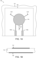
- FIG. 1A is a schematic diagram illustrating a top view of an antenna
- FIG. 1B is a schematic diagram illustrating a side view of the antenna, consistent with some embodiments of the present disclosure.
- an antenna 100 includes a substrate 102, a radiating element 104 disposed on a top surface of substrate 102, and a ground plane 106 formed on a bottom surface of substrate 102.
- substrate 102 maybe made of an optically transparent material, such as a glass or a polymer.
- the selection of materials for substrate 102 is not so limited, and any low dielectric loss material having a suitable dielectric constant and optical transparency can be used as the substrate.
- Radiating element 104 is a conductive layer such as a metal or metal alloy that forms a patch layer.
- radiating element 104 may be a metal layer having a moderate conductivity.
- radiating element 104 is not so limited. Any material having a suitable conductivity can be used as radiating element 104.
- Radiating element 104 may be formed by thin-film deposition or plating or any other method known in the art.
- radiating element 104 has a mesh structure that includes a plurality of openings. The plurality of openings in the mesh structure allows for transmission of ambient light, e.g., sunlight, through the openings, thereby increasing overall optical transparency of the antenna.
- antenna 100 includes ground plane 106.
- Ground plane 106 may be a conductive layer such as a metal or a metal alloy.
- ground plane 106 has a mesh structure.
- the mesh structure of ground plane 106 may be the same as or different from the mesh structure of radiating element 104.
- antenna 100 includes a feed line 108a and a feed line 108b that are connected to radiating element 104.
- Feed lines 108a and 108b are configured to connect radiating element 104 to an external circuit (not shown) to feed two frequency bands simultaneously.
- feed lines 108a and 108b are substantially parallel to each other.
- Each of feed lines 108a and 108b includes a first rectangular portion (the top portions of feed lines 108a and 108b) connected to radiating element 104 and a second rectangular portion (the bottom portions of feed lines 108a and 108b) connected to the external circuit.
- the first rectangular portion may be thinned so that it has a width smaller than a width of the second rectangular portion. Thinning the portions of the feed lines connected to the radiating element allows for facilitation of matching and reduction of cross-coupling of the feed lines.
- Each of feed lines 108a and 108b has a mesh pattern.
- antenna 100 may have more than two feed lines connected to radiating element 104 so that a plurality of frequency bands can be fed to the antenna.
- antenna 100 includes stubs 110a, 110b, and 110c that are connected to radiating element 104.
- radiating element 104 may have a circular shape and stubs 110a, 110b, and 110c can be connected to a circumference of radiating element 104.
- stubs 110a, 110b, and 110c are evenly distributed along the circumference of radiating element 104 such that the angle between stub 110a and stub 110b is 120 degrees and the angle between stub 110b and stub 110c is also 120 degrees.
- Each of stubs 110a, 110b, and 110c may or may not have a mesh pattern.
- each of stubs 110a, 110b, and 110c may instead be formed as a very thin line (e.g., 0.2-0.5 mm). Using the stubs connected to the radiating element allows for achievement of high efficiency, and a good axial ratio and gain at two frequency bands.
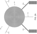
- FIG. 2A is a schematic diagram illustrating an exemplary mesh structure of a top surface 200 of an antenna
- FIG. 2B is a schematic diagram illustrating an exemplary mesh structure of a bottom surface 220 of an antenna, consistent with some embodiments of the present disclosure.
- top surface 200 of the antenna includes a mesh structure for a radiating element 204, and mesh structures for feed lines 208a and 208b.
- each of feed lines 208a and 208b in FIG. 2A is bent at the joint of the thinner leg and the thicker leg.
- Top surface 200 of the antenna also includes stubs 210a, 210b, and 210c.
- the mesh structure for radiating element 204 has a plurality of concentrically arranged openings to form a circular mesh-patterned patch.
- the design of the mesh structure is not so limited. Any mesh pattern providing a plurality of openings and high efficiency of the antenna can be adopted for the mesh structure.
- bottom surface 220 of the antenna includes a mesh structure for a ground plane 206, such as ground plane 106 of FIG. 1A .
- ground plane 206 has a mesh structure different from the mesh structure of radiating element 204.
- Using a transparent substrate ensures optical transparency of the antenna.
- a mesh structure having a plurality of openings for the radiating element and the ground plane, light transmission through the openings is ensured, leading to enhanced overall optical transparency of the antenna.
- high efficiency of the antenna is achieved.
- two partially thinned feed lines and a plurality of stubs connected to the circumference of the radiating element high efficiency, and a good axial ratio and a high gain of dual frequency bands are obtained.
- the two frequency bands applied to antenna 100 are L1 (1575.4 MHz) and L5 (1176.4 MHz), and a frequency ratio L1/L5 of 1.3 is obtained.
- two frequency band antenna properties are simulated using antenna 100 shown in FIGs. 1A-1B .
- Operation of antenna 100 is simulated at the frequency bands L1 and L5.
- the simulation results are shown in FIGs. 3-7 , described below.
- FIG. 3 is a plot illustrating simulated reflection coefficients of antenna 100 as a function of frequency, consistent with some embodiments of the present disclosure.
- a reflection coefficient (or return loss) represents how much power is reflected from the antenna. For example, a zero reflection coefficient indicates that all the power is reflected from the antenna and no power is radiated.
- line 302 and line 304 illustrate reflection coefficients S11 and S22 at two ports (not shown) of antenna 100, respectively, and line 306 illustrates a forward gain S21. As shown in FIG.
- reflection coefficients S11 and S22 show a peak at frequency ranges of 1550-1606 MHz and 1166-1186 MHz, indicating a good match with the L1 frequency band (1575.4 MHz) and L5 frequency band (1176.4 MHz), respectively.
- the forward gain S21 indicates sufficient isolation between the two ports, which ensures a good axial ratio of antenna 100.
- FIG. 4A is a plot illustrating a simulated realized right hand circularly polarized (RHCP) signal radiation pattern (marked m1) , and a simulated realized left hand circularly polarized (LHCP) signal radiation pattern (marked m2), at a first L1 frequency band edge (1560 MHz)
- FIG. 4B is a plot illustrating a simulated realized RHCP signal radiation pattern (marked m1), and a simulated realized LHCP signal radiation pattern (marked m2), at a second L1 frequency band edge (1608 MHz), consistent with some embodiments of the present disclosure.
- RHCP right hand circularly polarized
- LHCP left hand circularly polarized
- FIG. 5A is a plot illustrating a simulated realized RHCP signal radiation pattern (marked m1), and a simulated realized LHCP signal radiation pattern (marked m2), at a first L5 frequency band edge (1160 MHz)
- FIG. 5B is a plot illustrating a simulated realized RHCP signal radiation pattern (marked m1), and a simulated realized LHCP signal radiation pattern (marked m2), at a second L5 frequency band edge (1188 MHz), consistent with some embodiments of the present disclosure.
- FIGs. 5A and 5B again, radiation patterns with dominating RHCP signals and a peak gain towards zenith are obtained.
- FIG. 6 is a plot illustrating a simulated realized RHCP gain towards a zenith of an antenna as a function of frequency, consistent with some embodiments of the present disclosure.
- the gray bar at the left side represents a frequency range of interest for the L5 frequency band and the gray bar at the right side represents a frequency range of interest for the L1 frequency band.
- a maximum gain of 4.5 dB at L5 frequency band, and a maximum gain of 3.5 dB at L1 frequency band are obtained, which is very good given the moderate effective conductivity of the conductors used for the antenna.
- FIG. 7 is a plot illustrating a simulated antenna radiation efficiency as a function of frequency, consistent with some embodiments of the present disclosure.
- the gray bar at the left side represents a frequency range of interest for the L5 frequency band and the gray bar at the right side represents a frequency range of interest for the L1 frequency band.
- the simulated antenna radiation efficiency is on the order of 50% in both frequency bands, which is very good given the moderate conductivity of the conductors used for the antenna.
- FIG. 8 is a schematic diagram illustrating a top view of an antenna 800, consistent with some embodiments of the present disclosure.
- antenna 800 includes a substrate (not shown), a radiating element 804 disposed on a top surface of the substrate, a ground plane 806 formed on a bottom surface of the substrate.
- Radiating element 804 is a conductive layer having a mesh structure, such as radiating element 104 in FIG. 1A .
- radiating element 804 has three recesses disposed on its circumference. The three recesses may be evenly spaced or distributed along the circumference, e.g., at 120 degrees.
- Antenna 800 includes three stubs 810a, 810b, and 810c, each of the stubs connected to a corresponding one of the recesses.
- the three stubs may be evenly spaced or distributed along the circumference, e.g., at 120 degrees.
- each of the three stubs is tilted.
- Antenna 800 includes a feed line 808a and a feed line 808b connected to radiating element 804 to feed two frequency bands simultaneously.
- 808a and 808b are similar to feed lines 108a and 108b, except that feed lines 808a and 808b are substantially perpendicular to each other. Forming recesses on the radiating element and/or tilting the stubs allow for achievement of target frequency bands by promoting impedance matching and adjusting input impedance of the antenna.
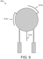
- FIG. 9 is a schematic diagram illustrating a top view of an antenna 900, consistent with some embodiments of the present disclosure.
- Antenna 900 is similar to antenna 100 in FIG. 1A , except that antenna 900 includes stubs that are bent to a certain direction.
- antenna 900 includes three stubs 910a, 910b, and 910c.
- the three stubs may be evenly spaced or distributed along the circumference, e.g., at 120 degrees.
- stubs 910a and 910b are bent such that a portion of each of stubs 910a and 910b (the unbent portion) is perpendicular to the circumference of the radiating element of antenna 900, while a portion of each of stubs 910a and 910b (the bent portion) is parallel to the circumference of the radiating element of antenna 900.
- Stubs 910a and 910b may be bent to the same direction, for example, a counter-clockwise direction, as shown in FIG. 9 .
- stubs 910a and 910b may be bent to a clockwise direction.
- stub 910c is not bent and extends radially from radiating element of the antenna. In an embodiment, only one of the three stubs may be bent.
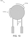
- FIG. 10 is a schematic diagram illustrating a top view of an antenna 1000, consistent with some embodiments of the present disclosure.
- Antenna 1000 is similar to antenna 900 in FIG. 9 , except that in antenna 1000, a bent portion and an unbent portion of a stub meet to form a curved portion.
- antenna 1000 includes three stubs 1010a, 1010b, and 1010c.
- the three stubs may be evenly spaced or distributed along the circumference, e.g., at 120 degrees.
- stubs 1010a and 1010b are bent such that a portion of each of stubs 1010a and 1010b (the bent portion) is parallel to the circumference of the radiating element of antenna 1000.
- the bending is smooth such that the bent portion and the unbent portion meet to form a curved portion.
- Stubs 1010a and 1010b may be bent to the same direction, for example, a counter-clockwise direction, as shown in FIG. 10 .
- stubs 1010a and 1010b may be bent to a clockwise direction.
- stub 1010c is not bent and extends radially from radiating element of the antenna. In an embodiment, only one of the three stubs may be bent.
- FIG. 11 is a schematic diagram illustrating a top view of an antenna 1100, consistent with some embodiments of the present disclosure.
- Antenna 1100 is similar to antenna 900 in FIG. 9 , except that in antenna 1100, two stubs are bent to different directions.
- antenna 1100 includes three stubs 1110a, 1110b, and 1110c.
- the three stubs may be evenly spaced or distributed along the circumference, e.g., at 120 degrees.
- stub 1110a is bent to a clockwise direction while stub 1110b is bent to a counter-clockwise direction, as shown in FIG. 11 .
- stub 1110a may be bent to a counter-clockwise direction while stub 1110b may be bent to a clockwise direction.
- FIG. 12 is a schematic diagram illustrating a top view of an antenna 1200, consistent with some embodiments of the present disclosure.
- Antenna 1200 is similar to antenna 100 in FIG. 1A , except that antenna 1200 only has two stubs (1210a and 1210b), instead of three stubs as shown in FIG. 1A .
- stubs 1210a and 1210b extend radially and are on the opposite side of the radiating element from the feed lines.
- Stubs 1210a and 1210b may be symmetrically positioned relative to the two feed lines and are spaced, e.g., 120 degrees apart.
- FIG. 13 is a schematic diagram illustrating a top view of an antenna 1300, consistent with some embodiments of the present disclosure.
- Antenna 1300 is similar to antenna 100 in FIG. 1A , except that antenna 1300 has four stubs (1310a, 1310b, 1310c, and 1310d), instead of three stubs as shown in FIG. 1A .
- the four stubs are evenly distributed, and are symmetrical with respect to the two feed lines, as shown in FIG. 13 .
- Stubs 1310a and 1310c may be formed on a same line (a vertical line) and stubs 1310b and 1310d may be formed on a same line (a horizontal line).
- the four stubs extend radially, as shown in FIG. 13 .
- the four stubs may be bend, similar to the bent stubs in FIGs. 9 and 10 .
- FIG. 14 is a schematic diagram illustrating a side view of an antenna1400, consistent with some embodiments of the present disclosure.
- antenna 1400 includes a transparent substrate 1402 (e.g., a glass layer), a radiating element 1404 disposed on a top surface of substrate 1402, and a ground plane 1406 formed on a bottom surface of substrate 1402.
- Antenna 1400 includes a second glass layer 1412 disposed on the top of radiating element 1404 such that radiating element 1404 is sandwiched in between substrate 1402 and glass layer 1412 to form a glass laminate structure.
- the empty space between substrate 1402 and glass layer 1412 can be filled with a transparent plastic element 1414 so that the plastic element surrounds radiating element 1404 to provide protection to the radiating element. Placing the radiating element inside the glass laminate and surrounding the radiating element with a transparent plastic element 1414 provides protection to the radiating element, leading to enhanced stability and robustness of the antenna.
- FIG. 15 is a schematic diagram illustrating an antenna sticker 1500, consistent with some embodiments of the present disclosure.
- antenna sticker 1500 includes a conductive mesh structure 1502, and an adhesive layer 1504 formed on a surface of the conductive mesh structure.
- Antenna sticker 1500 may include a protection layer 1506 to cover adhesive layer 1504 to enable handling before it is installed.
- antenna sticker 1500 is configured as a radiating element of an antenna
- conductive mesh structure 1502 includes a patch layer configured to receive a GNSS signal.
- Conductive mesh structure 1502 may also include at least two feed lines configured to connect the patch layer to an external circuit.
- antenna sticker 1500 is configured to be adhered to an exterior surface of a glass roof or a glass window of a vehicle through adhesive layer 1504.
- Conductive mesh structure 1502 may also include a plurality of stubs connected to the patch layer of antenna sticker 1500.
- antenna sticker 1500 is configured as a ground plane of an antenna, and antenna sticker 1500 is configured to be adhered to an interior surface of a glass roof or a glass window of a vehicle through adhesive layer 1504.
- conductive mesh structure 1502 functions as the ground plane of the antenna and may be aligned or at least partially overlapped with another antenna sticker, e.g., an antenna sticker made of antenna 1400 shown in FIG. 14 , adhered to an exterior surface of a glass roof or a glass window, that functions as a radiating element of the antenna.
- the alignment of the radiating element and the ground plane may be a rough alignment (e.g., millimeter or centimeter scale accuracy).
- a glass structure used as a roof or a window of a vehicle may be prepared by implementing the antennas described in this disclosure.
- a first conductive mesh structure is formed on a first surface of the glass structure.
- the first conductive mesh structure includes a mesh-patterned patch layer configured to receive a GNSS signal.
- the mesh pattern of the patch layer has a plurality of concentrically arranged openings to form a circular mesh-pattern.
- the mesh pattern is not so limited. Any pattern that provides multiple openings and suitable efficiency can be adopted.
- the first conductive mesh structure includes at least two feed lines configured to connect the patch layer to an external circuit.
- the at least two feed lines may or may not have a mesh pattern.
- the at least two feed lines may be parallel or perpendicular to each other.
- Each of the at least two feed lines may include a first rectangular portion connected to the patch layer and a second rectangular portion connected to the external circuit, the first rectangular portion having a width smaller than a width of the second rectangular portion.
- the external circuit may be a receiver circuit or any other circuit that can condition and process the GNSS signal received by the antenna.
- the external circuit may include one or more hybrid couplers, one or more filters, one or more amplifiers, one or more cables, and a GNSS receiver.
- the external circuit may be mounted inside the vehicle.
- the first conductive mesh structure may include two or more stubs connected to the patch layer.
- the two or more stubs may have a mesh pattern.
- the two or more stubs may not have a mesh pattern.
- the patch layer is a circle and the two or more stubs are evenly distributed along the circumference of the circular patch.
- the two or more stubs may be straight or bent to a direction.
- the two or more stubs may be connected to recesses formed on the circumference of the circular patch.
- a second conductive mesh structure is formed on a second surface of the glass structure.
- the second surface is opposite to the first surface of the glass structure.
- the second conductive mesh structure may have a mesh pattern that is the same as or different from the mesh pattern of the patch layer.
- the second conductive mesh structure functions as a ground plane of the antenna and may be aligned or at least partially overlapped with the first conductive mesh structure to form the antenna.
- the alignment of the first and second conductive mesh structures may be a rough alignment (e.g., millimeter or centimeter scale accuracy).
- the first and second conductive mesh structures are formed during manufacturing of the glass structure for the vehicle.
- the first and second conductive mesh structures may be formed by deposition of metal layers on the first and second surfaces followed by photolithography and etching processes.
- the method of forming the conductive mesh structures is not so limited. Any currently available or future developed methods for forming a mesh structure on glass can be used.
- the antennas described above may be designed for use at frequencies other than the L1/L5 frequency bands.
- the L1/L2 frequency bands or any other different combinations of frequencies may be used.
- antenna 100 may capture L1/L2C bands of global positioning system (GPS) or E1/E5b bands of Galileo (European Union's satellite system) or B1C/B2b bands of BeiDou (Chinese satellite system).
- GPS global positioning system
- E1/E5b bands of Galileo European Union's satellite system
- B1C/B2b bands of BeiDou Choinese satellite system
- the antennas may also track the L1OF/L2OF bands of GLONASS (Russian satellite system) at low carrier-to-noise density ratios of signals (CN 0 ).
- exemplary is used herein to mean serving as an example, instance, or illustration. Any aspect or design described herein as “exemplary” is not necessarily to be construed as preferred or advantageous over other aspects or designs. Rather, use of the word is intended to present concepts in a concrete fashion.
- the term "or" encompasses all possible combinations, except where infeasible.
- a database may include A or B, then, unless specifically stated otherwise or infeasible, the database may include A, or B, or A and B.
- the database may include A, or B, or C, or A and B, or A and C, or B and C, or A and B and C.
Landscapes
- Engineering & Computer Science (AREA)
- Remote Sensing (AREA)
- Mechanical Engineering (AREA)
- Computer Security & Cryptography (AREA)
- Radar, Positioning & Navigation (AREA)
- Details Of Aerials (AREA)
Claims (6)
- Antenne (100, 800, 900, 1000, 1100, 1200, 1300, 1400), umfassend:eine optisch transparente Substratschicht (102), die eine erste Oberfläche und eine gegenüberliegende zweite Oberfläche aufweist;ein Strahlungselement (104, 804), das eine erste Netzstruktur aufweist und auf der ersten Oberfläche der Substratschicht angeordnet ist;eine Massefläche (106), die eine zweite Netzstruktur aufweist, die auf der zweiten Oberfläche der Substratschicht ausgebildet ist;mindestens zwei Speiseleitungen (108a, 108b), die dazu konfiguriert sind, das Strahlungselement mit einer externen Schaltung zu verbinden; undmindestens zwei Stichleitungen (110a, 110b, 110c, 810a, 810b, 810c, 910a, 910b, 910c), die mit dem Abstrahlelement verbunden sind,dadurch gekennzeichnet, dass die mindestens zwei Speiseleitungen (108a, 108b) im Wesentlichen parallel oder senkrecht zueinander sind und jede der mindestens zwei Speiseleitungen (108a, 108b) eine dritte Netzstruktur aufweist.
- Antenne nach Anspruch 1, wobei die Substratschicht (102) aus Glas oder Polymer hergestellt ist.
- Antenne nach einem der Ansprüche 1-2, wobei die Netzstruktur des Strahlungselements (104, 804) eine Vielzahl von konzentrisch angeordneten Öffnungen aufweist, um einen kreisförmigen netzgemusterten Ausschnitt zu bilden.
- Antenne nach einem der Ansprüche 1-3, wobei jede der mindestens zwei Speiseleitungen (108a, 108b) einen ersten rechteckigen Abschnitt und einen zweiten rechteckigen Abschnitt beinhaltet, wobei der erste rechteckige Abschnitt mit dem Strahlungselement (104) verbunden ist und eine Breite aufweist, die kleiner als eine Breite des zweiten rechteckigen Abschnitts ist, der dazu konfiguriert ist, mit der externen Schaltung zu verbinden.
- Antenne nach einem der Ansprüche 1-4, wobei das Strahlungselement (104, 804) eine kreisförmige Form aufweist und die mindestens zwei Stichleitungen (110a, 110b, 110c, 810a, 810b, 810c, 910a, 910b, 910c) mit einem Umfang des Strahlungselements verbunden sind,und optional (i) wobei die mindestens zwei Stichleitungen (110a, 110b, 110c, 810a, 810b, 810c, 910a, 910b, 910c) gleichmäßig entlang des Umfangs des Strahlungselements (104, 804) verteilt sind,(ii) wobei ein Umkreis des Strahlungselements (804) mindestens zwei Ausnehmungen aufweist und jede der mindestens zwei Stichleiten (810a, 810b, 810c) geneigt und mit einer entsprechenden der Ausnehmungen verbunden ist, und/oder(iii) wobei mindestens eine der mindestens zwei Stichleitungen (910a, 910b, 910c) derart gebogen ist, dass ein Abschnitt der mindestens einen der mindestens zwei Stichleitungen (910a, 910b, 910c) parallel zum Umfang des Strahlungselements ist.
- Antenne nach einem der Ansprüche 1-5, wobei die optisch transparente Substratschicht eine erste Glasschicht (1402) ist und die Antenne ferner Folgendes umfasst:eine zweite Glasschicht (1412), die auf einer Oberseite des Strahlungselements (1404) derart angeordnet ist, dass das Strahlungselement sandwichartig zwischen der ersten Glasschicht und der zweiten Glasschicht angeordnet ist; undein transparentes Kunststoffelement (1414), das einen Leerraum zwischen der ersten und der zweiten Glasschicht ausfüllt und das Strahlungselement umgibt.
Priority Applications (2)
| Application Number | Priority Date | Filing Date | Title |
|---|---|---|---|
| EP25163057.0A EP4568015A3 (de) | 2020-11-20 | 2021-11-19 | Gnss-antenne |
| EP25163059.6A EP4546567A3 (de) | 2020-11-20 | 2021-11-19 | Gnss-antenne |
Applications Claiming Priority (1)
| Application Number | Priority Date | Filing Date | Title |
|---|---|---|---|
| US17/100,086 US11929541B2 (en) | 2020-11-20 | 2020-11-20 | GNSS antenna |
Related Child Applications (4)
| Application Number | Title | Priority Date | Filing Date |
|---|---|---|---|
| EP25163059.6A Division EP4546567A3 (de) | 2020-11-20 | 2021-11-19 | Gnss-antenne |
| EP25163059.6A Division-Into EP4546567A3 (de) | 2020-11-20 | 2021-11-19 | Gnss-antenne |
| EP25163057.0A Division EP4568015A3 (de) | 2020-11-20 | 2021-11-19 | Gnss-antenne |
| EP25163057.0A Division-Into EP4568015A3 (de) | 2020-11-20 | 2021-11-19 | Gnss-antenne |
Publications (3)
| Publication Number | Publication Date |
|---|---|
| EP4002579A2 EP4002579A2 (de) | 2022-05-25 |
| EP4002579A3 EP4002579A3 (de) | 2022-08-10 |
| EP4002579B1 true EP4002579B1 (de) | 2025-04-23 |
Family
ID=78709266
Family Applications (3)
| Application Number | Title | Priority Date | Filing Date |
|---|---|---|---|
| EP25163057.0A Pending EP4568015A3 (de) | 2020-11-20 | 2021-11-19 | Gnss-antenne |
| EP25163059.6A Pending EP4546567A3 (de) | 2020-11-20 | 2021-11-19 | Gnss-antenne |
| EP21209198.7A Active EP4002579B1 (de) | 2020-11-20 | 2021-11-19 | Gnss-antenne |
Family Applications Before (2)
| Application Number | Title | Priority Date | Filing Date |
|---|---|---|---|
| EP25163057.0A Pending EP4568015A3 (de) | 2020-11-20 | 2021-11-19 | Gnss-antenne |
| EP25163059.6A Pending EP4546567A3 (de) | 2020-11-20 | 2021-11-19 | Gnss-antenne |
Country Status (3)
| Country | Link |
|---|---|
| US (3) | US11929541B2 (de) |
| EP (3) | EP4568015A3 (de) |
| CN (1) | CN114520416A (de) |
Families Citing this family (5)
| Publication number | Priority date | Publication date | Assignee | Title |
|---|---|---|---|---|
| US11088455B2 (en) * | 2018-06-28 | 2021-08-10 | Taoglas Group Holdings Limited | Spiral wideband low frequency antenna |
| KR20220115335A (ko) * | 2021-02-10 | 2022-08-17 | 동우 화인켐 주식회사 | 안테나 소자, 안테나 패키지 및 이를 포함하는 디스플레이 장치 |
| TWI818257B (zh) * | 2021-05-07 | 2023-10-11 | 財團法人工業技術研究院 | 透明天線及其製作方法 |
| WO2026005146A1 (ko) * | 2024-06-27 | 2026-01-02 | 엘지전자 주식회사 | 원형 편파로 동작하는 안테나 모듈 |
| WO2026049072A1 (ko) * | 2024-08-26 | 2026-03-05 | 엘지전자 주식회사 | 차량용 유리 어셈블리 |
Family Cites Families (23)
| Publication number | Priority date | Publication date | Assignee | Title |
|---|---|---|---|---|
| US5408241A (en) * | 1993-08-20 | 1995-04-18 | Ball Corporation | Apparatus and method for tuning embedded antenna |
| GB9808042D0 (en) * | 1998-04-15 | 1998-06-17 | Harada Ind Europ Limited | Patch antenna |
| US6933891B2 (en) | 2002-01-29 | 2005-08-23 | Calamp Corp. | High-efficiency transparent microwave antennas |
| US6642889B1 (en) * | 2002-05-03 | 2003-11-04 | Raytheon Company | Asymmetric-element reflect array antenna |
| US6630907B1 (en) * | 2002-07-03 | 2003-10-07 | The United States Of America As Represented By The Secretary Of The Navy | Broadband telemetry antenna having an integrated filter |
| US20060097922A1 (en) * | 2004-11-09 | 2006-05-11 | The Mitre Corporation | Method and system for a single-fed patch antenna having improved axial ratio performance |
| US7656357B2 (en) * | 2005-04-01 | 2010-02-02 | Nissha Printing Co., Ltd. | Transparent antenna for vehicle and vehicle glass with antenna |
| WO2006115363A1 (en) | 2005-04-26 | 2006-11-02 | E.M.W. Antenna Co., Ltd. | Ultra-wideband antenna having a band notch characteristic |
| KR20110050336A (ko) * | 2010-03-08 | 2011-05-13 | 김효순 | 스티커형 안테나 및 그의 제조방법 |
| US8665161B2 (en) * | 2011-05-11 | 2014-03-04 | Harris Corporation | Electronic device including a patch antenna and visual display layer and related methods |
| JP2014204377A (ja) * | 2013-04-09 | 2014-10-27 | 新栄工業株式会社 | フィルムアンテナ |
| JP5931937B2 (ja) * | 2014-02-04 | 2016-06-08 | 原田工業株式会社 | パッチアンテナ装置 |
| CN203850428U (zh) * | 2014-03-27 | 2014-09-24 | 上海安费诺永亿通讯电子有限公司 | 一种新型透明天线装置 |
| US10320053B2 (en) * | 2016-02-16 | 2019-06-11 | GM Global Technology Operations LLC | Wideband coplanar waveguide fed monopole applique antennas |
| WO2017156545A1 (en) * | 2016-03-11 | 2017-09-14 | The Regents Of The University Of California | Tunable, flexible and stretchable adhesive-integrated antenna |
| CN208674365U (zh) * | 2018-09-07 | 2019-03-29 | 智邦科技股份有限公司 | 平面天线模块 |
| EP3624263A1 (de) | 2018-09-12 | 2020-03-18 | u-blox AG | Mehrbandige patch-antenne |
| WO2020095786A1 (ja) | 2018-11-06 | 2020-05-14 | Agc株式会社 | 基板 |
| EP3878645A4 (de) * | 2018-11-06 | 2022-07-27 | Agc Inc. | Schichtkörper mit elektrischem leiter |
| KR102166319B1 (ko) * | 2019-07-02 | 2020-10-15 | 광운대학교 산학협력단 | 메쉬 구조를 사용하는 투명 안테나 |
| CN110518359B (zh) * | 2019-08-21 | 2022-04-12 | 南京邮电大学 | 一种扇形双谐偶极子天线 |
| US11955708B2 (en) * | 2019-08-22 | 2024-04-09 | Lg Electronics Inc. | Electronic device equipped with transparent antenna |
| KR102552305B1 (ko) * | 2020-10-29 | 2023-07-07 | 엘지전자 주식회사 | 차량에 배치되는 광대역 안테나 |
-
2020
- 2020-11-20 US US17/100,086 patent/US11929541B2/en active Active
-
2021
- 2021-10-18 CN CN202111223913.6A patent/CN114520416A/zh active Pending
- 2021-11-19 EP EP25163057.0A patent/EP4568015A3/de active Pending
- 2021-11-19 EP EP25163059.6A patent/EP4546567A3/de active Pending
- 2021-11-19 EP EP21209198.7A patent/EP4002579B1/de active Active
-
2024
- 2024-02-16 US US18/444,253 patent/US20240195044A1/en active Pending
- 2024-02-16 US US18/444,365 patent/US12562450B2/en active Active
Also Published As
| Publication number | Publication date |
|---|---|
| US12562450B2 (en) | 2026-02-24 |
| CN114520416A (zh) | 2022-05-20 |
| US20240195045A1 (en) | 2024-06-13 |
| US20240195044A1 (en) | 2024-06-13 |
| EP4002579A3 (de) | 2022-08-10 |
| EP4546567A2 (de) | 2025-04-30 |
| US20220166125A1 (en) | 2022-05-26 |
| US11929541B2 (en) | 2024-03-12 |
| EP4568015A3 (de) | 2025-08-13 |
| EP4568015A2 (de) | 2025-06-11 |
| EP4002579A2 (de) | 2022-05-25 |
| EP4546567A3 (de) | 2025-07-02 |
Similar Documents
| Publication | Publication Date | Title |
|---|---|---|
| EP4002579B1 (de) | Gnss-antenne | |
| JP6632634B2 (ja) | 車両ウィンドウアンテナ板材 | |
| US6847328B1 (en) | Compact antenna element and array, and a method of operating same | |
| JP4964294B2 (ja) | マルチバンド逆l字状アンテナ | |
| EP4572016A2 (de) | Gnss-antennensysteme, elemente und verfahren | |
| US20110115676A1 (en) | Compact Multipath-Resistant Antenna System with Integrated Navigation Receiver | |
| US20160020521A1 (en) | Global Navigation Satellite System Antenna with a Hollow Core | |
| US20140247194A1 (en) | Gnss antennas | |
| WO2012090883A1 (ja) | アンテナ装置 | |
| US7068233B2 (en) | Integrated multipath limiting ground based antenna | |
| EP4293824B1 (de) | Antennenanordnung und fahrzeug | |
| WO2012012562A1 (en) | Antenna for increasing beamwidth of an antenna radiation pattern | |
| EP3353854B1 (de) | Kompaktes breitbandantennensystem mit erweiterter multiweg-ablehnung | |
| WO2020176484A1 (en) | Circular patch array for anti-jam gps | |
| US11637357B2 (en) | Windshield embedded multiband GNSS transparent antenna with a multiband electromagnetic coupler | |
| US12597695B2 (en) | Antenna for a glass roof of a vehicle | |
| CN218215669U (zh) | 低成本高增益全频段四臂螺旋天线 | |
| WO2024155657A1 (en) | Vehicle antenna adapted for mounting to a window such as a windshield | |
| KR20220153791A (ko) | 위성신호 수신용 안테나 장치 | |
| CN219303947U (zh) | 低成本全频段高精度多功能导航通信天线 | |
| CN217215085U (zh) | 超宽带高精度全频段导航天线 | |
| CN111989820A (zh) | 运载工具玻璃板 | |
| CN111936886A (zh) | 针对车辆的天线装置 | |
| CN119965527A (zh) | 玻璃天线和运载工具 | |
| CN120712693A (zh) | 天线组件以及车辆 |
Legal Events
| Date | Code | Title | Description |
|---|---|---|---|
| PUAI | Public reference made under article 153(3) epc to a published international application that has entered the european phase |
Free format text: ORIGINAL CODE: 0009012 |
|
| STAA | Information on the status of an ep patent application or granted ep patent |
Free format text: STATUS: THE APPLICATION HAS BEEN PUBLISHED |
|
| AK | Designated contracting states |
Kind code of ref document: A2 Designated state(s): AL AT BE BG CH CY CZ DE DK EE ES FI FR GB GR HR HU IE IS IT LI LT LU LV MC MK MT NL NO PL PT RO RS SE SI SK SM TR |
|
| PUAL | Search report despatched |
Free format text: ORIGINAL CODE: 0009013 |
|
| AK | Designated contracting states |
Kind code of ref document: A3 Designated state(s): AL AT BE BG CH CY CZ DE DK EE ES FI FR GB GR HR HU IE IS IT LI LT LU LV MC MK MT NL NO PL PT RO RS SE SI SK SM TR |
|
| RIC1 | Information provided on ipc code assigned before grant |
Ipc: H01Q 5/35 20150101ALI20220705BHEP Ipc: H01Q 5/28 20150101ALI20220705BHEP Ipc: H01Q 9/04 20060101ALI20220705BHEP Ipc: H01Q 1/38 20060101ALI20220705BHEP Ipc: H01Q 1/12 20060101AFI20220705BHEP |
|
| STAA | Information on the status of an ep patent application or granted ep patent |
Free format text: STATUS: REQUEST FOR EXAMINATION WAS MADE |
|
| 17P | Request for examination filed |
Effective date: 20230210 |
|
| RBV | Designated contracting states (corrected) |
Designated state(s): AL AT BE BG CH CY CZ DE DK EE ES FI FR GB GR HR HU IE IS IT LI LT LU LV MC MK MT NL NO PL PT RO RS SE SI SK SM TR |
|
| P01 | Opt-out of the competence of the unified patent court (upc) registered |
Effective date: 20230506 |
|
| GRAP | Despatch of communication of intention to grant a patent |
Free format text: ORIGINAL CODE: EPIDOSNIGR1 |
|
| STAA | Information on the status of an ep patent application or granted ep patent |
Free format text: STATUS: GRANT OF PATENT IS INTENDED |
|
| INTG | Intention to grant announced |
Effective date: 20241113 |
|
| GRAS | Grant fee paid |
Free format text: ORIGINAL CODE: EPIDOSNIGR3 |
|
| GRAA | (expected) grant |
Free format text: ORIGINAL CODE: 0009210 |
|
| STAA | Information on the status of an ep patent application or granted ep patent |
Free format text: STATUS: THE PATENT HAS BEEN GRANTED |
|
| AK | Designated contracting states |
Kind code of ref document: B1 Designated state(s): AL AT BE BG CH CY CZ DE DK EE ES FI FR GB GR HR HU IE IS IT LI LT LU LV MC MK MT NL NO PL PT RO RS SE SI SK SM TR |
|
| REG | Reference to a national code |
Ref country code: GB Ref legal event code: FG4D |
|
| REG | Reference to a national code |
Ref country code: CH Ref legal event code: EP |
|
| REG | Reference to a national code |
Ref country code: DE Ref legal event code: R096 Ref document number: 602021029531 Country of ref document: DE |
|
| REG | Reference to a national code |
Ref country code: IE Ref legal event code: FG4D |
|
| REG | Reference to a national code |
Ref country code: NL Ref legal event code: MP Effective date: 20250423 |
|
| PG25 | Lapsed in a contracting state [announced via postgrant information from national office to epo] |
Ref country code: NL Free format text: LAPSE BECAUSE OF FAILURE TO SUBMIT A TRANSLATION OF THE DESCRIPTION OR TO PAY THE FEE WITHIN THE PRESCRIBED TIME-LIMIT Effective date: 20250423 |
|
| REG | Reference to a national code |
Ref country code: AT Ref legal event code: MK05 Ref document number: 1788737 Country of ref document: AT Kind code of ref document: T Effective date: 20250423 |
|
| PG25 | Lapsed in a contracting state [announced via postgrant information from national office to epo] |
Ref country code: ES Free format text: LAPSE BECAUSE OF FAILURE TO SUBMIT A TRANSLATION OF THE DESCRIPTION OR TO PAY THE FEE WITHIN THE PRESCRIBED TIME-LIMIT Effective date: 20250423 Ref country code: FI Free format text: LAPSE BECAUSE OF FAILURE TO SUBMIT A TRANSLATION OF THE DESCRIPTION OR TO PAY THE FEE WITHIN THE PRESCRIBED TIME-LIMIT Effective date: 20250423 Ref country code: PT Free format text: LAPSE BECAUSE OF FAILURE TO SUBMIT A TRANSLATION OF THE DESCRIPTION OR TO PAY THE FEE WITHIN THE PRESCRIBED TIME-LIMIT Effective date: 20250825 |
|
| REG | Reference to a national code |
Ref country code: LT Ref legal event code: MG9D |
|
| PG25 | Lapsed in a contracting state [announced via postgrant information from national office to epo] |
Ref country code: GR Free format text: LAPSE BECAUSE OF FAILURE TO SUBMIT A TRANSLATION OF THE DESCRIPTION OR TO PAY THE FEE WITHIN THE PRESCRIBED TIME-LIMIT Effective date: 20250724 Ref country code: NO Free format text: LAPSE BECAUSE OF FAILURE TO SUBMIT A TRANSLATION OF THE DESCRIPTION OR TO PAY THE FEE WITHIN THE PRESCRIBED TIME-LIMIT Effective date: 20250723 |
|
| PG25 | Lapsed in a contracting state [announced via postgrant information from national office to epo] |
Ref country code: PL Free format text: LAPSE BECAUSE OF FAILURE TO SUBMIT A TRANSLATION OF THE DESCRIPTION OR TO PAY THE FEE WITHIN THE PRESCRIBED TIME-LIMIT Effective date: 20250423 |
|
| PG25 | Lapsed in a contracting state [announced via postgrant information from national office to epo] |
Ref country code: BG Free format text: LAPSE BECAUSE OF FAILURE TO SUBMIT A TRANSLATION OF THE DESCRIPTION OR TO PAY THE FEE WITHIN THE PRESCRIBED TIME-LIMIT Effective date: 20250423 |
|
| PG25 | Lapsed in a contracting state [announced via postgrant information from national office to epo] |
Ref country code: HR Free format text: LAPSE BECAUSE OF FAILURE TO SUBMIT A TRANSLATION OF THE DESCRIPTION OR TO PAY THE FEE WITHIN THE PRESCRIBED TIME-LIMIT Effective date: 20250423 |
|
| PG25 | Lapsed in a contracting state [announced via postgrant information from national office to epo] |
Ref country code: AT Free format text: LAPSE BECAUSE OF FAILURE TO SUBMIT A TRANSLATION OF THE DESCRIPTION OR TO PAY THE FEE WITHIN THE PRESCRIBED TIME-LIMIT Effective date: 20250423 |
|
| PG25 | Lapsed in a contracting state [announced via postgrant information from national office to epo] |
Ref country code: RS Free format text: LAPSE BECAUSE OF FAILURE TO SUBMIT A TRANSLATION OF THE DESCRIPTION OR TO PAY THE FEE WITHIN THE PRESCRIBED TIME-LIMIT Effective date: 20250723 |
|
| PG25 | Lapsed in a contracting state [announced via postgrant information from national office to epo] |
Ref country code: IS Free format text: LAPSE BECAUSE OF FAILURE TO SUBMIT A TRANSLATION OF THE DESCRIPTION OR TO PAY THE FEE WITHIN THE PRESCRIBED TIME-LIMIT Effective date: 20250823 |
|
| PG25 | Lapsed in a contracting state [announced via postgrant information from national office to epo] |
Ref country code: LV Free format text: LAPSE BECAUSE OF FAILURE TO SUBMIT A TRANSLATION OF THE DESCRIPTION OR TO PAY THE FEE WITHIN THE PRESCRIBED TIME-LIMIT Effective date: 20250423 |
|
| PGFP | Annual fee paid to national office [announced via postgrant information from national office to epo] |
Ref country code: DE Payment date: 20251119 Year of fee payment: 5 |
|
| PGFP | Annual fee paid to national office [announced via postgrant information from national office to epo] |
Ref country code: GB Payment date: 20251121 Year of fee payment: 5 |
|
| PG25 | Lapsed in a contracting state [announced via postgrant information from national office to epo] |
Ref country code: SM Free format text: LAPSE BECAUSE OF FAILURE TO SUBMIT A TRANSLATION OF THE DESCRIPTION OR TO PAY THE FEE WITHIN THE PRESCRIBED TIME-LIMIT Effective date: 20250423 Ref country code: DK Free format text: LAPSE BECAUSE OF FAILURE TO SUBMIT A TRANSLATION OF THE DESCRIPTION OR TO PAY THE FEE WITHIN THE PRESCRIBED TIME-LIMIT Effective date: 20250423 |
|
| PGFP | Annual fee paid to national office [announced via postgrant information from national office to epo] |
Ref country code: FR Payment date: 20251126 Year of fee payment: 5 |
|
| PG25 | Lapsed in a contracting state [announced via postgrant information from national office to epo] |
Ref country code: CZ Free format text: LAPSE BECAUSE OF FAILURE TO SUBMIT A TRANSLATION OF THE DESCRIPTION OR TO PAY THE FEE WITHIN THE PRESCRIBED TIME-LIMIT Effective date: 20250423 |
|
| PG25 | Lapsed in a contracting state [announced via postgrant information from national office to epo] |
Ref country code: EE Free format text: LAPSE BECAUSE OF FAILURE TO SUBMIT A TRANSLATION OF THE DESCRIPTION OR TO PAY THE FEE WITHIN THE PRESCRIBED TIME-LIMIT Effective date: 20250423 |
|
| REG | Reference to a national code |
Ref country code: DE Ref legal event code: R097 Ref document number: 602021029531 Country of ref document: DE |
|
| PG25 | Lapsed in a contracting state [announced via postgrant information from national office to epo] |
Ref country code: RO Free format text: LAPSE BECAUSE OF FAILURE TO SUBMIT A TRANSLATION OF THE DESCRIPTION OR TO PAY THE FEE WITHIN THE PRESCRIBED TIME-LIMIT Effective date: 20250423 Ref country code: SK Free format text: LAPSE BECAUSE OF FAILURE TO SUBMIT A TRANSLATION OF THE DESCRIPTION OR TO PAY THE FEE WITHIN THE PRESCRIBED TIME-LIMIT Effective date: 20250423 |
|
| PG25 | Lapsed in a contracting state [announced via postgrant information from national office to epo] |
Ref country code: IT Free format text: LAPSE BECAUSE OF FAILURE TO SUBMIT A TRANSLATION OF THE DESCRIPTION OR TO PAY THE FEE WITHIN THE PRESCRIBED TIME-LIMIT Effective date: 20250423 |
|
| PLBE | No opposition filed within time limit |
Free format text: ORIGINAL CODE: 0009261 |
|
| STAA | Information on the status of an ep patent application or granted ep patent |
Free format text: STATUS: NO OPPOSITION FILED WITHIN TIME LIMIT |
|
| REG | Reference to a national code |
Ref country code: CH Ref legal event code: L10 Free format text: ST27 STATUS EVENT CODE: U-0-0-L10-L00 (AS PROVIDED BY THE NATIONAL OFFICE) Effective date: 20260304 |
|
| 26N | No opposition filed |
Effective date: 20260126 |