EP4001676A1 - Braking nut and associated attachment - Google Patents
Braking nut and associated attachment Download PDFInfo
- Publication number
- EP4001676A1 EP4001676A1 EP21208739.9A EP21208739A EP4001676A1 EP 4001676 A1 EP4001676 A1 EP 4001676A1 EP 21208739 A EP21208739 A EP 21208739A EP 4001676 A1 EP4001676 A1 EP 4001676A1
- Authority
- EP
- European Patent Office
- Prior art keywords
- nut
- main axis
- flats
- zone
- hole
- Prior art date
- Legal status (The legal status is an assumption and is not a legal conclusion. Google has not performed a legal analysis and makes no representation as to the accuracy of the status listed.)
- Granted
Links
- 239000002184 metal Substances 0.000 claims description 6
- 238000000034 method Methods 0.000 description 4
- 230000000295 complement effect Effects 0.000 description 1
- 238000005553 drilling Methods 0.000 description 1
- 238000009434 installation Methods 0.000 description 1
- 238000002955 isolation Methods 0.000 description 1
- 229910001220 stainless steel Inorganic materials 0.000 description 1
- 239000010935 stainless steel Substances 0.000 description 1
Images

Classifications
-
- F—MECHANICAL ENGINEERING; LIGHTING; HEATING; WEAPONS; BLASTING
- F16—ENGINEERING ELEMENTS AND UNITS; GENERAL MEASURES FOR PRODUCING AND MAINTAINING EFFECTIVE FUNCTIONING OF MACHINES OR INSTALLATIONS; THERMAL INSULATION IN GENERAL
- F16B—DEVICES FOR FASTENING OR SECURING CONSTRUCTIONAL ELEMENTS OR MACHINE PARTS TOGETHER, e.g. NAILS, BOLTS, CIRCLIPS, CLAMPS, CLIPS OR WEDGES; JOINTS OR JOINTING
- F16B39/00—Locking of screws, bolts or nuts
- F16B39/02—Locking of screws, bolts or nuts in which the locking takes place after screwing down
- F16B39/10—Locking of screws, bolts or nuts in which the locking takes place after screwing down by a plate, spring, wire or ring immovable with regard to the bolt or object and mainly perpendicular to the axis of the bolt
- F16B39/101—Locking of screws, bolts or nuts in which the locking takes place after screwing down by a plate, spring, wire or ring immovable with regard to the bolt or object and mainly perpendicular to the axis of the bolt with a plate, spring, wire or ring holding two or more nuts or bolt heads which are mainly in the same plane
-
- F—MECHANICAL ENGINEERING; LIGHTING; HEATING; WEAPONS; BLASTING
- F16—ENGINEERING ELEMENTS AND UNITS; GENERAL MEASURES FOR PRODUCING AND MAINTAINING EFFECTIVE FUNCTIONING OF MACHINES OR INSTALLATIONS; THERMAL INSULATION IN GENERAL
- F16B—DEVICES FOR FASTENING OR SECURING CONSTRUCTIONAL ELEMENTS OR MACHINE PARTS TOGETHER, e.g. NAILS, BOLTS, CIRCLIPS, CLAMPS, CLIPS OR WEDGES; JOINTS OR JOINTING
- F16B39/00—Locking of screws, bolts or nuts
- F16B39/22—Locking of screws, bolts or nuts in which the locking takes place during screwing down or tightening
- F16B39/28—Locking of screws, bolts or nuts in which the locking takes place during screwing down or tightening by special members on, or shape of, the nut or bolt
- F16B39/30—Locking exclusively by special shape of the screw-thread
-
- F—MECHANICAL ENGINEERING; LIGHTING; HEATING; WEAPONS; BLASTING
- F16—ENGINEERING ELEMENTS AND UNITS; GENERAL MEASURES FOR PRODUCING AND MAINTAINING EFFECTIVE FUNCTIONING OF MACHINES OR INSTALLATIONS; THERMAL INSULATION IN GENERAL
- F16B—DEVICES FOR FASTENING OR SECURING CONSTRUCTIONAL ELEMENTS OR MACHINE PARTS TOGETHER, e.g. NAILS, BOLTS, CIRCLIPS, CLAMPS, CLIPS OR WEDGES; JOINTS OR JOINTING
- F16B37/00—Nuts or like thread-engaging members
-
- F—MECHANICAL ENGINEERING; LIGHTING; HEATING; WEAPONS; BLASTING
- F16—ENGINEERING ELEMENTS AND UNITS; GENERAL MEASURES FOR PRODUCING AND MAINTAINING EFFECTIVE FUNCTIONING OF MACHINES OR INSTALLATIONS; THERMAL INSULATION IN GENERAL
- F16B—DEVICES FOR FASTENING OR SECURING CONSTRUCTIONAL ELEMENTS OR MACHINE PARTS TOGETHER, e.g. NAILS, BOLTS, CIRCLIPS, CLAMPS, CLIPS OR WEDGES; JOINTS OR JOINTING
- F16B39/00—Locking of screws, bolts or nuts
- F16B39/02—Locking of screws, bolts or nuts in which the locking takes place after screwing down
- F16B39/20—Locking of screws, bolts or nuts in which the locking takes place after screwing down by means of steel wire or the like
-
- F—MECHANICAL ENGINEERING; LIGHTING; HEATING; WEAPONS; BLASTING
- F16—ENGINEERING ELEMENTS AND UNITS; GENERAL MEASURES FOR PRODUCING AND MAINTAINING EFFECTIVE FUNCTIONING OF MACHINES OR INSTALLATIONS; THERMAL INSULATION IN GENERAL
- F16B—DEVICES FOR FASTENING OR SECURING CONSTRUCTIONAL ELEMENTS OR MACHINE PARTS TOGETHER, e.g. NAILS, BOLTS, CIRCLIPS, CLAMPS, CLIPS OR WEDGES; JOINTS OR JOINTING
- F16B39/00—Locking of screws, bolts or nuts
- F16B39/22—Locking of screws, bolts or nuts in which the locking takes place during screwing down or tightening
- F16B39/28—Locking of screws, bolts or nuts in which the locking takes place during screwing down or tightening by special members on, or shape of, the nut or bolt
- F16B39/284—Locking by means of elastic deformation
Definitions
- the present invention relates to a braking nut, of the type comprising a body and a bore passing through said body along a main axis, the body comprising: a bearing surface substantially perpendicular to the main axis; a training surface; and at least one through hole, extending substantially perpendicular to the main axis from the radial drive surface.
- the invention applies particularly to nuts used in aeronautical fasteners.
- a first method called "wire braking” consists in connecting several fasteners using a twist of metal wire, said wire passing through an orifice of each of the nuts, the orifice being made through two drive surfaces adjacent. The nuts are thus locked in rotation relative to each other.
- Another method of braking is to deform the driving surfaces of the nut at two or three points in order to give the thread an elliptical shape, as in the documents US 2686546 Where US2754871 .
- the braking nuts it is advantageous to configure the braking nuts in such a way as to maintain sufficient braking torque after several mounting/dismounting cycles of the binding.
- the skirt is braked at several points to give it an elliptical shape, as in the document EN 1183581 .
- This skirt is more flexible than the body of the nut and deforms elastically a few times, unlike the body of the nut which is relatively more rigid.
- the subject of the invention is a braking nut of the aforementioned type, in which: the body further comprises a braking skirt of elliptical shape, extending along the main axis opposite the surface of support relative to the training surface; and the training surface comprises an upper zone and a lower zone, adjacent along the main axis, the lower zone being located between the upper zone and the support surface; a perimeter of the lower area around the axis principal being more important than a perimeter of the superior zone; the at least one through hole extending from the upper area.
- the invention further relates to a binding comprising: a nut as described above; and a threaded rod, able to be assembled with a thread of the through-bore of the nut.
- the invention further relates to an assembly comprising: a binding as described above; and a metal wire, capable of being passed through the at least one through hole of the nut.
- the figures 1 to 4 represent a nut 10 according to one embodiment of the invention. Said nut is intended to be assembled with a threaded rod 12, visible at figure 4 , to form a fastener 14.
- the nut 10 comprises a body 20 and a bore 22 passing through said body along a main axis 24.
- the body 20 of the nut comprises: a bearing face 30; a driving surface 32; a base 34; a braking skirt 36; and a through hole 38.
- the bearing surface 30 is intended to rest on a surface of a structure 40 ( figure 4 ) assembled to the binding 14.
- the bearing face 30 is substantially flat and perpendicular to the main axis 24.
- the drive surface 32 extends around the main axis 24 and is intended for the screwing/unscrewing of the nut by means of a tool.
- the training surface 32 will be described in more detail below.
- the base 34 is arranged between the drive surface 32 and the bearing face 30.
- the base has a substantially frustoconical shape which flares out from the drive surface 32.
- the braking skirt 36 extends the drive surface 32 with respect to the main axis 24, opposite the base 34 or the bearing surface 30.
- An outer diameter 44 of the braking skirt 36 is less than or equal, preferably substantially equal, to a minimum radial dimension of the drive surface 32.
- the braking skirt has a slightly elliptical shape.
- Through-hole 38 extends substantially perpendicular to major axis 24 from drive surface 32. Through-hole 38 will be described in more detail below.
- the bore 22 is defined by an internal wall 46 of the body 20.
- Said internal wall is substantially cylindrical of revolution and provided with an internal thread, capable of cooperating with the thread of the rod 12.
- the drive surface 32 comprises an upper zone 50 and a lower zone 52, adjacent along the main axis 24.
- the lower zone 52 is located between the upper zone 50 and the base 34, or the support face 30 if the base is omitted.
- a perimeter 54 of the lower zone 52 around the main axis 24 is greater than a perimeter 56 of the upper zone 50.
- the perimeter 54, 56 is considered on a section of the nut 10 perpendicular to the main axis 24.
- the upper zone 50 and the lower zone 52 respectively have a height 57 and a height 58 along the main axis 24.
- the through hole 38 is located in the upper zone 50.
- the height 57 of the upper zone 50 is chosen in particular to allow said through hole to be arranged.
- the drive surface 32 comprises a series of first flats or flats 60 and a series of second flats or flats 62.
- the first 60 and second 62 flats are parallel to the main axis 24.
- the drive surface 32 comprises six first flats 60 of identical dimensions, angularly distributed in a regular manner around the main axis 24.
- the drive surface 32 also comprises six first edges 64, separating two by two the first flats 60.
- the first two flats 60 on either side of a first edge 64 define a convex surface.
- the first flats 60 and the first ridges 64 extend over both the upper zone 50 and the lower zone 52 of the drive surface 32.
- the drive surface has twelve second flats 62 of identical dimensions.
- the second flats 62 form six pairs 66 distributed angularly in a regular manner around the main axis 24. More precisely, each pair 66 of second flats 62 is arranged substantially in the middle of a first flat 60, at equal distance from the first edges 64 delimiting said first flat. Each pair 66 of second flats 62 forms a radial projection relative to the corresponding first flat 60.
- the second flats 62 extend only over the lower area 52 of the drive surface 32 and have a height less than the height of the first flats.
- the drive surface 32 further comprises six second edges 70.
- Each second edge 70 separates two second flats 62 of the same pair 66, defining a convex surface.
- the first 64 and second 70 edges are tangent to the same envelope cylinder 72 with a circular base, centered on the main axis 24.
- the drive surface 32 further comprises twelve third ridges 74.
- Each third ridge 74 separates a first 60 and a second 62 adjacent flats, defining a concave surface.
- the second 70 and third 74 ridges extend only in the lower zone 52 of the driving surface 32.
- the upper zone 50 of the drive surface 32 is a hexagonal surface, while the lower zone 52 of said drive surface is a bi-hexagonal surface.
- the through hole 38 extends between two adjacent first flats 60 . More specifically, the through hole 38 extends between two ends 76, each end opening onto one of said first adjacent flats 60.
- the through hole 38 is arranged away from the bore 22 and does not open onto said bore.
- the through hole 38 is substantially straight between the two ends 76 and extends in a plane perpendicular to the main axis 24.
- the height 57 of the upper zone 50 is chosen to allow the arrangement of the through hole 38.
- height 57 is 2.2mm.
- Such a height 57 allows the drilling of an orifice 38 with a diameter of 1.2 mm, and a height 58 of 5.4 mm for the lower zone 52.
- Such a nut makes it possible to pass a torque of 320 N.m.
- the body 20 comprises several through-holes 38 that are substantially identical and distributed angularly around the main axis 24.
- the body 20 has three through-holes 38 that are identical, substantially arranged at the vertices of an centered on the main axis 24.
- the threaded rod 12 is inserted into a bore of the structure 40 and the nut 10 is screwed onto one end of said rod, by means of a suitable tool (not shown) cooperating with the drive surface 32.
- the surface of the lower zone 52 corresponds to a greater contact surface with the tool, so as to transmit a high tightening torque.
- the bi-hexagonal surface of the lower zone 52 cooperates with a tool (not shown) of complementary shape to said surface.
- the tool also cooperates with the first flats 60 at the level of the upper zone 50, close to the first edges 64, which contributes to increasing the tightening torque.
- the wire brake is for example produced as follows: a first end 80 of a metal wire 82 ( figure 4 ) is introduced into the or one of the through holes 38.
- the metal wire 82 can be wound around a point of attachment to the surface of the structure 40, such as another fixing 14 (not shown).
- a second end of the wire 82 can then be twisted to the first end 80 or attached to another hanging point.
- the nut 10 is thus locked in rotation by the metal wire 82 with respect to the surface of the structure 40.
- the nut 10 offers an optimized tightening torque, efficient braking allowing several assembly/disassembly cycles, while minimizing the height of the nut and allowing the arrangement of an orifice 38 for the brake wire 82 on the drive surface 32 of said nut.
Landscapes
- Engineering & Computer Science (AREA)
- General Engineering & Computer Science (AREA)
- Mechanical Engineering (AREA)
- Transmission Devices (AREA)
- Connection Of Plates (AREA)
- Braking Arrangements (AREA)
Abstract
La présente invention concerne un écrou (10) de freinage, comportant : un corps (20) et un perçage traversant ledit corps selon un axe principal, le corps comprenant : une face d'appui (30); une surface (32) d'entraînement ; et au moins un orifice traversant (38), sensiblement perpendiculaire à l'axe principal à partir de la surface radiale d'entraînement.Le corps comporte en outre une jupe (36) de freinage de forme elliptique, ; et la surface d'entraînement comporte une zone supérieure (50) et une zone inférieure (52), adjacentes selon l'axe principal, la zone inférieure étant située entre la zone supérieure et la surface d'appui ; un périmètre de la zone inférieure autour de l'axe principal étant plus important qu'un périmètre de la zone supérieure ; l'au moins un orifice traversant (38) s'étendant à partir de la zone supérieure (50).The present invention relates to a braking nut (10), comprising: a body (20) and a bore passing through said body along a main axis, the body comprising: a bearing face (30); a drive surface (32); and at least one through orifice (38), substantially perpendicular to the main axis from the radial drive surface. The body further comprises an elliptical-shaped braking skirt (36); and the training surface comprises an upper zone (50) and a lower zone (52), adjacent along the main axis, the lower zone being located between the upper zone and the support surface; a perimeter of the lower zone around the main axis being larger than a perimeter of the upper zone; the at least one through hole (38) extending from the top region (50).
Description
La présente invention concerne un écrou de freinage, du type comportant un corps et un perçage traversant ledit corps selon un axe principal, le corps comprenant : une face d'appui sensiblement perpendiculaire à l'axe principal ; une surface d'entraînement ; et au moins un orifice traversant, s'étendant sensiblement perpendiculairement à l'axe principal à partir de la surface radiale d'entraînement.The present invention relates to a braking nut, of the type comprising a body and a bore passing through said body along a main axis, the body comprising: a bearing surface substantially perpendicular to the main axis; a training surface; and at least one through hole, extending substantially perpendicular to the main axis from the radial drive surface.
L'invention s'applique particulièrement aux écrous utilisés dans des fixations aéronautiques.The invention applies particularly to nuts used in aeronautical fasteners.
Le freinage d'une fixation de type vis/écrou a pour but d'éviter un dévissage intempestif de l'écrou après installation de la fixation. Plusieurs méthodes de freinage sont connues. Une première méthode dite « freinage à fil » consiste à relier plusieurs fixations à l'aide d'une torsade de fil métallique, ledit fil passant dans un orifice de chacun des écrous, l'orifice étant réalisé au travers de deux surfaces d'entrainement adjacentes. Les écrous sont ainsi bloqués en rotation les uns par rapport aux autres.The purpose of braking a screw/nut type binding is to prevent untimely unscrewing of the nut after installation of the binding. Several braking methods are known. A first method called "wire braking" consists in connecting several fasteners using a twist of metal wire, said wire passing through an orifice of each of the nuts, the orifice being made through two drive surfaces adjacent. The nuts are thus locked in rotation relative to each other.
Une autre méthode de freinage consiste à déformer les surfaces d'entraînement de l'écrou en deux ou trois points afin de donner au taraudage une forme elliptique, comme dans les documents
Il est avantageux de configurer les écrous de freinage de sorte à conserver un couple de freinage suffisant après plusieurs cycles de montage/démontage de la fixation. A cet effet, il est connu de munir les écrous d'une jupe de freinage cylindrique, de section plus faible que le corps de l'écrou. La jupe est freinée en plusieurs points pour lui donner une forme elliptique, comme dans le document
Cependant, une telle solution implique de conférer à l'écrou une hauteur plus importante, ou encore de réduire la hauteur de prise de clé, c'est-à-dire de la surface d'entraînement dudit écrou. Le couple de serrage applicable à l'écrou peut alors s'avérer insuffisant.However, such a solution involves giving the nut a greater height, or even reducing the height of the key grip, that is to say of the drive surface of said nut. The tightening torque applicable to the nut may then prove to be insufficient.
La présente invention a pour but de résoudre ces problèmes. A cet effet, l'invention a pour objet un écrou de freinage du type précité, dans lequel : le corps comporte en outre une jupe de freinage de forme elliptique, s'étendant selon l'axe principal à l'opposé de la surface d'appui par rapport à la surface d'entraînement ; et la surface d'entraînement comporte une zone supérieure et une zone inférieure, adjacentes selon l'axe principal, la zone inférieure étant située entre la zone supérieure et la surface d'appui ; un périmètre de la zone inférieure autour de l'axe principal étant plus important qu'un périmètre de la zone supérieure ; l'au moins un orifice traversant s'étendant à partir de la zone supérieure.The present invention aims to solve these problems. To this end, the subject of the invention is a braking nut of the aforementioned type, in which: the body further comprises a braking skirt of elliptical shape, extending along the main axis opposite the surface of support relative to the training surface; and the training surface comprises an upper zone and a lower zone, adjacent along the main axis, the lower zone being located between the upper zone and the support surface; a perimeter of the lower area around the axis principal being more important than a perimeter of the superior zone; the at least one through hole extending from the upper area.
Suivant d'autres aspects avantageux de l'invention, l'écrou de freinage comporte l'une ou plusieurs des caractéristiques suivantes, prises isolément ou suivant toutes les combinaisons techniquement possibles :
- la surface d'entraînement comporte une série de premiers méplats et une série de seconds méplats, parallèles à l'axe principal ; les premiers méplats s'étendant sur les zones supérieure et inférieure, les seconds méplats s'étendant uniquement sur la zone inférieure ;
- la zone inférieure comporte des premières et deuxièmes intersections entre les méplats adjacents, chaque première intersection formant une surface convexe et chaque deuxième intersection formant une surface concave ;
- l'au moins un orifice traversant s'étend dans la zone supérieure entre deux premiers méplats adjacents ;
- l'écrou comprend en outre une embase élargie, disposée entre la surface d'appui et la zone inférieure de la surface d'entraînement.
- the drive surface has a series of first flats and a series of second flats, parallel to the main axis; the first flats extending over the upper and lower zones, the second flats extending only over the lower zone;
- the lower zone comprises first and second intersections between the adjacent flats, each first intersection forming a convex surface and each second intersection forming a concave surface;
- the at least one through hole extends in the upper zone between two adjacent first flats;
- the nut further comprises an enlarged base, arranged between the bearing surface and the lower zone of the drive surface.
L'invention se rapporte en outre à une fixation comprenant : un écrou tel que décrit ci-dessus ; et une tige filetée, apte à s'assembler à un taraudage du perçage traversant de l'écrou.The invention further relates to a binding comprising: a nut as described above; and a threaded rod, able to be assembled with a thread of the through-bore of the nut.
L'invention se rapporte en outre à un ensemble comprenant : une fixation telle que décrite ci-dessus ; et un fil métallique, apte à être passé dans l'au moins un orifice traversant de l'écrou.The invention further relates to an assembly comprising: a binding as described above; and a metal wire, capable of being passed through the at least one through hole of the nut.
L'invention sera mieux comprise à la lecture de la description qui va suivre, donnée uniquement à titre d'exemple non limitatif et faite en se référant aux dessins sur lesquels :
- [
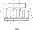
Fig 1 ] lafigure 1 est une vue de face d'un écrou selon un mode de réalisation de l'invention ; - [
Fig 2 ] lafigure 2 est une vue de dessus de l'écrou de lafigure 1 ; - [
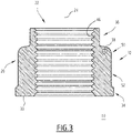
Fig 3 ] lafigure 3 est une vue en coupe de l'écrou desfigures 1 et2 ; et - [
Fig 4 ] lafigure 4 est une vue en coupe partielle d'un assemblage comprenant l'écrou desfigures 1 à 3 .
- [
Fig 1 ] thefigure 1 is a front view of a nut according to one embodiment of the invention; - [
Fig 2 ] thefigure 2 is a top view of the nut of thefigure 1 ; - [
Fig.3 ] thepicture 3 is a sectional view of the nut of thefigure 1 and2 ; and - [
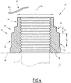
Fig 4 ] thefigure 4 is a partial cross-sectional view of an assembly including the nut of thefigures 1 to 3 .
Les
L'écrou 10 comprend un corps 20 et un perçage 22 traversant ledit corps selon un axe principal 24.The
Le corps 20 de l'écrou comprend : une face d'appui 30 ; une surface d'entraînement 32 ; une embase 34 ; une jupe de freinage 36 ; et un orifice traversant 38.The
La face d'appui 30 est destinée à prendre appui sur une surface d'une structure 40 (
La surface d'entraînement 32, ou prise de clé, s'étend autour de l'axe principal 24 et est destinée au vissage/dévissage de l'écrou au moyen d'un outil. La surface d'entraînement 32 sera décrite plus en détails ci-après.The
L'embase 34, optionnelle, est disposée entre la surface d'entraînement 32 et la face d'appui 30. L'embase a une forme sensiblement tronconique qui s'évase à partir de la surface d'entraînement 32.The
La jupe de freinage 36 prolonge la surface d'entraînement 32 par rapport à l'axe principal 24, à l'opposé de l'embase 34 ou de la face d'appui 30. Un diamètre externe 44 de la jupe de freinage 36 est inférieur ou égal, de préférence sensiblement égal, à une dimension radiale minimale de la surface d'entraînement 32. La jupe de freinage présente une forme légèrement elliptique.The
L'orifice traversant 38 s'étend sensiblement perpendiculairement à l'axe principal 24 à partir de la surface d'entraînement 32. L'orifice traversant 38 sera décrit plus en détail ci-après.Through-
Le perçage 22 est défini par une paroi interne 46 du corps 20. Ladite paroi interne est sensiblement cylindrique de révolution et munie d'un taraudage, apte à coopérer avec le filetage de la tige 12.The
La surface d'entraînement 32 va maintenant être décrite. La surface d'entraînement 32 comporte une zone supérieure 50 et une zone inférieure 52, adjacentes selon l'axe principal 24. La zone inférieure 52 est située entre la zone supérieure 50 et l'embase 34, ou la face d'appui 30 si l'embase est omise.
Un périmètre 54 de la zone inférieure 52 autour de l'axe principal 24 est plus important qu'un périmètre 56 de la zone supérieure 50. Le périmètre 54, 56 est considéré sur une section de l'écrou 10 perpendiculairement à l'axe principal 24.A
La zone supérieure 50 et la zone inférieure 52 présentent respectivement une hauteur 57 et une hauteur 58 selon l'axe principal 24.The
Comme il sera décrit ci-après, l'orifice traversant 38 est situé dans la zone supérieure 50. Comme il sera décrit ci-après, la hauteur 57 de la zone supérieure 50 est notamment choisie pour permettre l'aménagement dudit orifice traversant.As will be described below, the
Dans le mode de réalisation représenté, la surface d'entraînement 32 comporte une série de premiers pans ou méplats 60 et une série de seconds pans ou méplats 62. Les premiers 60 et seconds 62 méplats sont parallèles à l'axe principal 24.In the embodiment shown, the
Plus précisément, la surface d'entraînement 32 comporte six premiers méplats 60 de dimensions identiques, répartis angulairement de manière régulière autour de l'axe principal 24. La surface d'entraînement 32 comporte en outre six premières arêtes 64, séparant deux à deux les premiers méplats 60. De manière connue, les deux premiers méplats 60 de part et d'autre d'une première arête 64 définissent une surface convexe.More specifically, the
Les premiers méplats 60 et les premières arêtes 64 s'étendent à la fois sur la zone supérieure 50 et sur la zone inférieure 52 de la surface d'entraînement 32.The
En outre, la surface d'entraînement comporte douze seconds méplats 62 de dimensions identiques. Les seconds méplats 62 forment six paires 66 réparties angulairement de manière régulière autour de l'axe principal 24. Plus précisément, chaque paire 66 de seconds méplats 62 est disposée sensiblement au milieu d'un premier méplat 60, à égale distance des premières arêtes 64 délimitant ledit premier méplat. Chaque paire 66 de seconds méplats 62 forme une saillie radiale par rapport au premier méplat 60 correspondant.In addition, the drive surface has twelve
Les seconds méplats 62 s'étendent uniquement sur la zone inférieure 52 de la surface d'entraînement 32 et présentent une hauteur inférieure à la hauteur des premiers méplats.The
La surface d'entraînement 32 comporte en outre six deuxièmes arêtes 70. Chaque deuxième arête 70 sépare deux seconds méplats 62 d'une même paire 66, définissant une surface convexe.The
Les premières 64 et deuxièmes 70 arêtes sont tangentes à un même cylindre enveloppe 72 de base circulaire, centré sur l'axe principal 24.The first 64 and second 70 edges are tangent to the
La surface d'entraînement 32 comporte en outre douze troisièmes arêtes 74. Chaque troisième arête 74 sépare un premier 60 et un second 62 méplats adjacents, définissant une surface concave.The
Les deuxièmes 70 et troisièmes 74 arêtes s'étendent uniquement dans la zone inférieure 52 de la surface d'entraînement 32.The second 70 and third 74 ridges extend only in the
En d'autres termes, la zone supérieure 50 de la surface d'entraînement 32 est une surface à six pans, tandis que la zone inférieure 52 de ladite surface d'entraînement est une surface bi-hexagonale.In other words, the
Dans le mode de réalisation représenté, l'orifice traversant 38 s'étend entre deux premiers méplats 60 adjacents. Plus précisément, l'orifice traversant 38 s'étend entre deux extrémités 76, chaque extrémité débouchant sur l'un desdits premiers méplats 60 adjacents.In the embodiment shown, the through
Ainsi, l'orifice traversant 38 est disposé à l'écart du perçage 22 et ne débouche pas sur ledit perçage.Thus, the through
L'orifice traversant 38 est sensiblement rectiligne entre les deux extrémités 76 et s'étend dans un plan perpendiculaire à l'axe principal 24.The through
Une telle configuration est rendue possible par la surface à six pans formée par la zone supérieure 50. En effet, la surface bi-hexagonale de la zone inférieure 52 ne permet pas l'aménagement des extrémités 76 de l'orifice traversant 38.Such a configuration is made possible by the hexagonal surface formed by the
La hauteur 57 de la zone supérieure 50 est choisie pour permettre l'aménagement de l'orifice traversant 38. Par exemple, pour un écrou en inox 1100 MPa ayant un taraudage de diamètre 10/16 de pouces, une distance entre deux méplats opposés de 18,82 mm, la hauteur 57 est de 2,2 mm. Une telle hauteur 57 permet le perçage d'un orifice 38 de diamètre 1,2 mm, et une hauteur 58 de 5,4 mm pour la zone inférieure 52. Un tel écrou permet de passer un couple de 320 N.m.The
De préférence, le corps 20 comprend plusieurs orifices traversants 38 sensiblement identiques et répartis angulairement autour de l'axe principal 24. Dans le mode de réalisation représenté, le corps 20 comporte trois orifices traversants 38 identiques, sensiblement disposés aux sommets d'un triangle équilatéral centré sur l'axe principal 24.Preferably, the
Un procédé d'utilisation de l'écrou 10 et de la tige filetée 12 va maintenant être décrit. La tige 12 filetée est insérée dans un alésage de la structure 40 et l'écrou 10 est vissé sur une extrémité de ladite tige, au moyen d'un outil approprié (non représenté) coopérant avec la surface d'entraînement 32.A method of using
En particulier, la surface de la zone inférieure 52 correspond à une plus grande surface de contact avec l'outil, de sorte à transmettre un couple de serrage important.In particular, the surface of the
Dans le mode de réalisation représenté, la surface bi-hexagonale de la zone inférieure 52 coopère avec un outil (non représenté) de forme complémentaire à ladite surface. L'outil coopère également avec les premiers méplats 60 au niveau de la zone supérieure 50, à proximité des premières arêtes 64, ce qui contribue à augmenter le couple de serrage.In the embodiment shown, the bi-hexagonal surface of the
La fixation 14 étant ainsi installée, le freinage à fil est par exemple réalisé comme suit : une première extrémité 80 d'un fil métallique 82 (
L'écrou 10 est ainsi bloqué en rotation par le fil métallique 82 par rapport à la surface de la structure 40.The
Ainsi, l'écrou 10 offre un couple de serrage optimisé, un freinage performant autorisant plusieurs cycles de montage / démontage, tout en minimisant la hauteur de l'écrou et en permettant l'aménagement d'un orifice 38 pour le fil frein 82 sur la surface d'entraînement 32 dudit écrou.Thus, the
Claims (7)
Applications Claiming Priority (1)
| Application Number | Priority Date | Filing Date | Title |
|---|---|---|---|
| FR2011880A FR3116312B1 (en) | 2020-11-19 | 2020-11-19 | Lock nut and associated fixing |
Publications (2)
| Publication Number | Publication Date |
|---|---|
| EP4001676A1 true EP4001676A1 (en) | 2022-05-25 |
| EP4001676B1 EP4001676B1 (en) | 2023-08-30 |
Family
ID=74045934
Family Applications (1)
| Application Number | Title | Priority Date | Filing Date |
|---|---|---|---|
| EP21208739.9A Active EP4001676B1 (en) | 2020-11-19 | 2021-11-17 | Braking nut and associated attachment |
Country Status (4)
| Country | Link |
|---|---|
| US (1) | US12066049B2 (en) |
| EP (1) | EP4001676B1 (en) |
| CN (1) | CN114542575A (en) |
| FR (1) | FR3116312B1 (en) |
Citations (8)
| Publication number | Priority date | Publication date | Assignee | Title |
|---|---|---|---|---|
| US2686546A (en) | 1947-06-19 | 1954-08-17 | Mac Lean Fogg Lock Nut Co | Self-locking nut and process of manufacturing same |
| US2754871A (en) | 1952-09-04 | 1956-07-17 | Stoll Albert | Self-locking nut having a radially deformed thread portion and method for the production of the same |
| FR1183581A (en) | 1956-10-23 | 1959-07-09 | Nat Machine Products Company | Improvements to lock nuts |
| US3275054A (en) * | 1964-12-15 | 1966-09-27 | Standard Pressed Steel Co | Compression locking nut |
| CH425354A (en) * | 1963-01-11 | 1966-11-30 | Firth Cleveland Fastenings Ltd | Locknut, process for its manufacture and apparatus for carrying out this process |
| US3674075A (en) * | 1969-11-14 | 1972-07-04 | Shur Lok Corp | Tamper-proof two-way locking nut |
| WO2010085030A1 (en) * | 2009-01-20 | 2010-07-29 | 주식회사 호크마이엔지 | Pin for preventing a nut from being loosened, and u-bolt assembly using same |
| US20180135686A1 (en) * | 2016-11-17 | 2018-05-17 | Goodrich Corporation | Nut retention system |
Family Cites Families (15)
| Publication number | Priority date | Publication date | Assignee | Title |
|---|---|---|---|---|
| US177380A (en) * | 1876-05-16 | Improvement in nut-locks | ||
| US471608A (en) * | 1892-03-29 | Nut-lock | ||
| US653308A (en) * | 1899-10-19 | 1900-07-10 | Edwin Morse | Nut-lock. |
| US2890734A (en) * | 1956-08-02 | 1959-06-16 | John F Mullin | Wire locked bolt assemblies |
| US3140636A (en) * | 1962-09-20 | 1964-07-14 | Kaynar Mfg Co | Twelve-point nut |
| US4092080A (en) * | 1976-06-03 | 1978-05-30 | Pneumo Corporation | Anti-rotation lock for threaded connection |
| US4189976A (en) * | 1978-06-29 | 1980-02-26 | Fargo Manufacturing Company, Inc. | Dual head fastener |
| GB8722021D0 (en) * | 1987-09-18 | 1987-10-28 | British Aerospace | Lock nut assemblies |
| US5842263A (en) * | 1996-01-11 | 1998-12-01 | Westinghouse Electric Corporation | Method and manufacture of an axial tensioned bolt |
| US6150656A (en) * | 1998-12-10 | 2000-11-21 | United Technologies Corporation | Method of assembly and inspection for a gas turbine engine |
| CN202926839U (en) * | 2012-11-30 | 2013-05-08 | 浙江荣得利航空部件有限公司 | Round nut with groove |
| FR3005332B1 (en) * | 2013-05-02 | 2015-06-05 | Lisi Aerospace | POSITIVE LOCKING BOLT |
| ITUA20164439A1 (en) * | 2016-06-16 | 2017-12-16 | Bimecc Eng S P A | CONNECTION BODY, IN PARTICULAR A SCREW OR A NUT, PREFERABLY TO FIX A WHEEL, OR CIRCLE, TO A HUB OF A VEHICLE. |
| CN205895855U (en) * | 2016-08-19 | 2017-01-18 | 嵇为明 | Locking nut |
| CN209016594U (en) * | 2018-11-29 | 2019-06-21 | 威海市泓淋电力技术股份有限公司 | A kind of irradiation rubber cable part not being covered with dust |
-
2020
- 2020-11-19 FR FR2011880A patent/FR3116312B1/en active Active
-
2021
- 2021-11-05 US US17/520,605 patent/US12066049B2/en active Active
- 2021-11-17 EP EP21208739.9A patent/EP4001676B1/en active Active
- 2021-11-18 CN CN202111370367.9A patent/CN114542575A/en active Pending
Patent Citations (8)
| Publication number | Priority date | Publication date | Assignee | Title |
|---|---|---|---|---|
| US2686546A (en) | 1947-06-19 | 1954-08-17 | Mac Lean Fogg Lock Nut Co | Self-locking nut and process of manufacturing same |
| US2754871A (en) | 1952-09-04 | 1956-07-17 | Stoll Albert | Self-locking nut having a radially deformed thread portion and method for the production of the same |
| FR1183581A (en) | 1956-10-23 | 1959-07-09 | Nat Machine Products Company | Improvements to lock nuts |
| CH425354A (en) * | 1963-01-11 | 1966-11-30 | Firth Cleveland Fastenings Ltd | Locknut, process for its manufacture and apparatus for carrying out this process |
| US3275054A (en) * | 1964-12-15 | 1966-09-27 | Standard Pressed Steel Co | Compression locking nut |
| US3674075A (en) * | 1969-11-14 | 1972-07-04 | Shur Lok Corp | Tamper-proof two-way locking nut |
| WO2010085030A1 (en) * | 2009-01-20 | 2010-07-29 | 주식회사 호크마이엔지 | Pin for preventing a nut from being loosened, and u-bolt assembly using same |
| US20180135686A1 (en) * | 2016-11-17 | 2018-05-17 | Goodrich Corporation | Nut retention system |
Also Published As
| Publication number | Publication date |
|---|---|
| US12066049B2 (en) | 2024-08-20 |
| CN114542575A (en) | 2022-05-27 |
| FR3116312B1 (en) | 2022-11-18 |
| EP4001676B1 (en) | 2023-08-30 |
| US20220154759A1 (en) | 2022-05-19 |
| FR3116312A1 (en) | 2022-05-20 |
Similar Documents
| Publication | Publication Date | Title |
|---|---|---|
| EP0156681B1 (en) | Nut setting tool | |
| EP3200957B1 (en) | Dissassembly extraction system for a turbomachine | |
| EP1825151B1 (en) | Metal sheet, method for fixing said metal sheet by flow drilling and assembly comprising same | |
| EP3325827B1 (en) | Assembly comprising a locked securing stud | |
| FR2979959A1 (en) | DOUBLE CROWN LOCK WASHER | |
| FR2987881A1 (en) | SECURE CONNECTION DEVICE, IN PARTICULAR FOR PIPING, TIP FOR THIS DEVICE AND METHOD FOR MANUFACTURING AN ASSOCIATED NUT. | |
| FR2895467A1 (en) | ARRANGEMENT FOR ASSEMBLING TWO WORKPIECES THROUGH SCREWING THROUGH A SCREW-NUT ASSEMBLY | |
| EP1162376A1 (en) | Fixing member with a recess at the end of its threaded shank | |
| FR2636734A1 (en) | DEVICE FOR ATTACHING A WATER METER TO A BASE AND METHOD RELATING THERETO | |
| EP3695129B1 (en) | Grooved nut for blind fastening, rivet and assembly comprising such a nut | |
| EP3298286B1 (en) | Improved fastening element | |
| FR2959284A1 (en) | Attaching pin for cooperating with nut fixed in signaling and lightening device of vehicle using fixing device, has nibs that are circumferential with respect to longitudinal axis such that head is retained in cavity | |
| FR2897124A1 (en) | Clinch nut`s rotation immobilizing device for e.g. airplane`s jet engine, has elongated plate independent of nuts and including inner indentation cooperating with outer indentation of one nut to immobilize nut rotation relative to plate | |
| EP4001676B1 (en) | Braking nut and associated attachment | |
| EP0402198A1 (en) | Locking-nut assembly | |
| EP1605195B1 (en) | Pipe coupling system and associated method of assembly | |
| EP1231422B1 (en) | Process for making a screw unloseable, fixation collars for pipes and use of the process to manufacture the collars | |
| FR2945088A1 (en) | Blind countersunk nut system, has non- threaded skirt supporting quasi-radial face of support crown adjacent to crimping zone, and barrel constituting crimping zone on side of head and support crown of nut | |
| EP3016768B1 (en) | System for machining | |
| EP2094978B1 (en) | Nut with a deformable collar | |
| FR2751383A1 (en) | NUTS BLACK TO BE BLIND AND FINE INTO HEAD | |
| EP2239358A1 (en) | Assembly device, set of two parts assembled by such a device and warp frame of a machine for forming the shed including such a set | |
| EP3859170B1 (en) | Bolt comprising a nut and at least one washer obtained by hardening of a pasty material, method for installing said bolt and assembly comprising at least one such bolt | |
| EP0271625B1 (en) | Immovable nut | |
| FR2991410A1 (en) | Clamping screw i.e. nut tensioner, for screwing on threaded rod utilized in e.g. chemical industry, has washer interposed between clamping element and support part, and screw devices provided in recessed portions |
Legal Events
| Date | Code | Title | Description |
|---|---|---|---|
| PUAI | Public reference made under article 153(3) epc to a published international application that has entered the european phase |
Free format text: ORIGINAL CODE: 0009012 |
|
| STAA | Information on the status of an ep patent application or granted ep patent |
Free format text: STATUS: THE APPLICATION HAS BEEN PUBLISHED |
|
| AK | Designated contracting states |
Kind code of ref document: A1 Designated state(s): AL AT BE BG CH CY CZ DE DK EE ES FI FR GB GR HR HU IE IS IT LI LT LU LV MC MK MT NL NO PL PT RO RS SE SI SK SM TR |
|
| STAA | Information on the status of an ep patent application or granted ep patent |
Free format text: STATUS: REQUEST FOR EXAMINATION WAS MADE |
|
| 17P | Request for examination filed |
Effective date: 20221114 |
|
| RBV | Designated contracting states (corrected) |
Designated state(s): AL AT BE BG CH CY CZ DE DK EE ES FI FR GB GR HR HU IE IS IT LI LT LU LV MC MK MT NL NO PL PT RO RS SE SI SK SM TR |
|
| GRAP | Despatch of communication of intention to grant a patent |
Free format text: ORIGINAL CODE: EPIDOSNIGR1 |
|
| STAA | Information on the status of an ep patent application or granted ep patent |
Free format text: STATUS: GRANT OF PATENT IS INTENDED |
|
| RIC1 | Information provided on ipc code assigned before grant |
Ipc: F16B 39/284 20060101ALI20230310BHEP Ipc: F16B 39/10 20060101AFI20230310BHEP |
|
| INTG | Intention to grant announced |
Effective date: 20230406 |
|
| GRAS | Grant fee paid |
Free format text: ORIGINAL CODE: EPIDOSNIGR3 |
|
| GRAA | (expected) grant |
Free format text: ORIGINAL CODE: 0009210 |
|
| STAA | Information on the status of an ep patent application or granted ep patent |
Free format text: STATUS: THE PATENT HAS BEEN GRANTED |
|
| AK | Designated contracting states |
Kind code of ref document: B1 Designated state(s): AL AT BE BG CH CY CZ DE DK EE ES FI FR GB GR HR HU IE IS IT LI LT LU LV MC MK MT NL NO PL PT RO RS SE SI SK SM TR |
|
| REG | Reference to a national code |
Ref country code: GB Ref legal event code: FG4D Free format text: NOT ENGLISH |
|
| REG | Reference to a national code |
Ref country code: CH Ref legal event code: EP |
|
| REG | Reference to a national code |
Ref country code: DE Ref legal event code: R096 Ref document number: 602021004709 Country of ref document: DE |
|
| REG | Reference to a national code |
Ref country code: IE Ref legal event code: FG4D Free format text: LANGUAGE OF EP DOCUMENT: FRENCH |
|
| REG | Reference to a national code |
Ref country code: LT Ref legal event code: MG9D |
|
| REG | Reference to a national code |
Ref country code: NL Ref legal event code: MP Effective date: 20230830 |
|
| REG | Reference to a national code |
Ref country code: AT Ref legal event code: MK05 Ref document number: 1605789 Country of ref document: AT Kind code of ref document: T Effective date: 20230830 |
|
| PG25 | Lapsed in a contracting state [announced via postgrant information from national office to epo] |
Ref country code: GR Free format text: LAPSE BECAUSE OF FAILURE TO SUBMIT A TRANSLATION OF THE DESCRIPTION OR TO PAY THE FEE WITHIN THE PRESCRIBED TIME-LIMIT Effective date: 20231201 |
|
| PG25 | Lapsed in a contracting state [announced via postgrant information from national office to epo] |
Ref country code: IS Free format text: LAPSE BECAUSE OF FAILURE TO SUBMIT A TRANSLATION OF THE DESCRIPTION OR TO PAY THE FEE WITHIN THE PRESCRIBED TIME-LIMIT Effective date: 20231230 |
|
| PG25 | Lapsed in a contracting state [announced via postgrant information from national office to epo] |
Ref country code: SE Free format text: LAPSE BECAUSE OF FAILURE TO SUBMIT A TRANSLATION OF THE DESCRIPTION OR TO PAY THE FEE WITHIN THE PRESCRIBED TIME-LIMIT Effective date: 20230830 Ref country code: RS Free format text: LAPSE BECAUSE OF FAILURE TO SUBMIT A TRANSLATION OF THE DESCRIPTION OR TO PAY THE FEE WITHIN THE PRESCRIBED TIME-LIMIT Effective date: 20230830 Ref country code: NO Free format text: LAPSE BECAUSE OF FAILURE TO SUBMIT A TRANSLATION OF THE DESCRIPTION OR TO PAY THE FEE WITHIN THE PRESCRIBED TIME-LIMIT Effective date: 20231130 Ref country code: LV Free format text: LAPSE BECAUSE OF FAILURE TO SUBMIT A TRANSLATION OF THE DESCRIPTION OR TO PAY THE FEE WITHIN THE PRESCRIBED TIME-LIMIT Effective date: 20230830 Ref country code: LT Free format text: LAPSE BECAUSE OF FAILURE TO SUBMIT A TRANSLATION OF THE DESCRIPTION OR TO PAY THE FEE WITHIN THE PRESCRIBED TIME-LIMIT Effective date: 20230830 Ref country code: IS Free format text: LAPSE BECAUSE OF FAILURE TO SUBMIT A TRANSLATION OF THE DESCRIPTION OR TO PAY THE FEE WITHIN THE PRESCRIBED TIME-LIMIT Effective date: 20231230 Ref country code: HR Free format text: LAPSE BECAUSE OF FAILURE TO SUBMIT A TRANSLATION OF THE DESCRIPTION OR TO PAY THE FEE WITHIN THE PRESCRIBED TIME-LIMIT Effective date: 20230830 Ref country code: GR Free format text: LAPSE BECAUSE OF FAILURE TO SUBMIT A TRANSLATION OF THE DESCRIPTION OR TO PAY THE FEE WITHIN THE PRESCRIBED TIME-LIMIT Effective date: 20231201 Ref country code: FI Free format text: LAPSE BECAUSE OF FAILURE TO SUBMIT A TRANSLATION OF THE DESCRIPTION OR TO PAY THE FEE WITHIN THE PRESCRIBED TIME-LIMIT Effective date: 20230830 Ref country code: AT Free format text: LAPSE BECAUSE OF FAILURE TO SUBMIT A TRANSLATION OF THE DESCRIPTION OR TO PAY THE FEE WITHIN THE PRESCRIBED TIME-LIMIT Effective date: 20230830 |
|
| PGFP | Annual fee paid to national office [announced via postgrant information from national office to epo] |
Ref country code: FR Payment date: 20231124 Year of fee payment: 3 Ref country code: DE Payment date: 20231107 Year of fee payment: 3 |
|
| PG25 | Lapsed in a contracting state [announced via postgrant information from national office to epo] |
Ref country code: PL Free format text: LAPSE BECAUSE OF FAILURE TO SUBMIT A TRANSLATION OF THE DESCRIPTION OR TO PAY THE FEE WITHIN THE PRESCRIBED TIME-LIMIT Effective date: 20230830 Ref country code: NL Free format text: LAPSE BECAUSE OF FAILURE TO SUBMIT A TRANSLATION OF THE DESCRIPTION OR TO PAY THE FEE WITHIN THE PRESCRIBED TIME-LIMIT Effective date: 20230830 |
|
| PG25 | Lapsed in a contracting state [announced via postgrant information from national office to epo] |
Ref country code: ES Free format text: LAPSE BECAUSE OF FAILURE TO SUBMIT A TRANSLATION OF THE DESCRIPTION OR TO PAY THE FEE WITHIN THE PRESCRIBED TIME-LIMIT Effective date: 20230830 |
|
| PG25 | Lapsed in a contracting state [announced via postgrant information from national office to epo] |
Ref country code: SM Free format text: LAPSE BECAUSE OF FAILURE TO SUBMIT A TRANSLATION OF THE DESCRIPTION OR TO PAY THE FEE WITHIN THE PRESCRIBED TIME-LIMIT Effective date: 20230830 Ref country code: RO Free format text: LAPSE BECAUSE OF FAILURE TO SUBMIT A TRANSLATION OF THE DESCRIPTION OR TO PAY THE FEE WITHIN THE PRESCRIBED TIME-LIMIT Effective date: 20230830 Ref country code: ES Free format text: LAPSE BECAUSE OF FAILURE TO SUBMIT A TRANSLATION OF THE DESCRIPTION OR TO PAY THE FEE WITHIN THE PRESCRIBED TIME-LIMIT Effective date: 20230830 Ref country code: EE Free format text: LAPSE BECAUSE OF FAILURE TO SUBMIT A TRANSLATION OF THE DESCRIPTION OR TO PAY THE FEE WITHIN THE PRESCRIBED TIME-LIMIT Effective date: 20230830 Ref country code: DK Free format text: LAPSE BECAUSE OF FAILURE TO SUBMIT A TRANSLATION OF THE DESCRIPTION OR TO PAY THE FEE WITHIN THE PRESCRIBED TIME-LIMIT Effective date: 20230830 Ref country code: CZ Free format text: LAPSE BECAUSE OF FAILURE TO SUBMIT A TRANSLATION OF THE DESCRIPTION OR TO PAY THE FEE WITHIN THE PRESCRIBED TIME-LIMIT Effective date: 20230830 Ref country code: SK Free format text: LAPSE BECAUSE OF FAILURE TO SUBMIT A TRANSLATION OF THE DESCRIPTION OR TO PAY THE FEE WITHIN THE PRESCRIBED TIME-LIMIT Effective date: 20230830 Ref country code: PT Free format text: LAPSE BECAUSE OF FAILURE TO SUBMIT A TRANSLATION OF THE DESCRIPTION OR TO PAY THE FEE WITHIN THE PRESCRIBED TIME-LIMIT Effective date: 20240102 |
|
| PG25 | Lapsed in a contracting state [announced via postgrant information from national office to epo] |
Ref country code: IT Free format text: LAPSE BECAUSE OF FAILURE TO SUBMIT A TRANSLATION OF THE DESCRIPTION OR TO PAY THE FEE WITHIN THE PRESCRIBED TIME-LIMIT Effective date: 20230830 |
|
| REG | Reference to a national code |
Ref country code: DE Ref legal event code: R097 Ref document number: 602021004709 Country of ref document: DE |
|
| PG25 | Lapsed in a contracting state [announced via postgrant information from national office to epo] |
Ref country code: MC Free format text: LAPSE BECAUSE OF FAILURE TO SUBMIT A TRANSLATION OF THE DESCRIPTION OR TO PAY THE FEE WITHIN THE PRESCRIBED TIME-LIMIT Effective date: 20230830 |
|
| PLBE | No opposition filed within time limit |
Free format text: ORIGINAL CODE: 0009261 |
|
| STAA | Information on the status of an ep patent application or granted ep patent |
Free format text: STATUS: NO OPPOSITION FILED WITHIN TIME LIMIT |
|
| PG25 | Lapsed in a contracting state [announced via postgrant information from national office to epo] |
Ref country code: LU Free format text: LAPSE BECAUSE OF NON-PAYMENT OF DUE FEES Effective date: 20231117 |
|
| PG25 | Lapsed in a contracting state [announced via postgrant information from national office to epo] |
Ref country code: MC Free format text: LAPSE BECAUSE OF FAILURE TO SUBMIT A TRANSLATION OF THE DESCRIPTION OR TO PAY THE FEE WITHIN THE PRESCRIBED TIME-LIMIT Effective date: 20230830 Ref country code: LU Free format text: LAPSE BECAUSE OF NON-PAYMENT OF DUE FEES Effective date: 20231117 Ref country code: SI Free format text: LAPSE BECAUSE OF FAILURE TO SUBMIT A TRANSLATION OF THE DESCRIPTION OR TO PAY THE FEE WITHIN THE PRESCRIBED TIME-LIMIT Effective date: 20230830 |
|
| REG | Reference to a national code |
Ref country code: BE Ref legal event code: MM Effective date: 20231130 |
|
| 26N | No opposition filed |
Effective date: 20240603 |