EP4001671B1 - Hydraulikkreislauf mit kombinierter kompensations - und energierückgewinnungsfuntion - Google Patents
Hydraulikkreislauf mit kombinierter kompensations - und energierückgewinnungsfuntion Download PDFInfo
- Publication number
- EP4001671B1 EP4001671B1 EP21208732.4A EP21208732A EP4001671B1 EP 4001671 B1 EP4001671 B1 EP 4001671B1 EP 21208732 A EP21208732 A EP 21208732A EP 4001671 B1 EP4001671 B1 EP 4001671B1
- Authority
- EP
- European Patent Office
- Prior art keywords
- hydraulic
- hydraulic circuit
- pressure
- signal
- reduced pressure
- Prior art date
- Legal status (The legal status is an assumption and is not a legal conclusion. Google has not performed a legal analysis and makes no representation as to the accuracy of the status listed.)
- Active
Links
Images


Classifications
-
- F—MECHANICAL ENGINEERING; LIGHTING; HEATING; WEAPONS; BLASTING
- F15—FLUID-PRESSURE ACTUATORS; HYDRAULICS OR PNEUMATICS IN GENERAL
- F15B—SYSTEMS ACTING BY MEANS OF FLUIDS IN GENERAL; FLUID-PRESSURE ACTUATORS, e.g. SERVOMOTORS; DETAILS OF FLUID-PRESSURE SYSTEMS, NOT OTHERWISE PROVIDED FOR
- F15B21/00—Common features of fluid actuator systems; Fluid-pressure actuator systems or details thereof, not covered by any other group of this subclass
- F15B21/14—Energy-recuperation means
-
- F—MECHANICAL ENGINEERING; LIGHTING; HEATING; WEAPONS; BLASTING
- F15—FLUID-PRESSURE ACTUATORS; HYDRAULICS OR PNEUMATICS IN GENERAL
- F15B—SYSTEMS ACTING BY MEANS OF FLUIDS IN GENERAL; FLUID-PRESSURE ACTUATORS, e.g. SERVOMOTORS; DETAILS OF FLUID-PRESSURE SYSTEMS, NOT OTHERWISE PROVIDED FOR
- F15B2211/00—Circuits for servomotor systems
- F15B2211/40—Flow control
- F15B2211/415—Flow control characterised by the connections of the flow control means in the circuit
- F15B2211/41554—Flow control characterised by the connections of the flow control means in the circuit being connected to a return line and a directional control valve
-
- F—MECHANICAL ENGINEERING; LIGHTING; HEATING; WEAPONS; BLASTING
- F15—FLUID-PRESSURE ACTUATORS; HYDRAULICS OR PNEUMATICS IN GENERAL
- F15B—SYSTEMS ACTING BY MEANS OF FLUIDS IN GENERAL; FLUID-PRESSURE ACTUATORS, e.g. SERVOMOTORS; DETAILS OF FLUID-PRESSURE SYSTEMS, NOT OTHERWISE PROVIDED FOR
- F15B2211/00—Circuits for servomotor systems
- F15B2211/40—Flow control
- F15B2211/42—Flow control characterised by the type of actuation
- F15B2211/428—Flow control characterised by the type of actuation actuated by fluid pressure
-
- F—MECHANICAL ENGINEERING; LIGHTING; HEATING; WEAPONS; BLASTING
- F15—FLUID-PRESSURE ACTUATORS; HYDRAULICS OR PNEUMATICS IN GENERAL
- F15B—SYSTEMS ACTING BY MEANS OF FLUIDS IN GENERAL; FLUID-PRESSURE ACTUATORS, e.g. SERVOMOTORS; DETAILS OF FLUID-PRESSURE SYSTEMS, NOT OTHERWISE PROVIDED FOR
- F15B2211/00—Circuits for servomotor systems
- F15B2211/50—Pressure control
- F15B2211/505—Pressure control characterised by the type of pressure control means
- F15B2211/50554—Pressure control characterised by the type of pressure control means the pressure control means controlling a pressure downstream of the pressure control means, e.g. pressure reducing valve
-
- F—MECHANICAL ENGINEERING; LIGHTING; HEATING; WEAPONS; BLASTING
- F15—FLUID-PRESSURE ACTUATORS; HYDRAULICS OR PNEUMATICS IN GENERAL
- F15B—SYSTEMS ACTING BY MEANS OF FLUIDS IN GENERAL; FLUID-PRESSURE ACTUATORS, e.g. SERVOMOTORS; DETAILS OF FLUID-PRESSURE SYSTEMS, NOT OTHERWISE PROVIDED FOR
- F15B2211/00—Circuits for servomotor systems
- F15B2211/50—Pressure control
- F15B2211/52—Pressure control characterised by the type of actuation
-
- F—MECHANICAL ENGINEERING; LIGHTING; HEATING; WEAPONS; BLASTING
- F15—FLUID-PRESSURE ACTUATORS; HYDRAULICS OR PNEUMATICS IN GENERAL
- F15B—SYSTEMS ACTING BY MEANS OF FLUIDS IN GENERAL; FLUID-PRESSURE ACTUATORS, e.g. SERVOMOTORS; DETAILS OF FLUID-PRESSURE SYSTEMS, NOT OTHERWISE PROVIDED FOR
- F15B2211/00—Circuits for servomotor systems
- F15B2211/60—Circuit components or control therefor
- F15B2211/605—Load sensing circuits
-
- F—MECHANICAL ENGINEERING; LIGHTING; HEATING; WEAPONS; BLASTING
- F15—FLUID-PRESSURE ACTUATORS; HYDRAULICS OR PNEUMATICS IN GENERAL
- F15B—SYSTEMS ACTING BY MEANS OF FLUIDS IN GENERAL; FLUID-PRESSURE ACTUATORS, e.g. SERVOMOTORS; DETAILS OF FLUID-PRESSURE SYSTEMS, NOT OTHERWISE PROVIDED FOR
- F15B2211/00—Circuits for servomotor systems
- F15B2211/60—Circuit components or control therefor
- F15B2211/635—Circuits providing pilot pressure to pilot pressure-controlled fluid circuit elements
- F15B2211/6355—Circuits providing pilot pressure to pilot pressure-controlled fluid circuit elements having valve means
-
- F—MECHANICAL ENGINEERING; LIGHTING; HEATING; WEAPONS; BLASTING
- F15—FLUID-PRESSURE ACTUATORS; HYDRAULICS OR PNEUMATICS IN GENERAL
- F15B—SYSTEMS ACTING BY MEANS OF FLUIDS IN GENERAL; FLUID-PRESSURE ACTUATORS, e.g. SERVOMOTORS; DETAILS OF FLUID-PRESSURE SYSTEMS, NOT OTHERWISE PROVIDED FOR
- F15B2211/00—Circuits for servomotor systems
- F15B2211/60—Circuit components or control therefor
- F15B2211/665—Methods of control using electronic components
- F15B2211/6658—Control using different modes, e.g. four-quadrant-operation, working mode and transportation mode
-
- F—MECHANICAL ENGINEERING; LIGHTING; HEATING; WEAPONS; BLASTING
- F15—FLUID-PRESSURE ACTUATORS; HYDRAULICS OR PNEUMATICS IN GENERAL
- F15B—SYSTEMS ACTING BY MEANS OF FLUIDS IN GENERAL; FLUID-PRESSURE ACTUATORS, e.g. SERVOMOTORS; DETAILS OF FLUID-PRESSURE SYSTEMS, NOT OTHERWISE PROVIDED FOR
- F15B2211/00—Circuits for servomotor systems
- F15B2211/60—Circuit components or control therefor
- F15B2211/67—Methods for controlling pilot pressure
-
- F—MECHANICAL ENGINEERING; LIGHTING; HEATING; WEAPONS; BLASTING
- F15—FLUID-PRESSURE ACTUATORS; HYDRAULICS OR PNEUMATICS IN GENERAL
- F15B—SYSTEMS ACTING BY MEANS OF FLUIDS IN GENERAL; FLUID-PRESSURE ACTUATORS, e.g. SERVOMOTORS; DETAILS OF FLUID-PRESSURE SYSTEMS, NOT OTHERWISE PROVIDED FOR
- F15B2211/00—Circuits for servomotor systems
- F15B2211/80—Other types of control related to particular problems or conditions
- F15B2211/88—Control measures for saving energy
Definitions
- the invention falls within the field of hydraulic distributors intended for managing hydraulic actuators by using pressure compensation devices.
- An excessive choking of the in/out meter area due to the intervention of the local compensators results in an energy dissipation that is discharged through the fluid in the form of heat.
- Such document describes a hydraulic circuit comprising a compensator arranged on the drain branch of a control valve for a single-effect actuation intended for lifting a load.
- An outlet branch from the compensator is connected to the accumulator, to which a flow of fluid is sent under certain operating conditions.
- the technical problem at the basis of the present invention is to make available a hydraulic circuit that is structurally and functionally conceived to overcome, at least in part, one or more of the limitations disclosed above with reference to the mentioned known technique.
- the object of the present invention is to make available to the known art a hydraulic circuit provided with a three-way compensator capable of combining, with the usual flow adjustment functions that are typical of compensators, the ability to manage a primary flow with the aim of saving energy within the realm of a simple, rational and affordable solution.
- a further object is to make available a hydraulic circuit that allows the energy that normally is dissipated in the case of dragging loads or more generally, of inertial loads acting in the same direction as the movement, to be at least partially recovered.
- Yet another aim of the invention is to provide a hydraulic circuit that is suitable for use in excavators and, in general, in modern off-highway applications.
- the hydraulic circuit of the present invention comprises a hydraulic distribution module with one or more working sections, and at least one compensated adjustment device, capable of managing a priority flow aimed at energy saving logic.
- the distribution module includes at least one spool intended to operate at least one hydraulic utility such as a hydraulic actuator.
- the circuit comprises a supply unit, preferably with variable flow rate or pressure, configured to supply a flow of operating fluid at a working pressure to the spool delivery channel, for activating the hydraulic utility.
- the compensated adjustment device is connected at its first channel to the spool discharge branch and connected to discharge at a second channel.
- the compensated adjustment device is piloted on one side by the local load sensing signal and on the other side by the maximum load sensing signal.
- the maximum load sensing signal corresponds to that of the highest pressure working section.
- compensated adjustment device is connected to the energy recovery device which is responsible for implementing energy-saving logics, for example based on a regeneration system.
- the circuit of the present invention is also configured to receive a reduced pressure signal, which enables the compensated adjustment device to be activated in the case of driving and inertial loads acting in the same direction as the movement.
- the reduced pressure signal preferably has a lower value than the working pressure and acts on the compensated adjustment device of the maximum load sensing signal.
- the reduced pressure value can be comprised between 15 and 20 bar, for example.
- the compensated adjustment device is switched to direct the discharge flow from the spool towards the energy recovery device.
- the reduced pressure signal can be generated from the working pressure by means of a pressure reducing valve.
- the pressure reducing valve can be connected to a delivery line coming from the supply unit.
- the reduced pressure signal can be provided by an external source of low-pressure auxiliary operating fluid.
- the reduced pressure signal adopted in the circuit of the present invention can be easily obtained either by using the same flow rate of operating fluid already intended to activate the different sections, or by a simple connection to an external low pressure source.
- low pressure means a pressure significantly lower than that required for the operation of the hydraulic utilities envisaged by the application, for example a value comprised between 15 and 20 bar, as specified above. However, it is clear that this value will be linked to the effective application of the hydraulic circuit.
- the passage of the reduced pressure towards the relevant piloting line of the compensated adjustment device is adjusted by means of a selection device which may comprise a two-way valve.
- the two-way valve, or other selection device used is electrically controlled.
- the spool will discharge the reduced pressure under specific conditions.
- the spool may include an additional way connected via a respective line to the reduced pressure.
- the spool is configured to close this additional way or connect it to a drain depending on its operational position.
- the spool can be activated via electro-hydraulic controls. It will be appreciated, however, that different activations can also be provided, e.g. mechanical, hydraulic and electromechanical.
- the hydraulic circuit comprises a choke arranged in a shunt from the first piloting line towards the discharge.
- the presence of the choke prevents the accumulation of pressure on the maximum LS signal line and ensures rapid depressurisation of the system.
- the two-way valve, or other selection device used can be operated electrically, hydraulically or mechanically.
- a control unit which, in the presence of a dragging load acting on the actuator of the working section, sends an electrical, hydraulic or mechanical command to switch the valve.
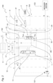
- a hydraulic circuit according to the present invention is shown as a whole with numeral 100.
- the hydraulic circuit 100 of the present invention has the function of compensation and energy recovery.
- the hydraulic circuit 100 is preferably supplied by means of a supply unit 101.
- the supply unit 101 may be of the variable flow or pressure type, as in the example embodiment shown in the figure. However, other solutions may be provided for the adjustment of the power unit 101.
- the supply unit 101 may comprise a variable displacement pump which adjusts the flow rate based on the pressure of the highest pressure utility among those supplied by the supply unit.
- the example in figure 4 illustrates, for example, the hydraulic circuit 100 in the case where the supply unit 101 is intended to supply two hydraulic utilities U1, U2. It should be noted that there may also be a larger number of utilities, as indicated above.
- hydraulic utility U1 can for example be represented by the operation of a double-acting hydraulic actuator or any other hydraulic apparatus. It will be appreciated that the same inventive concepts set out in connection with the present invention are also applicable to other solutions, such as a hydraulic motor. For this reason, the term "hydraulic utility" is used below to refer to any hydraulic apparatus intended to be operated via a hydraulic circuit with one or more working sections.
- the hydraulic circuit 100 comprises a distribution module 102 that receives a flow rate of operating fluid from the supply unit 101 to distribute the fluid towards the hydraulic utility U1.
- a distribution module 102 that receives a flow rate of operating fluid from the supply unit 101 to distribute the fluid towards the hydraulic utility U1.
- the distribution module comprises a spool 1 for operating the hydraulic utility.
- a spool 1 for operating the hydraulic utility.
- the spool 1 defines a main delivery channel 11, which receives a flow of fluid from the supply unit 101, and a discharge channel 13 through which the fluid exiting the hydraulic utility U1, for example from the hydraulic actuator illustrated in the example embodiment of the figures, transits.
- the spool comprises a delivery notch 14 through which the flow of fluid supplied by the supply unit 101 transits.
- the circuit comprises a secondary delivery branch 12, to which the main delivery branch 11 is connected.
- a check valve 15 is preferably located between the secondary pressure branch 12 and the main pressure branch 11.
- the delivery notch 14 is therefore advantageously configured such that the operating fluid transiting between the main delivery branch 11 and the secondary delivery branch 12 passes through the notch 14.
- the hydraulic circuit 100 of the present invention further comprises one or more three-way compensated adjustment devices 2, preferably in a number equal to the working sections of the circuit, and whose features will be explained in detail below.
- the compensated three-way adjustment device 2 is connected, at a first channel thereof 21, to the discharge branch 13 of the spool 1 and connected to discharge T at a second channel 22.
- a third channel 23 of the three-way compensated adjustment device 2 is connected to an energy recovery device 103, the latter being illustrated in more detail below.
- the adjustment device 2 can be adjusted, preferably by continuous adjustment, between three adjustment positions implemented via specific piloting signals. It will be understood that the term continuous adjustment means the ability to move gradually and continuously between positions. In other words, the opening and closing of a window of the adjustment device 2 takes place in a gradual manner, passing progressively from the closed to the open condition.
- the piloting signals are provided by a respective first piloting channel 31 through which a Maximum Load Sensing signal P LSmax acts on a first side 2A of the adjustment device 2, and by a second piloting channel 32 through which a Local Load Sensing signal P LSloc acts on a second side 2B. It will be appreciated that the areas defined by sides 2A and 2B respectively are preferably equal.
- an additional force may also act, preferably defined by the action of a spring, or an equivalent elastic element 33.
- additional force can be provided alternatively or additionally by means of hydraulic piloting acting on one of the sides of the adjustment device.
- a connecting channel 24 may be provided which sends the signal taken from the second piloting channel 32 to the first piloting channel 31, passing through a relative notch 25 and a non-return valve 25A.
- the pressure of the maximum Load Sensing signal P LSmax is advantageously characteristic of the pressure of the higher pressure hydraulic utility if more than one section is present. Obviously, if there is only one utility U1, the pressure of the maximum Load Sensing signal P LSmax can correspond to that of such utility.
- the pressure of the local Load Sensing signal P LSloc is taken from a section 11' through which the working fluid is supplied from the supply unit 101 to the hydraulic utility U1.
- the second piloting channel 32 is for this purpose connected to the section 11' of the main delivery branch 11 downstream of the spool 1 from which the Local Load Sensing signal P LSloc is supplied.
- the Load Sensing signals from the various sections can be selected by selector valves, not shown in the diagram, so that the highest is taken to the supply unit, which in turn generates a supply pressure of a value equal to the Maximum Load Sensing plus a preset margin.
- the signals can be selected by the compensated adjustment controller 2.
- the circuit may also include an optional valve device 17 which allows the pressure value on one or both of the two channels A, B of the actuator of the hydraulic utility U1 to be limited according to the movement of the actuator and any load present.
- a pressure limiting valve 16 located on the signal line LS MAX allows the maximum pressure value of the system to be defined.
- the adjustment device 2 is kept normally open and, in a first position, is configured so that the first channel 10 is in connection with the energy recovery device 103 and a discharge line T. In this condition, the flow is therefore preferentially sent to the discharge T.
- the adjustment device starts moving towards a second position.
- the connection to the recovery device 103 is maintained via the third channel 23.
- the connection to the discharge T is instead throttled in this second position. In this way, the hydraulic flow is sent as a priority to the energy recovery device 103.
- the drawer In the third position, the drawer completely closes all passages or throttles them to the point of ensuring the necessary pressure for all operating conditions, preventing the flow from being directed to the discharge or to the energy recovery device 103.
- the fluid flow to the discharge channel 22 and to the energy recovery device 103 can be prevented or the fluid flow to the second channel 23 can be sent by means of a choked passage so as to guarantee the necessary pressure for all the operating conditions.
- the device 2 is configured to move gradually between positions, closing the channels, or throttling them, in a progressive manner.
- the flow rate outlet from the energy recovery line may be redirected, possibly through a check valve to the energy recovery device(s) 103 in order to store potential hydraulic energy to be used again in new active working steps.
- the adjustment device 2 may be configured so as to intervene if the utility activated by the spool is subjected to an inertial load F that acts in the same direction as the displacement of the actuator.
- the present invention provides for a selection section 104 by means of which a reduced pressure signal P rid is introduced into the circuit to be sent to the first piloting line 31 under predetermined conditions.
- these conditions are determined by lowering the pressure of the maximum load sensing signal P LSmax below a predetermined pressure value, which may correspond to the reduced pressure value P rid .
- the reduced pressure P rid normally has a lower value than the working pressure P and, in some embodiments, can have a value comprised between 15 and 20 bar. Obviously, different values may also be envisaged depending on the specific type of application.
- the adjustment device 2 moves between its positions according to the difference between the Maximum Load Sensing P LSmax and Local Load Sensing P LSloc signals, i.e. the signals present on sides 2A and 2B of the device 2, respectively.
- the possibility of providing the reduced pressure signal Prid makes it possible to prevent the pressure on the side 2B of the Maximum Load Sensing signal P LSmax from falling below a predetermined value, defined by the reduced pressure. This allows the adjustment device 2 to be properly controlled, even under load conditions, for example, where there is low pressure and a high flow rate in the section.
- the adjustment device 2 may be configured in such a way that the flow is sent in a priority manner, via the channel 23, to the energy recovery device 103, at least as far as this is able to accept operating fluid.
- the adjustment device 2 Based on the difference between the Maximum Load Sensing signal P LSmax and the Local Load Sensing signal P LSloc , the adjustment device 2 changes its position in such a way that it performs an adjustment action, i.e. it directs the operating fluid flow in such a way that a balanced situation is restored.
- the recovery device 2 tends to close the passage of operating fluid to the discharge and to throttle or close the passage towards the recovery device 103.
- the adjustment device 2 tends to open both the passage to discharge and the passage towards the recovery device, id the fluid will be sent in priority to discharge.
- the adjustment device 2 gradually moves to a position such that the fluid is sent to the recovery device 103, at least as long as the operating conditions of the latter permit it.
- the reduced pressure signal tends to be copied onto the local load sensing signal P LSloc to restore a balanced situation.
- the reduced pressure signal Prid is supplied to the Maximum Load Sensing P LSmax line via a corresponding channel 41.
- a check valve 42 located along the channel 41 may be provided.
- the sending of the reduced pressure to the first piloting line 31 is adjusted by means of a two-way valve 3.
- the non-return valve 42 can in this case be interposed between the two-way valve 3 and the Maximum Load Sensing signal P LSmax line.
- the two-way valve 3 may be controlled electrically, hydraulically or mechanically in the presence of a dragging load F acting on the actuator of the hydraulic utility U1 in such a way that it switches to a position in which the reduced pressure fluid Prid is sent towards the first piloting line 31.
- the valve 3 can be activated whenever the spool 1 is piloted to perform a movement with a dragging load, such as lowering an excavator arm.
- the two-way valve can be activated by a mechanical device or hydraulic pilot control.
- control unit 7 which is responsible for adjusting the activation of the valve 3 according to the position of the spool 1.
- valve can be replaced by different selection devices 3 designed to send the flow at reduced pressure under predetermined conditions.
- the spool 1 includes an additional way 4' connected via a respective line to the reduced pressure Prid.
- the spool 1 is therefore configured to close this additional way 4' or connect it to a drainage outlet D depending on its operating position, in a manner conceptually similar to that described in relation to the embodiment of figure 1 .
- the selection section 104 comprises a pressure reducing valve 4 configured to reduce the working pressure P to the reduced pressure Prid.
- the pressure reducing valve 4 is connected to a delivery line 101A of the supply unit 101.
- the pressure reducing valve 4 is set in such a way that the outlet pressure is the reduced pressure Prid intended for the system, i.e. in the example described above a pressure comprised between 15 and 20 bar.
- the reduced pressure Prid can also be used to activate the spool 1.
- a control line 61 may be provided through which the reduced pressure Prid is supplied to the electro-hydraulic controls 6 for operating the spool 1.
- control line 61 is therefore advantageously connected to the valve 4.
- the energy recovery device 103 may comprise at least one accumulator that allows the hydraulic fluid to be stored in the cases in which the working conditions of the circuit allow it. It should be noted, however, that energy recovery within the scope of the present invention does not necessarily involve an accumulator.
- the energy recovery device 103 may be configured so as to reintroduce potential hydraulic energy back into the distribution module 102 that feeds the working sections, in other words, thus providing the feeding line of the hydraulic module with hydraulic fluid, for example collected in the accumulator.
- the energy recovery device 103 may be configured so as to transfer said hydraulic fluid to a system or device for transforming potential hydraulic energy provided by said hydraulic fluid into another form of energy.
- the device for transforming potential hydraulic energy may be depicted by an alternator, generator or a flywheel.
- the selection section 104 is configured to receive said reduced pressure Prid from an external source 8 of low pressure auxiliary operating fluid.
- the embodiment illustrated in figure 3 may also provide for reduced pressure to be supplied by the external source 8.
- the reduced pressure Prid is also used in the additional way 4' of the spool 1 and, for this purpose, a narrowing 81 may also be provided in the selection section 104 along the line connected to the external source 8. It will be appreciated that the narrowing 81 prevents excessive fluid flow in the piloting channel, thus preventing saturation of the circuit.
- circuit of the present invention enables the functions of compensation and energy recovery to be carried out effectively, even in the case of inertial loads acting in the same direction as the movement and such as to generate higher speeds than those generated by the flow rate at the outlet.
Landscapes
- Engineering & Computer Science (AREA)
- Physics & Mathematics (AREA)
- Fluid Mechanics (AREA)
- Mechanical Engineering (AREA)
- General Engineering & Computer Science (AREA)
- Chemical & Material Sciences (AREA)
- Analytical Chemistry (AREA)
- Fluid-Pressure Circuits (AREA)
Claims (15)
- Hydraulikkreislauf (100) mit einer Kompensations- und Energierückgewinnungsfunktion, umfassend:• ein Verteilermodul (102) zur Verteilung von Hydraulikflüssigkeit, das mindestens eine Spule (1) zur Betätigung mindestens eines hydraulischen Verbrauchers (U1), z.B. eines hydraulischen Aktuators, einschließt, wobei:o Die Spule (1) ist so konfiguriert, dass sie im Verteilermodul (102) einen Hauptförderzweig (11) und einen Auslasszweig (13) definiert,• eine Versorgungseinheit, die so konfiguriert ist, dass sie dem Hauptförderzweig (11) einen Durchfluss von Betriebsflüssigkeit mit einem Arbeitsdruck (P) zuführt, um den hydraulischen Verbraucher (U1) zu aktivieren;• eine kompensierte Dreiwege-Einstellvorrichtung (2), die an einem ersten Kanal (21) mit dem Auslasszweig (13) der Spule (1) und an einem zweiten Kanal (22) mit dem Auslass (T) verbunden ist;∘ die kompensierte Dreiwege-Einstellvorrichtung (2) ferner eine erste Steuerleitung (31) und eine zweite Steuerleitung (32) umfasst, die so konfiguriert sind, dass über die erste Steuerleitung (31) ein Maximum Load Sensing (PLSmax)-Steuersignal auf eine erste Seite (2A) der Einstellvorrichtung (2) wirkt, das für den Druck des hydraulischen Verbrauchers (U1) charakteristisch ist, wenn es einen einzelnen Abschnitt gibt, oder des hydraulischen Verbrauchers mit höherem Druck, wenn mehr als ein hydraulischer Verbraucher vorhanden ist, und so, dass über die zweite Steuerleitung (31) ein Local Load Sensing (PLSloc)-Steuersignal auf eine zweite Seite (2B) der kompensierten kompensierte Dreiwege-Einstellvorrichtung (2) wirkt, wobei das Signal für einen lokalen Druck der Betriebsflüssigkeit charakteristisch ist, die dem hydraulischen Verbraucher (U1) von der Versorgungseinheit (101) zugeführt wird,der hydraulische Kreislauf umfasst ferner:• eine Energierückgewinnungsvorrichtung (103), die mit einem dritten Kanal (23) der kompensierten Dreiwege-Einstellvorrichtung (2) verbunden ist;- einen Auswahlabschnitt (104), der so konfiguriert ist, dass er ein Signal von reduziertem Druck (Prid) empfängtdadurch gekennzeichnet, dassder Auswahlabschnitt (104) ferner so konfiguriert ist, dass er das Signal von reduziertem Druck (Prid) an die erste Steuerleitung (31) sendet, um die kompensierte Dreiwege-Einstellvorrichtung (2) zu aktivieren, um in eine Position zu schalten, in der die vom Auslasszweig (21) kommende Flüssigkeit zur Energierückgewinnungsvorrichtung (103) gesendet wird, die über den dritten Kanal (23) verbunden ist.
- Hydraulikkreislauf (100) nach Anspruch 1, wobei der Auswahlabschnitt (104) ein Druckreduzierventil (4) umfasst, das so konfiguriert ist, dass es den Arbeitsdruck (P) auf das Signal mit reduzierten Druck (Prid) reduziert.
- Hydraulikkreislauf (100) nach Anspruch 2, wobei das Druckreduzierventil (4) mit einer Druckleitung (101A) der Versorgungseinheit (10) verbunden ist.
- Hydraulikkreislauf (100) nach Anspruch 1 oder 2, wobei der Auswahlabschnitt eine Auswahlvorrichtung (3) umfasst, die so konfiguriert ist, dass sie den Durchgang des Signals von reduziertem Druck (Prid) zu der ersten Steuerleitung (31) selektiv zulässt oder verhindert.
- Hydraulikkreislauf (100) nach Anspruch 4, wobei die Auswahlvorrichtung (3) ein Zweiwegeventil umfasst.
- Hydraulikkreislauflauf (100) nach einem der vorhergehenden Ansprüche, wobei die Spule (1) einen zusätzlichen Weg (4') umfasst, der über eine jeweilige Leitung mit dem Signal von reduziertem Druck (Prid) verbunden ist, wobei die Spule (1) so konfiguriert ist, dass sie den zusätzlichen Weg (4') schließt oder ihn mit einem Drainabfluss (D) verbindet, je nach ihrer Betriebsstellung.
- Hydraulikkreislauf (100) nach einem der vorhergehenden Ansprüche, wobei die Spule (1) durch elektrohydraulische Befehle (6) aktiviert wird und ferner eine Befehlsleitung (61) umfasst, über die das Signal für reduzierten Druck (Prid) den elektrohydraulischen Befehlen (6) zur Betätigung der Spule (1) zugeführt wird.
- Hydraulikkreislauf (100) nach einem der vorhergehenden Ansprüche, wobei der Auswahlabschnitt (104) so konfiguriert ist, dass er das Signal für reduzierten Druck (Prid) von einer externen Quelle (8) für Hilfsbetriebsflüssigkeit bei niedrigem Druck empfängt.
- Hydraulikkreislauf (100) nach einem der vorhergehenden Ansprüche, wenn sie von Anspruch 4 abhängt, mit einer Steuereinheit (7), die so konfiguriert ist, dass sie die Auswahlvorrichtung (3) elektrisch, hydraulisch oder mechanisch aktiviert, vorzugsweise bei Vorhandensein einer schleppenden Last (F), die auf den Aktuator des hydraulischen Verbrauchers (U1) wirkt.
- Hydraulikkreislauf (100) nach einem der vorhergehenden Ansprüche, wobei die Versorgungseinheit (101) mit variablem Durchfluss oder Druck arbeitet.
- Hydraulikkreislauf (100) nach einem der vorhergehenden Ansprüche, wobei der Auswahlabschnitt (104) einen mit der ersten Steuerleitung (31) verbundenen Kanal (41) für das Signal von reduziertem Druck und ein entlang des Kanals (41) für das Signal von reduziertem Druck angeordnetes Rückschlagventil (42) umfasst, des so konfiguriert ist, dass es verhindert, dass Flüssigkeit des Maximum Load Sensing-Signals (PLSmax) durch den Kanal (41) für das Signal von reduziertem Druck zum Auswahlabschnitt (104) gesendet wird.
- Hydraulikkreislauflauf (100) nach einem der vorhergehenden Ansprüche, wobei der Wert des reduzierten Drucks zwischen 15 und 20 bar liegt.
- Hydraulikkreislauf (100) nach einem der vorhergehenden Ansprüche, wenn abhängig von Anspruch 4, wobei die Auswahlvorrichtung (3) elektrisch gesteuert wird.
- Hydraulikkreislauf (100) nach einem der vorangehenden Ansprüche, mit kompensierten Dreiwege-Einstellvorrichtungen (2) in einer Anzahl, die der Anzahl der Arbeitsabschnitte in dem Kreislauf entspricht.
- Hydraulikkreislauf (100) nach einem der vorhergehenden Ansprüche, umfassend ein elastisches Element (33), das so konfiguriert ist, dass es auf der zweiten Seite (2B) eine Kraft erzeugt, zusätzlich zu dem Druck, der durch das Local Load Sensing-Signal (PLSloc) bereitgestellt wird.
Applications Claiming Priority (1)
| Application Number | Priority Date | Filing Date | Title |
|---|---|---|---|
| IT102020000027561A IT202000027561A1 (it) | 2020-11-17 | 2020-11-17 | Circuito idraulico con funzione combinata di compensazione e recupero energetico |
Publications (2)
| Publication Number | Publication Date |
|---|---|
| EP4001671A1 EP4001671A1 (de) | 2022-05-25 |
| EP4001671B1 true EP4001671B1 (de) | 2025-05-28 |
Family
ID=74557051
Family Applications (1)
| Application Number | Title | Priority Date | Filing Date |
|---|---|---|---|
| EP21208732.4A Active EP4001671B1 (de) | 2020-11-17 | 2021-11-17 | Hydraulikkreislauf mit kombinierter kompensations - und energierückgewinnungsfuntion |
Country Status (3)
| Country | Link |
|---|---|
| US (1) | US12247595B2 (de) |
| EP (1) | EP4001671B1 (de) |
| IT (1) | IT202000027561A1 (de) |
Families Citing this family (2)
| Publication number | Priority date | Publication date | Assignee | Title |
|---|---|---|---|---|
| CN115013561B (zh) * | 2022-08-09 | 2022-11-11 | 宁波佳尔灵气动机械有限公司 | 一种带安全模式的电磁阀 |
| CN116816752B (zh) * | 2023-06-15 | 2025-12-16 | 安徽合力股份有限公司 | 一种分合流控制的双泵液压系统 |
Family Cites Families (8)
| Publication number | Priority date | Publication date | Assignee | Title |
|---|---|---|---|---|
| DE3930553A1 (de) | 1989-09-13 | 1991-03-14 | Bosch Gmbh Robert | Hydraulische steuereinrichtung fuer einen hubantrieb |
| US5992146A (en) * | 1996-04-12 | 1999-11-30 | Caterpillar Inc. | Variable rate ride control system |
| US6238570B1 (en) * | 1999-02-25 | 2001-05-29 | General Electric Company | Method for treating aqueous composition contaminants |
| US6321534B1 (en) * | 1999-07-07 | 2001-11-27 | Caterpillar Inc. | Ride control |
| DE102013101107A1 (de) * | 2013-02-05 | 2014-08-07 | Karlsruher Institut für Technologie | Hydraulisches Mehrverbrauchersystem mit energieeffizienter hydraulischer Schaltung |
| DE102016117208A1 (de) * | 2016-09-13 | 2018-03-15 | Linde Hydraulics Gmbh & Co. Kg | Load-Sensing Antriebssystem |
| IT201700042145A1 (it) * | 2017-04-14 | 2018-10-14 | Walvoil Spa | Circuito idraulico con funzione combinata di compensazione e recupero energetico |
| JP6785203B2 (ja) * | 2017-09-11 | 2020-11-18 | 日立建機株式会社 | 建設機械 |
-
2020
- 2020-11-17 IT IT102020000027561A patent/IT202000027561A1/it unknown
-
2021
- 2021-11-16 US US17/527,227 patent/US12247595B2/en active Active
- 2021-11-17 EP EP21208732.4A patent/EP4001671B1/de active Active
Also Published As
| Publication number | Publication date |
|---|---|
| US20220154743A1 (en) | 2022-05-19 |
| IT202000027561A1 (it) | 2022-05-17 |
| US12247595B2 (en) | 2025-03-11 |
| EP4001671A1 (de) | 2022-05-25 |
Similar Documents
| Publication | Publication Date | Title |
|---|---|---|
| EP4001671B1 (de) | Hydraulikkreislauf mit kombinierter kompensations - und energierückgewinnungsfuntion | |
| US7513109B2 (en) | Hydraulic controller for working machine | |
| US7353744B2 (en) | Hydraulic control | |
| JPH08209751A (ja) | 油圧流優先システム | |
| JP7404258B2 (ja) | 流体回路 | |
| JP2021032317A (ja) | 建設機械の油圧システム | |
| CN110094377B (zh) | 具有用于能量回收的液压装置的作业机械 | |
| US5493950A (en) | Variable priority device for swing motor in heavy construction equipment | |
| US20140318113A1 (en) | Cushioned swing circuit | |
| JP7800830B2 (ja) | 補正機能及びエネルギー回収機能の組み合わせを有する油圧回路 | |
| US5433077A (en) | Actuator control device with meter-out valve | |
| GB2271870A (en) | A hydrostatic drive system | |
| EP1764515B1 (de) | Hydrauliksystem für Baumaschinen | |
| KR100964113B1 (ko) | 굴삭기의 선회제어장치 | |
| US5584227A (en) | Variable priority device | |
| KR20200135275A (ko) | 작업 차량의 유압 회로 | |
| JP3081968B2 (ja) | ロードセンシングシステムにおけるカットオフキャンセル機構 | |
| EP0704630B1 (de) | Variables Folgeventil für schwere Baumaschinen | |
| EP4317704A1 (de) | Fluidkreislauf | |
| EP3744984B1 (de) | Oleodynamisches ventil | |
| JP2003287002A (ja) | 作業用機械における油圧回路 | |
| JPH0551947A (ja) | 建設機械のアクチユエータ制御装置 | |
| JP2001355613A (ja) | 油圧制御装置および建設機械 | |
| JP2504014Y2 (ja) | 建設機械の作業機油圧制御回路 | |
| JPH04140330A (ja) | 建設機械の操作系油圧回路 |
Legal Events
| Date | Code | Title | Description |
|---|---|---|---|
| PUAI | Public reference made under article 153(3) epc to a published international application that has entered the european phase |
Free format text: ORIGINAL CODE: 0009012 |
|
| STAA | Information on the status of an ep patent application or granted ep patent |
Free format text: STATUS: THE APPLICATION HAS BEEN PUBLISHED |
|
| AK | Designated contracting states |
Kind code of ref document: A1 Designated state(s): AL AT BE BG CH CY CZ DE DK EE ES FI FR GB GR HR HU IE IS IT LI LT LU LV MC MK MT NL NO PL PT RO RS SE SI SK SM TR |
|
| STAA | Information on the status of an ep patent application or granted ep patent |
Free format text: STATUS: REQUEST FOR EXAMINATION WAS MADE |
|
| 17P | Request for examination filed |
Effective date: 20221125 |
|
| RBV | Designated contracting states (corrected) |
Designated state(s): AL AT BE BG CH CY CZ DE DK EE ES FI FR GB GR HR HU IE IS IT LI LT LU LV MC MK MT NL NO PL PT RO RS SE SI SK SM TR |
|
| P01 | Opt-out of the competence of the unified patent court (upc) registered |
Effective date: 20230622 |
|
| GRAP | Despatch of communication of intention to grant a patent |
Free format text: ORIGINAL CODE: EPIDOSNIGR1 |
|
| STAA | Information on the status of an ep patent application or granted ep patent |
Free format text: STATUS: GRANT OF PATENT IS INTENDED |
|
| INTG | Intention to grant announced |
Effective date: 20241223 |
|
| GRAS | Grant fee paid |
Free format text: ORIGINAL CODE: EPIDOSNIGR3 |
|
| GRAA | (expected) grant |
Free format text: ORIGINAL CODE: 0009210 |
|
| STAA | Information on the status of an ep patent application or granted ep patent |
Free format text: STATUS: THE PATENT HAS BEEN GRANTED |
|
| AK | Designated contracting states |
Kind code of ref document: B1 Designated state(s): AL AT BE BG CH CY CZ DE DK EE ES FI FR GB GR HR HU IE IS IT LI LT LU LV MC MK MT NL NO PL PT RO RS SE SI SK SM TR |
|
| REG | Reference to a national code |
Ref country code: GB Ref legal event code: FG4D |
|
| REG | Reference to a national code |
Ref country code: CH Ref legal event code: EP |
|
| REG | Reference to a national code |
Ref country code: IE Ref legal event code: FG4D Ref country code: DE Ref legal event code: R096 Ref document number: 602021031382 Country of ref document: DE |
|
| REG | Reference to a national code |
Ref country code: NL Ref legal event code: MP Effective date: 20250528 |
|
| PG25 | Lapsed in a contracting state [announced via postgrant information from national office to epo] |
Ref country code: FI Free format text: LAPSE BECAUSE OF FAILURE TO SUBMIT A TRANSLATION OF THE DESCRIPTION OR TO PAY THE FEE WITHIN THE PRESCRIBED TIME-LIMIT Effective date: 20250528 Ref country code: ES Free format text: LAPSE BECAUSE OF FAILURE TO SUBMIT A TRANSLATION OF THE DESCRIPTION OR TO PAY THE FEE WITHIN THE PRESCRIBED TIME-LIMIT Effective date: 20250528 |
|
| REG | Reference to a national code |
Ref country code: LT Ref legal event code: MG9D |
|
| PG25 | Lapsed in a contracting state [announced via postgrant information from national office to epo] |
Ref country code: GR Free format text: LAPSE BECAUSE OF FAILURE TO SUBMIT A TRANSLATION OF THE DESCRIPTION OR TO PAY THE FEE WITHIN THE PRESCRIBED TIME-LIMIT Effective date: 20250829 Ref country code: NO Free format text: LAPSE BECAUSE OF FAILURE TO SUBMIT A TRANSLATION OF THE DESCRIPTION OR TO PAY THE FEE WITHIN THE PRESCRIBED TIME-LIMIT Effective date: 20250828 |
|
| PG25 | Lapsed in a contracting state [announced via postgrant information from national office to epo] |
Ref country code: NL Free format text: LAPSE BECAUSE OF FAILURE TO SUBMIT A TRANSLATION OF THE DESCRIPTION OR TO PAY THE FEE WITHIN THE PRESCRIBED TIME-LIMIT Effective date: 20250528 Ref country code: PL Free format text: LAPSE BECAUSE OF FAILURE TO SUBMIT A TRANSLATION OF THE DESCRIPTION OR TO PAY THE FEE WITHIN THE PRESCRIBED TIME-LIMIT Effective date: 20250528 |
|
| PG25 | Lapsed in a contracting state [announced via postgrant information from national office to epo] |
Ref country code: BG Free format text: LAPSE BECAUSE OF FAILURE TO SUBMIT A TRANSLATION OF THE DESCRIPTION OR TO PAY THE FEE WITHIN THE PRESCRIBED TIME-LIMIT Effective date: 20250528 |
|
| PG25 | Lapsed in a contracting state [announced via postgrant information from national office to epo] |
Ref country code: HR Free format text: LAPSE BECAUSE OF FAILURE TO SUBMIT A TRANSLATION OF THE DESCRIPTION OR TO PAY THE FEE WITHIN THE PRESCRIBED TIME-LIMIT Effective date: 20250528 |
|
| PG25 | Lapsed in a contracting state [announced via postgrant information from national office to epo] |
Ref country code: RS Free format text: LAPSE BECAUSE OF FAILURE TO SUBMIT A TRANSLATION OF THE DESCRIPTION OR TO PAY THE FEE WITHIN THE PRESCRIBED TIME-LIMIT Effective date: 20250828 |
|
| PG25 | Lapsed in a contracting state [announced via postgrant information from national office to epo] |
Ref country code: IS Free format text: LAPSE BECAUSE OF FAILURE TO SUBMIT A TRANSLATION OF THE DESCRIPTION OR TO PAY THE FEE WITHIN THE PRESCRIBED TIME-LIMIT Effective date: 20250928 |
|
| PG25 | Lapsed in a contracting state [announced via postgrant information from national office to epo] |
Ref country code: LV Free format text: LAPSE BECAUSE OF FAILURE TO SUBMIT A TRANSLATION OF THE DESCRIPTION OR TO PAY THE FEE WITHIN THE PRESCRIBED TIME-LIMIT Effective date: 20250528 |
|
| REG | Reference to a national code |
Ref country code: AT Ref legal event code: MK05 Ref document number: 1798730 Country of ref document: AT Kind code of ref document: T Effective date: 20250528 |
|
| PGFP | Annual fee paid to national office [announced via postgrant information from national office to epo] |
Ref country code: DE Payment date: 20251119 Year of fee payment: 5 |
|
| PG25 | Lapsed in a contracting state [announced via postgrant information from national office to epo] |
Ref country code: SM Free format text: LAPSE BECAUSE OF FAILURE TO SUBMIT A TRANSLATION OF THE DESCRIPTION OR TO PAY THE FEE WITHIN THE PRESCRIBED TIME-LIMIT Effective date: 20250528 Ref country code: DK Free format text: LAPSE BECAUSE OF FAILURE TO SUBMIT A TRANSLATION OF THE DESCRIPTION OR TO PAY THE FEE WITHIN THE PRESCRIBED TIME-LIMIT Effective date: 20250528 Ref country code: AT Free format text: LAPSE BECAUSE OF FAILURE TO SUBMIT A TRANSLATION OF THE DESCRIPTION OR TO PAY THE FEE WITHIN THE PRESCRIBED TIME-LIMIT Effective date: 20250528 |
|
| PGFP | Annual fee paid to national office [announced via postgrant information from national office to epo] |
Ref country code: IT Payment date: 20251128 Year of fee payment: 5 |
|
| PGFP | Annual fee paid to national office [announced via postgrant information from national office to epo] |
Ref country code: FR Payment date: 20251126 Year of fee payment: 5 |
|
| PG25 | Lapsed in a contracting state [announced via postgrant information from national office to epo] |
Ref country code: CZ Free format text: LAPSE BECAUSE OF FAILURE TO SUBMIT A TRANSLATION OF THE DESCRIPTION OR TO PAY THE FEE WITHIN THE PRESCRIBED TIME-LIMIT Effective date: 20250528 |
|
| PG25 | Lapsed in a contracting state [announced via postgrant information from national office to epo] |
Ref country code: EE Free format text: LAPSE BECAUSE OF FAILURE TO SUBMIT A TRANSLATION OF THE DESCRIPTION OR TO PAY THE FEE WITHIN THE PRESCRIBED TIME-LIMIT Effective date: 20250528 |
|
| PG25 | Lapsed in a contracting state [announced via postgrant information from national office to epo] |
Ref country code: SK Free format text: LAPSE BECAUSE OF FAILURE TO SUBMIT A TRANSLATION OF THE DESCRIPTION OR TO PAY THE FEE WITHIN THE PRESCRIBED TIME-LIMIT Effective date: 20250528 |
|
| REG | Reference to a national code |
Ref country code: DE Ref legal event code: R097 Ref document number: 602021031382 Country of ref document: DE |
|
| PG25 | Lapsed in a contracting state [announced via postgrant information from national office to epo] |
Ref country code: RO Free format text: LAPSE BECAUSE OF FAILURE TO SUBMIT A TRANSLATION OF THE DESCRIPTION OR TO PAY THE FEE WITHIN THE PRESCRIBED TIME-LIMIT Effective date: 20250528 |
|
| PLBE | No opposition filed within time limit |
Free format text: ORIGINAL CODE: 0009261 |
|
| STAA | Information on the status of an ep patent application or granted ep patent |
Free format text: STATUS: NO OPPOSITION FILED WITHIN TIME LIMIT |
|
| REG | Reference to a national code |
Ref country code: CH Ref legal event code: L10 Free format text: ST27 STATUS EVENT CODE: U-0-0-L10-L00 (AS PROVIDED BY THE NATIONAL OFFICE) Effective date: 20260409 |