EP4001634B1 - Flüssigkeitssäule-generator - Google Patents
Flüssigkeitssäule-generator Download PDFInfo
- Publication number
- EP4001634B1 EP4001634B1 EP20209328.2A EP20209328A EP4001634B1 EP 4001634 B1 EP4001634 B1 EP 4001634B1 EP 20209328 A EP20209328 A EP 20209328A EP 4001634 B1 EP4001634 B1 EP 4001634B1
- Authority
- EP
- European Patent Office
- Prior art keywords
- tank
- generator
- piston
- liquid
- leaktight
- Prior art date
- Legal status (The legal status is an assumption and is not a legal conclusion. Google has not performed a legal analysis and makes no representation as to the accuracy of the status listed.)
- Active
Links
Images


Classifications
-
- F—MECHANICAL ENGINEERING; LIGHTING; HEATING; WEAPONS; BLASTING
- F01—MACHINES OR ENGINES IN GENERAL; ENGINE PLANTS IN GENERAL; STEAM ENGINES
- F01B—MACHINES OR ENGINES, IN GENERAL OR OF POSITIVE-DISPLACEMENT TYPE, e.g. STEAM ENGINES
- F01B23/00—Adaptations of machines or engines for special use; Combinations of engines with devices driven thereby
- F01B23/10—Adaptations for driving, or combinations with, electric generators
-
- F—MECHANICAL ENGINEERING; LIGHTING; HEATING; WEAPONS; BLASTING
- F03—MACHINES OR ENGINES FOR LIQUIDS; WIND, SPRING, OR WEIGHT MOTORS; PRODUCING MECHANICAL POWER OR A REACTIVE PROPULSIVE THRUST, NOT OTHERWISE PROVIDED FOR
- F03B—MACHINES OR ENGINES FOR LIQUIDS
- F03B17/00—Other machines or engines
- F03B17/02—Other machines or engines using hydrostatic thrust
- F03B17/025—Other machines or engines using hydrostatic thrust and reciprocating motion
-
- F—MECHANICAL ENGINEERING; LIGHTING; HEATING; WEAPONS; BLASTING
- F01—MACHINES OR ENGINES IN GENERAL; ENGINE PLANTS IN GENERAL; STEAM ENGINES
- F01B—MACHINES OR ENGINES, IN GENERAL OR OF POSITIVE-DISPLACEMENT TYPE, e.g. STEAM ENGINES
- F01B25/00—Regulating, controlling or safety means
- F01B25/02—Regulating or controlling by varying working-fluid admission or exhaust, e.g. by varying pressure or quantity
- F01B25/08—Final actuators
- F01B25/10—Arrangements or adaptations of working-fluid admission or discharge valves
-
- F—MECHANICAL ENGINEERING; LIGHTING; HEATING; WEAPONS; BLASTING
- F01—MACHINES OR ENGINES IN GENERAL; ENGINE PLANTS IN GENERAL; STEAM ENGINES
- F01B—MACHINES OR ENGINES, IN GENERAL OR OF POSITIVE-DISPLACEMENT TYPE, e.g. STEAM ENGINES
- F01B9/00—Reciprocating-piston machines or engines characterised by connections between pistons and main shafts, not specific to groups F01B1/00 - F01B7/00
- F01B9/02—Reciprocating-piston machines or engines characterised by connections between pistons and main shafts, not specific to groups F01B1/00 - F01B7/00 with crankshaft
-
- F—MECHANICAL ENGINEERING; LIGHTING; HEATING; WEAPONS; BLASTING
- F03—MACHINES OR ENGINES FOR LIQUIDS; WIND, SPRING, OR WEIGHT MOTORS; PRODUCING MECHANICAL POWER OR A REACTIVE PROPULSIVE THRUST, NOT OTHERWISE PROVIDED FOR
- F03C—POSITIVE-DISPLACEMENT ENGINES DRIVEN BY LIQUIDS
- F03C1/00—Reciprocating-piston liquid engines
- F03C1/013—Reciprocating-piston liquid engines with single cylinder, single-acting piston
-
- F—MECHANICAL ENGINEERING; LIGHTING; HEATING; WEAPONS; BLASTING
- F03—MACHINES OR ENGINES FOR LIQUIDS; WIND, SPRING, OR WEIGHT MOTORS; PRODUCING MECHANICAL POWER OR A REACTIVE PROPULSIVE THRUST, NOT OTHERWISE PROVIDED FOR
- F03C—POSITIVE-DISPLACEMENT ENGINES DRIVEN BY LIQUIDS
- F03C1/00—Reciprocating-piston liquid engines
- F03C1/26—Reciprocating-piston liquid engines adapted for special use or combined with apparatus driven thereby
-
- Y—GENERAL TAGGING OF NEW TECHNOLOGICAL DEVELOPMENTS; GENERAL TAGGING OF CROSS-SECTIONAL TECHNOLOGIES SPANNING OVER SEVERAL SECTIONS OF THE IPC; TECHNICAL SUBJECTS COVERED BY FORMER USPC CROSS-REFERENCE ART COLLECTIONS [XRACs] AND DIGESTS
- Y02—TECHNOLOGIES OR APPLICATIONS FOR MITIGATION OR ADAPTATION AGAINST CLIMATE CHANGE
- Y02E—REDUCTION OF GREENHOUSE GAS [GHG] EMISSIONS, RELATED TO ENERGY GENERATION, TRANSMISSION OR DISTRIBUTION
- Y02E60/00—Enabling technologies; Technologies with a potential or indirect contribution to GHG emissions mitigation
- Y02E60/16—Mechanical energy storage, e.g. flywheels or pressurised fluids
Definitions
- the present invention relates generally to a generator making it possible to produce mechanical or electrical energy from a renewable energy source, in particular water or any other liquid (see for example WO 2020/053486 A1 ). More particularly, the present invention relates to such a generator exploiting the pressure exerted by a column of liquid.
- generators make it possible to produce energy from a renewable energy source, in particular hydraulic, geothermal, wind or solar.
- a renewable energy source in particular hydraulic, geothermal, wind or solar.
- geothermal, wind and/or solar energy sources are usually used, with the production of energy from a hydraulic energy source usually being reserved for large and complex installations. such as hydroelectric dams or forced water installations.
- a general aim of the present invention is to propose a generator making it possible to produce mechanical or electrical energy from a renewable energy source, in this case a liquid, such as water.
- an aim of the present invention is to propose such a generator which does not require the implementation of complex means and which is relatively inexpensive to produce.
- an aim of the present invention is to propose such a solution which are particularly suitable for domestic use.
- Another aim of the present invention is to propose a solution which constitutes a viable alternative or complement to the generation of energy by other renewable energy sources.
- the second portion forming an output axis comprises a plurality of individual output axes.
- each output axis can in particular be coupled to a flotation device of its own, the flotation devices being coupled to each other in order to constitute the first float-forming portion of the piston-forming device.
- each outlet axis is provided with a compressible sleeve ensuring a seal between the liquid contained in the sealed tank and a part of the outlet axis disposed inside the sealed tank, the compressible cuff defining a compressible volume devoid of liquid encompassing the part of the outlet axis disposed inside the sealed tank.
- the first portion forming a float can advantageously also form the head of the device forming a piston.
- a portion forming a piston head could be placed above the first portion forming a float.
- the output axis emerges partly outside the sealed tank and the converter device is coupled to the part of the output axis emerging outside the sealed tank.
- this compressible cuff is preferably interposed between the first portion forming a float and an interior wall of the sealed tank.
- the outlet axis can in particular emerge through a lower part of the sealed tank.
- the converter device may in particular include a mechanism capable of converting the reciprocating movement of the piston device into a rotary movement.
- a mechanism capable of converting the reciprocating movement of the piston device into a rotary movement it is also advantageous to equip the converter device with an alternator driven by the rotary movement in order to produce electrical energy.
- the generator further comprises a device for automatically controlling the opening and closing of the intake and exhaust valves, such as a mechanical distributor.
- the generator further comprises a starter for starting the rotation of a flywheel coupled to the generator, the generator being configured to maintain the rotation of the flywheel.
- the vertical feed column is configured to allow the formation of a column of liquid having a height of the order of 50 cm to 150 cm.
- the diameter of the vertical supply column is preferably less than 20 cm.
- the capacity of the sealed tank is preferably of the order of 20 to 50 liters, making the generator suitable for domestic use, although larger capacities are perfectly possible.
- An installation is also claimed comprising a generator according to the invention supplied with liquid, such as water, in particular by means of a rainwater collection tank or a running water supply. It would also be possible to use waste water delivered at the outlet of sanitary installations.
- the aforementioned pump is preferably powered by photovoltaic panels or wind turbines.
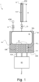
- FIG. 1 is a schematic diagram of a generator, generally designated by the numerical reference 1, according to one embodiment of the invention.
- This generator 1 notably comprises a vertical supply column 10 capable of being filled with a certain quantity of water so as to form a column of water 10A of a determined height H. It will be understood that the surface of the water column 10A is exposed to atmospheric pressure, designated ATM.
- This vertical supply column 10 is arranged above a sealed tank 30, itself filled with water, capable of being placed in communication with the vertical supply column 10 via an inlet valve 20 placed at the base of the vertical supply column 10, on the upper part 30A of the sealed tank 30.
- An exhaust valve 40 is also arranged on the sealed tank 30, which exhaust valve 40 is capable of releasing the pressure generated in the sealed tank 30 and allow the evacuation of excess water.
- This exhaust valve 40 here makes it possible to reduce the surface pressure of the liquid contained in the sealed tank 30 to atmospheric pressure ATM as well as the expulsion of excess water as will be understood on reading the description which follows.
- a piston device 50 Arranged inside the sealed tank 30 is a piston device 50 which is at least partially immersed in the water contained in the sealed tank 30.
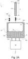
- This piston device 50 is capable of being set in reciprocating movement between a low position (see Figures 2B And 2C ) and a high position, as shown (see also Figures 2A And 2D ).
- the device forming a piston 50 comprises a first portion forming a float 51 capable of bringing the device forming a piston 50 into the high position and a second portion forming an output axis 52 emerging here in part, designated by the reference 52A, outside the sealed tank 30.
- the second portion forming an outlet axis 52 actually comprises a plurality of individual outlet axes 52, a part 52A of which emerges outside the sealed tank 30 , advantageously through a lower part 30B of the sealed tank 30.
- each outlet shaft 52 is provided with a compressible sleeve 55 ensuring sealing between the water contained in the sealed tank 30 and the part 52B of the outlet shaft 52 disposed inside the sealed tank 30.
- Each compressible cuff 55 defines a compressible volume, designated V 55 , devoid of liquid, encompassing the part 52B of the outlet axis 52 disposed inside the sealed reservoir 30.
- Other solutions could however be considered, for example example a solution adopting a single compressible cuff surrounding all of the output axes 52.
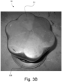
- FIGS. 3A And 3B are photographic illustrations of a prototype piston device 50, which consists of a set of seven individual output shafts 52 provided at their upper end with a flotation device, for example a block of polystyrene or any other material light and waterproof with good flotation capacity. All of the flotation devices are here arranged in the form of a compact whole and retained by an elastic sheath so as to constitute the float forming part 51 of the piston forming device 50. This part 51 moreover constitutes the head of the device forming piston 50.
- a flotation device for example a block of polystyrene or any other material light and waterproof with good flotation capacity. All of the flotation devices are here arranged in the form of a compact whole and retained by an elastic sheath so as to constitute the float forming part 51 of the piston forming device 50. This part 51 moreover constitutes the head of the device forming piston 50.
- the generator 1 further comprises a converter device 60 coupled here to the part 52A of the output axis 52 emerging outside the sealed tank 30.
- This converter device 60 can be any type of device capable of converting the reciprocating movement of the device forming a piston 50 into mechanical or electrical energy E.
- the converter device 60 can include a mechanism, as such known (such as a crankshaft type mechanism driven by connecting rods), capable of converting the reciprocating movement of the piston device 50 into a rotary movement.
- the converter device preferably comprises an alternator driven by the rotary movement in order to produce electrical energy.
- it may be a wind turbine alternator with permanent magnets, in particular permanent neodymium magnets. Tests were notably carried out by the Applicant using a Missouri Wind and Solar, LLC (www.mwands.com) brand alternator delivering approximately 12 Volts at 150 rpm.
- the vertical supply column 10 is dimensioned so as to allow the formation of a column of water 10A having a height H of the order of 50 cm to 150 cm.
- the internal diameter of the vertical supply column 10 is here preferably less than 20 cm.
- the sealed tank 30 has a capacity of around 20 to 50 liters.
- a water column of around 85 cm, an internal diameter of around 6 cm, and a sealed tank with a capacity of around 25 liters allow adequate implementation of the invention. It will be understood, however, that the invention is not specifically limited to these dimensions.
- Concerning the height H of the water column 10A this will depend in particular on the ceiling height available in the environment in which the generator according to the invention is installed.
- the generator is configured so that, in operation, the sealed tank 30 is filled with liquid, and so as to repeat the sequence of following operating phases described with reference to the Figures 2A to 2D in order to induce the reciprocating movement of the piston forming device 50.
- a first operational phase illustrated by the Figure 2A , the inlet valve 20 is closed (as is the exhaust valve 40) and the supply column 10 is filled with water so as to form a column of water 10A of determined height H. It will therefore be understood that a pressure is generated at the base of the water column 10A, the magnitude of which depends on the height H of the water column 10A.
- the inlet valve 20 is open (the exhaust valve 40 remaining closed) in order to put the vertical supply column 10 and the sealed tank 30 into communication, causing an increase in the pressure in the sealed tank 30 and causing a movement to the lower position of the device forming a piston 50.
- the increase in pressure in the sealed reservoir 30 causes the compression of the compressible cuffs 55 and a reduction in the compressible volume V 55 of each cuff 55, leading to an increase in the volume of water admitted into the sealed tank 30 and a corresponding reduction in the height, designated H*, of the column of water 10A in the vertical supply column 10.
- the cuffs 55 have in particular the advantage of offer little resistance to compression when the pressure increases in the sealed tank 30.
- a third operational phase illustrated by the Figure 2C , the inlet valve 20 is closed and the exhaust valve 40 is opened in order to release the excess pressure formed inside the sealed tank 30.
- This pressure balancing allows the piston device 50 to return to the high position under the action of the portion forming a float 51, part of the water contained in the sealed tank 30 being ejected via the exhaust valve 40 during this phase.
- the piston device 50 is thus returned to the high position under the action of the first float forming portion 51, and the process can then be repeated in order to induce an alternating movement of the piston device 50 between its high and low positions. It will be understood that additional water is added to the vertical supply column 10 in order to bring the water column 10A to the desired height H at the start of each cycle.
- the control of the inlet valve 20 and the exhaust valve 40 can be ensured by a mechanical distributor controlling the timing actuation of the valves 20, 40, it being understood that the valves 20, 40 are never opened simultaneously.
- the generator according to the invention operates at a relatively slow speed, similar to a steam engine, and it is preferable to equip this generator with a flywheel and a starter in order to ensure the initiation of operation. of the generator, the generator then being configured to maintain the rotation of the flywheel.
- the flywheel operates as an energy accumulator in mechanical form.
- the water supply to the generator 1 can in particular be ensured by means of a rainwater collection tank or a running water supply. It is also possible to use drain water delivered at the outlet of sanitary installations or any other suitable liquid.
- a certain quantity of water is “consumed” during each cycle of the generator 1.
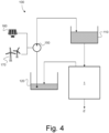
- an installation 100 as illustrated schematically in the Figure 4 comprising a collection tank 120 capable of recovering the water emanating from the sealed tank 30 of the generator 1 (in this case the water ejected via the exhaust valve 40) and returning this water into a supply tank 110 supplying the water necessary for filling the vertical supply column 10 of the generator 1.
- a pump 150 can be provided, preferably supplied with energy by means of photovoltaic panels 160 or by wind turbine 170, in order to return the water from the collection tank 120 to the supply tank 110.
- This pumping system operates in the manner of a pumped energy transfer station (or “STEP”) making it possible to exploit excess electrical energy produced by the photovoltaic panels 160 and/or the wind turbine 170 in order to pump the water collected in the collection tank 120 and return it to the supply tank 110.
- STEP pumped energy transfer station
- the pump 150 does not does not need to be operated continuously, but only periodically in order to return the collected water to the supply tank 110, therefore allowing closed circuit operation.
Landscapes
- Engineering & Computer Science (AREA)
- Mechanical Engineering (AREA)
- General Engineering & Computer Science (AREA)
- Chemical & Material Sciences (AREA)
- Combustion & Propulsion (AREA)
- Other Liquid Machine Or Engine Such As Wave Power Use (AREA)
Claims (15)
- Ein Generator (1), der aufweist:- eine vertikale Versorgungssäule (10), die geeignet ist, um mit einer bestimmten Menge an Flüssigkeit gefüllt zu werden;- ein Einlassventil (20), das an der Basis der vertikalen Versorgungssäule (10) angeordnet ist;- ein dichtes Reservoir (30) in Verbindung mit der vertikalen Versorgungssäule (10) über das Einlassventil (20), wobei das dichte Reservoir (30) geeignet ist, um mit Flüssigkeit gefüllt zu werden;- ein Auslassventil (40) das auf dem dichten Reservoir (30) angeordnet ist und geeignet ist, um den Druck abzulassen, der in dem dichten Reservoir (30) erzeugt wird;- eine Vorrichtung (50), die einen Kolben ausbildet, die innerhalb des dichten Reservoirs (30) so angeordnet ist, dass sie in die Flüssigkeit eingetaucht ist, die in dem dichten Reservoir (30) enthalten ist, wobei die Vorrichtung (50), die den Kolben ausbildet, geeignet ist, um in eine Hin- und Herbewegung zwischen einer oberen Position und einer unteren Position gebracht zu werden, wobei die Vorrichtung (50), die den Kolben ausbildet, einen ersten Abschnitt (51), der einen Schwimmer ausbildet, der geeignet ist, um die Vorrichtung (50), die den Kolben ausbildet, in die obere Position zu bringen, und einen zweiten Abschnitt aufweist, der eine Ausgangsachse (52) ausbildet; und- eine Wandlervorrichtung (60), die mit der Ausgangsachse (52) gekoppelt ist, wobei die Wandlervorrichtung (60) geeignet ist, um die Hin- und Herbewegung der Vorrichtung (50), die den Kolben ausbildet, in mechanische oder elektrische Energie umzuwandeln,wobei der Generator (1) so konfiguriert ist, dass, in Betrieb, das dichte Reservoir (30) mit Flüssigkeit gefüllt ist, und so, dass die Sequenz von folgenden Operationsphasen wiederholt wird, um die Hin- und Herbewegung der Vorrichtung (50), die den Kolben ausbildet, einzuleiten, nämlich:- eine erste Operationsphase, während der das Einlassventil (20) geschlossen ist und die vertikale Versorgungssäule (10) mit Flüssigkeit gefüllt ist, um eine Flüssigkeitssäule (10A) über dem dichten Reservoir (30) auszubilden;- eine zweite Operationsphase, während der das Auslassventil (40) geschlossen ist und das Einlassventil (20) geöffnet ist, um die vertikale Versorgungssäule (10) und das dichte Reservoir (30) in Verbindung zu setzen, wobei eine Erhöhung des Drucks in dem dichten Reservoir (30) erzeugt und eine Verschiebung in die untere Position der Vorrichtung (50), die den Kolben ausbildet, verursacht wird; und- eine dritte Operationsphase, während der das Einlassventil (20) geschlossen ist und das Auslassventil (40) geöffnet ist, um den überschüssigen Druck, der innerhalb des dichten Reservoirs (30) ausgebildet wird, abzulassen, wobei es der Vorrichtung (50), die den Kolben ausbildet, ermöglicht wird, unter der Einwirkung des ersten Abschnitts (51), der den Schwimmer ausbildet, in die obere Position zurückzukehren.
- Der Generator (1) nach Anspruch 1, wobei der zweite Abschnitt, der die Ausgangsachse (52) ausbildet, eine Vielzahl von individuellen Ausgangsachsen (52) aufweist,
und wobei jede individuelle Ausgangsachse (52) vorzugsweise mit einer Schwimmvorrichtung gekoppelt ist, die ihr eigen ist, wobei die Schwimmvorrichtungen miteinander gekoppelt sind, um den ersten Abschnitt (51), der den Schwimmer ausbildet, der Vorrichtung (50), die den Kolben ausbildet, zu bilden. - Der Generator (1) nach Anspruch 1 oder 2, wobei jede Ausgangsachse (52) mit einer komprimierbaren Manschette (55) vorgesehen ist, die eine Dichtheit zwischen der Flüssigkeit, die in dem dichten Reservoir (30) enthalten ist, und einem Teil (52B) der Ausgangsachse (52), der innerhalb des dichten Reservoirs (30) angeordnet ist, sicherstellt, wobei die komprimierbare Manschette (55) ein komprimierbares Volumen (V55) ohne Flüssigkeit definiert, das den Teil (52B) der Ausgangsachse (52) umgibt, der innerhalb des dichten Reservoirs (30) angeordnet ist.
- Der Generator (1) nach irgendeinem der vorstehenden Ansprüche, wobei der erste Abschnitt (51), der den Schwimmer ausbildet, auch einen Kopf der Vorrichtung (50), die den Kolben ausbildet, ausbildet.
- Der Generator (1) nach irgendeinem der vorstehenden Ansprüche, wobei die Ausgangsachse (52) zum Teil (52A) außerhalb des dichten Reservoirs (30) auftaucht,
und wobei die Wandlervorrichtung (60) mit dem Teil (52A) der Ausgangsachse (52), der außerhalb des dichten Reservoirs (30) auftaucht, gekoppelt ist. - Der Generator (1) nach Anspruch 5 in Abhängigkeit von Anspruch 3, wobei die komprimierbare Manschette (55) zwischen dem ersten Abschnitt (51), der den Schwimmer ausbildet, und einer Innenwand des dichten Reservoirs (30) eingesetzt ist.
- Der Generator (1) nach Anspruch 5 oder 6, wobei die Ausgangsachse (52) durch ein Bodenteil (30B) des dichten Reservoirs (30) hindurch auftaucht.
- Der Generator (1) nach irgendeinem der vorstehenden Ansprüche, wobei die Wandlervorrichtung (60) einen Mechanismus aufweist, der geeignet ist, um die Hin- und Herbewegung der Vorrichtung (50), die den Kolben ausbildet, in eine Drehbewegung umzuwandeln,
und wobei die Wandlervorrichtung (60) ferner vorzugsweise ein Wechselstromerzeuger ist, der durch die Drehbewegung angetrieben wird, um elektrische Energie zu produzieren. - Der Generator (1) nach irgendeinem der vorstehenden Ansprüche, der ferner eine automatische Steuervorrichtung zum Öffnen und zum Schließen des Einlass- und des Auslassventils (20, 40) aufweist, wie zum Beispiel einen mechanischen Verteiler.
- Der Generator (1) nach irgendeinem der vorstehenden Ansprüche, umfassend ferner einen Starter zum Initiieren der Drehung eines Schwungrads, das mit dem Generator (1) gekoppelt ist, wobei der Generator (1) konfiguriert ist, um das Versetzen des Schwungrads in Drehung zu erhalten.
- Der Generator (1) nach irgendeinem der vorstehenden Ansprüche, wobei die vertikale Versorgungssäule (10) zum Ermöglichen der Ausbildung einer Flüssigkeitssäule (1 0A) konfiguriert ist, die eine Höhe (H) in der Größenordnung von 50 cm bis 150 cm vorweist,
und wobei der Innendurchmesser der vertikalen Versorgungssäule (10) vorzugsweise kleiner als 20 cm ist. - Der Generator (1) nach irgendeinem der vorstehenden Ansprüche, wobei die Kapazität des dichten Reservoirs (30) in der Größenordnung von 20 bis 50 Liter ist.
- Eine Anlage (100), die einen Generator (1) nach irgendeinem der vorstehenden Ansprüche aufweist, der mit Flüssigkeit versorgt wird, wie zum Beispiel Wasser, insbesondere mittels eines Regenwassersammelreservoirs oder einer Fließwasserversorgung.
- Die Anlage (100) nach Anspruch 13, die ferner aufweist:ein Versorgungsreservoir (110), das geeignet ist, um die Flüssigkeit bereitzustellen, die für die Füllung der vertikalen Versorgungssäule (10) nötig ist;ein Sammelreservoir (120), das geeignet ist, um die Flüssigkeit abzufangen, die von dem dichten Reservoir (30) ausgeht; undeine Pumpe (150), die geeignet ist, um die Flüssigkeit des Sammelreservoirs (120) zu dem Versorgungsreservoir (110) zurückzubringen,wobei die Pumpe (150) vorzugsweise mittels Photovoltaikmodulen (160) oder durch eine Windkraftmaschine (170) mit Energie versorgt wird.
- Ein Verfahren zum Generieren von mechanischer oder elektrische Energie unter Verwendung des Generators (1) nach irgendeinem der Ansprüche 1 bis 12 oder der Anlage (100) nach dem Anspruch 13 oder 14, das die folgenden Schritte aufweist:a) Schließen des Einlassventils (20) und Füllen der vertikalen Versorgungssäule (10) mittels Flüssigkeit, um eine Flüssigkeitssäule (10A) über dem dichten Reservoir (30) auszubilden, das mit Flüssigkeit gefüllt ist;b) Schließen des Auslassventils (40) und Öffnen des Einlassventils (20), um die vertikale Versorgungssäule (10A) und das dichte Reservoir (30) in Verbindung zu setzen, wobei eine Erhöhung des Drucks in dem dichten Reservoir (30) erzeugt und eine Verschiebung in die untere Position der Vorrichtung (50), die den Kolben ausbildet, verursacht wird;c) Schließen des Einlassventils (20) und Öffnen des Auslassventils (40), um den überschüssigen Druck, der innerhalb des dichten Reservoirs (30) ausgebildet wird, abzulassen, wobei es der Vorrichtung (50), die den Kolben ausbildet, ermöglicht wird, unter der Einwirkung des ersten Abschnitts (51), der den Schwimmer ausbildet, in die obere Position zurückzukehren; undd) Wiederholen der Schritte a) bis d), um die Hin- und Herbewegung der Vorrichtung (50), die den Kolben ausbildet, einzuleiten, und es der Wandlervorrichtung (60) zu ermöglichen, diese Hin- und Herbewegung in mechanische oder elektrische Energie umzuwandeln.
Priority Applications (3)
| Application Number | Priority Date | Filing Date | Title |
|---|---|---|---|
| EP20209328.2A EP4001634B1 (de) | 2020-11-23 | 2020-11-23 | Flüssigkeitssäule-generator |
| CA3139219A CA3139219A1 (fr) | 2020-11-23 | 2021-11-16 | Generatrice a colonne de liquide |
| US17/532,477 US11603761B2 (en) | 2020-11-23 | 2021-11-22 | Liquid column generator |
Applications Claiming Priority (1)
| Application Number | Priority Date | Filing Date | Title |
|---|---|---|---|
| EP20209328.2A EP4001634B1 (de) | 2020-11-23 | 2020-11-23 | Flüssigkeitssäule-generator |
Publications (3)
| Publication Number | Publication Date |
|---|---|
| EP4001634A1 EP4001634A1 (de) | 2022-05-25 |
| EP4001634B1 true EP4001634B1 (de) | 2023-12-13 |
| EP4001634C0 EP4001634C0 (de) | 2023-12-13 |
Family
ID=73544107
Family Applications (1)
| Application Number | Title | Priority Date | Filing Date |
|---|---|---|---|
| EP20209328.2A Active EP4001634B1 (de) | 2020-11-23 | 2020-11-23 | Flüssigkeitssäule-generator |
Country Status (3)
| Country | Link |
|---|---|
| US (1) | US11603761B2 (de) |
| EP (1) | EP4001634B1 (de) |
| CA (1) | CA3139219A1 (de) |
Families Citing this family (1)
| Publication number | Priority date | Publication date | Assignee | Title |
|---|---|---|---|---|
| WO2025028669A1 (en) * | 2023-08-01 | 2025-02-06 | Mwongela Mwendwa | Engine that converts the potential energy of a liquid fluid stored in its upper tank to kinetic energy |
Family Cites Families (4)
| Publication number | Priority date | Publication date | Assignee | Title |
|---|---|---|---|---|
| US4267695A (en) * | 1979-09-27 | 1981-05-19 | Peter Micciche | Buoyancy energy engine |
| KR100389064B1 (ko) * | 2001-08-10 | 2003-06-25 | 김정기 | 부력과 중력을 이용한 발전시스템 |
| US20080289324A1 (en) * | 2007-05-24 | 2008-11-27 | Robert Marion | Clean energy generator |
| FI20185765A1 (fi) * | 2018-09-14 | 2020-03-15 | Lsk Granit Ky | Nestepumppu |
-
2020
- 2020-11-23 EP EP20209328.2A patent/EP4001634B1/de active Active
-
2021
- 2021-11-16 CA CA3139219A patent/CA3139219A1/fr active Pending
- 2021-11-22 US US17/532,477 patent/US11603761B2/en active Active
Also Published As
| Publication number | Publication date |
|---|---|
| US20220162942A1 (en) | 2022-05-26 |
| US11603761B2 (en) | 2023-03-14 |
| CA3139219A1 (fr) | 2022-05-23 |
| EP4001634C0 (de) | 2023-12-13 |
| EP4001634A1 (de) | 2022-05-25 |
Similar Documents
| Publication | Publication Date | Title |
|---|---|---|
| EP3303825B1 (de) | Vorrichtung und verfahren zur umwandlung und speicherung elektrischer energie in form von druckluft | |
| EP2140135B1 (de) | Vorrichtung und verfahren zur energieumwandlung aus einem strömenden fluid | |
| US7911073B2 (en) | System and method for a hydro-hydraulic gravitational generator | |
| BE1021499B1 (fr) | Centrale electrique thermique classique ou solaire thermodynamique a concentration | |
| WO2012160311A2 (fr) | Dispositif pour le stockage et la restitution de fluides et méthode pour stocker et restituer un gaz comprimé dans un tel dispositif | |
| GB2471538A (en) | Power generator using compressed air to turn an underwater generator | |
| US20020022165A1 (en) | Regenerative fuel cell system | |
| CN1826463B (zh) | 轻便水轮发电机 | |
| US20050079015A1 (en) | Hydropower generation apparatus and method | |
| EP4001634B1 (de) | Flüssigkeitssäule-generator | |
| FR3007804A1 (fr) | Dispositif hybride de production d'energie electrique | |
| EP2032841A1 (de) | Vorrichtung zur energieumwandlung | |
| EP3276159A1 (de) | Stromerzeugungsanlage | |
| FR2891095A1 (fr) | Installation de stockage et de recuperation d'energie electrique | |
| EP2392817A1 (de) | System zur erzeugung von strom durch die nutzung von wasserströmen | |
| US20250172117A1 (en) | Portable hydro-generator | |
| FR2983246A1 (fr) | Installation de stockage et de restitution d'energie sous forme de gaz comprime isobare et procede de stockage et de restitution d'energie correspondant | |
| WO2016028133A1 (fr) | Générateur électrique écologique | |
| FR3097593A1 (fr) | Dispositif hybride de stockage ou de conversion énergétiques, à fluide propulseur liquide, gazeux ou supercritique | |
| FR2757904A1 (fr) | Convertisseur d'energie d'hydrodynamique asymetrique | |
| FR2973841A1 (fr) | Installation de conversion d'energie thermique en energie electrique | |
| WO2010093267A2 (fr) | Systeme et methode de production autonome de fluide et d'electricite | |
| FR3149050A1 (fr) | Systeme de production d’electricite par gravite | |
| JP2001295747A (ja) | 水面下マンホール水力発電システム | |
| JP2000110702A (ja) | 連続循環式水力発電装置及び方法並びに該装置に用いる水面加圧式タンク |
Legal Events
| Date | Code | Title | Description |
|---|---|---|---|
| PUAI | Public reference made under article 153(3) epc to a published international application that has entered the european phase |
Free format text: ORIGINAL CODE: 0009012 |
|
| STAA | Information on the status of an ep patent application or granted ep patent |
Free format text: STATUS: THE APPLICATION HAS BEEN PUBLISHED |
|
| AK | Designated contracting states |
Kind code of ref document: A1 Designated state(s): AL AT BE BG CH CY CZ DE DK EE ES FI FR GB GR HR HU IE IS IT LI LT LU LV MC MK MT NL NO PL PT RO RS SE SI SK SM TR |
|
| STAA | Information on the status of an ep patent application or granted ep patent |
Free format text: STATUS: REQUEST FOR EXAMINATION WAS MADE |
|
| 17P | Request for examination filed |
Effective date: 20221115 |
|
| RBV | Designated contracting states (corrected) |
Designated state(s): AL AT BE BG CH CY CZ DE DK EE ES FI FR GB GR HR HU IE IS IT LI LT LU LV MC MK MT NL NO PL PT RO RS SE SI SK SM TR |
|
| GRAP | Despatch of communication of intention to grant a patent |
Free format text: ORIGINAL CODE: EPIDOSNIGR1 |
|
| STAA | Information on the status of an ep patent application or granted ep patent |
Free format text: STATUS: GRANT OF PATENT IS INTENDED |
|
| INTG | Intention to grant announced |
Effective date: 20230112 |
|
| GRAJ | Information related to disapproval of communication of intention to grant by the applicant or resumption of examination proceedings by the epo deleted |
Free format text: ORIGINAL CODE: EPIDOSDIGR1 |
|
| STAA | Information on the status of an ep patent application or granted ep patent |
Free format text: STATUS: REQUEST FOR EXAMINATION WAS MADE |
|
| GRAP | Despatch of communication of intention to grant a patent |
Free format text: ORIGINAL CODE: EPIDOSNIGR1 |
|
| STAA | Information on the status of an ep patent application or granted ep patent |
Free format text: STATUS: GRANT OF PATENT IS INTENDED |
|
| INTC | Intention to grant announced (deleted) | ||
| INTG | Intention to grant announced |
Effective date: 20230627 |
|
| GRAS | Grant fee paid |
Free format text: ORIGINAL CODE: EPIDOSNIGR3 |
|
| GRAA | (expected) grant |
Free format text: ORIGINAL CODE: 0009210 |
|
| STAA | Information on the status of an ep patent application or granted ep patent |
Free format text: STATUS: THE PATENT HAS BEEN GRANTED |
|
| AK | Designated contracting states |
Kind code of ref document: B1 Designated state(s): AL AT BE BG CH CY CZ DE DK EE ES FI FR GB GR HR HU IE IS IT LI LT LU LV MC MK MT NL NO PL PT RO RS SE SI SK SM TR |
|
| REG | Reference to a national code |
Ref country code: GB Ref legal event code: FG4D Free format text: NOT ENGLISH |
|
| REG | Reference to a national code |
Ref country code: CH Ref legal event code: EP |
|
| REG | Reference to a national code |
Ref country code: DE Ref legal event code: R096 Ref document number: 602020022628 Country of ref document: DE |
|
| REG | Reference to a national code |
Ref country code: IE Ref legal event code: FG4D Free format text: LANGUAGE OF EP DOCUMENT: FRENCH |
|
| REG | Reference to a national code |
Ref country code: CH Ref legal event code: PK Free format text: RECTIFICATIONS |
|
| U01 | Request for unitary effect filed |
Effective date: 20240105 |
|
| U07 | Unitary effect registered |
Designated state(s): AT BE BG DE DK EE FI FR IT LT LU LV MT NL PT SE SI Effective date: 20240117 |
|
| PG25 | Lapsed in a contracting state [announced via postgrant information from national office to epo] |
Ref country code: GR Free format text: LAPSE BECAUSE OF FAILURE TO SUBMIT A TRANSLATION OF THE DESCRIPTION OR TO PAY THE FEE WITHIN THE PRESCRIBED TIME-LIMIT Effective date: 20240314 |
|
| PG25 | Lapsed in a contracting state [announced via postgrant information from national office to epo] |
Ref country code: ES Free format text: LAPSE BECAUSE OF FAILURE TO SUBMIT A TRANSLATION OF THE DESCRIPTION OR TO PAY THE FEE WITHIN THE PRESCRIBED TIME-LIMIT Effective date: 20231213 |
|
| PG25 | Lapsed in a contracting state [announced via postgrant information from national office to epo] |
Ref country code: GR Free format text: LAPSE BECAUSE OF FAILURE TO SUBMIT A TRANSLATION OF THE DESCRIPTION OR TO PAY THE FEE WITHIN THE PRESCRIBED TIME-LIMIT Effective date: 20240314 Ref country code: ES Free format text: LAPSE BECAUSE OF FAILURE TO SUBMIT A TRANSLATION OF THE DESCRIPTION OR TO PAY THE FEE WITHIN THE PRESCRIBED TIME-LIMIT Effective date: 20231213 |
|
| PG25 | Lapsed in a contracting state [announced via postgrant information from national office to epo] |
Ref country code: RS Free format text: LAPSE BECAUSE OF FAILURE TO SUBMIT A TRANSLATION OF THE DESCRIPTION OR TO PAY THE FEE WITHIN THE PRESCRIBED TIME-LIMIT Effective date: 20231213 Ref country code: NO Free format text: LAPSE BECAUSE OF FAILURE TO SUBMIT A TRANSLATION OF THE DESCRIPTION OR TO PAY THE FEE WITHIN THE PRESCRIBED TIME-LIMIT Effective date: 20240313 Ref country code: HR Free format text: LAPSE BECAUSE OF FAILURE TO SUBMIT A TRANSLATION OF THE DESCRIPTION OR TO PAY THE FEE WITHIN THE PRESCRIBED TIME-LIMIT Effective date: 20231213 |
|
| PG25 | Lapsed in a contracting state [announced via postgrant information from national office to epo] |
Ref country code: IS Free format text: LAPSE BECAUSE OF FAILURE TO SUBMIT A TRANSLATION OF THE DESCRIPTION OR TO PAY THE FEE WITHIN THE PRESCRIBED TIME-LIMIT Effective date: 20240413 |
|
| PG25 | Lapsed in a contracting state [announced via postgrant information from national office to epo] |
Ref country code: CZ Free format text: LAPSE BECAUSE OF FAILURE TO SUBMIT A TRANSLATION OF THE DESCRIPTION OR TO PAY THE FEE WITHIN THE PRESCRIBED TIME-LIMIT Effective date: 20231213 |
|
| PG25 | Lapsed in a contracting state [announced via postgrant information from national office to epo] |
Ref country code: SK Free format text: LAPSE BECAUSE OF FAILURE TO SUBMIT A TRANSLATION OF THE DESCRIPTION OR TO PAY THE FEE WITHIN THE PRESCRIBED TIME-LIMIT Effective date: 20231213 |
|
| PG25 | Lapsed in a contracting state [announced via postgrant information from national office to epo] |
Ref country code: SM Free format text: LAPSE BECAUSE OF FAILURE TO SUBMIT A TRANSLATION OF THE DESCRIPTION OR TO PAY THE FEE WITHIN THE PRESCRIBED TIME-LIMIT Effective date: 20231213 Ref country code: SK Free format text: LAPSE BECAUSE OF FAILURE TO SUBMIT A TRANSLATION OF THE DESCRIPTION OR TO PAY THE FEE WITHIN THE PRESCRIBED TIME-LIMIT Effective date: 20231213 Ref country code: RO Free format text: LAPSE BECAUSE OF FAILURE TO SUBMIT A TRANSLATION OF THE DESCRIPTION OR TO PAY THE FEE WITHIN THE PRESCRIBED TIME-LIMIT Effective date: 20231213 Ref country code: IS Free format text: LAPSE BECAUSE OF FAILURE TO SUBMIT A TRANSLATION OF THE DESCRIPTION OR TO PAY THE FEE WITHIN THE PRESCRIBED TIME-LIMIT Effective date: 20240413 Ref country code: CZ Free format text: LAPSE BECAUSE OF FAILURE TO SUBMIT A TRANSLATION OF THE DESCRIPTION OR TO PAY THE FEE WITHIN THE PRESCRIBED TIME-LIMIT Effective date: 20231213 |
|
| PG25 | Lapsed in a contracting state [announced via postgrant information from national office to epo] |
Ref country code: PL Free format text: LAPSE BECAUSE OF FAILURE TO SUBMIT A TRANSLATION OF THE DESCRIPTION OR TO PAY THE FEE WITHIN THE PRESCRIBED TIME-LIMIT Effective date: 20231213 |
|
| PG25 | Lapsed in a contracting state [announced via postgrant information from national office to epo] |
Ref country code: PL Free format text: LAPSE BECAUSE OF FAILURE TO SUBMIT A TRANSLATION OF THE DESCRIPTION OR TO PAY THE FEE WITHIN THE PRESCRIBED TIME-LIMIT Effective date: 20231213 |
|
| REG | Reference to a national code |
Ref country code: DE Ref legal event code: R097 Ref document number: 602020022628 Country of ref document: DE |
|
| PLBE | No opposition filed within time limit |
Free format text: ORIGINAL CODE: 0009261 |
|
| STAA | Information on the status of an ep patent application or granted ep patent |
Free format text: STATUS: NO OPPOSITION FILED WITHIN TIME LIMIT |
|
| 26N | No opposition filed |
Effective date: 20240916 |
|
| U20 | Renewal fee for the european patent with unitary effect paid |
Year of fee payment: 5 Effective date: 20241129 |
|
| PG25 | Lapsed in a contracting state [announced via postgrant information from national office to epo] |
Ref country code: MC Free format text: LAPSE BECAUSE OF FAILURE TO SUBMIT A TRANSLATION OF THE DESCRIPTION OR TO PAY THE FEE WITHIN THE PRESCRIBED TIME-LIMIT Effective date: 20231213 |
|
| PG25 | Lapsed in a contracting state [announced via postgrant information from national office to epo] |
Ref country code: IE Free format text: LAPSE BECAUSE OF NON-PAYMENT OF DUE FEES Effective date: 20241123 |
|
| REG | Reference to a national code |
Ref country code: CH Ref legal event code: U11 Free format text: ST27 STATUS EVENT CODE: U-0-0-U10-U11 (AS PROVIDED BY THE NATIONAL OFFICE) Effective date: 20251204 |
|
| U20 | Renewal fee for the european patent with unitary effect paid |
Year of fee payment: 6 Effective date: 20251112 |
|
| PGFP | Annual fee paid to national office [announced via postgrant information from national office to epo] |
Ref country code: GB Payment date: 20251121 Year of fee payment: 6 |
|
| PGFP | Annual fee paid to national office [announced via postgrant information from national office to epo] |
Ref country code: CH Payment date: 20251204 Year of fee payment: 6 |
|
| PG25 | Lapsed in a contracting state [announced via postgrant information from national office to epo] |
Ref country code: HU Free format text: LAPSE BECAUSE OF FAILURE TO SUBMIT A TRANSLATION OF THE DESCRIPTION OR TO PAY THE FEE WITHIN THE PRESCRIBED TIME-LIMIT; INVALID AB INITIO Effective date: 20201123 |
|
| PG25 | Lapsed in a contracting state [announced via postgrant information from national office to epo] |
Ref country code: CY Free format text: LAPSE BECAUSE OF FAILURE TO SUBMIT A TRANSLATION OF THE DESCRIPTION OR TO PAY THE FEE WITHIN THE PRESCRIBED TIME-LIMIT; INVALID AB INITIO Effective date: 20201123 |