EP3303825B1 - Vorrichtung und verfahren zur umwandlung und speicherung elektrischer energie in form von druckluft - Google Patents
Vorrichtung und verfahren zur umwandlung und speicherung elektrischer energie in form von druckluft Download PDFInfo
- Publication number
- EP3303825B1 EP3303825B1 EP16729814.0A EP16729814A EP3303825B1 EP 3303825 B1 EP3303825 B1 EP 3303825B1 EP 16729814 A EP16729814 A EP 16729814A EP 3303825 B1 EP3303825 B1 EP 3303825B1
- Authority
- EP
- European Patent Office
- Prior art keywords
- dynamo
- conversion
- liquid
- hydraulic
- pressure
- Prior art date
- Legal status (The legal status is an assumption and is not a legal conclusion. Google has not performed a legal analysis and makes no representation as to the accuracy of the status listed.)
- Active
Links
Images


Classifications
-
- F—MECHANICAL ENGINEERING; LIGHTING; HEATING; WEAPONS; BLASTING
- F03—MACHINES OR ENGINES FOR LIQUIDS; WIND, SPRING, OR WEIGHT MOTORS; PRODUCING MECHANICAL POWER OR A REACTIVE PROPULSIVE THRUST, NOT OTHERWISE PROVIDED FOR
- F03B—MACHINES OR ENGINES FOR LIQUIDS
- F03B13/00—Adaptations of machines or engines for special use; Combinations of machines or engines with driving or driven apparatus; Power stations or aggregates
- F03B13/06—Stations or aggregates of water-storage type, e.g. comprising a turbine and a pump
-
- F—MECHANICAL ENGINEERING; LIGHTING; HEATING; WEAPONS; BLASTING
- F03—MACHINES OR ENGINES FOR LIQUIDS; WIND, SPRING, OR WEIGHT MOTORS; PRODUCING MECHANICAL POWER OR A REACTIVE PROPULSIVE THRUST, NOT OTHERWISE PROVIDED FOR
- F03B—MACHINES OR ENGINES FOR LIQUIDS
- F03B3/00—Machines or engines of reaction type; Parts or details peculiar thereto
- F03B3/10—Machines or engines of reaction type; Parts or details peculiar thereto characterised by having means for functioning alternatively as pumps or turbines
-
- H—ELECTRICITY
- H02—GENERATION; CONVERSION OR DISTRIBUTION OF ELECTRIC POWER
- H02K—DYNAMO-ELECTRIC MACHINES
- H02K7/00—Arrangements for handling mechanical energy structurally associated with dynamo-electric machines, e.g. structural association with mechanical driving motors or auxiliary dynamo-electric machines
- H02K7/18—Structural association of electric generators with mechanical driving motors, e.g. with turbines
- H02K7/1807—Rotary generators
- H02K7/1823—Rotary generators structurally associated with turbines or similar engines
-
- E—FIXED CONSTRUCTIONS
- E02—HYDRAULIC ENGINEERING; FOUNDATIONS; SOIL SHIFTING
- E02B—HYDRAULIC ENGINEERING
- E02B9/00—Water-power plants; Layout, construction or equipment, methods of, or apparatus for, making same
- E02B9/02—Water-ways
- E02B9/06—Pressure galleries or pressure conduits; Galleries specially adapted to house pressure conduits; Means specially adapted for use therewith, e.g. housings, valves, gates
-
- F—MECHANICAL ENGINEERING; LIGHTING; HEATING; WEAPONS; BLASTING
- F05—INDEXING SCHEMES RELATING TO ENGINES OR PUMPS IN VARIOUS SUBCLASSES OF CLASSES F01-F04
- F05B—INDEXING SCHEME RELATING TO WIND, SPRING, WEIGHT, INERTIA OR LIKE MOTORS, TO MACHINES OR ENGINES FOR LIQUIDS COVERED BY SUBCLASSES F03B, F03D AND F03G
- F05B2220/00—Application
- F05B2220/30—Application in turbines
- F05B2220/32—Application in turbines in water turbines
-
- F—MECHANICAL ENGINEERING; LIGHTING; HEATING; WEAPONS; BLASTING
- F05—INDEXING SCHEMES RELATING TO ENGINES OR PUMPS IN VARIOUS SUBCLASSES OF CLASSES F01-F04
- F05B—INDEXING SCHEME RELATING TO WIND, SPRING, WEIGHT, INERTIA OR LIKE MOTORS, TO MACHINES OR ENGINES FOR LIQUIDS COVERED BY SUBCLASSES F03B, F03D AND F03G
- F05B2240/00—Components
- F05B2240/40—Use of a multiplicity of similar components
-
- F—MECHANICAL ENGINEERING; LIGHTING; HEATING; WEAPONS; BLASTING
- F05—INDEXING SCHEMES RELATING TO ENGINES OR PUMPS IN VARIOUS SUBCLASSES OF CLASSES F01-F04
- F05B—INDEXING SCHEME RELATING TO WIND, SPRING, WEIGHT, INERTIA OR LIKE MOTORS, TO MACHINES OR ENGINES FOR LIQUIDS COVERED BY SUBCLASSES F03B, F03D AND F03G
- F05B2240/00—Components
- F05B2240/90—Mounting on supporting structures or systems
- F05B2240/95—Mounting on supporting structures or systems offshore
-
- F—MECHANICAL ENGINEERING; LIGHTING; HEATING; WEAPONS; BLASTING
- F05—INDEXING SCHEMES RELATING TO ENGINES OR PUMPS IN VARIOUS SUBCLASSES OF CLASSES F01-F04
- F05B—INDEXING SCHEME RELATING TO WIND, SPRING, WEIGHT, INERTIA OR LIKE MOTORS, TO MACHINES OR ENGINES FOR LIQUIDS COVERED BY SUBCLASSES F03B, F03D AND F03G
- F05B2260/00—Function
- F05B2260/42—Storage of energy
-
- Y—GENERAL TAGGING OF NEW TECHNOLOGICAL DEVELOPMENTS; GENERAL TAGGING OF CROSS-SECTIONAL TECHNOLOGIES SPANNING OVER SEVERAL SECTIONS OF THE IPC; TECHNICAL SUBJECTS COVERED BY FORMER USPC CROSS-REFERENCE ART COLLECTIONS [XRACs] AND DIGESTS
- Y02—TECHNOLOGIES OR APPLICATIONS FOR MITIGATION OR ADAPTATION AGAINST CLIMATE CHANGE
- Y02E—REDUCTION OF GREENHOUSE GAS [GHG] EMISSIONS, RELATED TO ENERGY GENERATION, TRANSMISSION OR DISTRIBUTION
- Y02E10/00—Energy generation through renewable energy sources
- Y02E10/20—Hydro energy
-
- Y—GENERAL TAGGING OF NEW TECHNOLOGICAL DEVELOPMENTS; GENERAL TAGGING OF CROSS-SECTIONAL TECHNOLOGIES SPANNING OVER SEVERAL SECTIONS OF THE IPC; TECHNICAL SUBJECTS COVERED BY FORMER USPC CROSS-REFERENCE ART COLLECTIONS [XRACs] AND DIGESTS
- Y02—TECHNOLOGIES OR APPLICATIONS FOR MITIGATION OR ADAPTATION AGAINST CLIMATE CHANGE
- Y02E—REDUCTION OF GREENHOUSE GAS [GHG] EMISSIONS, RELATED TO ENERGY GENERATION, TRANSMISSION OR DISTRIBUTION
- Y02E60/00—Enabling technologies; Technologies with a potential or indirect contribution to GHG emissions mitigation
- Y02E60/16—Mechanical energy storage, e.g. flywheels or pressurised fluids
Definitions
- the present invention relates to a device for converting energy of electrical origin and energy storage in the form of compressed air using a liquid medium, in particular the aquatic medium.
- the present invention also relates to a conversion process between the forms of electrical energy and respectively aeraulic.
- Such a device makes it possible to easily and efficiently convert electrical energy into storage a Vogellic energy and vice versa to be distributed on the network.
- the invention is particularly applicable to the field of conversion of electrical energy and storage thereof once converted into a form capable of durable accumulation, in this case the form of compressed air.
- the trapped air is compressed to a predetermined pressure by pumping liquid into the conversion chamber, the liquid forming a liquid compression piston.
- the compressed air is then transferred to the compressed air storage tank. Then the liquid is replaced by low pressure air in the conversion chamber is a new conversion cycle can begin.
- the energy stored as compressed air is reconverted into electricity.
- the compressed air of the storage tank is transferred into the conversion chamber initially filled with liquid.
- the compressed air expands in the conversion chamber and delivers the liquid through a dynamo-hydraulic machine, such as a turbine, coupled to an electric generator supplying the network.
- the problem is complicated by the necessity that the conversion of electrical energy in another form or conversely is accomplished from an electrical point of view with power as little fluctuating as possible in order to facilitate the absorption or the restitution of the energy. on the network.
- the object of the present invention is to overcome all or part of at least one of the aforementioned problems with a new device for converting electrical energy into pneumatic energy and vice versa.
- An object of the invention is to provide a device with a good cost-effectiveness.
- the invention also aims to limit energy losses.
- the invention also aims to provide a device providing electrical energy so that the power fluctuation due to the conversion mode is low.
- Yet another object of the invention is to provide a machine comprising a reduced number of parts and / or components.
- At least one dynamo-hydraulic machine is provided to operate in a narrow pressure range substantially corresponding to the pressure of the storage tank. Since part of the pumping and part of the hydraulic expansion is done at substantially stabilized pressure during transfers between the tank and the conversion chamber, it is advantageous for at least one dynamo-hydraulic machine to be calibrated for this pressure. .
- the dynamo-hydraulic machines are mounted hydraulically in parallel with each other between a source of low pressure liquid and the at least one conversion chamber.
- the storage tank is preferably underwater and open at the bottom to receive water from the aquatic environment enclosing a pocket of air at a pressure defined by the depth of immersion of the tank.
- a reservoir can be made in a simple and reliable way that can have a very large capacity subjected to a stable pressure which can be without moving parts or deformable walls. This is the level of water in the tank that serves as a deformable wall adjusting according to the amount of compressed air stored.
- the device comprises at least two conversion chambers in order to permanently maintain the energy flow in the dynamo-hydraulic machines.
- a conversion chamber is in the resetting phase (draining water for a new compression cycle or filling the water for a new expansion cycle), the other can continue to be energetically active.
- the cycles of variation of liquid level in the conversion chambers are out of phase between conversion chambers, each dynamo-hydraulic machine being successively connected to several conversion chambers being staggered in time in the pressure range corresponding to this dynamo-hydraulic machine. It can thus be ensured that the dynamo-hydraulic machines operate almost permanently or permanently in succession with the different conversion chambers.
- a pause is provided at the moment when the at least one conversion chamber passes from one dynamo-hydraulic machine to another.
- Hydraulic readjustment means in particular low pressure pumps, may be provided for readjusting the liquid level to its initial state in order to carry out pumping or turbining in the at least one conversion chamber.
- the device comprises more conversion chambers than dynamo-hydraulic machines.
- the conversion chambers which are not connected to any dynamo-hydraulic machine may be in the resetting phase, or in the pause phase between two stages of compression or expansion.
- the dynamo-hydraulic machines are of the pump-turbine type adapted to operate in pump or vice versa turbine. They are even more preferably of the Kaplan or Dériaz type.
- the dynamo-electric machines are reversible generating engines, operating in motors for the storage of aeraulic energy in the tank and in a generator for the production of electricity during aerodynamic destocking.
- the bidirectional communication means are closed except during a final phase of the compression and during an initial phase of the expansion.
- the compressed air inlet coming from the storage tank is closed, and the pressure is reduced.
- the compressed air present in the conversion chamber while the remaining liquid is discharged to be turbined. It is thus possible to relax as completely as desired each elementary quantity of compressed air admitted into the conversion chamber at each cycle, and this with excellent energy efficiency thanks to the stepped expansion according to the invention.
- the compression of the air and / or the expansion of the air in the at least one conversion chamber is quasi-isothermal.
- thermal conductors are placed vertically in the conversion chambers to transfer the calories generated in the air by compression to the water, and to transfer calories taken from the water to the air. of relaxation.
- These conductors may be a bundle of vertical tubes open at both ends and extending over substantially the entire height of the conversion chamber.
- the device may include super-capacitors to regulate the power that the device exchanges with the network.
- variants of the invention comprising only a selection of characteristics described below, isolated from the other characteristics described (even if this selection is isolated within a sentence including these other characteristics), if this selection of characteristics is sufficient to confer a technical advantage or to differentiate the invention from the state of the art.
- This selection comprises at least one preferably functional characteristic without structural details, and / or with only a part of the structural details if this part alone is sufficient to confer a technical advantage or to differentiate the invention from the state of the art. earlier.
- One of the preferred embodiments is a device for converting and storing electrical energy at sea. Its purpose is to absorb the electrical surpluses to convert and store them in the form of aeraulic energy, then when the network becomes applicant reconvert the aeraulic energy into electrical energy to restore it to the network. Between these two active phases, energy is stored as compressed air in at least one underwater storage tank, typically submarine, at a storage pressure.
- the underwater storage tank 20 is open at the bottom to communicate with the aquatic environment and enclose in the upper part, above the water level in the tank, a pocket of compressed air at a desired pressure defined by the immersion depth of the tank.
- the reservoir consists of several contiguous and integral cells.
- the tank is placed on the bottom of the body of water, typically the seabed.
- a typical immersion depth is between 70 and 200 m, preferably of the order of 100 m.
- the energy conversion device is placed on a floating platform 10.
- the floating platform includes the electromechanical, hydromechanical and hydropneumatic conversion systems as well as the associated electrical and electronic systems to enable the conversion of electrical energy into pneumatic energy. we also call aeraulic) and vice versa.
- a synoptic of the principal of these equipments is represented in figure 2 .
- the platform is connected to the electricity grid by High-voltage underwater electrical cable 18. Maintaining the position of the above-ground platform above the compressed air storage tanks 20 is achieved by means of a set of permanent anchor lines 19 .
- the energy conversion device comprises dynamo-electric machines MG1, MG2, MG3 designed to operate as a motor that absorbs the electrical energy to be converted from the network installation and transforms it into mechanical energy and / or to operate as a generator. using mechanical energy produced from the aeraulic energy stored in the reservoir 20 to convert this mechanical energy stored electrical energy to restore the network.
- the dynamo-electric machines MG1, MG2, MG3 are reversible generating motors.
- the scheme of the figure 2 is broken down into two parts: a framed part of fine dotted lines which corresponds to a purely hydraulic part and a framed part of broken lines which corresponds to a purely aeraulic part.
- the device comprises dynamo-hydraulic machines PT1, PT2 and PT3 for respectively pumping or turbining water.
- the dynamo-hydraulic machines PT1, PT2 and PT3 are reversible machines capable of operating either as pumps, in particular turbopumps, or as expansion machines, in particular turbines. But the invention is applicable by using specific machines for pumping and for relaxing, respectively.
- each dynamo-hydraulic machine PT1, PT2, PT3 is coupled to the shaft of a respective dynamo-electric machine MG1, MG2, MG3, as represented by the references 21.
- the dynamo-hydraulic machines operating in pumping convert the mechanical energy from dynamo-electric machines operating in motor, hydraulic energy by pumping a liquid drawn from a source such as the water of the surrounding aquatic environment and repressing the liquid to an increased pressure by pumping in a discharge port 16.
- Dynamo-hydraulic machines operating in a hydraulic expansion machine, in particular turbining can convert the hydraulic energy into mechanical energy supplied to the shaft of the dynamo-electric machine operating as a generator, by the turbining of the liquid arriving under a certain pressure at the high pressure port 16 and leaving the dynamo-hydraulic machine through its low pressure port 14 to return to the tank, particularly the surrounding aquatic environment.
- the dynamo-hydraulic machines can be pump-turbines of the Kaplan or Dériaz type. These pump-turbines make it possible to vary their flow rate at a constant speed, which makes it possible in particular to tend towards a uniformization of the power despite the variation of the pressure during compression of the air, and thus to limit the variation of electric power seen by the electric machines.
- the device comprises conversion chambers CH1, CH2, CH3, CH4, CH5, CH6 each having a lower orifice adapted to be connected to the high pressure port 16 of the dynamo-hydraulic machines PT1, PT2, PT3 by a valve system of distribution 17, an upper orifice adapted to be connected by a valve 11 to the bi-directional communication pipe 13 with the reservoir 20, and an upper orifice adapted to be connected to the open air by a valve 12 and a filling-emptying pipe 22.
- each conversion chamber contains air at the top and working liquid, typically water from the aquatic environment, at the bottom. The water present in the chamber at the bottom part forms a liquid piston for compressing or relaxing the air.
- the conversion chamber makes it possible to convert hydraulic energy into pneumatic energy and vice versa.
- the device comprises more conversion chambers than PT1, PT2, PT3 dynamohydraulic machines capable of operating as a pump and more conversion chambers than PT1, PT2, PT3 dynamo-hydraulic machines capable of operating in mechanical machines. hydraulic relaxation.
- This feature helps maintain in operation all the dynamo-hydraulic machines operating according to the case in pumps or turbines even during the filling or emptying of at least one conversion chamber.
- the device further comprises hydraulic readjustment means P1, P2, P3 to readjust the liquid level to its initial state to perform the pumping or turbining in the conversion chambers. They take the liquid at the same source as the dynamo-hydraulic machines PT1, PT2, PT3, in the example the surrounding aquatic environment, and return the liquid to said source.
- the readjustment means are pumps (P1, P2 and P3) which operate at low pressure difference, just sufficient to balance the pressure losses and the possible hydrostatic pressure differential resulting from the height of water in the pumps. conversion chambers relative to the source level.
- the readjustment means are bidirectional pumps also capable of emptying or accelerating the emptying of the conversion chambers when they must be filled with air prior to a compression cycle.
- the distribution means 17 are designed to also ensure the selective connection of each CH1-CH6 conversion chamber with a readjustment pump P1, P2 or P3.
- the dynamo-hydraulic means for pumping and hydraulic expansion comprise machines PT1, PT2, PT3 which differ from each other by their respective pressure range measured in operation at their high pressure port 16, and which also differ. by their maximum flow.
- the figure 3 comprises three windows 3a, 3b, 3c respectively presenting the characteristic steps of the storage phase for a conversion chamber.
- the windows 3a and 3b correspond to the productive steps and the window 3c corresponds to a non-productive step, which could be called a resetting step.
- the conversion chamber CH1 is full of air at atmospheric pressure, the water is at a minimum level.
- the two-way communication and venting valves 12 are closed so that the upper part of the conversion chamber, occupied by the air, is hermetically closed.
- the electrical energy to be stored supplies the dynamo-electric machine MG1 coupled to the dynamo-hydraulic machine PT1 which pumps water into the conversion chamber CH1 under moderate pressure.
- the distribution means 17 interrupt the connection of the conversion chamber CH1 with the machine dynamo-hydraulic PT1 and establish the connection of the conversion chamber with the high pressure port 16 of the dynamo-hydraulic machine PT2 coupled to the dynamo-electric machine MG2.
- the electrical energy to be stored supplies the dynamo-electric machine MG2 coupled to the dynamo-hydraulic machine PT2 which pumps the water into the conversion chamber CH1 under increased pressure.
- the distribution means 17 interrupt the connection of the conversion chamber CH1 with the dynamo-hydraulic machine PT2 and establish the connection of the conversion chamber with the high pressure port 16 of the dynamo-hydraulic machine PT3 coupled to the dynamo-electric machine MG3.
- the valve 11 opens window 3b of the figure 3 ).
- the electrical energy to be stored powers the dynamo-electric machine MG3 coupled to the dynamo-hydraulic machine PT3 which pumps the water into the conversion chamber CH1 under the pressure of the storage tank 20 until substantially all the air The tablet present in the conversion chamber CH1 has been discharged into the tank 20.
- the liquid typically the water of the aquatic medium
- the liquid is pumped to form a liquid piston in the conversion chamber in which a quantity of air is trapped.
- the water / air interface moves from bottom to top of the conversion chamber forming a piston compressing the air trapped in the conversion chamber until the air reaches the pressure in the storage tank.
- the liquid piston has the advantage of limiting the energy losses due to friction compared to a conventional rigid piston compressor.
- the use of the liquid piston makes it possible to limit heat losses, that is to say to limit heating due to compression, which is therefore quasi-isothermal.
- the conversion chambers preferably contain thermal conductors which thermally connect the air and the liquid in the conversion chambers. These thermal conductors are for example a bundle of vertical metal tubes, open at both ends, extending over substantially the entire height of each chamber. These conductors release the compression heat of the air in the compression cycle into the water, which reduces the work required for compression, and warms the air with heat from the water in the expansion cycle. which increases the work provided by the relaxation of the air.
- the dynamo-hydraulic machine PT1 operates in the low pressure range ( atmospheric pressure up to 0.3 or 0.4 MPa)
- the dynamo-hydraulic machine PT2 operates in the intermediate pressure range (from 0.3 to 0.4 MPa up to 1.1 MPa)
- the dynamo machine - Hydraulic PT3 works in a narrow range around 1.1 MPa.
- the conversion device carries out several pumping cycles, each cycle passing through the successive pressure ranges.
- the duration of a cycle is scheduled between 30 seconds and 5 minutes.
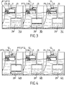
- the figure 4 comprises three windows 4a, 4b, 4c respectively presenting the characteristic steps of the destocking phase for a conversion chamber CH1.
- the windows 4a and 4b correspond to the productive steps and the window 4c corresponds to a non-productive or reset stage.
- the conversion chamber is full of water.
- the venting means 12 are closed.
- the bidirectional communication valve 11 is opened so that the compressed air present in the storage tank 20 is partly transferred to the conversion chamber CH1 and displaces part of the water contained in the conversion chamber through the high-pressure PT3 dynamo-hydraulic machine operating in a turbine driving the MG3 dynamo-electric machine operating as a generator.
- the bidirectional communication valve 11 When the quantity of air present in the conversion chamber CH1 is such that this air is capable of occupying the entire volume of the conversion chamber if it is depressurized at atmospheric pressure, the bidirectional communication valve 11 is closed ( window 4b of the figure 4 ). At the same time the distribution means 17 interrupt the connection of the conversion chamber CH1 with the dynamo-hydraulic machine PT3 and establish the connection of the conversion chamber with the dynamo-hydraulic machine PT2. The air relaxes in a quasi-isothermal way while continuing to repress the water but now through the dynamo-hydraulic machine PT2, dedicated to the medium pressures, then after a new tilting operated by the distribution means 17, through the machine dynamo-hydraulic PT1 dedicated to moderate pressures.
- a nonproductive or reset time allows the water filling of the conversion chamber to restart a destocking cycle.
- the bidirectional communication valve 11 is then closed and the vent valve 12 is opened to allow the addition of water.
- the hydraulic readjustment means P1 are connected to the conversion chamber CH1 by the distribution means 17 and actuated to fill the conversion chamber with water.
- the conversion device carries out several turbining cycles, each cycle passing through the successive pressure ranges.
- the duration of a cycle is scheduled between 30 seconds and 5 minutes.
- the pumping or turbining cycles of each conversion chamber are offset temporally so that at each given moment each dynamo-hydraulic machine is connected to a conversion chamber in the corresponding pumping or turbinating phase.
- the pumping or turbining cycles of each conversion chamber are offset temporally so that at each given moment each dynamo-hydraulic machine is connected to a conversion chamber in the corresponding pumping or turbinating phase.
- there are at any time three conversion chambers one in the moderate pressure range, the other in the intermediate pressure range and the third in the pressure range. superior, the latter communicating with the storage tank 20.
- the table of the figure 5 represents an example of the temporal organization of the connection of the dynamo-hydraulic machines with the conversion chambers on a cycle, in the example of three pumps and / or turbines and six conversion chambers.
- Each conversion chamber (CH1, CH2, CH3, CH4, CH5, CH6) is successively connected to the three dynamo-hydraulic machines PT1, PT2, PT3 (in the example of pumping) before being connected to one of the means readjustment P1, P2 or P3.
- a complete cycle (twice the duration of a compression or a relaxation for a chamber) is represented in which each column represents a duration of 1/6 of the cycle.
- each pump and / or turbine performs its work synchronously on the chambers. Their switching from one room to another is also performed at the same time. This organization helps to limit the variations of electrical power exchanged between the conversion device and the distribution network. In addition, this makes it possible to limit thermal energy losses.
- Examples of embodiments have been presented with three PT1, PT2 and PT3 dynamo-hydraulic machines that can be three pumps and three separate turbines or that can be three pump-turbines.
- the device may comprise a number of pumps and / or turbines other than three. According to other embodiments, the pumps and the expansion machines are provided in different numbers.
- One or more additional systems for example electrical capacitors, may be added in order to smooth the electrical power consumed (or provided for destocking).
- the number of conversion chambers may be different from that indicated in the example. However, it is desirable to have at least one more than the number of pumps or turbines.
- the number of rooms is not necessarily a multiple of the number of pumps and / or turbines.
- the bidirectional communication means may comprise separate paths for the air going to the storage tank 20 and coming from the storage tank 20, possibly with each its valve in place of the common valve 11.
Landscapes
- Engineering & Computer Science (AREA)
- Chemical & Material Sciences (AREA)
- Combustion & Propulsion (AREA)
- Mechanical Engineering (AREA)
- General Engineering & Computer Science (AREA)
- Power Engineering (AREA)
- Other Liquid Machine Or Engine Such As Wave Power Use (AREA)
Claims (19)
- Energieumwandlungsvorrichtung zum Umwandeln von elektrischer Energie in lufttechnische Energie und umgekehrt und zum Speichern derselben in Form von Druckluft,
wobei die Vorrichtung enthält:- dynamoelektrische Maschinen (MG1, MG2, MG3), die mit einem Netz in elektrischer Leistungsverbindung stehen,- dynamohydraulische Maschinen (PT1, PT2, PT3), die mechanisch mit den dynamoelektrischen Maschinen verbunden sind,- zumindest eine Umwandlungskammer (CH1, CH2, CH3), die dazu geeignet ist, einerseits Flüssigkeit zu enthalten, die von den als Pumpen betriebenen dynamohydraulischen Maschinen gepumpt wird, oder Flüssigkeit aufzunehmen, die dazu bestimmt ist, die als Expansionsmaschinen betriebenen dynamohydraulischen Maschinen zu speisen, und andererseits Luft zu enthalten, so dass die in der Kammer vorhandene Flüssigkeit einen Flüssigkeitskolben zum Komprimieren oder Entspannen der Luft bildet,- einen Speichertank (20) zum Speichern von Druckluft bei einem Speicherdruck,- Verbindungseinrichtungen (11, 13) zur bidirektionalen, lufttechnischen Verbindung, die zwischen den Umwandlungskammern (CH1 - CH6) und dem Speichertank (20) verschließbar sind,dadurch gekennzeichnet, dass
jede dynamohydraulische Maschine (PT1, PT2, PT3) dazu vorgesehen ist, in einem jeweiligen Druckbereich an ihrer Hochdrucköffnung (16) betrieben zu werden, um das Pumpen bzw. hydraulische Entspannen gestuft in jeder Umwandlungskammer nacheinander mit mehreren der dynamohydraulischen Maschinen durchzuführen, und zwar bis bzw. von dem gewünschten Speicherdruck, wobei der Druckbereich enger ist als die Abweichung zwischen Niederdruck und Speicherdruck,
und dadurch, dass
Verteileinrichtungen (17) vorgesehen sind, um jede Umwandlungskammer nacheinander mit zumindest zwei dynamohydraulischen Maschinen zu verbinden, die dazu vorgesehen sind, in verschiedenen Druckbereichen betrieben zu werden. - Vorrichtung nach Anspruch 1, dadurch gekennzeichnet, dass zumindest eine dynamohydraulische Maschine (PT3) dazu vorgesehen ist, in einem engen Druckbereich betrieben zu werden, der im Wesentlichen dem Druck des Speichertanks (20) entspricht.
- Vorrichtung nach Anspruch 1 oder 2, dadurch gekennzeichnet, dass die dynamohydraulischen Maschinen (PT1, PT2, PT3) zwischen einer Niederdruckflüssigkeitsquelle und der zumindest einen Umwandlungskammer (CH1, CH2, CH3) hydraulisch parallel zueinander geschaltet sind.
- Vorrichtung nach einem der Ansprüche 1 bis 3, dadurch gekennzeichnet, dass der Speichertank (20) unter Wasser liegt und im unteren Teil offen ist, um das Wasser aus der Wasserumgebung aufzunehmen, die eine Lufttasche mit einem Druck umschließt, der von der Eintauchtiefe des Tanks bestimmt wird.
- Vorrichtung nach einem der vorangehenden Ansprüche, dadurch gekennzeichnet, dass sie dazu vorgesehen ist, die Umwandlung von elektrischer Energie in lufttechnische Energie und umgekehrt mehrere Pump- bzw. Turbinierzyklen lang durchzuführen, wobei jeder Zyklus über die aufeinanderfolgenden Druckbereiche erfolgt.
- Vorrichtung nach einem der vorangehenden Ansprüche, dadurch gekennzeichnet, dass sie zumindest zwei Umwandlungskammern (CH1, CH2, CH3) enthält, um den Energiefluss in den dynamohydraulischen Maschinen (PT1, PT2, PT3) dauerhaft aufrechtzuerhalten.
- Vorrichtung nach Anspruch 6, dadurch gekennzeichnet, dass die Flüssigkeitspegelschwankungszyklen in den Umwandlungskammern (CH1, CH2, CH3) zwischen den Umwandlungskammern phasenverschoben sind, wobei jede dynamohydraulische Maschine (PT1, PT2, PT3) nacheinander mit mehreren Umwandlungskammern verbunden ist, die sich zeitversetzt in dem Druckbereich befinden, der dieser dynamohydraulischen Maschine entspricht.
- Vorrichtung nach einem der vorangehenden Ansprüche, dadurch gekennzeichnet, dass eine Pause zu dem Zeitpunkt vorgesehen ist, zu dem zumindest eine Umwandlungskammer von einer dynamohydraulischen Maschine (PT1, PT2, PT3) auf eine andere übergeht.
- Vorrichtung nach einem der vorangehenden Ansprüche, dadurch gekennzeichnet, dass sie hydraulische Anpassungseinrichtungen (P1, P2, P3) enthält, um den Flüssigkeitspegel an seinen Ausgangszustand anzupassen, um den Pump- bzw. Turbinierbetrieb in der zumindest einen Umwandlungskammer (CH1, CH2, CH3) durchzuführen.
- Vorrichtung nach einem der vorangehenden Ansprüche, dadurch gekennzeichnet, dass sie mehr Umwandlungskammern (CH1, CH2, CH3) als dynamohydraulische Maschinen (PT1, PT2, PT3) enthält.
- Vorrichtung nach einem der vorangehenden Ansprüche, dadurch gekennzeichnet, dass die dynamohydraulischen Maschinen (PT1, PT2, PT3) vom Typ Pumpe-Turbine sind, der dazu geeignet ist, als Pumpe oder umgekehrt als Turbine betrieben zu werden.
- Vorrichtung nach dem vorangehenden Anspruch, dadurch gekennzeichnet, dass die dynamohydraulischen Maschinen (PT1, PT2, PT3) Pumpen-Turbinen vom Kaplan-Typ oder Deriaz-Typ sind.
- Vorrichtung nach einem der vorangehenden Ansprüche, dadurch gekennzeichnet, dass die dynamoelektrischen Maschinen (MG1, MG2, MG3) reversible Motorgeneratoren sind.
- Vorrichtung nach einem der Ansprüche 1 bis 13, dadurch gekennzeichnet, dass die Einrichtungen (11, 13) zur bidirektionalen Verbindung verschlossen sind, außer während einer Endphase der Kompression und während einer Anfangsphase der Entspannung.
- Verfahren zum Umwandeln von elektrischer Energie in lufttechnische Energie und umgekehrt, wobei:- eine einen Flüssigkeitskolben bildende Flüssigkeit in eine Umwandlungskammer (CH1, CH2, CH3) gepumpt wird, in welcher eine Luftmenge solange eingeschlossen ist, bis diese Luft einen Druck eines Druckluftspeichertanks (20) erreicht, wonach die Druckluft von der Umwandlungskammer zum Speichertank (20) überführt wird, und/oder- eine Flüssigkeit turbiniert wird, indem Druckluft in eine Umwandlungskammer (CH1, CH2, CH3) eingelassen wird, die eine Flüssigkeitsmenge enthält, so dass die Flüssigkeit durch die Turbine verdrängt wird,dadurch gekennzeichnet, dass das Pumpen bzw. Turbinieren der Flüssigkeit nacheinander zumindest in zwei Pump- bzw. Turbinierstufen erfolgt, die dazu vorgesehen sind, in verschiedenen Druckbereichen abzulaufen.
- Umwandlungsverfahren nach Anspruch 15, dadurch gekennzeichnet, dass bei dem Turbinieren und nach dem Einlassen einer Druckluftmenge in die noch Wasser enthaltende Umwandlungskammer die Zufuhr von aus dem Speichertank (20) kommender Druckluft geschlossen wird und die in der Umwandlungskammer vorhandene Druckluft entspannt wird, während die verbleibende Flüssigkeit verdrängt wird, um turbiniert zu werden.
- Umwandlungsverfahren nach Anspruch 15, dadurch gekennzeichnet, dass:- die Flüssigkeit von dynamohydraulischen Maschinen (PT1, PT2, PT3) gepumpt wird, die über zumindest einen Elektromotor angetrieben werden, der mit der aus einem Stromnetz stammenden elektrischen Energie betrieben wird,- die Flüssigkeit von dynamohydraulischen Maschinen (PT, PT2, PT3) turbiniert wird, die einen Stromgenerator antreiben, um elektrische Energie zu erzeugen, die in das Netz zurückgeführt wird.
- Umwandlungsverfahren nach einem der Ansprüche 15 bis 17, dadurch gekennzeichnet, dass:- beim Pumpen und nach dem Überführen der Druckluft in den Speichertank (20) die in der Umwandlungskammer (CH1, CH2, CH3) enthaltene Flüssigkeit abgelassen wird,- beim Turbinieren und nach dem Entspannen der in der Umwandlungskammer (CH1, CH2, CH3) enthaltenen Luft die Kammer erneut mit Flüssigkeit gefüllt wird.
- Umwandlungsverfahren nach einem der Ansprüche 15 bis 18, dadurch gekennzeichnet, dass das Komprimieren der Luft und/oder das Entspannen der Luft in der zumindest einen Umwandlungskammer quasiisotherm erfolgt/erfolgen.
Applications Claiming Priority (2)
| Application Number | Priority Date | Filing Date | Title |
|---|---|---|---|
| FR1554931A FR3036887B1 (fr) | 2015-06-01 | 2015-06-01 | Dispositif et procede de conversion d'energie et de stockage d'energie d'origine electrique, sous forme d'air comprime |
| PCT/EP2016/062410 WO2016193322A1 (fr) | 2015-06-01 | 2016-06-01 | Dispositif et procede de conversion d'energie et de stockage d'energie d'origine electrique, sous forme d'air comprime. |
Publications (2)
| Publication Number | Publication Date |
|---|---|
| EP3303825A1 EP3303825A1 (de) | 2018-04-11 |
| EP3303825B1 true EP3303825B1 (de) | 2019-05-08 |
Family
ID=54545202
Family Applications (1)
| Application Number | Title | Priority Date | Filing Date |
|---|---|---|---|
| EP16729814.0A Active EP3303825B1 (de) | 2015-06-01 | 2016-06-01 | Vorrichtung und verfahren zur umwandlung und speicherung elektrischer energie in form von druckluft |
Country Status (9)
| Country | Link |
|---|---|
| US (1) | US10371118B2 (de) |
| EP (1) | EP3303825B1 (de) |
| JP (1) | JP6827038B2 (de) |
| DK (1) | DK3303825T3 (de) |
| ES (1) | ES2733625T3 (de) |
| FR (1) | FR3036887B1 (de) |
| PT (1) | PT3303825T (de) |
| TR (1) | TR201909807T4 (de) |
| WO (1) | WO2016193322A1 (de) |
Families Citing this family (11)
| Publication number | Priority date | Publication date | Assignee | Title |
|---|---|---|---|---|
| US10455730B2 (en) * | 2018-03-08 | 2019-10-22 | Saudi Arabian Oil Company | Thermal control system |
| US11286898B2 (en) * | 2018-05-11 | 2022-03-29 | Innovator Energy, LLC | Low density fluid displacement to store or generate power |
| JP6652621B1 (ja) * | 2018-10-23 | 2020-02-26 | 株式会社神戸製鋼所 | 圧縮空気貯蔵発電装置および圧縮空気貯蔵発電方法 |
| CN111321714B (zh) * | 2020-03-03 | 2021-11-05 | 中国电建集团华东勘测设计研究院有限公司 | 一种用于v字型尾水隧洞群的检修排水系统 |
| EP4108907A1 (de) * | 2021-06-22 | 2022-12-28 | Iberdrola Generación, S.A. | System und verfahren zur erzeugung und speicherung von hydroelektrischer energie |
| IT202100020120A1 (it) | 2021-07-28 | 2023-01-28 | Walter Cassani | Impianto generatore ed accumulatore di corrente elettrica di tipo migliorato |
| KR102756946B1 (ko) * | 2021-08-27 | 2025-01-21 | 한국전력공사 | 해수 양수 발전 시스템 및 방법 |
| CN114412750B (zh) * | 2022-01-19 | 2025-01-21 | 清华四川能源互联网研究院 | 一种分布式压缩空气储能系统及其透平发电控制方法 |
| FR3140653B1 (fr) | 2022-10-10 | 2024-10-18 | Segula Eng France | Dispositif pour la conversion d’energie |
| CN116412030B (zh) * | 2023-06-07 | 2023-10-20 | 东方电气集团东方汽轮机有限公司 | 一种多功能的燃气轮机发电系统 |
| TWI900254B (zh) * | 2024-09-24 | 2025-10-01 | 嘉凱能源科技有限公司 | 高壓氣體式水下儲能系統 |
Family Cites Families (34)
| Publication number | Priority date | Publication date | Assignee | Title |
|---|---|---|---|---|
| US2366388A (en) * | 1942-04-29 | 1945-01-02 | Hydraulic Dev Corp Inc | Multiple stage pumping system |
| US2433896A (en) * | 1943-04-16 | 1948-01-06 | Frazer W Gay | Means for storing fluids for power generation |
| US3538340A (en) * | 1968-03-20 | 1970-11-03 | William J Lang | Method and apparatus for generating power |
| FR2196015A5 (de) * | 1972-08-11 | 1974-03-08 | Escher Wyss Ag | |
| US3939356A (en) * | 1974-07-24 | 1976-02-17 | General Public Utilities Corporation | Hydro-air storage electrical generation system |
| DE2900122A1 (de) * | 1978-01-06 | 1979-07-26 | Motor Columbus Ing | Gleichdruck-luftspeicherkraftwerk |
| US4206608A (en) * | 1978-06-21 | 1980-06-10 | Bell Thomas J | Natural energy conversion, storage and electricity generation system |
| JPS58178878A (ja) * | 1982-04-14 | 1983-10-19 | Mitsui Eng & Shipbuild Co Ltd | 揚水発電装置 |
| US4496846A (en) * | 1982-06-04 | 1985-01-29 | Parkins William E | Power generation from wind |
| JPS5975522U (ja) * | 1982-11-12 | 1984-05-22 | 石川島播磨重工業株式会社 | 高圧空気貯蔵発電設備 |
| JP3084039B2 (ja) * | 1990-04-12 | 2000-09-04 | 東京電力株式会社 | 発電装置 |
| US5431545A (en) * | 1993-12-02 | 1995-07-11 | Praxair Technology, Inc. | Pumper system for in-situ pigging applications |
| JPH07212991A (ja) * | 1994-01-20 | 1995-08-11 | Central Res Inst Of Electric Power Ind | 圧縮ガス貯蔵発電システム |
| US5461858A (en) * | 1994-04-04 | 1995-10-31 | Energy Conversation Partnership, Ltd. | Method of producing hydroelectric power |
| JPH11173252A (ja) * | 1997-12-12 | 1999-06-29 | Toshiba Corp | 二段揚水発電プラントの運転制御装置 |
| US6718761B2 (en) * | 2001-04-10 | 2004-04-13 | New World Generation Inc. | Wind powered hydroelectric power plant and method of operation thereof |
| US20070151234A1 (en) * | 2005-12-30 | 2007-07-05 | Lampkin Charles B Iii | Electricity produced by sustained air pressure |
| US7654279B2 (en) * | 2006-08-19 | 2010-02-02 | Agr Deepwater Development Systems, Inc. | Deep water gas storage system |
| US20100253080A1 (en) * | 2007-01-25 | 2010-10-07 | Deangeles Steven J | Apparatus for Generating Electricity |
| EP2055951B1 (de) * | 2007-11-01 | 2019-03-27 | Danfoss Power Solutions Aps | Geladenes hydraulisches System |
| US7743609B1 (en) * | 2008-02-06 | 2010-06-29 | Florida Turbine Technologies, Inc. | Power plant with energy storage deep water tank |
| US8448433B2 (en) * | 2008-04-09 | 2013-05-28 | Sustainx, Inc. | Systems and methods for energy storage and recovery using gas expansion and compression |
| US7832207B2 (en) * | 2008-04-09 | 2010-11-16 | Sustainx, Inc. | Systems and methods for energy storage and recovery using compressed gas |
| US7579700B1 (en) * | 2008-05-28 | 2009-08-25 | Moshe Meller | System and method for converting electrical energy into pressurized air and converting pressurized air into electricity |
| CN104895745A (zh) * | 2009-05-22 | 2015-09-09 | 通用压缩股份有限公司 | 压缩机和/或膨胀机装置 |
| EP2663758A1 (de) * | 2011-01-14 | 2013-11-20 | General Compression Inc. | Druckgasspeicher und rückgewinnungssystem sowie verfahren für den systembetrieb |
| US20120297772A1 (en) * | 2011-05-17 | 2012-11-29 | Mcbride Troy O | Systems and methods for efficient two-phase heat transfer in compressed-air energy storage systems |
| US20140091574A1 (en) * | 2011-05-23 | 2014-04-03 | Storewatt | Device for storing and delivering fluids and method for storing and delivering a compressed gas contained in such a device |
| DE102011118206A1 (de) | 2011-11-11 | 2013-05-16 | Roentdek-Handels Gmbh | Pumpspeicherkraftwerk |
| KR101926486B1 (ko) * | 2012-07-27 | 2019-03-07 | 한화파워시스템 주식회사 | 에너지 저장 및 회수 방법 |
| FR3001025B1 (fr) * | 2013-01-17 | 2015-01-23 | Fives | Dispositif pour le stockage et la restitution de fluides sous une pression elevee quasi constante |
| US9249811B2 (en) * | 2013-02-01 | 2016-02-02 | North China Electric Power University | Compressed air energy storage system and method |
| JP6305756B2 (ja) * | 2013-12-24 | 2018-04-04 | 日立三菱水力株式会社 | 揚水発電装置 |
| GB2528449B (en) * | 2014-07-21 | 2017-06-14 | Willoughby Essex Coney Michael | A compressed air energy storage and recovery system |
-
2015
- 2015-06-01 FR FR1554931A patent/FR3036887B1/fr not_active Expired - Fee Related
-
2016
- 2016-06-01 DK DK16729814.0T patent/DK3303825T3/da active
- 2016-06-01 ES ES16729814T patent/ES2733625T3/es active Active
- 2016-06-01 EP EP16729814.0A patent/EP3303825B1/de active Active
- 2016-06-01 TR TR2019/09807T patent/TR201909807T4/tr unknown
- 2016-06-01 PT PT16729814T patent/PT3303825T/pt unknown
- 2016-06-01 WO PCT/EP2016/062410 patent/WO2016193322A1/fr not_active Ceased
- 2016-06-01 JP JP2018515349A patent/JP6827038B2/ja active Active
- 2016-06-01 US US15/578,061 patent/US10371118B2/en active Active
Non-Patent Citations (1)
| Title |
|---|
| None * |
Also Published As
| Publication number | Publication date |
|---|---|
| EP3303825A1 (de) | 2018-04-11 |
| WO2016193322A1 (fr) | 2016-12-08 |
| US10371118B2 (en) | 2019-08-06 |
| FR3036887A1 (fr) | 2016-12-02 |
| JP2018518144A (ja) | 2018-07-05 |
| TR201909807T4 (tr) | 2019-07-22 |
| JP6827038B2 (ja) | 2021-02-10 |
| DK3303825T3 (da) | 2019-07-15 |
| ES2733625T3 (es) | 2019-12-02 |
| PT3303825T (pt) | 2019-07-16 |
| FR3036887B1 (fr) | 2017-07-14 |
| US20180156185A1 (en) | 2018-06-07 |
Similar Documents
| Publication | Publication Date | Title |
|---|---|---|
| EP3303825B1 (de) | Vorrichtung und verfahren zur umwandlung und speicherung elektrischer energie in form von druckluft | |
| US9139974B2 (en) | Underwater compressed fluid energy storage system | |
| EP2443331B1 (de) | Temperatureinstellung eines wärmeregenerators in einer vorrichtung zur stromspeicherung durch adiabatische luftkompression | |
| EP3283734B1 (de) | System und verfahren für druckluftspeicher und energierückgewinnung mit erwärmung bei konstantem volumen | |
| BE1021499B1 (fr) | Centrale electrique thermique classique ou solaire thermodynamique a concentration | |
| EP2715093A2 (de) | Vorrichtung zur lagerung und ausgabe von flüssigkeiten und verfahren zur lagerung und ausgabe eines komprimierten gases in einer solchen vorrichtung | |
| US10415469B2 (en) | Hybrid compressed air/water energy storage system and method | |
| EP2337955A2 (de) | Techniken zur umwandlung von elektrischer energie/druckluft | |
| FR2945326A1 (fr) | Procede et equipement de stockage d'energie mecanique par compression et detente quasi-isotherme d'un gaz | |
| CA2804910A1 (en) | Apparatus for storage vessel deployment and method of making same | |
| EP4168665B1 (de) | Thermoelektrische vorrichtung zur speicherung oder umwandlung von energie | |
| FR3082559A1 (fr) | Dispositif hybride de stockage énergétique et de déplacement de chaleur à fluides liquides, gazeux et supercritiques | |
| WO2014080130A1 (fr) | Groupe de conversion d'une energie thermique en une energie hydraulique | |
| FR2891095A1 (fr) | Installation de stockage et de recuperation d'energie electrique | |
| EP4001634B1 (de) | Flüssigkeitssäule-generator | |
| FR2983246A1 (fr) | Installation de stockage et de restitution d'energie sous forme de gaz comprime isobare et procede de stockage et de restitution d'energie correspondant | |
| FR3097593A1 (fr) | Dispositif hybride de stockage ou de conversion énergétiques, à fluide propulseur liquide, gazeux ou supercritique | |
| EP2454488B1 (de) | Hydraulikdruckwandler und hydrauliksystem | |
| WO2010093267A2 (fr) | Systeme et methode de production autonome de fluide et d'electricite | |
| WO2026052440A1 (fr) | Dispositif de stockage thermique par matériaux à changement de phase (mcp) à régénération de surface d'échange | |
| EP3356755B1 (de) | System zur erzeugung und speicherung von elektrischer energie mittels einer thermischer dublette | |
| FR2964693A1 (fr) | Installation de restitution d'energie | |
| OA16442A (fr) | Système de pompage. |
Legal Events
| Date | Code | Title | Description |
|---|---|---|---|
| STAA | Information on the status of an ep patent application or granted ep patent |
Free format text: STATUS: THE INTERNATIONAL PUBLICATION HAS BEEN MADE |
|
| PUAI | Public reference made under article 153(3) epc to a published international application that has entered the european phase |
Free format text: ORIGINAL CODE: 0009012 |
|
| STAA | Information on the status of an ep patent application or granted ep patent |
Free format text: STATUS: REQUEST FOR EXAMINATION WAS MADE |
|
| 17P | Request for examination filed |
Effective date: 20171226 |
|
| AK | Designated contracting states |
Kind code of ref document: A1 Designated state(s): AL AT BE BG CH CY CZ DE DK EE ES FI FR GB GR HR HU IE IS IT LI LT LU LV MC MK MT NL NO PL PT RO RS SE SI SK SM TR |
|
| AX | Request for extension of the european patent |
Extension state: BA ME |
|
| DAV | Request for validation of the european patent (deleted) | ||
| DAX | Request for extension of the european patent (deleted) | ||
| GRAP | Despatch of communication of intention to grant a patent |
Free format text: ORIGINAL CODE: EPIDOSNIGR1 |
|
| STAA | Information on the status of an ep patent application or granted ep patent |
Free format text: STATUS: GRANT OF PATENT IS INTENDED |
|
| RIC1 | Information provided on ipc code assigned before grant |
Ipc: F03B 3/10 20060101ALI20181109BHEP Ipc: F03B 13/06 20060101AFI20181109BHEP Ipc: E02B 9/06 20060101ALI20181109BHEP |
|
| INTG | Intention to grant announced |
Effective date: 20181205 |
|
| GRAS | Grant fee paid |
Free format text: ORIGINAL CODE: EPIDOSNIGR3 |
|
| GRAA | (expected) grant |
Free format text: ORIGINAL CODE: 0009210 |
|
| STAA | Information on the status of an ep patent application or granted ep patent |
Free format text: STATUS: THE PATENT HAS BEEN GRANTED |
|
| AK | Designated contracting states |
Kind code of ref document: B1 Designated state(s): AL AT BE BG CH CY CZ DE DK EE ES FI FR GB GR HR HU IE IS IT LI LT LU LV MC MK MT NL NO PL PT RO RS SE SI SK SM TR |
|
| REG | Reference to a national code |
Ref country code: GB Ref legal event code: FG4D Free format text: NOT ENGLISH |
|
| REG | Reference to a national code |
Ref country code: CH Ref legal event code: EP Ref country code: AT Ref legal event code: REF Ref document number: 1130508 Country of ref document: AT Kind code of ref document: T Effective date: 20190515 |
|
| REG | Reference to a national code |
Ref country code: DE Ref legal event code: R096 Ref document number: 602016013698 Country of ref document: DE Ref country code: IE Ref legal event code: FG4D Free format text: LANGUAGE OF EP DOCUMENT: FRENCH |
|
| REG | Reference to a national code |
Ref country code: RO Ref legal event code: EPE |
|
| REG | Reference to a national code |
Ref country code: NO Ref legal event code: T2 Effective date: 20190508 Ref country code: DK Ref legal event code: T3 Effective date: 20190711 |
|
| REG | Reference to a national code |
Ref country code: PT Ref legal event code: SC4A Ref document number: 3303825 Country of ref document: PT Date of ref document: 20190716 Kind code of ref document: T Free format text: AVAILABILITY OF NATIONAL TRANSLATION Effective date: 20190705 |
|
| REG | Reference to a national code |
Ref country code: NL Ref legal event code: FP |
|
| REG | Reference to a national code |
Ref country code: SE Ref legal event code: TRGR |
|
| REG | Reference to a national code |
Ref country code: LT Ref legal event code: MG4D |
|
| PG25 | Lapsed in a contracting state [announced via postgrant information from national office to epo] |
Ref country code: HR Free format text: LAPSE BECAUSE OF FAILURE TO SUBMIT A TRANSLATION OF THE DESCRIPTION OR TO PAY THE FEE WITHIN THE PRESCRIBED TIME-LIMIT Effective date: 20190508 Ref country code: LT Free format text: LAPSE BECAUSE OF FAILURE TO SUBMIT A TRANSLATION OF THE DESCRIPTION OR TO PAY THE FEE WITHIN THE PRESCRIBED TIME-LIMIT Effective date: 20190508 Ref country code: AL Free format text: LAPSE BECAUSE OF FAILURE TO SUBMIT A TRANSLATION OF THE DESCRIPTION OR TO PAY THE FEE WITHIN THE PRESCRIBED TIME-LIMIT Effective date: 20190508 |
|
| PG25 | Lapsed in a contracting state [announced via postgrant information from national office to epo] |
Ref country code: BG Free format text: LAPSE BECAUSE OF FAILURE TO SUBMIT A TRANSLATION OF THE DESCRIPTION OR TO PAY THE FEE WITHIN THE PRESCRIBED TIME-LIMIT Effective date: 20190808 Ref country code: GR Free format text: LAPSE BECAUSE OF FAILURE TO SUBMIT A TRANSLATION OF THE DESCRIPTION OR TO PAY THE FEE WITHIN THE PRESCRIBED TIME-LIMIT Effective date: 20190809 Ref country code: RS Free format text: LAPSE BECAUSE OF FAILURE TO SUBMIT A TRANSLATION OF THE DESCRIPTION OR TO PAY THE FEE WITHIN THE PRESCRIBED TIME-LIMIT Effective date: 20190508 Ref country code: LV Free format text: LAPSE BECAUSE OF FAILURE TO SUBMIT A TRANSLATION OF THE DESCRIPTION OR TO PAY THE FEE WITHIN THE PRESCRIBED TIME-LIMIT Effective date: 20190508 |
|
| REG | Reference to a national code |
Ref country code: ES Ref legal event code: FG2A Ref document number: 2733625 Country of ref document: ES Kind code of ref document: T3 Effective date: 20191202 |
|
| REG | Reference to a national code |
Ref country code: AT Ref legal event code: MK05 Ref document number: 1130508 Country of ref document: AT Kind code of ref document: T Effective date: 20190508 |
|
| PG25 | Lapsed in a contracting state [announced via postgrant information from national office to epo] |
Ref country code: EE Free format text: LAPSE BECAUSE OF FAILURE TO SUBMIT A TRANSLATION OF THE DESCRIPTION OR TO PAY THE FEE WITHIN THE PRESCRIBED TIME-LIMIT Effective date: 20190508 Ref country code: SK Free format text: LAPSE BECAUSE OF FAILURE TO SUBMIT A TRANSLATION OF THE DESCRIPTION OR TO PAY THE FEE WITHIN THE PRESCRIBED TIME-LIMIT Effective date: 20190508 Ref country code: AT Free format text: LAPSE BECAUSE OF FAILURE TO SUBMIT A TRANSLATION OF THE DESCRIPTION OR TO PAY THE FEE WITHIN THE PRESCRIBED TIME-LIMIT Effective date: 20190508 Ref country code: CZ Free format text: LAPSE BECAUSE OF FAILURE TO SUBMIT A TRANSLATION OF THE DESCRIPTION OR TO PAY THE FEE WITHIN THE PRESCRIBED TIME-LIMIT Effective date: 20190508 |
|
| REG | Reference to a national code |
Ref country code: CH Ref legal event code: PL |
|
| REG | Reference to a national code |
Ref country code: DE Ref legal event code: R097 Ref document number: 602016013698 Country of ref document: DE |
|
| PG25 | Lapsed in a contracting state [announced via postgrant information from national office to epo] |
Ref country code: SM Free format text: LAPSE BECAUSE OF FAILURE TO SUBMIT A TRANSLATION OF THE DESCRIPTION OR TO PAY THE FEE WITHIN THE PRESCRIBED TIME-LIMIT Effective date: 20190508 Ref country code: MC Free format text: LAPSE BECAUSE OF FAILURE TO SUBMIT A TRANSLATION OF THE DESCRIPTION OR TO PAY THE FEE WITHIN THE PRESCRIBED TIME-LIMIT Effective date: 20190508 |
|
| PLBE | No opposition filed within time limit |
Free format text: ORIGINAL CODE: 0009261 |
|
| STAA | Information on the status of an ep patent application or granted ep patent |
Free format text: STATUS: NO OPPOSITION FILED WITHIN TIME LIMIT |
|
| REG | Reference to a national code |
Ref country code: BE Ref legal event code: MM Effective date: 20190630 |
|
| 26N | No opposition filed |
Effective date: 20200211 |
|
| PG25 | Lapsed in a contracting state [announced via postgrant information from national office to epo] |
Ref country code: PL Free format text: LAPSE BECAUSE OF FAILURE TO SUBMIT A TRANSLATION OF THE DESCRIPTION OR TO PAY THE FEE WITHIN THE PRESCRIBED TIME-LIMIT Effective date: 20190508 |
|
| PG25 | Lapsed in a contracting state [announced via postgrant information from national office to epo] |
Ref country code: LI Free format text: LAPSE BECAUSE OF NON-PAYMENT OF DUE FEES Effective date: 20190630 Ref country code: CH Free format text: LAPSE BECAUSE OF NON-PAYMENT OF DUE FEES Effective date: 20190630 Ref country code: SI Free format text: LAPSE BECAUSE OF FAILURE TO SUBMIT A TRANSLATION OF THE DESCRIPTION OR TO PAY THE FEE WITHIN THE PRESCRIBED TIME-LIMIT Effective date: 20190508 Ref country code: LU Free format text: LAPSE BECAUSE OF NON-PAYMENT OF DUE FEES Effective date: 20190601 Ref country code: BE Free format text: LAPSE BECAUSE OF NON-PAYMENT OF DUE FEES Effective date: 20190630 |
|
| PG25 | Lapsed in a contracting state [announced via postgrant information from national office to epo] |
Ref country code: CY Free format text: LAPSE BECAUSE OF FAILURE TO SUBMIT A TRANSLATION OF THE DESCRIPTION OR TO PAY THE FEE WITHIN THE PRESCRIBED TIME-LIMIT Effective date: 20190508 |
|
| PG25 | Lapsed in a contracting state [announced via postgrant information from national office to epo] |
Ref country code: IS Free format text: LAPSE BECAUSE OF FAILURE TO SUBMIT A TRANSLATION OF THE DESCRIPTION OR TO PAY THE FEE WITHIN THE PRESCRIBED TIME-LIMIT Effective date: 20190908 |
|
| PG25 | Lapsed in a contracting state [announced via postgrant information from national office to epo] |
Ref country code: MT Free format text: LAPSE BECAUSE OF FAILURE TO SUBMIT A TRANSLATION OF THE DESCRIPTION OR TO PAY THE FEE WITHIN THE PRESCRIBED TIME-LIMIT Effective date: 20190508 Ref country code: HU Free format text: LAPSE BECAUSE OF FAILURE TO SUBMIT A TRANSLATION OF THE DESCRIPTION OR TO PAY THE FEE WITHIN THE PRESCRIBED TIME-LIMIT; INVALID AB INITIO Effective date: 20160601 |
|
| PG25 | Lapsed in a contracting state [announced via postgrant information from national office to epo] |
Ref country code: MK Free format text: LAPSE BECAUSE OF FAILURE TO SUBMIT A TRANSLATION OF THE DESCRIPTION OR TO PAY THE FEE WITHIN THE PRESCRIBED TIME-LIMIT Effective date: 20190508 |
|
| REG | Reference to a national code |
Ref country code: DE Ref legal event code: R081 Ref document number: 602016013698 Country of ref document: DE Owner name: SEGULA ENGINEERING, FR Free format text: FORMER OWNER: SEGULA ENGINEERING FRANCE, NANTERRE, FR |
|
| REG | Reference to a national code |
Ref country code: GB Ref legal event code: 732E Free format text: REGISTERED BETWEEN 20230928 AND 20231004 |
|
| REG | Reference to a national code |
Ref country code: FI Ref legal event code: PCE Owner name: SEGULA ENGINEERING |
|
| REG | Reference to a national code |
Ref country code: NL Ref legal event code: PD Owner name: SEGULA ENGINEERING; FR Free format text: DETAILS ASSIGNMENT: CHANGE OF OWNER(S), MERGE; FORMER OWNER NAME: SEGULA ENGINEERING FRANCE Effective date: 20231129 |
|
| REG | Reference to a national code |
Ref country code: NO Ref legal event code: CHAD Owner name: SEGULA ENGINEERING, FR |
|
| REG | Reference to a national code |
Ref country code: ES Ref legal event code: PC2A Owner name: SEGULA ENGINEERING Effective date: 20240829 |
|
| PGFP | Annual fee paid to national office [announced via postgrant information from national office to epo] |
Ref country code: FI Payment date: 20250626 Year of fee payment: 10 |
|
| PGFP | Annual fee paid to national office [announced via postgrant information from national office to epo] |
Ref country code: GB Payment date: 20250626 Year of fee payment: 10 Ref country code: DK Payment date: 20250627 Year of fee payment: 10 |
|
| PGFP | Annual fee paid to national office [announced via postgrant information from national office to epo] |
Ref country code: NO Payment date: 20250627 Year of fee payment: 10 |
|
| PGFP | Annual fee paid to national office [announced via postgrant information from national office to epo] |
Ref country code: NL Payment date: 20250627 Year of fee payment: 10 |
|
| PGFP | Annual fee paid to national office [announced via postgrant information from national office to epo] |
Ref country code: PT Payment date: 20250528 Year of fee payment: 10 |
|
| PGFP | Annual fee paid to national office [announced via postgrant information from national office to epo] |
Ref country code: FR Payment date: 20250627 Year of fee payment: 10 |
|
| PGFP | Annual fee paid to national office [announced via postgrant information from national office to epo] |
Ref country code: RO Payment date: 20250530 Year of fee payment: 10 |
|
| PGFP | Annual fee paid to national office [announced via postgrant information from national office to epo] |
Ref country code: TR Payment date: 20250602 Year of fee payment: 10 |
|
| PGFP | Annual fee paid to national office [announced via postgrant information from national office to epo] |
Ref country code: IE Payment date: 20250626 Year of fee payment: 10 |
|
| PGFP | Annual fee paid to national office [announced via postgrant information from national office to epo] |
Ref country code: SE Payment date: 20250626 Year of fee payment: 10 |
|
| PGFP | Annual fee paid to national office [announced via postgrant information from national office to epo] |
Ref country code: ES Payment date: 20250828 Year of fee payment: 10 |
|
| PGFP | Annual fee paid to national office [announced via postgrant information from national office to epo] |
Ref country code: DE Payment date: 20250725 Year of fee payment: 10 |
|
| PGFP | Annual fee paid to national office [announced via postgrant information from national office to epo] |
Ref country code: IT Payment date: 20250626 Year of fee payment: 10 |