EP4168665B1 - Thermoelektrische vorrichtung zur speicherung oder umwandlung von energie - Google Patents
Thermoelektrische vorrichtung zur speicherung oder umwandlung von energie Download PDFInfo
- Publication number
- EP4168665B1 EP4168665B1 EP20740395.7A EP20740395A EP4168665B1 EP 4168665 B1 EP4168665 B1 EP 4168665B1 EP 20740395 A EP20740395 A EP 20740395A EP 4168665 B1 EP4168665 B1 EP 4168665B1
- Authority
- EP
- European Patent Office
- Prior art keywords
- heat
- propellant
- fluids
- fluid
- 1transit
- Prior art date
- Legal status (The legal status is an assumption and is not a legal conclusion. Google has not performed a legal analysis and makes no representation as to the accuracy of the status listed.)
- Active
Links
Images


Classifications
-
- F—MECHANICAL ENGINEERING; LIGHTING; HEATING; WEAPONS; BLASTING
- F28—HEAT EXCHANGE IN GENERAL
- F28D—HEAT-EXCHANGE APPARATUS, NOT PROVIDED FOR IN ANOTHER SUBCLASS, IN WHICH THE HEAT-EXCHANGE MEDIA DO NOT COME INTO DIRECT CONTACT
- F28D20/00—Heat storage plants or apparatus in general; Regenerative heat-exchange apparatus not covered by groups F28D17/00 or F28D19/00
- F28D20/0034—Heat storage plants or apparatus in general; Regenerative heat-exchange apparatus not covered by groups F28D17/00 or F28D19/00 using liquid heat storage material
-
- F—MECHANICAL ENGINEERING; LIGHTING; HEATING; WEAPONS; BLASTING
- F03—MACHINES OR ENGINES FOR LIQUIDS; WIND, SPRING, OR WEIGHT MOTORS; PRODUCING MECHANICAL POWER OR A REACTIVE PROPULSIVE THRUST, NOT OTHERWISE PROVIDED FOR
- F03B—MACHINES OR ENGINES FOR LIQUIDS
- F03B13/00—Adaptations of machines or engines for special use; Combinations of machines or engines with driving or driven apparatus; Power stations or aggregates
- F03B13/06—Stations or aggregates of water-storage type, e.g. comprising a turbine and a pump
-
- F—MECHANICAL ENGINEERING; LIGHTING; HEATING; WEAPONS; BLASTING
- F28—HEAT EXCHANGE IN GENERAL
- F28D—HEAT-EXCHANGE APPARATUS, NOT PROVIDED FOR IN ANOTHER SUBCLASS, IN WHICH THE HEAT-EXCHANGE MEDIA DO NOT COME INTO DIRECT CONTACT
- F28D20/00—Heat storage plants or apparatus in general; Regenerative heat-exchange apparatus not covered by groups F28D17/00 or F28D19/00
- F28D20/02—Heat storage plants or apparatus in general; Regenerative heat-exchange apparatus not covered by groups F28D17/00 or F28D19/00 using latent heat
-
- F—MECHANICAL ENGINEERING; LIGHTING; HEATING; WEAPONS; BLASTING
- F05—INDEXING SCHEMES RELATING TO ENGINES OR PUMPS IN VARIOUS SUBCLASSES OF CLASSES F01-F04
- F05B—INDEXING SCHEME RELATING TO WIND, SPRING, WEIGHT, INERTIA OR LIKE MOTORS, TO MACHINES OR ENGINES FOR LIQUIDS COVERED BY SUBCLASSES F03B, F03D AND F03G
- F05B2210/00—Working fluid
- F05B2210/10—Kind or type
- F05B2210/13—Kind or type mixed, e.g. two-phase fluid
-
- F—MECHANICAL ENGINEERING; LIGHTING; HEATING; WEAPONS; BLASTING
- F05—INDEXING SCHEMES RELATING TO ENGINES OR PUMPS IN VARIOUS SUBCLASSES OF CLASSES F01-F04
- F05B—INDEXING SCHEME RELATING TO WIND, SPRING, WEIGHT, INERTIA OR LIKE MOTORS, TO MACHINES OR ENGINES FOR LIQUIDS COVERED BY SUBCLASSES F03B, F03D AND F03G
- F05B2260/00—Function
- F05B2260/20—Heat transfer, e.g. cooling
-
- F—MECHANICAL ENGINEERING; LIGHTING; HEATING; WEAPONS; BLASTING
- F05—INDEXING SCHEMES RELATING TO ENGINES OR PUMPS IN VARIOUS SUBCLASSES OF CLASSES F01-F04
- F05B—INDEXING SCHEME RELATING TO WIND, SPRING, WEIGHT, INERTIA OR LIKE MOTORS, TO MACHINES OR ENGINES FOR LIQUIDS COVERED BY SUBCLASSES F03B, F03D AND F03G
- F05B2260/00—Function
- F05B2260/42—Storage of energy
-
- F—MECHANICAL ENGINEERING; LIGHTING; HEATING; WEAPONS; BLASTING
- F24—HEATING; RANGES; VENTILATING
- F24T—GEOTHERMAL COLLECTORS; GEOTHERMAL SYSTEMS
- F24T50/00—Geothermal systems
-
- H—ELECTRICITY
- H02—GENERATION; CONVERSION OR DISTRIBUTION OF ELECTRIC POWER
- H02J—ELECTRIC POWER NETWORKS; CIRCUIT ARRANGEMENTS OR SYSTEMS FOR SUPPLYING OR DISTRIBUTING ELECTRIC POWER; SYSTEMS FOR STORING ELECTRIC ENERGY
- H02J15/00—Systems for storing electric energy specially adapted for power networks
- H02J15/10—Systems for storing electric energy specially adapted for power networks using storage of hydraulic energy
-
- Y—GENERAL TAGGING OF NEW TECHNOLOGICAL DEVELOPMENTS; GENERAL TAGGING OF CROSS-SECTIONAL TECHNOLOGIES SPANNING OVER SEVERAL SECTIONS OF THE IPC; TECHNICAL SUBJECTS COVERED BY FORMER USPC CROSS-REFERENCE ART COLLECTIONS [XRACs] AND DIGESTS
- Y02—TECHNOLOGIES OR APPLICATIONS FOR MITIGATION OR ADAPTATION AGAINST CLIMATE CHANGE
- Y02E—REDUCTION OF GREENHOUSE GAS [GHG] EMISSIONS, RELATED TO ENERGY GENERATION, TRANSMISSION OR DISTRIBUTION
- Y02E10/00—Energy generation through renewable energy sources
- Y02E10/20—Hydro energy
-
- Y—GENERAL TAGGING OF NEW TECHNOLOGICAL DEVELOPMENTS; GENERAL TAGGING OF CROSS-SECTIONAL TECHNOLOGIES SPANNING OVER SEVERAL SECTIONS OF THE IPC; TECHNICAL SUBJECTS COVERED BY FORMER USPC CROSS-REFERENCE ART COLLECTIONS [XRACs] AND DIGESTS
- Y02—TECHNOLOGIES OR APPLICATIONS FOR MITIGATION OR ADAPTATION AGAINST CLIMATE CHANGE
- Y02E—REDUCTION OF GREENHOUSE GAS [GHG] EMISSIONS, RELATED TO ENERGY GENERATION, TRANSMISSION OR DISTRIBUTION
- Y02E60/00—Enabling technologies; Technologies with a potential or indirect contribution to GHG emissions mitigation
- Y02E60/16—Mechanical energy storage, e.g. flywheels or pressurised fluids
-
- Y—GENERAL TAGGING OF NEW TECHNOLOGICAL DEVELOPMENTS; GENERAL TAGGING OF CROSS-SECTIONAL TECHNOLOGIES SPANNING OVER SEVERAL SECTIONS OF THE IPC; TECHNICAL SUBJECTS COVERED BY FORMER USPC CROSS-REFERENCE ART COLLECTIONS [XRACs] AND DIGESTS
- Y02—TECHNOLOGIES OR APPLICATIONS FOR MITIGATION OR ADAPTATION AGAINST CLIMATE CHANGE
- Y02T—CLIMATE CHANGE MITIGATION TECHNOLOGIES RELATED TO TRANSPORTATION
- Y02T50/00—Aeronautics or air transport
- Y02T50/60—Efficient propulsion technologies, e.g. for aircraft
Definitions
- propellant fluid it is necessary to understand a fluid whose function is to exert pressure but also to understand that this fluid includes a heat exchange function; in articles dealing with thermodynamics, it is the expression “working fluid”, often circulating but here non-circulating, which is generally used to define what this document calls “propellant fluid”.
- thermoelectric storage we must understand a method of storing electricity based on the creation of a thermal reserve of hot material or a thermal reserve of cold material, or often both types of reserves, and on the conversion of this thermal energy into mechanical energy and finally into electricity.
- the present invention relates to a hybrid energy storage or conversion device for storing, producing or moving thermal or electrical energy.
- hydropneumatic hydraulic energy storage systems In addition to the gravity-driven hydroelectric energy storage systems that are widespread in mountain areas, in recent decades hydropneumatic hydraulic energy storage systems have been invented, in which the earth's gravity is replaced by the pressure of a propellant gas.
- These devices consist of a sealed tank containing a hydraulic fluid pressurized by a propellant gas.
- Such systems have therefore been presented, sometimes in configurations in which the sealed tank(s) are located above ground, sometimes consisting of sections of gas pipelines resistant to pressures of up to 150 Bar, and also in configurations where these tanks are buried flush below the ground surface to save external space, and also presented in configurations where these tanks consist of salt domes, old mines, or underground caverns, or underwater reservoirs.
- These caverns are either natural or artificial and in the second alternative could advantageously be placed under cliffs, under hills or even under constructions of high mass.
- the hydraulic fluid receiving basin(s) are located above ground, and also configurations where these basins are buried flush below the ground surface, and finally configurations have been presented where these basins consist of underground caverns, natural or artificial, generally subjected to atmospheric pressure.
- the hydraulic fluid receiving basin is sometimes simply constituted by a natural body of water such as a pond, a lake, a river, a sea or an ocean. The hydraulic fluid is then the fresh water or salt water constituting this body of water.
- the invention relates to a new hybrid energy storage or conversion system.
- the device which is the subject of the invention proposes a thermoelectric storage solution, including elements of hydroelectric pumping-turbine, including storage in thermal reserves, including the conversion of electricity into thermal energy as well as the conversion of thermal energy into electricity.
- the first limitation is the heating of the gas during compression
- the second limitation the cooling of the gas during expansion
- the third limitation is the large portion of the reservoir, preferably greater than 50%, which should be reserved for the pressurized gas alone
- the fourth limitation is that the storable energy is only equal, apart from efficiency losses, to the integral of the liquid P.dV over the volume of liquid, and not to liquid P.V.
- the Capex investment of all tanks pressurized at 100-150 bar is at least 500 Euros per kWh of recoverable mechanical compression potential energy.
- the Capex investment of the reference storage method, Li-Ion batteries has fallen from 1,000 Euros per kWh of stored energy in 2010 to less than 300 Euros. per kWh in 2020, with a slope that remains strongly oriented towards a decrease in Capex.
- thermoelectric storage offers the important advantage that the stored energy capacity, measured in Joule or kWh, is not proportional to the volume of the expensive pressurized tanks.
- the approach consisting in abandoning the use of pressurized tanks as simple storage of mechanical energy and instead using the latter to convert mechanical energy into heat displacement and then store this thermal energy in a doublet of cold and hot thermal reserves made up of inexpensive materials such as salt water ice and hot water therefore proves to be more economically promising.
- thermoelectric storage devices During the 21st century, many thermoelectric storage devices have recently been presented. Most of these systems, based on continuous circuits with refrigerant working fluid, convert mechanical energy into thermal reserves and then convert this thermal energy into mechanical energy by the mandatory use of three or four machines with multiple rapid movements of a turbine or a piston, operating in the gas or supercritical phase for at least two of them, a compressor and a turbine. These machines are expensive, fragile to use, requiring for this reason overheating and overcooling of the working fluid, and of mediocre efficiencies (less than 60% for each direction of conversion), whereas, by dispensing with such machines, quasi-reversibility and efficiencies close to 80% for each direction of conversion are expected from the device which is the subject of the invention.
- thermoelectric storage design from Switzerland and South Korea, published in 2012 under DOI 10.1016/j.energy.2012.09.057 and using sophisticated small "liquid piston” cylinders and valves driven by numerous rapid and reciprocating movements.
- This design which uses a hydraulic fluid subjected to the pressure of a working fluid, provides a technical solution by thus eliminating two machines operating in a purely gaseous or supercritical phase.
- These small "liquid piston” cylinders are innovative elements belonging to a conventional continuous cycle circuit of the refrigerant working fluid.
- thermoelectric storage system that is the subject of the invention is mechanically much simpler and probably closer to the conditions of thermodynamic reversibility, and therefore of high efficiency, than the technical solution with "liquid pistons" previously published.
- the device which is the subject of the invention is constituted - by at least one pair of main pressurized tanks, abbreviated RPP, called RPP for Thermodynamic Work for one, and called RPP for Hydraulic Transit for the other, each hermetically containing at least one non-lost propellant fluid and sharing at least one hydraulic liquid moving between them in an opposite manner via at least one liquid communication equipped with at least one hydroelectric conversion machine such as a pumping assembly or a turbine assembly, - by a heat exchange system exchanging with the propellant fluids comprising at least one evaporator connected to one or more heat sources and at least one condenser connected to one or more heat absorbers/sinks.
- RPP main pressurized tanks
- the device also has the additional characterizations - that the thermodynamic sequence consisting of an expansion then a contraction of each of the propellant fluids is carried out in a relatively slow, discontinuous manner and quantitatively limited in mass by the variation of the volume which contains them in the large RPPs, and not at high speed and in a continuous manner thanks to a classic working fluid recirculation circuit, - that the propellant fluids either work by alternating changes of state of at least two states among the three states liquid, gaseous, supercritical, or work in the state exclusively supercritical by large alternating variations of their supercritical density - and that the pressure of the propellant fluid of the RPP of Hydraulic Transit is quasi-constant and close to the minimum value encountered in the range of pressures of the propellant fluid of the RPP of Thermodynamic Work.
- the very many devices where a working fluid works without being lost in the Liquid-Gas, or Liquid-Supercritical, or Gas-Supercritical, or Supercritical states, using a continuous recirculation circuit of the working fluid capable of regenerating the variations in density of this fluid constitute the well-known family of heat pumps and refrigerating machines, or the well-known family of many closed-circuit heat engines of refrigerant fluid (for example organic Rankine cycle, transcritical cycle, Kalina cycle, Brayton cycle, Hirn cycle, etc.), as well as the family of more complex energy storage devices combining several components of the 2 previous families. All these devices with a recirculation circuit of the working fluid have been proposed in the past and are distinguished from the scope of the invention.
- the device will most often work in a single stage, but that if higher pressures were to be desirable, it is possible to chain the elements of the device in the form of an overall multi-stage device.
- this multi-stage configuration by providing several pumping or turbine assemblies, as well as intermediate pressurized reservoirs if the hydroelectric conversion technologies required it, it is possible to raise the pressure of the hydraulic liquid as well as the working pressure of the propellant fluid, well above those of a configuration with a single pumping or turbine assembly.
- Heat exchange systems including a condenser are in contact with the propellant fluid of the RPP of Thermodynamic Work to extract heat from the fluid during the pumping period of the hydraulic fluid and after this.
- Heat exchange systems including an evaporator are also necessary to provide heat to this propellant fluid before and during the turbine period of the hydraulic fluid.
- These heat exchange systems must obviously be built in a sufficiently robust manner to withstand the high pressures at which the fluids work. propellers. By using pumps, valves or other specific activators, these heat exchange systems are put into service either manually or automatically according to the different programmed periods of operation.
- the heat exchange systems will either be placed inside the pressurized tanks or moved outside these tanks. They can consist of conventional multi-fluid exchangers, and/or by inserts of conductive materials such as aluminum, copper, carbon, etc. and/or by heat pipes, and/or by any other means of heat exchange.
- the device which is the subject of the invention includes the important novelty of the second RPP, called the Hydraulic Transit RPP.
- This RPP generally similar to the Thermodynamic Work RPP, also receives heat exchange systems, including a condenser and an evaporator, but unlike those of the Thermodynamic Work RPP, this condenser and this evaporator only exchange heat with a cold thermal reserve, and not with the thermal doublet composed of a cold thermal reserve and a hot thermal reserve.
- the desired low pressure generally corresponds to the saturated vapor pressure of the propellant fluid of the Thermodynamic Work RPP in the low temperature condition of production of Cold.
- the heat extracted or supplied to the propellant fluid of the RPP of Thermodynamic Work at the level of the heat exchange systems results mainly from a supply or extraction of heat towards the integrated hot or cold thermal reserves to the device which is the subject of the invention.
- external hot thermal sources or cold thermal sources are supplied to the main device, for example in the form of solar thermal energy, or provision of ice, cold water or air, or provision of steam, hot water or air, or natural or artificial geothermal energy, or fatal energy from third-party processes, etc. and carry out, at the level of the heat exchange systems, the majority of the exchange with the heat extracted and supplied to the propellant fluid of the RPP of Thermodynamic Work, this via one or more heat transfer fluids, or via a direct heat exchange in contact with the propellant fluid, or via one or more open loops of water or air.
- this exchange can take advantage of additional refrigeration equipment discharging heat, or reheating by combustion of waste or biomass, or the recovery of industrial combustion gases, or the provision of cold or hot mineral masses or metal masses, or the provision of industrial effluents or urban sanitation effluents or the provision of seas, lakes, rivers, or underground aquifers of natural or artificial origin, etc.
- These cold or hot external thermal sources are used either to improve the thermodynamic efficiency of the thermoelectric storage operations, or to directly increase the level of thermal energy of the cold and hot thermal reserves integrated into the device, or to allow the invention to become a direct producer of electricity. It should be noted that, if it is used as a source, the ambient environment can constitute a cold source or can alternatively constitute a hot source.
- the number, exchange surface and specific power of the heat exchange systems must be amply dimensioned so that the massive extraction and massive input of heat cause the change(s) in the thermodynamic state of the propellant fluids. In the case where a propellant fluid operates exclusively in its supercritical state, a significant extraction and a significant input of heat are also necessary.
- Examples of inexpensive propellants that can satisfy, in a multiphase or supercritical state, this operating condition are carbon dioxide (CO2), whose saturated vapor pressure at 30 degrees Celsius is about 72 bar, and ethane (C2H6), whose saturated vapor pressure at 30 degrees Celsius is about 47 bar.
- CO2 carbon dioxide
- C2H6 ethane
- one or more secondary pressurized tanks can assume the additional role of sequestration-storage of excess quantities of carbon dioxide (CO2), which in gaseous form is a greenhouse gas.
- CO2 carbon dioxide
- the device since the device requires significant exchanges of thermal energy at each sequence of extension and contraction of the propellant, it may prove interesting, in order to combat thermal inertia, to heat or cool in advance, in secondary pressurized tanks, and by various internal and external means including those mentioned above, excess quantities of the propellant to physically substitute all or part of these excesses with equivalent masses of the regular propellant, at optimum times in the sequence.
- the propellant fluid In Liquid-Gas mode, thanks to the massive heat extraction and input, the propellant fluid will move, on the change of state curve of the Enthalpy-Pressure diagram of the chosen propellant fluid, in Liquid-Gas equilibrium depending on the volume of hydraulic fluid coexisting with it in the pressurized tanks and depending on the heat supplied or extracted from this propellant fluid.
- the propellant fluid of the Thermodynamic Work RPP subjected to significant heat extraction during the energy storage period by pumping the hydraulic fluid, will undergo condensation in the liquid phase, and will therefore occupy a reduced final volume.
- This liquefaction of the propellant fluid has the important advantage of allowing almost the entire pressurized tank to be used for the movement of the hydraulic fluid.
- This liquefaction of the propellant fluid has the second important advantage that the propellant fluid of the RPP of Thermodynamic Work being subjected to a significant heat input prior to and during the period of turbination of the hydraulic liquid, this propellant fluid will return from the liquid state to the gaseous state at its saturated vapor pressure and will expel the hydraulic fluid at a constant pressure.
- the propellant fluids will benefit from the addition of one or more dedicated secondary pressurized tanks communicating with the RPPs by one or more pipes.
- the insertion of valves between the tanks makes it possible to isolate the secondary pressurized tanks and optionally to contribute to regulating the pressure prevailing in these tanks, thus contributing to controlling the desired temperatures of condensation-liquefaction and gasification of the propellant fluids (in Liquid-Gas states) or thus contributing to controlling the physical conditions of the fluid in supercritical state.
- An improvement may be made to the device in that, in order to limit the risks of dissolution of the propellant fluid(s) in the hydraulic fluid, dissolution which is detrimental to maintaining its mass in the device and detrimental to the proper functioning of the pumping or turbine hydroelectric conversion machines, a mobile physical separation may also be provided between the hydraulic fluid and the propellant fluid.
- This separation may be obtained, for example, by confining the hydraulic fluid, or by confining the propellant fluid, by means of a flexible sealed tank, for example in the form of a central bladder with radial extension or a membrane installed in a plane intersecting the main reservoir, or by double confinement of the hydraulic fluid and the propellant fluid by means of two different flexible tanks, or by incorporating a specific separation liquid floating on the surface of the hydraulic fluid, or a piston or sealed float. It is also possible to increase the pH of the hydraulic fluid or to dissolve additives in it to reduce the dissolution of the propellant fluid. In addition, a movable physical separation must also be provided between propellant fluids if it is intended to operate several propellant fluids simultaneously in one of the RPPs.
- An additional device may be provided to the main device, an improvement by which masses of heat transfer fluids or hydraulic fluid, having exchanged heat with the aforementioned heat exchange systems during the periods of storage and energy production, are immediately stored in several volumes differentiated according to their colder or warmer temperature. This differentiation allows for better exchange efficiency during the successive exchanges of these heat transfer fluids with the aforementioned heat exchange systems. This also makes it possible to exploit the availability of varied temperatures to optimize uses such as the conversion of thermal energy into electricity, refrigeration, air conditioning, heating or the production of hot water for third-party users (urban districts, IT servers, hotel complexes, hospitals, supermarkets, industries, etc.).
- thermoelectric storage device can make use of different phase change materials (PCMs) in Liquid-Solid phases (paraffins, fatty acids, inorganic PCMs, eutectic PCMs, aqueous mixture in Liquid-Solid states, ice, solidified salt water, etc.) to increase the storage energy density by using latent heat of change of state.
- PCMs phase change materials
- a mutual and synchronous heat exchange can advantageously be used between two different masses of propellant fluid belonging to the same thermodynamic cycle, one requiring reheating and the other requiring cooling.
- This diabatic situation occurs, for example, when using a heat pump, as when using a heat engine, on the occasion of the two opposite isochoric or quasi-isochoric branches of the thermodynamic cycles.
- This heat can also be used, synchronously or after short-term storage, to preheat the propellant fluids beforehand whenever necessary, for example before the period of pumping the hydraulic fluid in order to obtain a higher temperature during the production of heat.
- the ambient environment or external cold or hot thermal sources can be used for the same purposes of preheating or pre-cooling the propellant fluid.
- Another diabatic situation concerns a part of the right-hand side junction between the low pressure and high pressure isobars of the thermodynamic cycle.
- the device that is the subject of the invention enjoys full freedom to extract or supply heat during the course of this compression or expansion.
- an optional heat exchanger external to the Thermodynamic Work RPP supported by an auxiliary mechanism for recirculating the propellant fluid through this RPP, it is possible to extract or supply heat to the propellant fluid even while it is undergoing contraction or expansion.
- the device that is the subject of the invention operates alternately by relatively long periods of pumping or turbining, and not by a continuous circulation cycle of multiple rapid compression-expansions of a small quantity of a refrigerant fluid circulating rapidly in a heat pump or in a closed-circuit motor machine.
- the propellant fluid of the device that is the subject of the invention operates in a quantitatively limited manner in mass and does not benefit from the recirculation offered by continuous circuits.
- the paths of these two opposing solutions can remarkably coincide. on the Enthalpy-Pressure diagram of the selected refrigerant chosen.
- the propellant fluid(s) are also refrigerants in their own right.
- the commercial code for carbon dioxide (CO2) used as a refrigerant is R744 and that of ethane (C2H6) used as a refrigerant is R170.
- CO2 carbon dioxide
- C2H6 ethane
- the device which is the subject of the invention benefits from a coefficient of performance much higher than conventional heat pumps and refrigerating machines because the multiple rapid movements of the compressor in the gas or supercritical phase of the latter, with an efficiency of less than 70%, are here replaced by the work of hydraulic machines supplemented by a slow, quasi-reversible volumetric expansion and contraction. Coefficients of performance close to 8 are expected, depending on the desired low and high temperature levels.
- An additional device may be provided to improve heat transfer, improvement by which the upper portion of a part of the pressurized tanks is provided with systems for spraying and falling by gravity of droplets of propellant fluids or droplets of hydraulic liquid, present at the bottom of the pressurized tanks or stored in other tanks.
- Other physical techniques for improving heat transfer such as trays, packings or other means known in the distillation industry are also possible.
- An improvement can be made to the main device to avoid having to completely depressurize the pressurized tanks to atmospheric pressure during inspections and internal interventions after the first commissioning, this depressurization causing a reversal of the elongations and increased fatigue of the materials of which it is composed.
- This improvement consists, rather than using a single closure, in carrying out the closure of the pressurized tank(s) by means of an airlock, an enclosure equipped with two sealed closure systems.
- the tank(s) can be left under a pressure of a few bars during inspections or internal interventions using drones and robots, or even by means of people equipped with autonomous or rigid diving suits.
- This airlock will also be suitable for use as a slow decompression chamber, if a long human intervention requires it.
- the device In return for a lesser compactness of its component dedicated to energy conversion power, the device offers at least two specific qualities of simplicity and quasi-reversibility in comparison with the systems previously exposed.
- the device also uses selected elements of proven disciplines such as - energy storage by pumped hydroelectric turbines in mountain areas, - high-pressure sealed reservoirs, in particular gas pipelines and underground artificial caverns, - the principles of heat transfer by refrigerants, - the principles of heat engines, - and thermal storage of Cold and Heat.
- proven disciplines such as - energy storage by pumped hydroelectric turbines in mountain areas, - high-pressure sealed reservoirs, in particular gas pipelines and underground artificial caverns, - the principles of heat transfer by refrigerants, - the principles of heat engines, - and thermal storage of Cold and Heat.
- the device which is the subject of the invention makes use of fluids which, unlike the use of cryogenic air or nitrogen, are selected to change Liquid-Gas-Supercritical states (or to achieve large variations in density in the supercritical state) at temperatures close to ambient temperatures, or at temperatures and pressures compatible with the field of hydroelectric pumping and turbine storage.
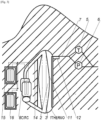
- the device comprises at least one Thermodynamic Work RPP (1THERMO) and one Hydraulic Transit RPP (1TRANSIT), each containing at least one hydraulic liquid (3), and at least one propellant fluid (2), comprises at least one liquid communication (7) equipped with at least one hydroelectric conversion machine (5) (6) and comprises at least two heat exchange systems (8COND) (8EVAP) in contact with the propellant fluid (2).
- Thermodynamic Work RPP (1THERMO) and one Hydraulic Transit RPP (1TRANSIT) each containing at least one hydraulic liquid (3), and at least one propellant fluid (2)
- the device may also comprise a receiving basin (4) for the hydraulic fluid (3) replacing the Hydraulic Transit RPP in the event of a significant difference in level between the basin and the Thermodynamic Work RPP, external heat recirculation exchangers (8CIRC) for the propellant fluid (2) through the Thermodynamic Work RPP (1THERMO), several differentiated compartments (9) for storing, according to their colder and hotter temperature, the possible heat transfer fluid(s) circulating in contact with the heat exchange systems (8COND) (8EVAP) (8CIRC).
- the device generally includes hot thermal reserves (15) or cold thermal reserves (16), in particular for carrying out thermoelectric storage, and concerning the cold thermal reserves (16), for carrying out the low pressure maintenance of the Transit RPP Hydraulics (1TRANSIT).
- the device may include secondary pressurized tanks (13) dedicated to the propellant fluids (2) necessarily connected to the RPPs by means of pipes (14).
- the device may also include, in the upper portion of the tanks (1THERMO) (1TRANSIT) (13), systems for spraying and dropping by gravity droplets (10) of the propellant fluid (2) or the hydraulic liquid (3).
- the device may also include one or more movable physical separations (11) between the hydraulic liquid (3) and the propellant fluid(s) (2).
- the closing of the pressurized tanks (1THERMO) (1TRANSIT) (13) of the device may be carried out by means of an airlock (12).
- the FP13 plot reproduces the states of the propellant fluid (2) in the secondary pressurized tanks (13)
- the FP1THERMO plot reproduces the states of the propellant fluid (2) in the RPP of Thermodynamic Work (1THERMO)
- the VIS1TRANSIT plot allows to visualize the transfers of the hydraulic fluid (3) between the 2 RPPs (1THERMO) (1TRANSIT), without reproducing the states of the propellant fluid (2) in the Hydraulic Transit RPP (1TRANSIT), these states being quasi-constant, of low temperature and low pressure.
- Section BC illustrates a partial isentropic compression.
- Section CD illustrates an interesting and unusual heat extraction at maximum temperature during a diabatic compression.
- Section DE illustrates a classic production of Hot by an isobaric heat extraction in supercritical phase thanks to the use of the condenser (8COND), located at high pressure.
- Section EF illustrates a cooling to the dense (or liquid) state of the propellant fluid (2).
- Section FG illustrates the cooling of the propellant fluid (2) in the secondary pressurized tanks (13).
- Section GH illustrates a classic isenthalpic expansion to lower the temperature of the propellant fluid (2) to its minimum.
- Section HA illustrates an isobaric gasification for the production of Cold thanks to the evaporator (8EVAP), located at low pressure. It is important to note that a second voluntary permutation of the two RPPs (1THERMO) (1TRANSIT) is necessarily carried out between point F and point A.
- the FP13 plot reproduces the states of the propellant fluid (2) in the secondary pressurized tanks (13)
- the FP1THERMO plot reproduces the states of the propellant fluid (2) in the RPP of Thermodynamic Work
- the VIS1TRANSIT plot allows to visualize the transfers of the hydraulic fluid (3) between the 2 RPP (1THERMO) (1TRANSIT), without however reproducing the states of the propellant fluid (2) in the RPP of Hydraulic Transit (1TRANSIT), these states being most often constant, of low temperature and low pressure.
- the gaseous and hot propellant fluid (2) is transferred entirely via this additional exchanger, thanks to a mechanical transfer of the hydraulic fluid (3) by a small pump and ancillary hydraulic pipe, between the Thermodynamic Work RPP (1THERMO) and the Hydraulic Transit RPP (1TRANSIT), originally completely filled with hydraulic fluid (3) as a result of the hydraulic turbine of the previous cycle.
- Section IJ illustrates this heating of the propellant fluid (2) in the secondary pressurized tanks (13).
- Section JK illustrates a reheating in the supercritical phase.
- Section KL illustrates a supercritical isobaric reheating and an expansion of the propellant fluid (2), thanks to the evaporator (8EVAP) located at high pressure and thanks to a consumption of heat coming for example from the hot thermal reserve (15).
- Section LM illustrates a diabatic expansion, interesting and unusual, because it is not classically isentropic, to provide more work thanks to an additional supply of heat.
- Section MN illustrates the isochoric cooling on the right side mentioned above.
- Section NI illustrates a contraction of the propellant fluid (2) through an extraction of heat at the condenser (8COND) located at low pressure, an extraction which will cause a consumption of the cold thermal reserve (16). It is important to note that a second voluntary permutation of the two RPPs (1THERMO) (1TRANSIT) is necessarily carried out between point N and point J.
- a first example of operation concerns, according to Fig. 2 , and for the two-state Liquid-Gas mode, the thermal storage of electrical energy.
- the device will carry out a main period of pumping the hydraulic liquid (3), a period controlled by several valves not indicated in the figures.
- the pumping assembly (6) driven by the external energy to be stored pushes the hydraulic liquid (3) at low pressure coming from the RPP of Hydraulic Transit (1TRANSIT) towards the RPP of Thermodynamic Work (1THERMO) via liquid communication conduits (7), thus reducing in the RPP of Thermodynamic Work (1THERMO) the volume occupied by its propellant fluid (2).
- thermodynamic cycles includes isochoric heat exchanges and two successive permutations of the 2 RPPs (1THERMO1) (1TRANSIT), allowing the production of Cold as explained in figure 5 and its description.
- a second example of operation concerns, according to the same Fig. 2 , and for the mode of the two Liquid-Gas states, the electrical restitution of stored thermal energy.
- the propellant fluid (2) of the Thermodynamic Work RPP (1THERMO) simultaneously subjected to an intense heat input from the hot thermal reserve (16) thanks to the heat exchange systems (8EVAP) (8CIRC) will pass from the liquid state to the gaseous state, and will thus expel at its saturated vapor pressure towards the Hydraulic Transit RPP (1TRANSIT) the hydraulic liquid (3) coming from this Thermodynamic Work RPP (1THERMO) via the liquid communication conduits (7) and via the turbine assembly (5) which thus recovers the stored energy.
- thermodynamic cycles includes isochoric heat exchanges and two successive permutations of the 2 RPPs (1THERMO) (1TRANSIT) and causes a consumption of the cold thermal reserve (16) as explained in figure 6 and its description.
- thermoelectric storage requires the use of one or more masses of liquid or solid matter, including salt water in the liquid and solid state, preferably organized according to differentiated temperatures, possibly including thermocline reservoirs or areas of the earth's soil.
- the quantity of Cold produced is, in the case of CO2 used as a propellant fluid, approximately 5 times greater than the quantity of electrical energy stored.
- thermoelectric storage thermally in the hot thermal reserves (15) of this thermoelectric storage, during periods of compression of the propellant fluid.
- This storage requires the use of one or more masses of liquid or solid matter, preferably organized according to differentiated temperatures, possibly including thermocline reservoirs or areas of the earth's soil.
- the quantity of Hot produced is, in the case of CO2 used as a propellant fluid, approximately 5 times greater than the quantity of available electrical energy.
- the device according to the invention is intended for energy storage and conversion to store, produce or move electrical or thermal energy.
- a second industrial application is to provide an economic solution to the necessary decarbonization of the Cold and Heat needs of industries and residential and tertiary buildings.
- the consumption of Cold and Heat, large consumers of fossil energy represents 40% of greenhouse gas emissions.
- a third industrial application is the net generation of electricity, from the availability of a hot or cold source, including in situations of low temperature difference (low temperature geothermal energy, warm effluents, thermal energy from the sea) in which conventional thermal engines, economically requiring differences greater than 25°C, could not operate.
- low temperature difference low temperature geothermal energy, warm effluents, thermal energy from the sea
Landscapes
- Engineering & Computer Science (AREA)
- Mechanical Engineering (AREA)
- General Engineering & Computer Science (AREA)
- Physics & Mathematics (AREA)
- Thermal Sciences (AREA)
- Chemical & Material Sciences (AREA)
- Combustion & Propulsion (AREA)
- Engine Equipment That Uses Special Cycles (AREA)
- Electromechanical Clocks (AREA)
- Power Steering Mechanism (AREA)
Claims (15)
- Die Einrichtung besteht aus - mindestens zwei unter Druck gesetzten Haupttanks mit der Abkürzung RPP, von denen der eine als Thermodynamischer Arbeits-RPP (1THERMO) und der andere als Hydraulischer Transit-RPP (1TRANSIT) bezeichnet wird, die jeweils mindestens ein nicht verlorenes Treibmittel (2) enthalten und sich mindestens eine Hydraulikflüssigkeit (3) teilen, die sich zwischen ihnen in entgegengesetzter Richtung über mindestens eine flüssige Verbindung (7) bewegt, die mit mindestens einer hydroelektrischen Konversionsmaschine wie einer Pumpeinheit (6) oder einer Turbineneinheit (5) ausgestattet ist, - durch ein Wärmeaustauschsystem, das mit den Treibflüssigkeiten (2) im Austausch steht und mindestens einen Verdampfer (8EVAP) und mindestens einen Kondensator (8COND) umfasst, dadurch gekennzeichnet, - dass die thermodynamische Sequenz, die aus einer Expansion und dann einer Kontraktion jeder der Treibflüssigkeiten (2) besteht, langsam, diskontinuierlich und quantitativ begrenzt in der Masse durch die Veränderung des Volumens, das sie in den breiten RPP (1THERMO) (LTRANSIT) enthält, erfolgt - indem die Treibmittel (2) entweder durch abwechselnde Zustandsänderungen von mindestens zwei Zuständen aus den drei Zuständen flüssig, gasförmig und überkritisch arbeiten, oder im ausschließlich überkritischen Zustand durch breite, abwechselnde Änderungen ihrer überkritischen Volumenmasse arbeiten, - und indem der Druck des Treibfluids (2) des RPP für hydraulischen Transit (1TRANSIT) nahezu konstant und nahe dem Minimalwert ist, der im Druckbereich des Treibfluids (2) des RPP für thermodynamische Arbeit (1THERMO) angetroffen wird.
- Einrichtung nach Anspruch 1, dadurch gekennzeichnet, dass die Einrichtung mindestens eine kalte thermische Reserve (16) oder mindestens eine warme thermische Reserve (15) zur Speicherung von Wärmeenergie über eine oder mehrere Massen flüssiger oder fester Materie enthält, (16), darunter die Möglichkeit von Thermoklinenreservoirs oder Erdbodenzonen, enthält, und dass es sich um Wärmezufuhr und -entzug gegenüber diesen Wärmereserven (15) (16) handelt, die auf der Ebene der Wärmeaustauschsysteme (8EVAP) (8COND) (8CIRC) den Großteil der Wärmeentnahme oder -zufuhr zu den Treibmitteln realisieren (2).
- Einrichtung nach Anspruch 1, dadurch gekennzeichnet, dass es warme thermische Quellen oder kalte thermische Quellen außerhalb der Haupteinrichtung sind, z. B. in Form von thermischer Solarenergie, oder in Form von Eis, kaltem Wasser oder kalter Luft, oder in Form von Dampf, Wasser oder heißer Luft, oder in Form von natürlicher oder künstlicher Geothermie, oder in Form von überschüssigen Energie aus Drittprozessen, usw., die den Wärmeaustausch mit der Haupteinrichtung bewirken, die in den Wärmetauschersystemen (8EVAP) (8COND),(8CIRC) den Großteil der dem Treibmittel entzogenen oder zugeführten Wärme erzeugen (2).
- Einrichtung nach Anspruch 2 oder 3, dadurch gekennzeichnet, dass ein Zusammenspiel von verschiedenen Wärmeaustauschmitteln, darunter Kondensatoren (8CCOND), Verdampfer (8EVAP), Rezirkulationsaustauscher (8CIRC) und physikalische Umfüllungen der Treibflüssigkeiten (2) über zwischen zwei RPPs eingefügte Austauscher die Wärmezufuhr oder -entnahme für diese Treibflüssigkeiten (2) in allen Segmenten der thermodynamischen Zyklen ermöglichen, einschließlich der Segmente, die die Bewegungen der Hydraulikflüssigkeit (3) realisieren.
- Einrichtung nach irgendeinem der vorhergehenden Ansprüche, dadurch gekennzeichnet, dass Massen von Wärmeträgerflüssigkeiten oder Massen von Hydraulikflüssigkeit (3), die mit den Treibflüssigkeiten (2) Wärme ausgetauscht haben, entsprechend ihren kälteren oder wärmeren Temperaturen in mehreren differenzierten Abteilen (9) zwischengelagert werden.
- Einrichtung nach Anspruch 2 oder Anspruch 5, dadurch gekennzeichnet, dass alle oder ein Teil der nach ihren Temperaturen differenzierten Abteile zur vorübergehenden Lagerung von Fluiden (9) oder alle oder ein Teil der Wärmereserven (15) (16) Phase-Change-Materialien verwenden, darunter möglicherweise Salzwassereis, oder ein wässriges Gemisch in den Zuständen Flüssig-Fest verwenden.
- Einrichtung nach irgendeinem der vorhergehenden Ansprüche, dadurch gekennzeichnet, dass die Treibflüssigkeiten (2) von der Hinzufügung eines oder mehrerer dedizierter sekundärer unter Druck gesetzten Tanks (13) profitieren, die mit den RPPs (1THERMO) (1TRANSIT) über eine oder mehrere Leitungen (14) in Verbindung stehen, die mit Ventilen und eventuellen Mechanismen für erzwungene Konvektionen zwischen den sekundären unter Druck gesetzten Tanks (13) und diesen RPPs (1THERMO) (1TRANSIT) ausgestattet sind.
- Einrichtung nach irgendeinem der vorhergehenden Ansprüche, dadurch gekennzeichnet, dass der obere Abschnitt aller oder eines Teils der unter Druck gesetzten Tanks (1THERMO) (LTRANSIT) (13) mit einem System zum Besprühen und Fallenlassen durch Schwerkraft von Tröpfchen (10) des Treibmittels (2) oder der Hydraulikflüssigkeit (3) oder mit anderen physikalischen Techniken zur Verbesserung der Wärmeübertragung wie Platten oder Auskleidungen versehen ist.
- Einrichtung nach irgendeinem der vorhergehenden Ansprüche, dadurch gekennzeichnet, dass das oder die Treibmittel (2) chemische Körper oder Mischungen von chemischen Körpern sind, die so ausgewählt sind, dass sie bei den in dem oder den unter Druck gesetzten Tanks (1THERMO) (LTRANSIT) (13) angetroffenen Maximaltemperaturen, Sättigungsdampfdrücke aufweisen, die niedriger sind als die maximal zulässigen Drücke in diesen unter Druck gesetzten Tanks (1THERMO) (1TRANSIT) (13), wie zum Beispiel Kohlendioxid, Ethan oder Mischungen von Kohlendioxid mit Kohlenwasserstoffen, mit Stickstoffverbindungen oder mit Alkoholen.
- Einrichtung nach irgendeinem der vorhergehenden Ansprüche, dadurch gekennzeichnet, dass alle oder ein Teil der Treibmittel (2) durch eine Wärmezufuhr oder -entnahme erwärmt oder gekühlt werden, die die hohen oder niedrigen Temperaturen von Fluiden nutzt, die aus einem anderen Abschnitt des thermodynamischen Zyklus oder aus ihrer Mehrzahl stammen, z. B. durch einen gegenseitigen Erwärmungs-Kühlungs-Austauscher zwischen zwei verschiedenen Massen von Treibmittel (2), oder die aus warmen oder kalten Fluiden stammen, die bei früheren Operationen gespeichert wurden, oder die eine externe thermische Quelle oder die umgebende Umwelt nutzt.
- Einrichtung nach irgendeinem der vorhergehenden Ansprüche, dadurch gekennzeichnet, dass Mittel zur Verringerung der Auflösungen zwischen den Treibflüssigkeiten (2) und der Hydraulikflüssigkeit (3) vorgesehen sind, wie bewegliche physikalische Trennungen (11) zwischen diesen Flüssigkeiten, Erhöhungen des chemischen PH-Werts oder die Verwendung von Additiven.
- Einrichtung nach Anspruch 1 oder Anspruch 7, dadurch gekennzeichnet, dass mindestens einer der unter Druck gesetzten Tanks (1THERMO) (1TRANSIT) (13) aus einer natürlichen oder künstlichen unterirdischen Kaverne oder einem Unterwassertank besteht.
- Einrichtung nach Anspruch 1 oder Anspruch 2, dadurch gekennzeichnet, dass mindestens ein hydraulischer Transit-RPP (1TRANSIT) oder mindestens eine thermische Reserve (15) (16) aus einem Becken, einem Fluss oder einer natürlichen Wasserfläche besteht.
- Kombination mit einer Vielzahl von Einrichtungen nach irgendeinem der vorhergehenden Ansprüche, wobei die Elemente der Einrichtungen wie die RPPs (1THERMO) (1TRANSIT), die sekundären unter Druck gesetzten Tanks (13), die Hydraulikflüssigkeiten (3), die Treibflüssigkeiten (2), die Wärmetauschsysteme (8COND) (8EVAP) (8CIRC), die nach ihren Temperaturen differenzierten Abteilungen zur Lagerung der Flüssigkeiten (9), die Flüssigkeitskommunikationen (7), die Leitungen (14) für das Treibfluid (2), die Pumpensätze (6), die Turbinensätze (5) , die kalten thermischen Reserven (16), die heißen thermischen Reserven (15), die Auffangbecken (4) untereinander durch mit Ventilen versehene Leitungen verbunden sind.
- Verwendung einer Einrichtung nach einem der Ansprüche 1 bis 13 oder einer Kombination nach Anspruch 14 zum Speichern oder Umwandeln von Energie.
Applications Claiming Priority (3)
| Application Number | Priority Date | Filing Date | Title |
|---|---|---|---|
| FR1906627A FR3097593A1 (fr) | 2019-06-19 | 2019-06-19 | Dispositif hybride de stockage ou de conversion énergétiques, à fluide propulseur liquide, gazeux ou supercritique |
| FR2005434 | 2020-05-21 | ||
| PCT/IB2020/055815 WO2020255086A1 (fr) | 2019-06-19 | 2020-06-19 | Dispositif thermoélectrique de stockage ou conversions énergétiques |
Publications (2)
| Publication Number | Publication Date |
|---|---|
| EP4168665A1 EP4168665A1 (de) | 2023-04-26 |
| EP4168665B1 true EP4168665B1 (de) | 2024-08-14 |
Family
ID=71614924
Family Applications (1)
| Application Number | Title | Priority Date | Filing Date |
|---|---|---|---|
| EP20740395.7A Active EP4168665B1 (de) | 2019-06-19 | 2020-06-19 | Thermoelektrische vorrichtung zur speicherung oder umwandlung von energie |
Country Status (5)
| Country | Link |
|---|---|
| US (1) | US12352503B2 (de) |
| EP (1) | EP4168665B1 (de) |
| AU (1) | AU2020295027A1 (de) |
| CA (1) | CA3187771A1 (de) |
| WO (1) | WO2020255086A1 (de) |
Families Citing this family (2)
| Publication number | Priority date | Publication date | Assignee | Title |
|---|---|---|---|---|
| CN116086226B (zh) * | 2023-01-09 | 2023-10-20 | 中国电建集团华东勘测设计研究院有限公司 | 一种用于抽水压缩空气储能的水气换热系统及方法 |
| CN119419874B (zh) * | 2024-11-06 | 2025-05-13 | 华北电力大学 | 一种耦合可逆固体氧化物电池技术与闭式co2网络的区域多能互补系统 |
Family Cites Families (33)
| Publication number | Priority date | Publication date | Assignee | Title |
|---|---|---|---|---|
| US4199021A (en) | 1976-11-24 | 1980-04-22 | Johnson Controls, Inc. | Thermal energy storage apparatus |
| US4251291A (en) | 1979-02-01 | 1981-02-17 | Gomez Ernesto E | Thermoelectric generator with latent heat storage |
| US5269146A (en) | 1990-08-28 | 1993-12-14 | Kerner James M | Thermoelectric closed-loop heat exchange system |
| JPH0817481A (ja) | 1994-06-29 | 1996-01-19 | Nippon Telegr & Teleph Corp <Ntt> | 熱電変換装置 |
| US5737923A (en) | 1995-10-17 | 1998-04-14 | Marlow Industries, Inc. | Thermoelectric device with evaporating/condensing heat exchanger |
| US7100369B2 (en) | 2003-05-06 | 2006-09-05 | Denso Corporation | Thermoelectric generating device |
| DE102004047290A1 (de) | 2003-09-24 | 2005-05-04 | Karl Ludwig Holder | Verfahren zum Betreiben einer Kraftstation und Kraftstation zur Durchführung des Verfahrens |
| US7405013B2 (en) | 2004-06-07 | 2008-07-29 | Gm Global Technology Operations, Inc. | Thermoelectric conversion of heat released during use of a power-plant or hydrogen storage material |
| US20070101737A1 (en) | 2005-11-09 | 2007-05-10 | Masao Akei | Refrigeration system including thermoelectric heat recovery and actuation |
| US20080142067A1 (en) | 2006-12-14 | 2008-06-19 | Robert Dell | Thermoelectric power generation device |
| DE102009013692A1 (de) | 2009-03-20 | 2010-09-23 | Emitec Gesellschaft Für Emissionstechnologie Mbh | Thermoelektrische Vorrichtung |
| FR2945326B1 (fr) | 2009-05-07 | 2011-04-29 | Ecoren | Procede et equipement de stockage d'energie mecanique par compression et detente quasi-isotherme d'un gaz |
| TW201043783A (en) | 2009-06-12 | 2010-12-16 | Chung Hsin Elec & Mach Mfg | Thermoelectric generator device for absorbing heat |
| GB0919934D0 (en) | 2009-11-16 | 2009-12-30 | Sunamp Ltd | Energy storage systems |
| US8286424B2 (en) | 2010-04-02 | 2012-10-16 | GM Global Technology Operations LLC | Thermoelectric generator cooling system and method of control |
| US9611868B2 (en) * | 2010-04-09 | 2017-04-04 | Shipstone Corporation | System and method for energy storage and retrieval |
| DE102010021901A1 (de) | 2010-05-28 | 2011-12-01 | Volkswagen Ag | Wärmetauschen zwischen Fluidströmen mittels einer thermoelektrischen Vorrichtung |
| EP2400120A1 (de) | 2010-06-23 | 2011-12-28 | ABB Research Ltd. | Thermoelektrisches Energiespeichersystem |
| US8646261B2 (en) | 2010-09-29 | 2014-02-11 | GM Global Technology Operations LLC | Thermoelectric generators incorporating phase-change materials for waste heat recovery from engine exhaust |
| US20120102933A1 (en) | 2010-10-27 | 2012-05-03 | Basf Se | Thermoelectric generator |
| KR20140032954A (ko) | 2010-11-16 | 2014-03-17 | 포톤 홀딩 엘엘씨 | 발광다이오드 광을 제공하기 위한 시스템들, 방법들, 및/또는 디바이스들 |
| DE102011018679A1 (de) * | 2011-04-21 | 2012-10-25 | Dennis Patrick Steel | Anlage zur Speicherung von Energie, vorzugsweise erneuerbarer Energie |
| KR101654587B1 (ko) | 2011-06-06 | 2016-09-06 | 젠썸 인코포레이티드 | 카트리지 기반 열전 시스템 |
| JP2013077810A (ja) | 2011-09-12 | 2013-04-25 | Yamaha Corp | 熱電装置 |
| US9685599B2 (en) | 2011-10-07 | 2017-06-20 | Gentherm Incorporated | Method and system for controlling an operation of a thermoelectric device |
| DE112013000620T5 (de) | 2012-01-20 | 2014-10-16 | Gentherm Incorporated | Integrierter Katalysator/Thermoelektrischer Generator |
| CN105378954B (zh) | 2013-03-15 | 2017-12-29 | 维卡里亚斯公司 | 热电装置 |
| CN106537621B (zh) | 2014-03-25 | 2018-12-07 | 美特瑞克斯实业公司 | 热电设备和系统 |
| JP2016017737A (ja) | 2014-07-07 | 2016-02-01 | 現代自動車株式会社Hyundaimotor Company | Ted熱交換器 |
| DE102014218727A1 (de) | 2014-09-18 | 2016-03-24 | Siemens Aktiengesellschaft | Thermoelektrischer Generator und Verfahren zum Betreiben eines thermoelektrischen Generators |
| CN105927390B (zh) * | 2016-06-27 | 2017-11-28 | 南京涵曦月自动化科技有限公司 | 一种压缩空气能量储存发电系统 |
| FR3082559B1 (fr) * | 2019-02-16 | 2022-10-21 | Pascal Lalanne | Dispositif hybride de stockage énergétique et de déplacement de chaleur à fluides liquides, gazeux et supercritiques |
| FR3097593A1 (fr) * | 2019-06-19 | 2020-12-25 | Pascal Lalanne | Dispositif hybride de stockage ou de conversion énergétiques, à fluide propulseur liquide, gazeux ou supercritique |
-
2020
- 2020-06-19 WO PCT/IB2020/055815 patent/WO2020255086A1/fr not_active Ceased
- 2020-06-19 US US18/011,095 patent/US12352503B2/en active Active
- 2020-06-19 EP EP20740395.7A patent/EP4168665B1/de active Active
- 2020-06-19 AU AU2020295027A patent/AU2020295027A1/en active Pending
- 2020-06-19 CA CA3187771A patent/CA3187771A1/en active Pending
Also Published As
| Publication number | Publication date |
|---|---|
| WO2020255086A4 (fr) | 2021-02-18 |
| WO2020255086A1 (fr) | 2020-12-24 |
| AU2020295027A1 (en) | 2023-02-23 |
| US12352503B2 (en) | 2025-07-08 |
| EP4168665A1 (de) | 2023-04-26 |
| CA3187771A1 (en) | 2020-12-24 |
| US20230243599A1 (en) | 2023-08-03 |
Similar Documents
| Publication | Publication Date | Title |
|---|---|---|
| EP3052773B1 (de) | Thermodynamisches system zur speicherung/erzeugung elektrischer energie | |
| US8683803B2 (en) | Method and apparatus for energy harvesting through phase-change induced pressure rise under cooling conditions | |
| Chen et al. | A novel isobaric adiabatic compressed air energy storage (IA-CAES) system on the base of volatile fluid | |
| US11591957B2 (en) | Energy storage apparatus and method | |
| CN104854344A (zh) | 压力单元 | |
| EP3303825B1 (de) | Vorrichtung und verfahren zur umwandlung und speicherung elektrischer energie in form von druckluft | |
| EP3164583A1 (de) | System und verfahren zur speicherung und rückgewinnung von energie anhand von komprimiertem gas, mit wärmespeicherung mittels einer wärmeübertragungsflüssigkeit | |
| Ghilardi et al. | Integration of ocean thermal energy conversion and pumped thermal energy storage: system design, off-design and LCOS evaluation | |
| EP4168665B1 (de) | Thermoelektrische vorrichtung zur speicherung oder umwandlung von energie | |
| FR2945326A1 (fr) | Procede et equipement de stockage d'energie mecanique par compression et detente quasi-isotherme d'un gaz | |
| JP2023514812A (ja) | エネルギー貯蔵プラント及びエネルギー貯蔵方法 | |
| JPWO2020039416A5 (de) | ||
| FR3082559A1 (fr) | Dispositif hybride de stockage énergétique et de déplacement de chaleur à fluides liquides, gazeux et supercritiques | |
| JP2020076400A (ja) | 蒸発若しくは昇華および凝縮に浮力ファクターを用いた熱エネルギからの機械的/電気的エネルギの生成 | |
| FR3097593A1 (fr) | Dispositif hybride de stockage ou de conversion énergétiques, à fluide propulseur liquide, gazeux ou supercritique | |
| FR2851796A1 (fr) | Pompe hydraulique et installation hydraulique comportant une telle pompe. | |
| Li et al. | Synergistic thermodynamic analysis of integrated power-water cogeneration: Near-Isothermal compression for desalination and energy storage | |
| EP3724471A1 (de) | Verbessertes system zur speicherung und gewinnung von energie | |
| FR3133430A1 (fr) | Pompe a chaleur a deux systemes de stockage et restitution d’energie thermique | |
| Cheayb | Integrated storage system for renewable electricity by compressed air | |
| EP4490449B1 (de) | Wärmepumpe mit zwei wärmeenergiespeicher- und -abgabesystemen | |
| EP0244435B1 (de) | Erzeuger von energie unterschiedlicher art mit einbezogenem wärmekreislauf | |
| JP2024109811A (ja) | 蒸発若しくは昇華および凝縮に浮力ファクターを用いた熱エネルギからの機械的/電気的エネルギの生成 | |
| CN119468771A (zh) | 能量储存和回收系统及方法 | |
| SK285598B6 (sk) | Spôsob a zariadenie na tlakové energetické premeny tekutín |
Legal Events
| Date | Code | Title | Description |
|---|---|---|---|
| STAA | Information on the status of an ep patent application or granted ep patent |
Free format text: STATUS: UNKNOWN |
|
| STAA | Information on the status of an ep patent application or granted ep patent |
Free format text: STATUS: THE INTERNATIONAL PUBLICATION HAS BEEN MADE |
|
| PUAI | Public reference made under article 153(3) epc to a published international application that has entered the european phase |
Free format text: ORIGINAL CODE: 0009012 |
|
| STAA | Information on the status of an ep patent application or granted ep patent |
Free format text: STATUS: REQUEST FOR EXAMINATION WAS MADE |
|
| 17P | Request for examination filed |
Effective date: 20230116 |
|
| AK | Designated contracting states |
Kind code of ref document: A1 Designated state(s): AL AT BE BG CH CY CZ DE DK EE ES FI FR GB GR HR HU IE IS IT LI LT LU LV MC MK MT NL NO PL PT RO RS SE SI SK SM TR |
|
| DAV | Request for validation of the european patent (deleted) | ||
| DAX | Request for extension of the european patent (deleted) | ||
| GRAP | Despatch of communication of intention to grant a patent |
Free format text: ORIGINAL CODE: EPIDOSNIGR1 |
|
| STAA | Information on the status of an ep patent application or granted ep patent |
Free format text: STATUS: GRANT OF PATENT IS INTENDED |
|
| INTG | Intention to grant announced |
Effective date: 20240328 |
|
| GRAS | Grant fee paid |
Free format text: ORIGINAL CODE: EPIDOSNIGR3 |
|
| GRAA | (expected) grant |
Free format text: ORIGINAL CODE: 0009210 |
|
| STAA | Information on the status of an ep patent application or granted ep patent |
Free format text: STATUS: THE PATENT HAS BEEN GRANTED |
|
| AK | Designated contracting states |
Kind code of ref document: B1 Designated state(s): AL AT BE BG CH CY CZ DE DK EE ES FI FR GB GR HR HU IE IS IT LI LT LU LV MC MK MT NL NO PL PT RO RS SE SI SK SM TR |
|
| REG | Reference to a national code |
Ref country code: GB Ref legal event code: FG4D Free format text: NOT ENGLISH |
|
| REG | Reference to a national code |
Ref country code: CH Ref legal event code: EP |
|
| REG | Reference to a national code |
Ref country code: DE Ref legal event code: R096 Ref document number: 602020035780 Country of ref document: DE |
|
| REG | Reference to a national code |
Ref country code: IE Ref legal event code: FG4D Free format text: LANGUAGE OF EP DOCUMENT: FRENCH |
|
| REG | Reference to a national code |
Ref country code: LT Ref legal event code: MG9D |
|
| REG | Reference to a national code |
Ref country code: NL Ref legal event code: MP Effective date: 20240814 |
|
| PG25 | Lapsed in a contracting state [announced via postgrant information from national office to epo] |
Ref country code: NO Free format text: LAPSE BECAUSE OF FAILURE TO SUBMIT A TRANSLATION OF THE DESCRIPTION OR TO PAY THE FEE WITHIN THE PRESCRIBED TIME-LIMIT Effective date: 20241114 |
|
| REG | Reference to a national code |
Ref country code: AT Ref legal event code: MK05 Ref document number: 1713508 Country of ref document: AT Kind code of ref document: T Effective date: 20240814 |
|
| PG25 | Lapsed in a contracting state [announced via postgrant information from national office to epo] |
Ref country code: GR Free format text: LAPSE BECAUSE OF FAILURE TO SUBMIT A TRANSLATION OF THE DESCRIPTION OR TO PAY THE FEE WITHIN THE PRESCRIBED TIME-LIMIT Effective date: 20241115 Ref country code: NL Free format text: LAPSE BECAUSE OF FAILURE TO SUBMIT A TRANSLATION OF THE DESCRIPTION OR TO PAY THE FEE WITHIN THE PRESCRIBED TIME-LIMIT Effective date: 20240814 Ref country code: FI Free format text: LAPSE BECAUSE OF FAILURE TO SUBMIT A TRANSLATION OF THE DESCRIPTION OR TO PAY THE FEE WITHIN THE PRESCRIBED TIME-LIMIT Effective date: 20240814 Ref country code: PT Free format text: LAPSE BECAUSE OF FAILURE TO SUBMIT A TRANSLATION OF THE DESCRIPTION OR TO PAY THE FEE WITHIN THE PRESCRIBED TIME-LIMIT Effective date: 20241216 Ref country code: PL Free format text: LAPSE BECAUSE OF FAILURE TO SUBMIT A TRANSLATION OF THE DESCRIPTION OR TO PAY THE FEE WITHIN THE PRESCRIBED TIME-LIMIT Effective date: 20240814 |
|
| PG25 | Lapsed in a contracting state [announced via postgrant information from national office to epo] |
Ref country code: BG Free format text: LAPSE BECAUSE OF FAILURE TO SUBMIT A TRANSLATION OF THE DESCRIPTION OR TO PAY THE FEE WITHIN THE PRESCRIBED TIME-LIMIT Effective date: 20240814 |
|
| PG25 | Lapsed in a contracting state [announced via postgrant information from national office to epo] |
Ref country code: LV Free format text: LAPSE BECAUSE OF FAILURE TO SUBMIT A TRANSLATION OF THE DESCRIPTION OR TO PAY THE FEE WITHIN THE PRESCRIBED TIME-LIMIT Effective date: 20240814 |
|
| PG25 | Lapsed in a contracting state [announced via postgrant information from national office to epo] |
Ref country code: IS Free format text: LAPSE BECAUSE OF FAILURE TO SUBMIT A TRANSLATION OF THE DESCRIPTION OR TO PAY THE FEE WITHIN THE PRESCRIBED TIME-LIMIT Effective date: 20241214 Ref country code: AT Free format text: LAPSE BECAUSE OF FAILURE TO SUBMIT A TRANSLATION OF THE DESCRIPTION OR TO PAY THE FEE WITHIN THE PRESCRIBED TIME-LIMIT Effective date: 20240814 |
|
| PG25 | Lapsed in a contracting state [announced via postgrant information from national office to epo] |
Ref country code: HR Free format text: LAPSE BECAUSE OF FAILURE TO SUBMIT A TRANSLATION OF THE DESCRIPTION OR TO PAY THE FEE WITHIN THE PRESCRIBED TIME-LIMIT Effective date: 20240814 |
|
| PG25 | Lapsed in a contracting state [announced via postgrant information from national office to epo] |
Ref country code: ES Free format text: LAPSE BECAUSE OF FAILURE TO SUBMIT A TRANSLATION OF THE DESCRIPTION OR TO PAY THE FEE WITHIN THE PRESCRIBED TIME-LIMIT Effective date: 20240814 Ref country code: RS Free format text: LAPSE BECAUSE OF FAILURE TO SUBMIT A TRANSLATION OF THE DESCRIPTION OR TO PAY THE FEE WITHIN THE PRESCRIBED TIME-LIMIT Effective date: 20241114 |
|
| PG25 | Lapsed in a contracting state [announced via postgrant information from national office to epo] |
Ref country code: RS Free format text: LAPSE BECAUSE OF FAILURE TO SUBMIT A TRANSLATION OF THE DESCRIPTION OR TO PAY THE FEE WITHIN THE PRESCRIBED TIME-LIMIT Effective date: 20241114 Ref country code: PT Free format text: LAPSE BECAUSE OF FAILURE TO SUBMIT A TRANSLATION OF THE DESCRIPTION OR TO PAY THE FEE WITHIN THE PRESCRIBED TIME-LIMIT Effective date: 20241216 Ref country code: PL Free format text: LAPSE BECAUSE OF FAILURE TO SUBMIT A TRANSLATION OF THE DESCRIPTION OR TO PAY THE FEE WITHIN THE PRESCRIBED TIME-LIMIT Effective date: 20240814 Ref country code: NO Free format text: LAPSE BECAUSE OF FAILURE TO SUBMIT A TRANSLATION OF THE DESCRIPTION OR TO PAY THE FEE WITHIN THE PRESCRIBED TIME-LIMIT Effective date: 20241114 Ref country code: NL Free format text: LAPSE BECAUSE OF FAILURE TO SUBMIT A TRANSLATION OF THE DESCRIPTION OR TO PAY THE FEE WITHIN THE PRESCRIBED TIME-LIMIT Effective date: 20240814 Ref country code: LV Free format text: LAPSE BECAUSE OF FAILURE TO SUBMIT A TRANSLATION OF THE DESCRIPTION OR TO PAY THE FEE WITHIN THE PRESCRIBED TIME-LIMIT Effective date: 20240814 Ref country code: IS Free format text: LAPSE BECAUSE OF FAILURE TO SUBMIT A TRANSLATION OF THE DESCRIPTION OR TO PAY THE FEE WITHIN THE PRESCRIBED TIME-LIMIT Effective date: 20241214 Ref country code: HR Free format text: LAPSE BECAUSE OF FAILURE TO SUBMIT A TRANSLATION OF THE DESCRIPTION OR TO PAY THE FEE WITHIN THE PRESCRIBED TIME-LIMIT Effective date: 20240814 Ref country code: GR Free format text: LAPSE BECAUSE OF FAILURE TO SUBMIT A TRANSLATION OF THE DESCRIPTION OR TO PAY THE FEE WITHIN THE PRESCRIBED TIME-LIMIT Effective date: 20241115 Ref country code: FI Free format text: LAPSE BECAUSE OF FAILURE TO SUBMIT A TRANSLATION OF THE DESCRIPTION OR TO PAY THE FEE WITHIN THE PRESCRIBED TIME-LIMIT Effective date: 20240814 Ref country code: ES Free format text: LAPSE BECAUSE OF FAILURE TO SUBMIT A TRANSLATION OF THE DESCRIPTION OR TO PAY THE FEE WITHIN THE PRESCRIBED TIME-LIMIT Effective date: 20240814 Ref country code: BG Free format text: LAPSE BECAUSE OF FAILURE TO SUBMIT A TRANSLATION OF THE DESCRIPTION OR TO PAY THE FEE WITHIN THE PRESCRIBED TIME-LIMIT Effective date: 20240814 Ref country code: AT Free format text: LAPSE BECAUSE OF FAILURE TO SUBMIT A TRANSLATION OF THE DESCRIPTION OR TO PAY THE FEE WITHIN THE PRESCRIBED TIME-LIMIT Effective date: 20240814 |
|
| PG25 | Lapsed in a contracting state [announced via postgrant information from national office to epo] |
Ref country code: RO Free format text: LAPSE BECAUSE OF FAILURE TO SUBMIT A TRANSLATION OF THE DESCRIPTION OR TO PAY THE FEE WITHIN THE PRESCRIBED TIME-LIMIT Effective date: 20240814 Ref country code: SM Free format text: LAPSE BECAUSE OF FAILURE TO SUBMIT A TRANSLATION OF THE DESCRIPTION OR TO PAY THE FEE WITHIN THE PRESCRIBED TIME-LIMIT Effective date: 20240814 Ref country code: DK Free format text: LAPSE BECAUSE OF FAILURE TO SUBMIT A TRANSLATION OF THE DESCRIPTION OR TO PAY THE FEE WITHIN THE PRESCRIBED TIME-LIMIT Effective date: 20240814 |
|
| PG25 | Lapsed in a contracting state [announced via postgrant information from national office to epo] |
Ref country code: EE Free format text: LAPSE BECAUSE OF FAILURE TO SUBMIT A TRANSLATION OF THE DESCRIPTION OR TO PAY THE FEE WITHIN THE PRESCRIBED TIME-LIMIT Effective date: 20240814 |
|
| PG25 | Lapsed in a contracting state [announced via postgrant information from national office to epo] |
Ref country code: CZ Free format text: LAPSE BECAUSE OF FAILURE TO SUBMIT A TRANSLATION OF THE DESCRIPTION OR TO PAY THE FEE WITHIN THE PRESCRIBED TIME-LIMIT Effective date: 20240814 |
|
| PG25 | Lapsed in a contracting state [announced via postgrant information from national office to epo] |
Ref country code: SK Free format text: LAPSE BECAUSE OF FAILURE TO SUBMIT A TRANSLATION OF THE DESCRIPTION OR TO PAY THE FEE WITHIN THE PRESCRIBED TIME-LIMIT Effective date: 20240814 Ref country code: IT Free format text: LAPSE BECAUSE OF FAILURE TO SUBMIT A TRANSLATION OF THE DESCRIPTION OR TO PAY THE FEE WITHIN THE PRESCRIBED TIME-LIMIT Effective date: 20240814 |
|
| REG | Reference to a national code |
Ref country code: DE Ref legal event code: R097 Ref document number: 602020035780 Country of ref document: DE |
|
| PLBE | No opposition filed within time limit |
Free format text: ORIGINAL CODE: 0009261 |
|
| STAA | Information on the status of an ep patent application or granted ep patent |
Free format text: STATUS: NO OPPOSITION FILED WITHIN TIME LIMIT |
|
| 26N | No opposition filed |
Effective date: 20250515 |
|
| PG25 | Lapsed in a contracting state [announced via postgrant information from national office to epo] |
Ref country code: SE Free format text: LAPSE BECAUSE OF FAILURE TO SUBMIT A TRANSLATION OF THE DESCRIPTION OR TO PAY THE FEE WITHIN THE PRESCRIBED TIME-LIMIT Effective date: 20240814 |
|
| PGFP | Annual fee paid to national office [announced via postgrant information from national office to epo] |
Ref country code: GB Payment date: 20250918 Year of fee payment: 6 |
|
| PGFP | Annual fee paid to national office [announced via postgrant information from national office to epo] |
Ref country code: FR Payment date: 20250918 Year of fee payment: 7 |
|
| PGFP | Annual fee paid to national office [announced via postgrant information from national office to epo] |
Ref country code: IE Payment date: 20250918 Year of fee payment: 6 |
|
| REG | Reference to a national code |
Ref country code: CH Ref legal event code: U11 Free format text: ST27 STATUS EVENT CODE: U-0-0-U10-U11 (AS PROVIDED BY THE NATIONAL OFFICE) Effective date: 20260105 |
|
| PGFP | Annual fee paid to national office [announced via postgrant information from national office to epo] |
Ref country code: DE Payment date: 20251031 Year of fee payment: 6 |
|
| PGFP | Annual fee paid to national office [announced via postgrant information from national office to epo] |
Ref country code: LU Payment date: 20251224 Year of fee payment: 6 |
|
| PGFP | Annual fee paid to national office [announced via postgrant information from national office to epo] |
Ref country code: BE Payment date: 20251224 Year of fee payment: 6 |
|
| PG25 | Lapsed in a contracting state [announced via postgrant information from national office to epo] |
Ref country code: MC Free format text: LAPSE BECAUSE OF FAILURE TO SUBMIT A TRANSLATION OF THE DESCRIPTION OR TO PAY THE FEE WITHIN THE PRESCRIBED TIME-LIMIT Effective date: 20240814 |