EP4001634B1 - Liquid column generator - Google Patents
Liquid column generator Download PDFInfo
- Publication number
- EP4001634B1 EP4001634B1 EP20209328.2A EP20209328A EP4001634B1 EP 4001634 B1 EP4001634 B1 EP 4001634B1 EP 20209328 A EP20209328 A EP 20209328A EP 4001634 B1 EP4001634 B1 EP 4001634B1
- Authority
- EP
- European Patent Office
- Prior art keywords
- tank
- generator
- piston
- liquid
- leaktight
- Prior art date
- Legal status (The legal status is an assumption and is not a legal conclusion. Google has not performed a legal analysis and makes no representation as to the accuracy of the status listed.)
- Active
Links
- 239000007788 liquid Substances 0.000 title claims description 43
- XLYOFNOQVPJJNP-UHFFFAOYSA-N water Substances O XLYOFNOQVPJJNP-UHFFFAOYSA-N 0.000 claims description 44
- 238000009434 installation Methods 0.000 claims description 14
- 230000009471 action Effects 0.000 claims description 8
- 230000007246 mechanism Effects 0.000 claims description 4
- 230000015572 biosynthetic process Effects 0.000 claims description 3
- 238000000034 method Methods 0.000 claims description 3
- 239000007858 starting material Substances 0.000 claims description 3
- 230000000977 initiatory effect Effects 0.000 claims description 2
- 238000007789 sealing Methods 0.000 claims description 2
- 238000006073 displacement reaction Methods 0.000 claims 2
- 238000004891 communication Methods 0.000 description 8
- 238000005188 flotation Methods 0.000 description 5
- 238000010586 diagram Methods 0.000 description 3
- 230000003416 augmentation Effects 0.000 description 2
- 230000008901 benefit Effects 0.000 description 2
- 230000006835 compression Effects 0.000 description 2
- 238000007906 compression Methods 0.000 description 2
- 230000009467 reduction Effects 0.000 description 2
- 239000004793 Polystyrene Substances 0.000 description 1
- 230000000295 complement effect Effects 0.000 description 1
- 238000005516 engineering process Methods 0.000 description 1
- 238000004519 manufacturing process Methods 0.000 description 1
- 239000000463 material Substances 0.000 description 1
- 238000012986 modification Methods 0.000 description 1
- 230000004048 modification Effects 0.000 description 1
- 229910001172 neodymium magnet Inorganic materials 0.000 description 1
- 229920002223 polystyrene Polymers 0.000 description 1
- 230000008569 process Effects 0.000 description 1
- 238000005086 pumping Methods 0.000 description 1
- 230000000717 retained effect Effects 0.000 description 1
- 239000008400 supply water Substances 0.000 description 1
- 238000012360 testing method Methods 0.000 description 1
- 238000012546 transfer Methods 0.000 description 1
- 239000002351 wastewater Substances 0.000 description 1
Images


Classifications
-
- F—MECHANICAL ENGINEERING; LIGHTING; HEATING; WEAPONS; BLASTING
- F01—MACHINES OR ENGINES IN GENERAL; ENGINE PLANTS IN GENERAL; STEAM ENGINES
- F01B—MACHINES OR ENGINES, IN GENERAL OR OF POSITIVE-DISPLACEMENT TYPE, e.g. STEAM ENGINES
- F01B23/00—Adaptations of machines or engines for special use; Combinations of engines with devices driven thereby
- F01B23/10—Adaptations for driving, or combinations with, electric generators
-
- F—MECHANICAL ENGINEERING; LIGHTING; HEATING; WEAPONS; BLASTING
- F03—MACHINES OR ENGINES FOR LIQUIDS; WIND, SPRING, OR WEIGHT MOTORS; PRODUCING MECHANICAL POWER OR A REACTIVE PROPULSIVE THRUST, NOT OTHERWISE PROVIDED FOR
- F03B—MACHINES OR ENGINES FOR LIQUIDS
- F03B17/00—Other machines or engines
- F03B17/02—Other machines or engines using hydrostatic thrust
- F03B17/025—Other machines or engines using hydrostatic thrust and reciprocating motion
-
- F—MECHANICAL ENGINEERING; LIGHTING; HEATING; WEAPONS; BLASTING
- F01—MACHINES OR ENGINES IN GENERAL; ENGINE PLANTS IN GENERAL; STEAM ENGINES
- F01B—MACHINES OR ENGINES, IN GENERAL OR OF POSITIVE-DISPLACEMENT TYPE, e.g. STEAM ENGINES
- F01B25/00—Regulating, controlling, or safety means
- F01B25/02—Regulating or controlling by varying working-fluid admission or exhaust, e.g. by varying pressure or quantity
- F01B25/08—Final actuators
- F01B25/10—Arrangements or adaptations of working-fluid admission or discharge valves
-
- F—MECHANICAL ENGINEERING; LIGHTING; HEATING; WEAPONS; BLASTING
- F01—MACHINES OR ENGINES IN GENERAL; ENGINE PLANTS IN GENERAL; STEAM ENGINES
- F01B—MACHINES OR ENGINES, IN GENERAL OR OF POSITIVE-DISPLACEMENT TYPE, e.g. STEAM ENGINES
- F01B9/00—Reciprocating-piston machines or engines characterised by connections between pistons and main shafts and not specific to preceding groups
- F01B9/02—Reciprocating-piston machines or engines characterised by connections between pistons and main shafts and not specific to preceding groups with crankshaft
-
- F—MECHANICAL ENGINEERING; LIGHTING; HEATING; WEAPONS; BLASTING
- F03—MACHINES OR ENGINES FOR LIQUIDS; WIND, SPRING, OR WEIGHT MOTORS; PRODUCING MECHANICAL POWER OR A REACTIVE PROPULSIVE THRUST, NOT OTHERWISE PROVIDED FOR
- F03C—POSITIVE-DISPLACEMENT ENGINES DRIVEN BY LIQUIDS
- F03C1/00—Reciprocating-piston liquid engines
- F03C1/013—Reciprocating-piston liquid engines with single cylinder, single-acting piston
-
- F—MECHANICAL ENGINEERING; LIGHTING; HEATING; WEAPONS; BLASTING
- F03—MACHINES OR ENGINES FOR LIQUIDS; WIND, SPRING, OR WEIGHT MOTORS; PRODUCING MECHANICAL POWER OR A REACTIVE PROPULSIVE THRUST, NOT OTHERWISE PROVIDED FOR
- F03C—POSITIVE-DISPLACEMENT ENGINES DRIVEN BY LIQUIDS
- F03C1/00—Reciprocating-piston liquid engines
- F03C1/26—Reciprocating-piston liquid engines adapted for special use or combined with apparatus driven thereby
-
- Y—GENERAL TAGGING OF NEW TECHNOLOGICAL DEVELOPMENTS; GENERAL TAGGING OF CROSS-SECTIONAL TECHNOLOGIES SPANNING OVER SEVERAL SECTIONS OF THE IPC; TECHNICAL SUBJECTS COVERED BY FORMER USPC CROSS-REFERENCE ART COLLECTIONS [XRACs] AND DIGESTS
- Y02—TECHNOLOGIES OR APPLICATIONS FOR MITIGATION OR ADAPTATION AGAINST CLIMATE CHANGE
- Y02E—REDUCTION OF GREENHOUSE GAS [GHG] EMISSIONS, RELATED TO ENERGY GENERATION, TRANSMISSION OR DISTRIBUTION
- Y02E60/00—Enabling technologies; Technologies with a potential or indirect contribution to GHG emissions mitigation
- Y02E60/16—Mechanical energy storage, e.g. flywheels or pressurised fluids
Definitions
- the present invention relates generally to a generator making it possible to produce mechanical or electrical energy from a renewable energy source, in particular water or any other liquid (see for example WO 2020/053486 A1 ). More particularly, the present invention relates to such a generator exploiting the pressure exerted by a column of liquid.
- generators make it possible to produce energy from a renewable energy source, in particular hydraulic, geothermal, wind or solar.
- a renewable energy source in particular hydraulic, geothermal, wind or solar.
- geothermal, wind and/or solar energy sources are usually used, with the production of energy from a hydraulic energy source usually being reserved for large and complex installations. such as hydroelectric dams or forced water installations.
- a general aim of the present invention is to propose a generator making it possible to produce mechanical or electrical energy from a renewable energy source, in this case a liquid, such as water.
- an aim of the present invention is to propose such a generator which does not require the implementation of complex means and which is relatively inexpensive to produce.
- an aim of the present invention is to propose such a solution which are particularly suitable for domestic use.
- Another aim of the present invention is to propose a solution which constitutes a viable alternative or complement to the generation of energy by other renewable energy sources.
- the second portion forming an output axis comprises a plurality of individual output axes.
- each output axis can in particular be coupled to a flotation device of its own, the flotation devices being coupled to each other in order to constitute the first float-forming portion of the piston-forming device.
- each outlet axis is provided with a compressible sleeve ensuring a seal between the liquid contained in the sealed tank and a part of the outlet axis disposed inside the sealed tank, the compressible cuff defining a compressible volume devoid of liquid encompassing the part of the outlet axis disposed inside the sealed tank.
- the first portion forming a float can advantageously also form the head of the device forming a piston.
- a portion forming a piston head could be placed above the first portion forming a float.
- the output axis emerges partly outside the sealed tank and the converter device is coupled to the part of the output axis emerging outside the sealed tank.
- this compressible cuff is preferably interposed between the first portion forming a float and an interior wall of the sealed tank.
- the outlet axis can in particular emerge through a lower part of the sealed tank.
- the converter device may in particular include a mechanism capable of converting the reciprocating movement of the piston device into a rotary movement.
- a mechanism capable of converting the reciprocating movement of the piston device into a rotary movement it is also advantageous to equip the converter device with an alternator driven by the rotary movement in order to produce electrical energy.
- the generator further comprises a device for automatically controlling the opening and closing of the intake and exhaust valves, such as a mechanical distributor.
- the generator further comprises a starter for starting the rotation of a flywheel coupled to the generator, the generator being configured to maintain the rotation of the flywheel.
- the vertical feed column is configured to allow the formation of a column of liquid having a height of the order of 50 cm to 150 cm.
- the diameter of the vertical supply column is preferably less than 20 cm.
- the capacity of the sealed tank is preferably of the order of 20 to 50 liters, making the generator suitable for domestic use, although larger capacities are perfectly possible.
- An installation is also claimed comprising a generator according to the invention supplied with liquid, such as water, in particular by means of a rainwater collection tank or a running water supply. It would also be possible to use waste water delivered at the outlet of sanitary installations.
- the aforementioned pump is preferably powered by photovoltaic panels or wind turbines.
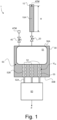
- FIG. 1 is a schematic diagram of a generator, generally designated by the numerical reference 1, according to one embodiment of the invention.
- This generator 1 notably comprises a vertical supply column 10 capable of being filled with a certain quantity of water so as to form a column of water 10A of a determined height H. It will be understood that the surface of the water column 10A is exposed to atmospheric pressure, designated ATM.
- This vertical supply column 10 is arranged above a sealed tank 30, itself filled with water, capable of being placed in communication with the vertical supply column 10 via an inlet valve 20 placed at the base of the vertical supply column 10, on the upper part 30A of the sealed tank 30.
- An exhaust valve 40 is also arranged on the sealed tank 30, which exhaust valve 40 is capable of releasing the pressure generated in the sealed tank 30 and allow the evacuation of excess water.
- This exhaust valve 40 here makes it possible to reduce the surface pressure of the liquid contained in the sealed tank 30 to atmospheric pressure ATM as well as the expulsion of excess water as will be understood on reading the description which follows.
- a piston device 50 Arranged inside the sealed tank 30 is a piston device 50 which is at least partially immersed in the water contained in the sealed tank 30.
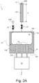
- This piston device 50 is capable of being set in reciprocating movement between a low position (see Figures 2B And 2C ) and a high position, as shown (see also Figures 2A And 2D ).
- the device forming a piston 50 comprises a first portion forming a float 51 capable of bringing the device forming a piston 50 into the high position and a second portion forming an output axis 52 emerging here in part, designated by the reference 52A, outside the sealed tank 30.
- the second portion forming an outlet axis 52 actually comprises a plurality of individual outlet axes 52, a part 52A of which emerges outside the sealed tank 30 , advantageously through a lower part 30B of the sealed tank 30.
- each outlet shaft 52 is provided with a compressible sleeve 55 ensuring sealing between the water contained in the sealed tank 30 and the part 52B of the outlet shaft 52 disposed inside the sealed tank 30.
- Each compressible cuff 55 defines a compressible volume, designated V 55 , devoid of liquid, encompassing the part 52B of the outlet axis 52 disposed inside the sealed reservoir 30.
- Other solutions could however be considered, for example example a solution adopting a single compressible cuff surrounding all of the output axes 52.
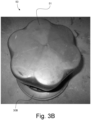
- FIGS. 3A And 3B are photographic illustrations of a prototype piston device 50, which consists of a set of seven individual output shafts 52 provided at their upper end with a flotation device, for example a block of polystyrene or any other material light and waterproof with good flotation capacity. All of the flotation devices are here arranged in the form of a compact whole and retained by an elastic sheath so as to constitute the float forming part 51 of the piston forming device 50. This part 51 moreover constitutes the head of the device forming piston 50.
- a flotation device for example a block of polystyrene or any other material light and waterproof with good flotation capacity. All of the flotation devices are here arranged in the form of a compact whole and retained by an elastic sheath so as to constitute the float forming part 51 of the piston forming device 50. This part 51 moreover constitutes the head of the device forming piston 50.
- the generator 1 further comprises a converter device 60 coupled here to the part 52A of the output axis 52 emerging outside the sealed tank 30.
- This converter device 60 can be any type of device capable of converting the reciprocating movement of the device forming a piston 50 into mechanical or electrical energy E.
- the converter device 60 can include a mechanism, as such known (such as a crankshaft type mechanism driven by connecting rods), capable of converting the reciprocating movement of the piston device 50 into a rotary movement.
- the converter device preferably comprises an alternator driven by the rotary movement in order to produce electrical energy.
- it may be a wind turbine alternator with permanent magnets, in particular permanent neodymium magnets. Tests were notably carried out by the Applicant using a Missouri Wind and Solar, LLC (www.mwands.com) brand alternator delivering approximately 12 Volts at 150 rpm.
- the vertical supply column 10 is dimensioned so as to allow the formation of a column of water 10A having a height H of the order of 50 cm to 150 cm.
- the internal diameter of the vertical supply column 10 is here preferably less than 20 cm.
- the sealed tank 30 has a capacity of around 20 to 50 liters.
- a water column of around 85 cm, an internal diameter of around 6 cm, and a sealed tank with a capacity of around 25 liters allow adequate implementation of the invention. It will be understood, however, that the invention is not specifically limited to these dimensions.
- Concerning the height H of the water column 10A this will depend in particular on the ceiling height available in the environment in which the generator according to the invention is installed.
- the generator is configured so that, in operation, the sealed tank 30 is filled with liquid, and so as to repeat the sequence of following operating phases described with reference to the Figures 2A to 2D in order to induce the reciprocating movement of the piston forming device 50.
- a first operational phase illustrated by the Figure 2A , the inlet valve 20 is closed (as is the exhaust valve 40) and the supply column 10 is filled with water so as to form a column of water 10A of determined height H. It will therefore be understood that a pressure is generated at the base of the water column 10A, the magnitude of which depends on the height H of the water column 10A.
- the inlet valve 20 is open (the exhaust valve 40 remaining closed) in order to put the vertical supply column 10 and the sealed tank 30 into communication, causing an increase in the pressure in the sealed tank 30 and causing a movement to the lower position of the device forming a piston 50.
- the increase in pressure in the sealed reservoir 30 causes the compression of the compressible cuffs 55 and a reduction in the compressible volume V 55 of each cuff 55, leading to an increase in the volume of water admitted into the sealed tank 30 and a corresponding reduction in the height, designated H*, of the column of water 10A in the vertical supply column 10.
- the cuffs 55 have in particular the advantage of offer little resistance to compression when the pressure increases in the sealed tank 30.
- a third operational phase illustrated by the Figure 2C , the inlet valve 20 is closed and the exhaust valve 40 is opened in order to release the excess pressure formed inside the sealed tank 30.
- This pressure balancing allows the piston device 50 to return to the high position under the action of the portion forming a float 51, part of the water contained in the sealed tank 30 being ejected via the exhaust valve 40 during this phase.
- the piston device 50 is thus returned to the high position under the action of the first float forming portion 51, and the process can then be repeated in order to induce an alternating movement of the piston device 50 between its high and low positions. It will be understood that additional water is added to the vertical supply column 10 in order to bring the water column 10A to the desired height H at the start of each cycle.
- the control of the inlet valve 20 and the exhaust valve 40 can be ensured by a mechanical distributor controlling the timing actuation of the valves 20, 40, it being understood that the valves 20, 40 are never opened simultaneously.
- the generator according to the invention operates at a relatively slow speed, similar to a steam engine, and it is preferable to equip this generator with a flywheel and a starter in order to ensure the initiation of operation. of the generator, the generator then being configured to maintain the rotation of the flywheel.
- the flywheel operates as an energy accumulator in mechanical form.
- the water supply to the generator 1 can in particular be ensured by means of a rainwater collection tank or a running water supply. It is also possible to use drain water delivered at the outlet of sanitary installations or any other suitable liquid.
- a certain quantity of water is “consumed” during each cycle of the generator 1.
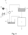
- an installation 100 as illustrated schematically in the Figure 4 comprising a collection tank 120 capable of recovering the water emanating from the sealed tank 30 of the generator 1 (in this case the water ejected via the exhaust valve 40) and returning this water into a supply tank 110 supplying the water necessary for filling the vertical supply column 10 of the generator 1.
- a pump 150 can be provided, preferably supplied with energy by means of photovoltaic panels 160 or by wind turbine 170, in order to return the water from the collection tank 120 to the supply tank 110.
- This pumping system operates in the manner of a pumped energy transfer station (or “STEP”) making it possible to exploit excess electrical energy produced by the photovoltaic panels 160 and/or the wind turbine 170 in order to pump the water collected in the collection tank 120 and return it to the supply tank 110.
- STEP pumped energy transfer station
- the pump 150 does not does not need to be operated continuously, but only periodically in order to return the collected water to the supply tank 110, therefore allowing closed circuit operation.
Description
La présente invention se rapporte de manière générale à une génératrice permettant de produire de l'énergie mécanique ou électrique à partir d'une source d'énergie renouvelable, en particulier de l'eau ou tout autre liquide (voir par exemple
Divers types de génératrices existent dans le domaine, notamment des génératrices permettant de produire de l'énergie à partir d'une source d'énergie renouvelable, en particulier hydraulique, géothermique, éolienne ou solaire. Pour une utilisation domestique, l'on fait usuellement appel à des sources d'énergie géothermique, éolienne et/ou solaire, la production d'énergie à partir d'une source d'énergie hydraulique étant usuellement réservée à des installations imposantes et complexes, tel des barrages hydroélectriques ou des installations à conduite d'eau forcée.Various types of generators exist in the field, in particular generators making it possible to produce energy from a renewable energy source, in particular hydraulic, geothermal, wind or solar. For domestic use, geothermal, wind and/or solar energy sources are usually used, with the production of energy from a hydraulic energy source usually being reserved for large and complex installations. such as hydroelectric dams or forced water installations.
Il subsiste un besoin pour des génératrices adaptées à un usage domestique exploitant de l'eau (ou autre liquide) comme source d'énergie renouvelable.There remains a need for generators suitable for domestic use using water (or other liquid) as a renewable energy source.
Un but général de la présente invention est de proposer une génératrice permettant de produire de l'énergie mécanique ou électrique à partir d'une source d'énergie renouvelable, en l'occurrence un liquide, telle l'eau.A general aim of the present invention is to propose a generator making it possible to produce mechanical or electrical energy from a renewable energy source, in this case a liquid, such as water.
Plus particulièrement, un but de la présente invention est de proposer une telle génératrice ne nécessitant pas la mise en oeuvre de moyens complexes et qui soit relativement peu coûteuse à produire.More particularly, an aim of the present invention is to propose such a generator which does not require the implementation of complex means and which is relatively inexpensive to produce.
Par ailleurs, un but de la présente invention est de proposer une telle solution qui sont particulièrement adaptée à un usage domestique.Furthermore, an aim of the present invention is to propose such a solution which are particularly suitable for domestic use.
Un autre but de la présente invention est de proposer une solution qui constitue une alternative ou un complément viable à la génération d'énergie par d'autres sources d'énergie renouvelable.Another aim of the present invention is to propose a solution which constitutes a viable alternative or complement to the generation of energy by other renewable energy sources.
Il est ainsi proposé une génératrice dont les caractéristiques sont énumérées dans la revendication 1, à savoir une génératrice comportant :
- une colonne d'alimentation verticale apte à être remplie d'une certaine quantité de liquide ;
- une vanne d'admission disposée à la base de la colonne d'alimentation verticale ;
- un réservoir étanche en communication avec la colonne d'alimentation verticale via ladite vanne d'admission, lequel réservoir étanche est apte à être rempli de liquide ;
- une vanne d'échappement disposée sur ledit réservoir étanche et apte à libérer la pression engendrée dans ledit réservoir étanche ;
- un dispositif formant piston disposé à l'intérieur dudit réservoir étanche de sorte à être immergé dans le liquide contenu dans le réservoir étanche, lequel dispositif formant piston est apte à être mis en mouvement alternatif entre une position haute et une position basse, le dispositif formant piston comportant une première portion formant flotteur apte à amener le dispositif formant piston dans la position haute et une seconde portion formant axe de sortie ; et
- un dispositif convertisseur couplé à l'axe de sortie, lequel dispositif convertisseur est apte à convertir le mouvement alternatif du dispositif formant piston en énergie mécanique ou électrique.
- a vertical supply column capable of being filled with a certain quantity of liquid;
- an inlet valve disposed at the base of the vertical supply column;
- a sealed tank in communication with the vertical supply column via said inlet valve, which sealed tank is able to be filled with liquid;
- an exhaust valve placed on said sealed tank and capable of releasing the pressure generated in said sealed tank;
- a piston device arranged inside said sealed tank so as to be immersed in the liquid contained in the sealed tank, which piston device is capable of being set in reciprocating movement between a high position and a low position, the device forming piston comprising a first portion forming a float capable of bringing the device forming a piston into the high position and a second portion forming an output axis; And
- a converter device coupled to the output shaft, which converter device is capable of converting the reciprocating movement of the piston device into mechanical or electrical energy.
La génératrice selon l'invention est configurée de sorte que, en fonctionnement, le réservoir étanche est rempli de liquide, et de sorte à répéter la séquence de phases opératoires suivantes afin d'induire le mouvement alternatif du dispositif formant piston, à savoir :
- une première phase opératoire durant laquelle la vanne d'admission est fermée et la colonne d'alimentation verticale est remplie de liquide de manière à former une colonne de liquide au-dessus du réservoir étanche ;
- une deuxième phase opératoire durant laquelle la vanne d'échappement est fermée et la vanne d'admission est ouverte afin de mettre en communication la colonne d'alimentation verticale et le réservoir étanche, engendrant une augmentation de la pression dans le réservoir étanche et causant un déplacement en position basse du dispositif formant piston ; et
- une troisième phase opératoire durant laquelle la vanne d'admission est fermée et la vanne d'échappement est ouverte afin de libérer la pression excédentaire formée à l'intérieur du réservoir étanche, permettant au dispositif formant piston de retourner en position haute sous l'action de la première portion formant flotteur.
- a first operating phase during which the inlet valve is closed and the vertical supply column is filled with liquid so as to form a column of liquid above the sealed tank;
- a second operating phase during which the exhaust valve is closed and the inlet valve is opened in order to put the vertical supply column and the sealed tank into communication, causing an increase in the pressure in the sealed tank and causing a movement to the low position of the piston device; And
- a third operating phase during which the inlet valve is closed and the exhaust valve is opened in order to release the excess pressure formed inside the sealed tank, allowing the piston device to return to the high position under the action of the first portion forming a float.
Préférablement, la seconde portion formant axe de sortie comporte une pluralité d'axes de sortie individuels. Dans ce contexte, chaque axe de sortie peut en particulier être couplé à un dispositif de flottaison qui lui est propre, les dispositifs de flottaison étant couplés les uns aux autres afin de constituer la première portion formant flotteur du dispositif formant piston.Preferably, the second portion forming an output axis comprises a plurality of individual output axes. In this context, each output axis can in particular be coupled to a flotation device of its own, the flotation devices being coupled to each other in order to constitute the first float-forming portion of the piston-forming device.
Selon une variante préférée de l'invention, chaque axe de sortie est pourvu d'une manchette compressible assurant une étanchéité entre le liquide contenu dans le réservoir étanche et une partie de l'axe de sortie disposée à l'intérieur du réservoir étanche, la manchette compressible définissant un volume compressible dépourvu de liquide englobant la partie de l'axe de sortie disposée à l'intérieur du réservoir étanche.According to a preferred variant of the invention, each outlet axis is provided with a compressible sleeve ensuring a seal between the liquid contained in the sealed tank and a part of the outlet axis disposed inside the sealed tank, the compressible cuff defining a compressible volume devoid of liquid encompassing the part of the outlet axis disposed inside the sealed tank.
La première portion formant flotteur peut avantageusement former également la tête du dispositif formant piston. Alternativement, une portion formant tête de piston pourrait être disposée au-dessus de la première portion formant flotteur.The first portion forming a float can advantageously also form the head of the device forming a piston. Alternatively, a portion forming a piston head could be placed above the first portion forming a float.
Dans une variante préférée, l'axe de sortie émerge en partie à l'extérieur du réservoir étanche et le dispositif convertisseur est couplé à la partie de l'axe de sortie émergeant à l'extérieur du réservoir étanche. Dans ce contexte, eu égard à l'utilisation de la manchette compressible susmentionnée, cette manchette compressible est préférablement interposée entre la première portion formant flotteur et une paroi intérieure du réservoir étanche. L'axe de sortie peut en particulier émerger au travers d'une partie inférieure du réservoir étanche.In a preferred variant, the output axis emerges partly outside the sealed tank and the converter device is coupled to the part of the output axis emerging outside the sealed tank. In this context, having regard to the use of the aforementioned compressible cuff, this compressible cuff is preferably interposed between the first portion forming a float and an interior wall of the sealed tank. The outlet axis can in particular emerge through a lower part of the sealed tank.
Le dispositif convertisseur peut en particulier comporter un mécanisme apte à convertir le mouvement alternatif du dispositif formant piston en un mouvement rotatif. Dans ce contexte particulier, il est outre avantageux d'équiper par ailleurs le dispositif convertisseur d'un alternateur entraîné par le mouvement rotatif afin de produire de l'énergie électrique.The converter device may in particular include a mechanism capable of converting the reciprocating movement of the piston device into a rotary movement. In this particular context, it is also advantageous to equip the converter device with an alternator driven by the rotary movement in order to produce electrical energy.
Selon une variante, la génératrice comporte en outre un dispositif de commande automatique de l'ouverture et de la fermeture des vannes d'admission et d'échappement, tel un distributeur mécanique.According to a variant, the generator further comprises a device for automatically controlling the opening and closing of the intake and exhaust valves, such as a mechanical distributor.
Selon une autre forme de réalisation, la génératrice comprend en outre un démarreur pour lancer la rotation d'un volant d'inertie couplé à la génératrice, la génératrice étant configurée afin d'entretenir la mise en rotation du volant d'inertie.According to another embodiment, the generator further comprises a starter for starting the rotation of a flywheel coupled to the generator, the generator being configured to maintain the rotation of the flywheel.
À titre préféré, la colonne d'alimentation verticale est configurée pour permettre la formation d'une colonne de liquide présentant une hauteur de l'ordre de 50 cm à 150 cm. Dans ce contexte, le diamètre de la colonne d'alimentation verticale est préférablement inférieur à 20 cm.Preferably, the vertical feed column is configured to allow the formation of a column of liquid having a height of the order of 50 cm to 150 cm. In this context, the diameter of the vertical supply column is preferably less than 20 cm.
La capacité du réservoir étanche est quant à elle préférablement de l'ordre de 20 à 50 litres, rendant la génératrice adéquate pour une utilisation domestique, des capacités plus importantes étant toutefois parfaitement envisageables.The capacity of the sealed tank is preferably of the order of 20 to 50 liters, making the generator suitable for domestic use, although larger capacities are perfectly possible.
Il est également revendiqué une installation comprenant une génératrice selon l'invention alimentée en liquide, tel que de l'eau, en particulier au moyen d'un réservoir de collecte d'eau de pluie ou d'une alimentation d'eau courante. Il serait également envisageable d'utiliser de l'eau d'évacuation délivrée en sortie d'installations sanitaires.An installation is also claimed comprising a generator according to the invention supplied with liquid, such as water, in particular by means of a rainwater collection tank or a running water supply. It would also be possible to use waste water delivered at the outlet of sanitary installations.
Dans une variante avantageuse, l'installation comporte en outre :
- un réservoir d'alimentation apte à fournir le liquide nécessaire au remplissage de la colonne d'alimentation verticale ;
- un réservoir de collecte apte à récupérer le liquide émanant du réservoir étanche ; et
- une pompe apte à retourner le liquide du réservoir de collecte au réservoir d'alimentation.
- a supply tank capable of supplying the liquid necessary for filling the vertical supply column;
- a collection tank capable of recovering the liquid emanating from the sealed tank; And
- a pump capable of returning the liquid from the collection tank to the supply tank.
La pompe susmentionnée est préférablement alimentée en énergie au moyen de panneaux photovoltaïques ou par éolienne.The aforementioned pump is preferably powered by photovoltaic panels or wind turbines.
Il est par ailleurs revendiqué un procédé de génération d'énergie mécanique ou électrique utilisant la génératrice ou l'installation selon l'invention, comportant les étapes suivantes :
- a) fermeture de la vanne d'admission et remplissage de la colonne d'alimentation verticale au moyen de liquide de manière à former une colonne de liquide au-dessus du réservoir étanche rempli de liquide ;
- b) fermeture de la vanne d'échappement et ouverture de la vanne d'admission afin de mettre en communication la colonne d'alimentation verticale et le réservoir étanche, engendrant une augmentation de la pression dans le réservoir étanche et causant un déplacement en position basse du dispositif formant piston ;
- c) fermeture de la vanne d'admission et ouverture de la vanne d'échappement afin de libérer la pression excédentaire formée à l'intérieur du réservoir étanche, permettant au dispositif formant piston de retourner en position haute sous l'action de la première portion formant flotteur ; et
- d) répétition des étapes a) à d) de sorte à induire le mouvement alternatif du dispositif formant piston et permettre au dispositif convertisseur de convertir ce mouvement alternatif en énergie mécanique ou électrique.
- a) closing the inlet valve and filling the vertical supply column with liquid so as to form a column of liquid above the sealed tank filled with liquid;
- b) closing the exhaust valve and opening the inlet valve in order to put the vertical supply column and the sealed tank into communication, causing an increase in pressure in the sealed tank and causing a movement to the low position of the piston device;
- c) closing the inlet valve and opening the exhaust valve in order to release the excess pressure formed inside the sealed tank, allowing the piston device to return to the high position under the action of the first portion forming a float; And
- d) repetition of steps a) to d) so as to induce the reciprocating movement of the piston device and allow the converter device to convert this reciprocating movement into mechanical or electrical energy.
D'autres aspects de l'invention sont exposés dans la suite de la présente description.Other aspects of the invention are explained later in this description.
Les caractéristiques et avantages de la présente invention apparaîtront plus clairement à la lecture de la description détaillée qui suit de modes de réalisation de l'invention, lesquels sont présentés uniquement à titre d'exemples non limitatifs et sont illustrés par les dessins annexés où :
- la
Figure 1 montre un diagramme schématique d'une génératrice selon un mode de réalisation de l'invention ; - les
Figure 2A-D montrent des phases opératoires successives de la génératrice de laFigure 1 ; - la
Figure 3A est une première illustration photographique d'un dispositif formant piston faisant partie de la génératrice selon un mode de réalisation de l'invention ; - la
Figure 3B est une seconde illustration photographique d'une partie supérieure du dispositif formant piston de laFigure 3A ; et - la
Figure 4 est un diagramme schématique d'une installation comprenant une génératrice selon l'invention.
- there
Figure 1 shows a schematic diagram of a generator according to one embodiment of the invention; - THE
Figure 2A-D show successive operational phases of the generator of theFigure 1 ; - there
Figure 3A is a first photographic illustration of a piston device forming part of the generator according to one embodiment of the invention; - there
Figure 3B is a second photographic illustration of an upper part of the piston device of theFigure 3A ; And - there
Figure 4 is a schematic diagram of an installation comprising a generator according to the invention.
Divers aspects de la présente invention seront décrits en référence à divers modes de réalisation préférés tels qu'illustrés notamment par les
La
À titre préféré, chaque axe de sortie 52 est pourvu d'une manchette compressible 55 assurant l'étanchéité entre l'eau contenue dans le réservoir étanche 30 et la partie 52B de l'axe de sortie 52 disposée à l'intérieur du réservoir étanche 30. Chaque manchette compressible 55 défini un volume compressible, désigné V55, dépourvu de liquide, englobant la partie 52B de l'axe de sortie 52 disposée à l'intérieur du réservoir étanche 30. D'autres solutions pourraient toutefois être envisagées, par exemple une solution adoptant une manchette compressible unique entourant l'ensemble des axes de sortie 52.Preferably, each
Les
Faisant à nouveau référence à la
Dans l'exemple illustré, la colonne d'alimentation verticale 10 est dimensionnée de manière à permettre la formation d'une colonne d'eau 10A présentant une hauteur H de l'ordre de 50 cm à 150 cm. Le diamètre interne de la colonne d'alimentation verticale 10 est ici préférablement inférieur à 20 cm. Le réservoir étanche 30 présente quant à lui une capacité de l'ordre de 20 à 50 litres. À titre illustratif, une colonne d'eau de l'ordre de 85 cm, un diamètre interne de l'ordre de 6 cm, et un réservoir étanche d'une capacité de l'ordre de 25 litres permettent une mise en oeuvre adéquate de l'invention. L'on comprendra toutefois que l'invention n'est pas spécifiquement limitée à ces dimensions. S'agissant de la hauteur H de la colonne d'eau 10A, celle-ci dépendra notamment de la hauteur sous plafond à disposition dans l'environnement dans lequel est installée la génératrice selon l'invention.In the example illustrated, the
La génératrice est configurée de sorte que, en fonctionnement, le réservoir étanche 30 est rempli de liquide, et de sorte à répéter la séquence de phases opératoires suivantes décrites en référence aux
Dans une première phase opératoire, illustrée par la
Dans une deuxième phase opératoire, illustrée par la
Dans une troisième phase opératoire, illustrée par la
Au terme de cette troisième phase opératoire, illustrée par la
La commande de la vanne d'admission 20 et de la vanne d'échappement 40 peut être assurée par un distributeur mécanique contrôlant le timing d'actionnement des vannes 20, 40, étant entendu que les vannes 20, 40 ne sont jamais ouvertes simultanément.The control of the
La génératrice selon l'invention opère à une vitesse relativement lente, similaire à une machine à vapeur, et il convient préférablement d'équiper cette génératrice d'un volant d'inertie et d'un démarreur afin d'assurer l'amorçage du fonctionnement de la génératrice, la génératrice étant alors configurée afin d'entretenir la mise en rotation du volant d'inertie. L'on comprendra alors que le volant d'inertie opère comme un accumulateur d'énergie sous forme mécanique.The generator according to the invention operates at a relatively slow speed, similar to a steam engine, and it is preferable to equip this generator with a flywheel and a starter in order to ensure the initiation of operation. of the generator, the generator then being configured to maintain the rotation of the flywheel. We will then understand that the flywheel operates as an energy accumulator in mechanical form.
L'alimentation en eau de la génératrice 1 peut notamment être assurée au moyen d'un réservoir de collecte d'eau de pluie ou d'une alimentation d'eau courante. Il est également envisageable d'utiliser de l'eau d'évacuation délivrée en sortie d'installations sanitaires ou tout autre liquide adéquat.The water supply to the
L'on comprendra qu'une certaine quantité d'eau est « consommée » lors de chaque cycle de la génératrice 1. Selon une variante avantageuse de l'invention, il est envisageable de prévoir une installation 100 telle qu'illustrée schématiquement dans la
L'on comprendra de manière générale que diverses modifications et/ou améliorations évidentes pour l'homme du métier peuvent être apportées aux modes de réalisation décrits dans la présente description sans sortir du cadre de l'invention défini par les revendications annexées.It will be generally understood that various modifications and/or improvements obvious to those skilled in the art can be made to the embodiments described in the present description without departing from the scope of the invention defined by the appended claims.
Dans une variante de l'invention, l'on pourrait par exemple envisager de disposer le dispositif convertisseur à l'intérieur du réservoir étanche, de sorte qu'il ne soit pas nécessaire que l'axe de sortie du dispositif formant piston émerge du réservoir étanche.In a variant of the invention, one could for example consider placing the converter device inside the sealed tank, so that it is not necessary for the outlet axis of the piston device to emerge from the tank. waterproof.
Par ailleurs, bien que les modes de réalisation de l'invention aient été présentés en rapport à l'utilisation d'eau comme source d'énergie renouvelable, tout autre liquide pourrait fondamentalement être utilisé.Furthermore, although the embodiments of the invention have been presented in relation to the use of water as a renewable energy source, any other liquid could basically be used.
- 11
- génératricegenerator
- 1010
- colonne d'alimentation verticalevertical power column
- 10A10A
- colonne d'eauwater column
- 2020
- vanne d'admissioninlet valve
- 3030
- réservoir étanchewaterproof tank
- 30A30A
-
partie supérieure du réservoir étanche 30upper part of the sealed
tank 30 - 30B30B
-
partie inférieure du réservoir étanche 30lower part of the sealed
tank 30 - 4040
- vanne d'échappementexhaust valve
- 5050
- dispositif formant pistonpiston device
- 5151
-
première portion (portion supérieure) formant flotteur du dispositif formant piston 50first portion (upper portion) forming a float of the
piston forming device 50 - 5252
-
seconde portion (portion inférieure) formant axe de sortie du dispositif formant piston 50 / axes de sortie individuelssecond portion (lower portion) forming output axis of the
piston device 50 / individual output axes - 52A52A
-
partie de l'axe de sortie 52 émergeant du réservoir étanche 30part of the
output axis 52 emerging from the sealedtank 30 - 52B52B
-
partie de l'axe de sortie 52 disposée à l'intérieur du réservoir étanche 30part of the
output axis 52 disposed inside the sealedtank 30 - 5555
- manchettes compressiblescompressible cuffs
- 6060
- dispositif convertisseurconverter device
- 100100
-
installation comprenant la génératrice 1
installation including generator 1 - 110110
-
réservoir d'alimentation permettant d'alimenter en eau la colonne d'alimentation verticale 10 de la génératrice 1supply tank making it possible to supply water to the
vertical supply column 10 of thegenerator 1 - 120120
-
réservoir de collecte permettant de récupérer l'eau émanant du réservoir étanche 30 de la génératrice 1collection tank making it possible to recover the water emanating from the sealed
tank 30 of thegenerator 1 - 150150
- pompepump
- 160160
- panneaux photovoltaïquesphotovoltaic panels
- 170170
- éoliennewind turbine
- HH
-
hauteur de la colonne d'eau 10A (avant ouverture de la vanne d'admission 20)height of
water column 10A (before opening of inlet valve 20) - H*H*
-
hauteur de la colonne d'eau 10A (après ouverture de la vanne d'admission 20 et mouvement du dispositif formant piston 50 en position basse)height of the
water column 10A (after opening theinlet valve 20 and movement of thepiston device 50 to the low position) - V55V55
-
volume compressible défini par la manchette compressible 55, dépourvu de liquide, englobant la partie 52B de l'axe de sortie 52 disposée à l'intérieur du réservoir étanche 30compressible volume defined by the
compressible sleeve 55, devoid of liquid, encompassing thepart 52B of theoutlet axis 52 disposed inside the sealedreservoir 30
Claims (15)
- A generator (1) comprising:- a vertical supply column (10) that can be filled with a certain quantity of liquid;- an intake valve (20) disposed at a base of the vertical supply column (10);- a leaktight tank (30) communicating with the vertical supply column (10) via said intake valve (20), which leaktight tank (30) is capable of being filled with liquid;- an exhaust valve (40) disposed on said leaktight tank (30) and capable of releasing pressure generated in said leaktight tank (30);- a piston-forming device (50) disposed inside said leaktight tank (30) so as to be immersed in the liquid contained in the leaktight tank (30), which piston-forming device (50) is capable of being set in reciprocating movement between an upper position and a lower position, the piston-forming device (50) comprising a first, float-forming portion (51) capable of bringing the piston-forming device (50) into the upper position and a second portion forming an output shaft (52); and- a converter device (60) coupled to the output shaft (52), which converter device (60) is capable of converting the reciprocating movement of the piston-forming device (50) into mechanical or electrical energy,said generator (1) being configured in such a way that, in operation, the leaktight tank (30) is filled with liquid, and in such a way as to repeat the following sequence of operating phases in order to induce the reciprocating movement of the piston-forming device (50), namely:- a first operating phase during which the intake valve (20) is closed and the vertical supply column (10) is filled with liquid so as to form a column of liquid (10A) above the leaktight tank (30);- a second operating phase during which the exhaust valve (40) is closed and the intake valve (20) is open in order to connect the vertical supply column (10) and the leaktight tank (30), generating an increase in pressure in the leaktight tank (30) and causing a displacement of the piston-forming device (50) to the lower position; and- a third operating phase during which the intake valve (20) is closed and the exhaust valve (40) is open in order to release excess pressure formed inside the leaktight tank (30), allowing the piston-forming device (50) to return to the upper position under the action of the first, float-forming portion (51).
- The generator (1) according to claim 1, wherein the second portion forming the output shaft (52) comprises a plurality of individual output shafts (52),
and wherein each individual output shaft (52) is preferably coupled to a dedicated float device, the float devices being coupled to one another in order to constitute the first, float-forming portion (51) of the piston-forming device (50). - The generator (1) according to claim 1 or 2, wherein each output shaft (52) is provided with a compressible cuff (55) ensuring sealing between the liquid contained in the leaktight tank (30) and a part (52B) of the output shaft (52) that is disposed inside the leaktight tank (30), the compressible cuff (55) defining a compressible volume (V55) devoid of liquid covering the part (52B) of the output shaft (52) that is disposed inside the leaktight tank (30).
- The generator (1) according to any one of the preceding claims, wherein the first, float-forming portion (51) also forms a head of the piston-forming device (50).
- The generator (1) according to any one of the preceding claims, wherein the output shaft (52) emerges in part (52A) outside the leaktight tank (30),
and wherein the converter device (60) is coupled to the part (52A) of the output shaft (52) emerging outside the leaktight tank (30). - The generator (1) according to claim 5, when depending on claim 3, and wherein the compressible cuff (55) is interposed between the first, float-forming portion (51) and an internal wall of the leaktight tank (30).
- The generator (1) according to claim 5 or 6, wherein the output shaft (52) emerges through a bottom part (30B) of the leaktight tank (30).
- The generator (1) according to any one of the preceding claims, wherein the converter device (60) comprises a mechanism capable of converting the reciprocating movement of the piston-forming device (50) into a rotary movement,
and wherein the converter device (60) preferably further comprises an alternator driven by the rotary movement in order to produce electrical energy. - The generator (1) according to any one of the preceding claims, further comprising a device for automatically controlling opening and closing of the intake and exhaust valves (20, 40), such as a mechanical distributor.
- The generator (1) according to any one of the preceding claims, further comprising a starter for initiating rotation of a flywheel coupled to the generator (1), the generator (1) being configured so as to maintain rotation of the flywheel.
- The generator (1) according to any one of the preceding claims, wherein the vertical supply column (10) is configured to allow formation of a column of liquid (10A) having a height (H) of the order of 50 cm to 150 cm,
and wherein the inner diameter of the vertical supply column (10) is preferably of less than 20 cm. - The generator (1) according to any one of the preceding claims, wherein the capacity of the leaktight tank (30) is of the order of 20 to 50 litres.
- An installation (100) comprising a generator (1) according to any one of the preceding claims that is supplied with liquid, such as water, in particular by means of a rainwater collection tank or a running water supply.
- The installation (100) according to claim 13, further comprising:a supply tank (110) capable of supplying the liquid necessary for filling the vertical supply column (10);a collection tank (120) capable of recovering the liquid coming from the leaktight tank (30); anda pump (150) capable of returning the liquid from the collection tank (120) to the supply tank (110),the pump being preferably supplied with energy produced by photovoltaic panels (160) or by a wind turbine (170).
- A method of generating mechanical or electrical energy using the generator (1) according to any one of claims 1 to 12 or an installation (100) according to claim 13 or 14, comprising the following steps:a) closing the intake valve (20) and filling the vertical supply column (10) with liquid so as to form a column of liquid (10A) above the leaktight tank (30) which is filled with liquid;b) closing the exhaust valve (40) and opening the intake valve (20) in order to connect the vertical supply column (10) and the leaktight tank (30), generating an increase in pressure in the leaktight tank (30) and causing a displacement of the piston-forming device (50) to the lower position;c) closing the intake valve (20) and opening the exhaust valve (40) so as to release excess pressure formed inside the leaktight tank (30), allowing the piston-forming device (50) to return to the upper position under the action of the first, float-forming portion (51); andd) repeating steps a) to d) so as to induce the reciprocating movement of the piston-forming device (50) and allow the converter device (60) to convert this reciprocating movement into mechanical or electrical energy.
Priority Applications (3)
| Application Number | Priority Date | Filing Date | Title |
|---|---|---|---|
| EP20209328.2A EP4001634B1 (en) | 2020-11-23 | 2020-11-23 | Liquid column generator |
| CA3139219A CA3139219A1 (en) | 2020-11-23 | 2021-11-16 | Liquid column generator |
| US17/532,477 US11603761B2 (en) | 2020-11-23 | 2021-11-22 | Liquid column generator |
Applications Claiming Priority (1)
| Application Number | Priority Date | Filing Date | Title |
|---|---|---|---|
| EP20209328.2A EP4001634B1 (en) | 2020-11-23 | 2020-11-23 | Liquid column generator |
Publications (3)
| Publication Number | Publication Date |
|---|---|
| EP4001634A1 EP4001634A1 (en) | 2022-05-25 |
| EP4001634C0 EP4001634C0 (en) | 2023-12-13 |
| EP4001634B1 true EP4001634B1 (en) | 2023-12-13 |
Family
ID=73544107
Family Applications (1)
| Application Number | Title | Priority Date | Filing Date |
|---|---|---|---|
| EP20209328.2A Active EP4001634B1 (en) | 2020-11-23 | 2020-11-23 | Liquid column generator |
Country Status (3)
| Country | Link |
|---|---|
| US (1) | US11603761B2 (en) |
| EP (1) | EP4001634B1 (en) |
| CA (1) | CA3139219A1 (en) |
Family Cites Families (4)
| Publication number | Priority date | Publication date | Assignee | Title |
|---|---|---|---|---|
| US4267695A (en) * | 1979-09-27 | 1981-05-19 | Peter Micciche | Buoyancy energy engine |
| KR100389064B1 (en) * | 2001-08-10 | 2003-06-25 | 김정기 | Power generation system using buoyancy and gravity |
| US20080289324A1 (en) * | 2007-05-24 | 2008-11-27 | Robert Marion | Clean energy generator |
| FI20185765A1 (en) * | 2018-09-14 | 2020-03-15 | Lsk Granit Ky | Liquid pump |
-
2020
- 2020-11-23 EP EP20209328.2A patent/EP4001634B1/en active Active
-
2021
- 2021-11-16 CA CA3139219A patent/CA3139219A1/en active Pending
- 2021-11-22 US US17/532,477 patent/US11603761B2/en active Active
Also Published As
| Publication number | Publication date |
|---|---|
| EP4001634A1 (en) | 2022-05-25 |
| CA3139219A1 (en) | 2022-05-23 |
| EP4001634C0 (en) | 2023-12-13 |
| US11603761B2 (en) | 2023-03-14 |
| US20220162942A1 (en) | 2022-05-26 |
Similar Documents
| Publication | Publication Date | Title |
|---|---|---|
| EP3303825B1 (en) | Device and method for converting and storing electric energy in the form of compressed air | |
| EP2140135B1 (en) | Device and method for collecting the kinetic energy of a naturally moving fluid | |
| US8011182B2 (en) | Vertical gravity/buoyancy power generator | |
| US20100084866A1 (en) | System and method for a hydro-hydraulic gravitational generator | |
| EP2715093A2 (en) | Device for storing and delivering fluids and method for storing and delivering a compressed gas contained in such a device | |
| GB2471538A (en) | Power generator using compressed air to turn an underwater generator | |
| FR2891095A1 (en) | INSTALLATION OF STORAGE AND RECOVERY OF ELECTRICAL ENERGY | |
| EP4001634B1 (en) | Liquid column generator | |
| CN1826463B (en) | Portable hydro-generator | |
| FR3054615A1 (en) | INSTALLATION FOR PRODUCING ELECTRICITY | |
| FR2972770A1 (en) | HYDRAULIC ENGINE ENERGY ACCUMULATOR | |
| CA2981560A1 (en) | Super graal power production system | |
| EP2392817A1 (en) | System for generating electric energy making use of water currents | |
| WO2016028133A1 (en) | Environmentally friendly power generator | |
| WO2010093267A2 (en) | System and method for the autonomous production of fluid and electricity | |
| WO2023154008A2 (en) | Improved portable hydro-generator | |
| BE1016725A6 (en) | Hydro-electric power station for use in small waterfall, has floats placed in tank fed with water for producing thrust on crankshaft at each rise of floats, for restoring or converting initial mechanical movement of corresponding float | |
| FR2757904A1 (en) | Energy converter using pressure to lift fluid charged with potential energy | |
| JP2001295747A (en) | Underwater manhole hydraulic power generating system | |
| JP2023518086A (en) | How to do work with osmosis | |
| CA2635646A1 (en) | Exploitation of seabed thermal energy | |
| FR3093168A1 (en) | MULTI-SOURCE PROGRESSIVE THERMOVOLTAIC DEVICE WITH ENERGY STORAGE CAPACITIES, AND ASSOCIATED PROCESSES. | |
| FR3097593A1 (en) | Hybrid energy storage or conversion device with liquid, gaseous or supercritical propellant | |
| CH715428A2 (en) | Power station with pulsed compressed air flow in a hermetically closed space. | |
| WO2013098494A1 (en) | Hydraulic turbine intended, in particular, for a tidal power plant |
Legal Events
| Date | Code | Title | Description |
|---|---|---|---|
| PUAI | Public reference made under article 153(3) epc to a published international application that has entered the european phase |
Free format text: ORIGINAL CODE: 0009012 |
|
| STAA | Information on the status of an ep patent application or granted ep patent |
Free format text: STATUS: THE APPLICATION HAS BEEN PUBLISHED |
|
| AK | Designated contracting states |
Kind code of ref document: A1 Designated state(s): AL AT BE BG CH CY CZ DE DK EE ES FI FR GB GR HR HU IE IS IT LI LT LU LV MC MK MT NL NO PL PT RO RS SE SI SK SM TR |
|
| STAA | Information on the status of an ep patent application or granted ep patent |
Free format text: STATUS: REQUEST FOR EXAMINATION WAS MADE |
|
| 17P | Request for examination filed |
Effective date: 20221115 |
|
| RBV | Designated contracting states (corrected) |
Designated state(s): AL AT BE BG CH CY CZ DE DK EE ES FI FR GB GR HR HU IE IS IT LI LT LU LV MC MK MT NL NO PL PT RO RS SE SI SK SM TR |
|
| GRAP | Despatch of communication of intention to grant a patent |
Free format text: ORIGINAL CODE: EPIDOSNIGR1 |
|
| STAA | Information on the status of an ep patent application or granted ep patent |
Free format text: STATUS: GRANT OF PATENT IS INTENDED |
|
| INTG | Intention to grant announced |
Effective date: 20230112 |
|
| GRAJ | Information related to disapproval of communication of intention to grant by the applicant or resumption of examination proceedings by the epo deleted |
Free format text: ORIGINAL CODE: EPIDOSDIGR1 |
|
| STAA | Information on the status of an ep patent application or granted ep patent |
Free format text: STATUS: REQUEST FOR EXAMINATION WAS MADE |
|
| GRAP | Despatch of communication of intention to grant a patent |
Free format text: ORIGINAL CODE: EPIDOSNIGR1 |
|
| STAA | Information on the status of an ep patent application or granted ep patent |
Free format text: STATUS: GRANT OF PATENT IS INTENDED |
|
| INTC | Intention to grant announced (deleted) | ||
| INTG | Intention to grant announced |
Effective date: 20230627 |
|
| GRAS | Grant fee paid |
Free format text: ORIGINAL CODE: EPIDOSNIGR3 |
|
| GRAA | (expected) grant |
Free format text: ORIGINAL CODE: 0009210 |
|
| STAA | Information on the status of an ep patent application or granted ep patent |
Free format text: STATUS: THE PATENT HAS BEEN GRANTED |
|
| AK | Designated contracting states |
Kind code of ref document: B1 Designated state(s): AL AT BE BG CH CY CZ DE DK EE ES FI FR GB GR HR HU IE IS IT LI LT LU LV MC MK MT NL NO PL PT RO RS SE SI SK SM TR |
|
| REG | Reference to a national code |
Ref country code: GB Ref legal event code: FG4D Free format text: NOT ENGLISH |
|
| REG | Reference to a national code |
Ref country code: CH Ref legal event code: EP |
|
| REG | Reference to a national code |
Ref country code: DE Ref legal event code: R096 Ref document number: 602020022628 Country of ref document: DE |
|
| REG | Reference to a national code |
Ref country code: IE Ref legal event code: FG4D Free format text: LANGUAGE OF EP DOCUMENT: FRENCH |
|
| REG | Reference to a national code |
Ref country code: CH Ref legal event code: PK Free format text: RECTIFICATIONS |
|
| U01 | Request for unitary effect filed |
Effective date: 20240105 |
|
| U07 | Unitary effect registered |
Designated state(s): AT BE BG DE DK EE FI FR IT LT LU LV MT NL PT SE SI Effective date: 20240117 |
|
| PG25 | Lapsed in a contracting state [announced via postgrant information from national office to epo] |
Ref country code: GR Free format text: LAPSE BECAUSE OF FAILURE TO SUBMIT A TRANSLATION OF THE DESCRIPTION OR TO PAY THE FEE WITHIN THE PRESCRIBED TIME-LIMIT Effective date: 20240314 |
|
| PG25 | Lapsed in a contracting state [announced via postgrant information from national office to epo] |
Ref country code: ES Free format text: LAPSE BECAUSE OF FAILURE TO SUBMIT A TRANSLATION OF THE DESCRIPTION OR TO PAY THE FEE WITHIN THE PRESCRIBED TIME-LIMIT Effective date: 20231213 |
|
| PG25 | Lapsed in a contracting state [announced via postgrant information from national office to epo] |
Ref country code: GR Free format text: LAPSE BECAUSE OF FAILURE TO SUBMIT A TRANSLATION OF THE DESCRIPTION OR TO PAY THE FEE WITHIN THE PRESCRIBED TIME-LIMIT Effective date: 20240314 Ref country code: ES Free format text: LAPSE BECAUSE OF FAILURE TO SUBMIT A TRANSLATION OF THE DESCRIPTION OR TO PAY THE FEE WITHIN THE PRESCRIBED TIME-LIMIT Effective date: 20231213 |