EP4001508A1 - Device and method for sand blasting - Google Patents
Device and method for sand blasting Download PDFInfo
- Publication number
- EP4001508A1 EP4001508A1 EP21185854.3A EP21185854A EP4001508A1 EP 4001508 A1 EP4001508 A1 EP 4001508A1 EP 21185854 A EP21185854 A EP 21185854A EP 4001508 A1 EP4001508 A1 EP 4001508A1
- Authority
- EP
- European Patent Office
- Prior art keywords
- sand
- chassis
- cleaning device
- elevator
- arm
- Prior art date
- Legal status (The legal status is an assumption and is not a legal conclusion. Google has not performed a legal analysis and makes no representation as to the accuracy of the status listed.)
- Withdrawn
Links
Images


Classifications
-
- E—FIXED CONSTRUCTIONS
- E01—CONSTRUCTION OF ROADS, RAILWAYS, OR BRIDGES
- E01H—STREET CLEANING; CLEANING OF PERMANENT WAYS; CLEANING BEACHES; DISPERSING OR PREVENTING FOG IN GENERAL CLEANING STREET OR RAILWAY FURNITURE OR TUNNEL WALLS
- E01H12/00—Cleaning beaches or sandboxes
- E01H12/008—Cleaning beaches or sandboxes cleaning sandboxes
Definitions
- the present invention relates to an apparatus and a method for cleaning sand.
- Sand here means granular, mineral materials made in particular from quartz, lime, dolomite or granite, with a typical grain size of about 1 to 6 mm.
- Ceramic specifically includes the loosening, aeration and removal of contaminants by raising the sand above its surface and passing it through a screen which separates out the contaminants.
- Typical uses of the invention relate to the cleaning of sand on sandpits and fall protection areas below play and climbing equipment, as well as the sand on diving pits and shot put facilities in schools and sports facilities, and sand on beaches and leisure facilities.
- Sand cleaning on playgrounds and sports and leisure facilities is carried out to a large extent by specialized commercial companies commissioned by municipalities such as cities and municipalities.
- Animal excrement, broken glass, bottle caps, cigarette butts and the like are typically found in the surface layers of soiled sand. Up to a distance of about 15 to 20 cm from the sand surface, aerobic microflora predominate. Depending on the type, quality and compaction of the sand, this is followed by anaerobic microflora at a depth of about 25 to 40 cm, whose bacteria and microorganisms cause the typical moldy smell that can occur on sandy surfaces that have not been cared for for a long time.
- the sand must also be regularly loosened to a depth of at least 40 cm on the fall protection areas below play and climbing equipment in order to ensure effective fall protection.
- Proper and high-quality sand cleaning requires not only the detection of the cleaned area, but also the detection and recording of the working depth.
- the sand elevator was built according to the state of the art (EP 1 108 816 A2 ) provided with a plurality of sand conveying elements (slats, shovels, buckets) attached to a motor-driven, endless conveyor (chains or belts arranged parallel and spaced apart from one another, or a single, wide, circulating belt of rubber material) which are arranged between a, in the digging position that can be immersed in the sand to be cleaned and a discharge position, preferably conveying overhead, from which the sand raised with the aid of the sand conveying elements is thrown onto a sieve that lets the sand pass and separates impurities that get into the receiving container.
- sand conveying elements slats, shovels, buckets
- a motor-driven, endless conveyor chains or belts arranged parallel and spaced apart from one another, or a single, wide, circulating belt of rubber material
- the screen can be an inclined vibrating screen, and the sand that has passed the screen automatically falls back onto the sand surface behind the pick-up point.
- the frame (chassis) running on wheels, caterpillars and/or chains is typically equipped with at least one motor-driven shaft in order to create a mobile, self-propelled sand cleaning device.
- the engine located on the chassis typically an internal combustion engine, is expediently coupled to a hydraulic pump, which supplies the various consumers (travel drive, conveying device of the sand elevator) with hydraulic fluid via hydraulic lines.
- at least the sand elevator is typically provided with a covering and housing.
- Gram Culture means - depending on the adjustment/lowering of the sand elevator - that section of the conveying device with conveying elements that is in the to be cleaned sand is immersed so that the moving conveying elements dig into the sand and absorb sand.
- “Dig position” refers to such a position of the conveying device in which the digging piece dips into the sand to be cleaned.
- “Dig depth” means, within the sand to be cleaned, the distance between the middle sand surface and the lower edge of the lowermost conveying element when the digging piece assumes its digging position.
- the massive, heavy frame of the sand cleaning device can serve as a reference point for the sand surface when it is standing or driving on the sand surface.
- the sand elevator uses a digging piece that can be adjusted between a selectable working position (digging position) dipping into the sand to different depths and a resting position above the sand surface.
- the digging piece assumes this resting position, for example, when the mobile sand cleaning device drives automatically from its transport vehicle to the place of use, or when the sand cleaning device is reset in the course of the sand cleaning. Starting from this resting position, the digging piece must be lowered until it dips deep enough into the sand to be cleaned so that the sand elevator can pick up and circulate sand.
- Such lowering of the grave piece is achieved by adjusting the sand elevator with respect to a frame (chassis) of the sand cleaning device which holds the sand elevator.
- the entire sand elevator can be articulated pivotably on the chassis.
- the pivoting is effected by a hydraulically operated piston/cylinder arrangement, the piston rod of which adjusts the sand elevator in such a way that its digging piece dips more or less deeply into the sand.
- the entire sand elevator can be along two, parallel and spaced from each other as well as almost vertically aligned rails that are permanently attached to the chassis (downwards) onto the sand surface or away from the sand surface (upwards).
- the downward adjustment (lowering) typically occurs solely under the action of gravity.
- At least one hydraulically operated piston/cylinder arrangement which is inserted between a carrier on the chassis and an abutment on the sand elevator, ensures the upward adjustment (raising).
- Known mobile sand cleaning devices of this kind are in use and for example in the documents DE-C2-32 09 134 , DE-C2-34 37 926 , DE-A1-35 13 454 , DE-A1-40 07 409 or in the German patent application 198 53 351.9 described.
- the digging depth is determined solely and exclusively by the appropriate setting and locking of levers, rods or lifting cylinders, which fix the sand elevator in a specific position with respect to the chassis, so that the digging piece can be moved up to a specific dig depth in accordance with this sand elevator position immersed in the sand to be cleaned.
- the document EP 0 319 420 B1 discloses a self-propelled machine for cleaning beaches.
- the known self-propelled device has a tipping container into which the collected waste is conveyed. Also forward of the machine is a pivoted conveyor terminating at its inlet in a scraper plate which slides across the beach to be cleaned to collect debris which is then conveyed into the tipping bin by the two-stage conveyor.
- the document DE 36 27 015 A1 discloses an earth clearing device, for example in the form of a bucket wheel excavator, with a chassis on which there is an elevator whose inclination relative to the chassis can be changed.
- An adjusting cylinder is used to change the elevator inclination a sensor is assigned, which detects the respective elevator inclination and converts it into electrical signals which are fed to a signal processing device.
- the technical field of the present invention lies in specifying or providing a device for, in particular, commercial sand cleaning.
- This prior art also describes a mobile sand cleaning device with a frame that can be moved on the original surface of the sand layer to be cleaned and on which a sand elevator is mounted adjustable, in particular lowerable and raisable, which is equipped with an endless belt, motor-driven, circulating conveying device which is provided with a large number of conveying elements which circulate between a digging position immersed in the sand to be cleaned and a discharge position from which the sand transported in the conveying elements is thrown onto a sieve located on the sand cleaning device, which allows the sand to pass and separates impurities that end up in a collecting tank, the respective digging depth depending on the extent of the respective adjustment/lowering of the sand elevator with respect to the frame, wherein the sand cleaning device is equipped with a device for recording electrical signals, for processing these signals into data and for storing, making available and/or making these data available; and there is also a sensor which detects the respective adjustment/lowering of the sand elevator with respect to the frame and generate
- this object is achieved with a device according to claim 1 or 11, which for the first time allows cleaning very small, very narrow or very narrow sandy areas, which can also be surrounded by a raised border, as well as working under trees and under playground equipment .
- a sand cleaning device which comprises a chassis and a sand elevator which is held on the chassis in an adjustable manner, in particular such that it can be lowered and raised, and is equipped with a motor-driven, revolving conveying device which is provided with a large number of conveying elements which circulate between a digging position immersed in the sand to be cleaned and a dumping position from which the sand transported in the conveying elements is thrown onto a sieve which allows the sand to pass and which separates impurities which reach a collection container, the conveying device is cylindrical, its axis of rotation runs parallel to the surface of the sand to be cleaned, its end faces and lateral surface are closed, and the conveying elements are attached to the lateral surface of the conveying device. This builds the conveyor much flatter and can also be used under obstacles such as trees or playground equipment.
- conveying elements are removably attached to the lateral surface of the conveying device.
- conveying elements damaged by heavy foreign objects in the sand can be replaced quickly and easily without having to replace the entire conveying device.
- the sand elevator is connected to the chassis by means of an arm, the arm comprising two members which are pivotally connected to one another about an axis parallel to the sand surface, the member facing the chassis being pivotable about an axis parallel to the sand surface is pivoted to the chassis.
- the arm comprising two members which are pivotally connected to one another about an axis parallel to the sand surface, the member facing the chassis being pivotable about an axis parallel to the sand surface is pivoted to the chassis.
- the sand elevator is pivoted about an axis parallel to the surface of the sand at the free end of the limb of the arm facing away from the chassis. In this way, the change in the working position of the sand elevator when the arm is extended and retracted can be easily compensated. This improves the efficiency of the sand elevator in the far extended or far retracted position.
- the sand elevator can be moved back and forth on a rail which runs radially away from the chassis about an axis parallel to the surface of the sand and is pivotably articulated at the free end of the member of the arm facing away from the chassis. In this way, the reciprocation of the sand elevator for sand cleaning can be performed without complicated movements of the arm, whereby the Operation of the sand cleaning device according to the invention is greatly facilitated.
- Hydraulic cylinders are preferably used to pivot the links.
- the sand elevator can also be moved back and forth on the rail by means of a hydraulic cylinder or an electric motor.
- the conveyor elements are preferably designed as angular strips with two legs, one leg of which is screwed to the lateral surface of the conveyor device and the other leg of which is beveled in the direction of rotation of the conveyor device.
- the conveying elements are preferably closed on the side by a metal sheet. This prevents sand losses to the side during the conveying process.
- the rail on which the sand elevator is reciprocally movable can preferably be provided with a coupling for coupling an arm of a commercially available excavator.
- the sand cleaning device according to the invention then does not require its own chassis with hydraulic arm, but can be coupled to any commercially available excavator (as well as excavator shovels of different sizes and other tools). Recently, a hydraulic coupling has also been made available, so that the hydraulic pressure required to drive the conveying device can be made available by the commercially available excavator.
- the above object is also provided with a mobile sand cleaning device with a chassis on which a sand elevator is adjustable, in particular lowerable and raisable, which is equipped with an endless, motor-driven, circulating conveying device, which is provided with a large number of conveying elements, which circulate between a digging position immersed in the sand to be cleaned and a discharge position, from which the The sand transported by the conveying elements is thrown onto a sieve located on the sand cleaning device, which allows the sand to pass and separates impurities which end up in a collection container, the sand elevator being connected to the chassis by means of a telescopically retractable and extendable arm.
- the arm is horizontally rotatably attached to the chassis. This eliminates the need to rotate the carriage itself by means of the crawler tracks or wheels on the carriage, which may cause damage to the sand cleaning apparatus stand.
- the arm is vertically pivotably attached to the chassis. This also makes it possible to work over an enclosure in the path.
- chassis runs on crawler tracks. This significantly improves the off-road mobility of the mobile sand cleaning device.
- the sand elevator is attached to the distal end of the arm such that it can rotate about an axis perpendicular to the direction of extension of the arm. In this way, the working direction of the sand elevator can be flexibly adapted to the shape of the sand area to be cleaned.
- the sand elevator is arranged at the distal end of the arm so that it can be lowered perpendicular to the direction in which the arm extends. In this way it is possible to reach and clean a sandy area below, even over relatively high enclosures.
- This advantage can also be achieved in that the arm is mounted so that it can pivot vertically about a bearing block, and the bearing block can be raised vertically upwards and lowered downwards relative to the chassis.
- the revolving conveying device is formed by a wheel rotating about a horizontal axis, on the radial outside of which the conveying elements are arranged.
- the construction of the conveying device is as light and small as possible, which facilitates the handling of the sand elevator by the telescopic arm. It is then not so strong telescopic arm required.
- the circulating conveying device is designed as a hollow cylinder with a horizontal axis of rotation, on whose lateral surface the conveying elements are arranged.
- the object of the invention is also achieved by a method for cleaning sand, in particular for cleaning sand in sandpits, playgrounds and sports facilities, in which a mobile sand cleaning device having a chassis on which a sand elevator is adjustable, in particular lowerable and raisable, is held which is equipped with an endless circulating conveyor which is provided with a plurality of conveying elements which circulate between a digging position immersed in the sand to be cleaned and a dumping position from which the sand transported in the conveying elements is thrown onto a sieve located on the sand cleaning device , which allows the sand to pass and which separates impurities that are collected in a Arrive collection container, wherein the sand elevator is lowered into the sand to be cleaned and moved in the sand to be cleaned by means of a telescopically retractable and extendable, rotatably and pivotably mounted arm on the chassis.
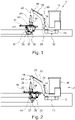
- a sand cleaning device 1 comprises a chassis 10 which is provided with crawler tracks 12 .
- the chassis 10 can of course also be provided with pneumatic tires.
- a frame 14 is rotatably mounted about a vertical axis.
- This frame 14 carries a driver's cab 16 and on this frame 14 is a swivel arm 18 about an axis parallel to the sand surface to be processed, ie horizontally, pivotably mounted.
- the pivot arm 18 includes a proximal and a distal member 20, 22, the are also hinged to one another so as to be pivotable about a horizontal axis, that is to say running parallel to the surface to be machined.
- the proximal member 20 is pivoted by a hydraulic cylinder 24 . This is mounted on the frame 14.
- the distal member 22 is pivoted by a hydraulic cylinder 26 articulated to the proximal member 20 .
- an adapter 28 which can be pivoted about a horizontal axis and which is also articulated on the distal end so that it can be pivoted about a horizontal axis.
- This adapter 28 is pivoted by a further hydraulic cylinder 30.
- the device described corresponds to a commercially available small excavator, which is usually also equipped with adapters 28 for receiving various tools such as excavator shovels, grippers, etc.
- These small excavators are preferably also provided with a tap connection for the hydraulic fluid, so that the devices attached to the adapter, such as grabs or the sand elevator 36 according to the invention, are powered by the power source of the excavator, which is usually a hydraulic pump arranged on the frame 14 or under the driver's cab 16 , can be driven.
- the power source of the excavator which is usually a hydraulic pump arranged on the frame 14 or under the driver's cab 16 , can be driven.
- the sand elevator 36 of the present invention preferably includes a suitable receptacle 32 for the adapter 28 so that the sand elevator 36 of the present invention can be connected to a commercially available excavator in lieu of any other tool.
- the receiving element 32 for the adapter 28 is preferably not connected directly to the sand elevator 36, but is arranged on a rail 34 running horizontally.
- the receiving element 32 for the adapter 28 and the sand elevator 36 can each be moved back and forth along the rail 34, so that it is possible to work on a sandbox by simply moving the rail 34 opposite the receiving element 32 for the adapter 28 and the sand elevator 36 opposite the rail 34 and is moved. In this way, a uniform digging depth is ensured without the need for complicated control of the swivel arm 18 in order to move the sand elevator 36 away from and back onto the chassis 10 with a constant digging depth.
- the sand cleaning device according to the invention can for the first time also be used in sand areas, for example sand boxes, which are surrounded by an enclosure.
- the sand elevator 36 comprises a conveying device 37 enclosed by a housing 38 .
- this housing 38 has two end-face end plates 40 on both sides of the conveying device 37, which have the shape of a sector of a circle in the distal area and are rectangularly terminated proximally.
- a lateral surface 42 of the housing 38 is formed by a correspondingly bent metal sheet, which then ends straight to the rear. Further details of the sand elevator 36 are described below.
- the 1 shows the sand elevator 36 in a middle working position.
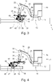
- the 2 shows the same arrangement as 1 , but with the sand elevator 36 fully retracted towards the chassis 10.
- FIG 3 shows a further embodiment of the sand cleaning device 1 according to the invention, in which the sand elevator 36 is provided with its own chassis 44, which consists of two pneumatic tires 46 arranged distally in front of the sand elevator 36. These pneumatic tires 46 are preferably also arranged next to the sand elevator 36 in the width direction, so that the track width of the two pneumatic tires 46 is wider than the width of the sand elevator 36.
- This chassis 44 is used on the one hand to prevent the tilting moment, which acts on the chassis 10, from becoming too large when the sand elevator 36 is in the distally fully extended position, by the two pneumatic tires 46 then having the corresponding moment compared to the support the ground.
- the two pneumatic tires 46 are adjustable in height, and by adjusting the height of the chassis 44, the digging depth of the sand elevator 36 can be precisely set and maintained.
- FIG 3 shows a middle position of the adapter 28 and a maximally proximal retracted position of the sand elevator 36.
- the sieve 48 and collecting container 50 are firmly connected to the housing 38 of the sand elevator 36, so that optimal sand cleaning is guaranteed despite different working positions.
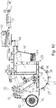
- figure 5 shows the swivel arm 18 in the maximum extended position, with the adapter 28 in turn being in the middle position and the sand elevator 36 also being extended to the maximum.
- FIG. 6 also shows the swivel arm 18 and the sand elevator 36 which are extended to the maximum, whereby this time the adapter 28 is also extended to the maximum, ie it is in a rear position in the vicinity of the chassis 10 (proximal).
- FIG. 7 shows only the device consisting of adapter 32, rail 34 and sand elevator 36, which is to be fastened to the swivel arm 18 with the adapter 32, obliquely from above in a three-dimensional representation in order to show the technical details of the device more clearly.
- the adapter 32 can be moved along the rail 34 by means of a hydraulic cylinder 52 .
- Another hydraulic cylinder 54 engages the outer surface 42 of the sand elevator housing 38 and enables the sand elevator housing 38 to be moved back and forth with respect to the rail 34 .
- a carriage 56 with rollers 58 is movably mounted in the rail 34 .
- the sand elevator 36 comprises a sheet metal construction in the form of a cylindrical drum as the conveying device 37, the axis of rotation of which runs parallel to the surface of the sand to be processed. Evenly spaced conveying elements 76 are screwed to the outer surface of the drum, projecting radially outwards.
- These conveying elements 76 comprise an L-profile with two legs at an angle of about 90° to one another, the shorter legs of which are parallel to the Lateral surface 42 of the conveying device 37 is arranged, while the other longer leg projects radially from the lateral surface 42 and is bent in its outer area counter to the intended direction of rotation of the conveying device 37 .
- the conveying elements 76 are closed off by a pentagonal plate 78 so that sand caught by the conveying elements 76 can no longer flow off to the side.
- the housing 38 supports the running gear 44, which includes a shaft 80 which supports the two tires 46 in a rotatable manner, the distance between the tires 46 being greater than the width of the housing 38 and the shaft 80 being horizontal to the surface of the sand to be processed runs.
- the shaft 80 is designed to be adjustable in height, in that a piece of pipe 82 is attached in the middle of the shaft 80, which is accommodated in a further piece of pipe 84 with a larger inside diameter than the outside diameter of the piece of pipe 82, with the piece of pipe 84 on the Front of the housing 38 is fixed and mounted vertically.
- the height of the chassis 44 and thus the digging depth of the sand elevator 36 can thus be adjusted by adjusting the height of the chassis 44 by adjusting the pipe section 82 in the pipe section 84 .
- the pipe section 82 can then be mechanically fixed in the pipe section 84, for example by means of a locking screw 86.
- the pipe sections 82, 84 are polygonal, preferably rectangular or square in cross section.
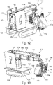
- FIG. 8 shows the sand elevator 36 according to the invention from the outside, ie viewed in the direction of the chassis 10 .
- the design and the screwing of the conveying elements 76 become even clearer in that the screw heads 88 are visible.
- stabilizing plates 90 arranged further inwards parallel to the plates 78 can be seen same shape as the plates 78, which serve the outer end of the conveyor elements 76 correspond.
- the hydraulic motor 92 arranged on the outside of the lateral surface 42 can also be seen, which drives the conveying device 37 via a belt pulley 94 and drive belt 96 .
- FIG 9 shows the sand cleaning device of FIG 7 of the page.
- the hydraulic motor 92, the belt pulley 94 and the drive belt 96 for driving the conveying device 37 can be clearly seen.
- the pulley 98 can be seen here, which sits on a common shaft with the conveyor 37 and is driven by the drive belt 96 .
- the figures 7 , 8th and 9 show both the receiving element 32 and the sand elevator 36 in a middle position on the rail 34.
- FIG. 1 shows the sand elevator 36 fully extended in the distal direction, while the receiving element 32 is still positioned in the middle position.
- 11 12 shows the sand elevator 36 in the fully proximally retracted position on the rail 34, i.e. in the position closest to the carriage 10.
- the conveyor 37 rotates clockwise, ie so that the conveyor elements 76 are moved down to the front.
- the conveying elements 76 are filled with the sand in which the conveyor 37 is immersed. This is conveyed upwards on the distal side of the housing 38 and cannot escape laterally from the conveying elements 76 through the metal sheets 78 .
- the sand is then ejected backwards through the opening of the housing 38 between the end plates 40 by centrifugal force and gravity and hits the catch sieve 48.
- This can have a suitable mesh diameter so that only sand components of a suitable fineness can pass through pass through the catch screen 48 and be deposited back on the ground.
- Catching sieve 48 and collection container 50 preferably consist of metal grids with a corresponding mesh size. Catching sieve 48 and collecting container 50 can be provided with a vibrating device so that the sand falls through better.
- impeller elements 76 be damaged by particularly large or heavy foreign objects in the sand, the operator can easily replace them by unscrewing the three screws 88, removing the damaged impeller element 76 and screwing on a new impeller element 76 without having to leave the machine for a long time fails.
- FIG. 12 shows a further sand cleaning device 110 according to the invention in a 3-dimensional representation from diagonally behind in the transport position, i.e. with the telescopic arm 130 fully retracted.
- the further sand cleaning device 110 comprises a chassis 120, which is preferably provided with crawler tracks 122 for independent locomotion of the machine.
- wheels preferably with pneumatic tires, can also be provided on the chassis 120 instead.
- a telescopic arm 130 is mounted on the chassis 120 so that it can rotate horizontally relative to the chassis 120 .
- the telescopic arm 130 can be moved in and out by means of a multi-stage hydraulic cylinder 132 .
- the telescopic arm 130 is mounted on a platform 150 so that it can pivot about a horizontal axis.
- at least one hydraulic cylinder 136 is provided, which acts between the telescopic arm 130 and the platform 150 .
- a hydraulic cylinder 136 is preferably provided on both sides of the telescopic arm 130 in order to better distribute the forces that arise.
- the platform 150 can be moved up and down in the vertical direction on four vertical rails 152 .
- the rails 152 are preferably arranged on both sides of the platform 150 and in each case at the front and rear, so that there is a corresponding rail at each corner of the platform 150 .
- a vertically acting hydraulic cylinder 154 Preferably on the side of the platform 150 opposite the telescopic arm, there is a vertically acting hydraulic cylinder 154, optionally multi-stage, which is used to raise and lower the platform 150.
- the hydraulic cylinder 154 is thus arranged between the platform 150 and one horizontally rotatable part 124 of the chassis 120 .
- the sand elevator 140 is attached to the distal end of the telescopic arm 130 so that it can rotate about a vertical axis.
- the sand elevator 140 can also be lowered and raised from the distal end of the telescopic arm 130 by means of hydraulic cylinders or by means of a toothed rack.
- a corresponding lowering option for the Sandelevator 140 allows even better work beyond the enclosures of sand courts.
- the sand elevator 140 itself comprises a conveying device 170, which is designed in the form of a mill wheel or a hollow cylinder, on the outer surface of which conveying elements 176 are arranged.
- the conveyor device 170 rotates about the axis of rotation of the hollow cylinder, which runs essentially horizontally.
- the conveyor elements 176 are designed as essentially rectangular plates that are slightly concave in the direction of rotation of the conveyor device 170 and have a front edge that projects in the direction of rotation and runs parallel to the axis of rotation of the hollow cylinder.
- the edges of the hollow cylinder are formed by circumferential rings that connect the individual conveying elements 176.
- a protective plate 172 is mounted forward in the direction of rotation of the conveyor device 170 and is in the form of a quarter sector of a hollow cylinder coaxial with the hollow cylinder of the conveyor device 170 with a slightly larger diameter and slightly longer length than the hollow cylinder of the conveyor device 170 .
- This protective plate prevents the sand picked up by the conveying elements 176 from being thrown forward by the centrifugal force. Rather, the guard plate 172 forces the sand to remain on the conveyor elements 176 until it has passed the highest point of the conveyor 170.
- the protective plate 172 in the form of a hollow cylinder sector merges into a cuboid box 174 with the same cross section.
- the sand leaves the blades of the conveying elements 176 and flies out of the box 174 to the rear. After leaving the box 174, the sand hits a sieve 180 arranged behind it, which pushes the box 174 in the direction of flight of the sand essentially closed.
- the sieve 180 also has a rectangular shape, like the cross-section of the box 174, but has slightly larger dimensions in order to still be able to sieve sand that has been deflected to the side.
- the sand passes through the sieve 180 and the impurities are held back by the sieve 180 and fall down along the almost vertical sieve 180 into a cuboid collecting container 183 which is arranged horizontally parallel to the axis of rotation of the conveying device and is approximately as wide as the sieve 180, but has a significantly shorter length.
- the impurities that have been screened out collect in the collecting container 183, the collecting container 183 can be removed in order to empty it if necessary.
- at least the side surfaces of the collecting container 183 like the sieve 180, are designed as a fine metal mesh which does not significantly impede the passage of the sand, but retains all larger contaminants.
- the screen 180 may be slanted slightly so that its top edge is slightly further away (backward) from the conveyor. This further facilitates the passage of the sand.
- the front and rear directions are considered to be in the working direction with respect to the sand elevator 140, i.e. the screen 180 on which the screened sand is ejected is defined as rear.
- the conveying elements 176 then move downwards, i.e. on the side facing the sand or immersed in the sand, forwards at the front within the protective plate 172 and downwards at the rear, while the sand picked up is thrown through the sieve 180 by centrifugal force.
- the conveying device 170 is driven by an electric or hydraulic motor 190 which is located directly above the axis of rotation of the conveying device and directly outside the protective plate 172 .
- the axis of rotation of the motor is parallel to the axis of rotation of the conveying device if a V-belt drive preferably takes place via a pulley 192 attached to the motor shaft, a V-belt 193 and another pulley 194 attached to the conveying device.
- a chain drive, a drive via a shaft with two bevel gears and similar drive solutions are of course also possible.
- the advantage of the motor arrangement described here is that the motor is optimally protected against damage.
- the sand cleaning device 110 moves on its crawler tracks 122 close to the wall, the telescopic arm is pivoted upwards via the hydraulic cylinder 136 and extended via the multi-stage hydraulic cylinder 132. As soon as the sand elevator 140 is beyond the wall, it is lowered again and can then be moved back and forth in the sand to be cleaned by swiveling the telescopic arm 130 sideways and by extending and retracting the telescopic arm 130 laterally to its working direction, such as this in figure 14 is shown as an example.
- the sand elevator can also be used as in figure 15 be used.
- the sand elevator is aligned in the direction of the telescopic arm 130, i.e. the axis of rotation of the conveying device 170 is perpendicular to the direction of extension of the telescopic arm.
- the sand elevator 140 can then be moved back and forth by extending and retracting the telescopic arm 130 and can only be moved by turning the rotatable one to the side Clean part 124 or the entire sand cleaning device 110 lane by lane the sand.
- a further electric or hydraulic motor can be provided at the distal end of the telescopic arm 130.
- the sand cleaning device 110 has the great advantage that it can also be used to perfectly clean small sand areas that are difficult to access, for example those located beyond an enclosure. For the first time, the cleaning of sandy areas without direct access is also possible. Not all previously described degrees of freedom of movement possibilities of the sand cleaning device have to be realized.
- the part 124 can also be firmly connected to the chassis 120 .
- the required rotation of the sand cleaning device then takes place via the crawler tracks 122 or correspondingly provided wheels.
- the ability to lower and/or actively rotate the sand elevator 140 relative to the distal end of the telescopic arm 130 can be dispensed with.
- the sand elevator 140 can, for example, also be rotated in the appropriate direction by the operator before the start of work and then fixed to the distal end of the telescopic arm.
- the ability to move the platform 150 up and down can also be dispensed with, for example if work does not have to be carried out over high enclosures.
Abstract
Sandreinigungsvorrichtung (10) mit einem Fahrgestell (20), an dem ein Sandelevator (40) verstellbar, insbesondere absenkbar und anhebbar gehalten ist, der mit einer endlosen, motorisch antreibbaren, umlaufenden Fördereinrichtung (70) ausgerüstet ist,die mit einer Vielzahl Förderelemente (76) versehen ist, die zwischen einer in den zu reinigenden Sand eintauchenden Grabstellung und einer Abwurfstellung umlaufen, aus welcher der in den Förderelementen (76) transportierte Sand auf ein an der Sandreinigungsvorrichtung befindliches Sieb (80) geworfen wird, das den Sand passieren lässt und das Verunreinigungen abtrennt, die in einen Auffangbehälter (83) gelangen, wobei der Sandelevator (40) mittels eines ein- und ausfahrbaren Armes (30) mit dem Fahrgestell (20) verbunden ist, und Verfahren zur Sandreinigung mit dieser Vorrichtung.Sand cleaning device (10) with a chassis (20) on which a sand elevator (40) is held in an adjustable manner, in particular such that it can be lowered and raised, which is equipped with an endless, motor-driven, circulating conveying device (70) which has a large number of conveying elements (76 ) which circulate between a digging position immersed in the sand to be cleaned and a throwing position from which the sand transported in the conveying elements (76) is thrown onto a sieve (80) located on the sand cleaning device, which allows the sand to pass and that Separating impurities that reach a collection container (83), the sand elevator (40) being connected to the chassis (20) by means of an arm (30) which can be extended and retracted, and a method for sand cleaning with this device.
Description
Die vorliegende Erfindung betrifft eine Vorrichtung und ein Verfahren zur Sandreinigung. "Sand" meint hier körnige, mineralische Materialien aus insbesondere Quarz, Kalk, Dolomit oder Granit, mit einer typischen Korngröße von etwa 1 bis 6 mm. "Reinigung" beinhaltet insbesondere die Auflockerung, Belüftung und Entfernung von Verunreinigungen, wobei der Sand über seine Oberfläche angehoben wird und ein Sieb passiert, das die Verunreinigungen absondert. Typische Einsatzmöglichkeiten der Erfindung betreffen die Reinigung von Sand an Sandkästen und an Fallschutzflächen unterhalb von Spiel- und Klettergeräten, ferner die Sandflächen an Sprunggruben und Kugelstoßanlagen in Schulen und Sportanlagen, ferner Sandflächen an Badestränden und Freizeitanlagen.The present invention relates to an apparatus and a method for cleaning sand. "Sand" here means granular, mineral materials made in particular from quartz, lime, dolomite or granite, with a typical grain size of about 1 to 6 mm. "Cleaning" specifically includes the loosening, aeration and removal of contaminants by raising the sand above its surface and passing it through a screen which separates out the contaminants. Typical uses of the invention relate to the cleaning of sand on sandpits and fall protection areas below play and climbing equipment, as well as the sand on diving pits and shot put facilities in schools and sports facilities, and sand on beaches and leisure facilities.
Die Sandreinigung an Spielplätzen und Sport- und Freizeitanlagen wird in erheblichem Umfang von darauf spezialisierten, gewerblichen Unternehmen durchgeführt, die von Kommunen wie Städten und Gemeinden beauftragt werden. In den Oberflächenschichten von verschmutztem Sand befinden sich typischerweise Tierexkremente, Glasscherben, Kronenkorken, Zigarettenkippen und dergleichen. Bis zu einem Abstand von etwa 15 bis 20 cm von der Sandoberfläche überwiegt aerobe Mikroflora. Daran schließt sich -je nach Sand-Art, -Qualität und -Verdichtung - in einer Tiefe von etwa 25 bis 40 cm anaerobe Mikroflora an, deren Bakterien und Mikroorganismen den typischen Modergeruch verursachen, der an über längere Zeit nicht gepflegten Sandflächen auftreten kann. Auch an den Fallschutzflächen unterhalb von Spiel- und Klettergeräten muss der Sand regelmäßig wenigstens bis zu einer Tiefe von 40 cm aufgelockert werden, um einen wirksamen Fallschutz zu gewährleisten. Eine sachgerechte und qualitativ hochwertige Sandreinigung erfordert nicht nur die Erfassung der gereinigten Fläche, sondern auch die Erfassung und Aufzeichnung der Arbeitstiefe.Sand cleaning on playgrounds and sports and leisure facilities is carried out to a large extent by specialized commercial companies commissioned by municipalities such as cities and municipalities. Animal excrement, broken glass, bottle caps, cigarette butts and the like are typically found in the surface layers of soiled sand. Up to a distance of about 15 to 20 cm from the sand surface, aerobic microflora predominate. Depending on the type, quality and compaction of the sand, this is followed by anaerobic microflora at a depth of about 25 to 40 cm, whose bacteria and microorganisms cause the typical moldy smell that can occur on sandy surfaces that have not been cared for for a long time. The sand must also be regularly loosened to a depth of at least 40 cm on the fall protection areas below play and climbing equipment in order to ensure effective fall protection. Proper and high-quality sand cleaning requires not only the detection of the cleaned area, but also the detection and recording of the working depth.
Die gewerbliche Sandreinigung an Spiel- und Sportanlagen erfolgt typischerweise mit Hilfe mobiler Sandreinigungsvorrichtungen, die als wesentliche Bestandteile ein Fahrgestell, einen Antriebsmotor, einen Sandelevator, ein Sieb, einen Aufnahmebehälter für Verunreinigungen und mechanische Steuer- und Regeleinrichtungen aufweisen. Der Sandelevator wurde gemäß dem Stand der Technik (
"Grabstück" bezeichnet - je nach Verstellung/Absenkung des Sandelevators - denjenigen Abschnitt der Fördereinrichtung mit Förderelementen, der in den zu reinigenden Sand eintaucht, damit sich die bewegten Förderelemente in den Sand eingraben und Sand aufnehmen."Grabstück" means - depending on the adjustment/lowering of the sand elevator - that section of the conveying device with conveying elements that is in the to be cleaned sand is immersed so that the moving conveying elements dig into the sand and absorb sand.
"Grabstellung" bezeichnet eine solche Stellung der Fördereinrichtung, in welcher das Grabstück in den zu reinigenden Sand eintaucht."Dig position" refers to such a position of the conveying device in which the digging piece dips into the sand to be cleaned.
"Grabtiefe" bezeichnet innerhalb des zu reinigenden Sandes den Abstand zwischen der mittleren Sandoberfläche und der Unterkante des untersten Förderelementes, wenn das Grabstück seine Grabstellung einnimmt. Als Bezugspunkt für die Sandoberfläche kann das massive, schwere Gestell der Sandreinigungsvorrichtung dienen, wenn diese auf der Sandoberfläche steht oder fährt."Dig depth" means, within the sand to be cleaned, the distance between the middle sand surface and the lower edge of the lowermost conveying element when the digging piece assumes its digging position. The massive, heavy frame of the sand cleaning device can serve as a reference point for the sand surface when it is standing or driving on the sand surface.
Zur Sandaufnahme des Sandelevators dient ein Grabstück, das zwischen einer wählbaren, unterschiedlich tief in den zu reinigenden Sand eintauchenden Arbeitsposition (Grabstellung) und einer oberhalb der Sandoberfläche befindlichen Ruheposition verstellbar ist. Das Grabstück nimmt diese Ruheposition beispielsweise dann ein, wenn die mobile Sandreinigungsvorrichtung selbsttätig von ihrem Transportfahrzeug zum Einsatzort fährt, oder wenn die Sandreinigungsvorrichtung im Verlauf der Sandreinigung zurückgesetzt wird. Ausgehend von dieser Ruheposition muss das Grabstück abgesenkt werden bis es ausreichend tief in den zu reinigenden Sand eintaucht, damit der Sandelevator Sand aufnehmen und umwälzen kann. Eine solche Grabstück-Absenkung wird durch Verstellung des Sandelevators bezüglich eines, den Sandelevator haltenden Gestells (Fahrgestell) der Sandreinigungsvorrichtung erreicht. Zur Durchführung einer solchen Verstellung kann beispielsweise der gesamte Sandelevator schwenkbar an dem Fahrgestell angelenkt sein. Die Verschwenkung besorgt eine hydraulisch betätigte Kolben/Zylinder-Anordnung, deren Kolbenstange den Sandelevator so verstellt, dass dessen Grabstück mehr oder minder tief in den Sand eintaucht. Nach einer alternativen Ausführungsform kann der gesamte Sandelevator längs zweier, parallel und im Abstand zueinander sowie nahezu vertikal ausgerichteter, ortsfest am Fahrgestell angebrachter Schienen (nach unten) auf die Sandfläche bzw. von der Sandfläche weg (nach oben) verfahren werden. Die nach unten gerichtete Verstellung (Absenkung) erfolgt typischerweise allein unter der Wirkung der Schwerkraft. Für die nach oben gerichtete Verstellung (Anhebung) sorgt wenigstens eine hydraulisch betätigte Kolben/Zylinder Anordnung, die zwischen einem Träger am Fahrgestell und einem Widerlager am Sandelevator eingesetzt ist.The sand elevator uses a digging piece that can be adjusted between a selectable working position (digging position) dipping into the sand to different depths and a resting position above the sand surface. The digging piece assumes this resting position, for example, when the mobile sand cleaning device drives automatically from its transport vehicle to the place of use, or when the sand cleaning device is reset in the course of the sand cleaning. Starting from this resting position, the digging piece must be lowered until it dips deep enough into the sand to be cleaned so that the sand elevator can pick up and circulate sand. Such lowering of the grave piece is achieved by adjusting the sand elevator with respect to a frame (chassis) of the sand cleaning device which holds the sand elevator. To carry out such an adjustment, for example, the entire sand elevator can be articulated pivotably on the chassis. The pivoting is effected by a hydraulically operated piston/cylinder arrangement, the piston rod of which adjusts the sand elevator in such a way that its digging piece dips more or less deeply into the sand. According to an alternative embodiment, the entire sand elevator can be along two, parallel and spaced from each other as well as almost vertically aligned rails that are permanently attached to the chassis (downwards) onto the sand surface or away from the sand surface (upwards). The downward adjustment (lowering) typically occurs solely under the action of gravity. At least one hydraulically operated piston/cylinder arrangement, which is inserted between a carrier on the chassis and an abutment on the sand elevator, ensures the upward adjustment (raising).
Bekannte mobile Sandreinigungsvorrichtungen dieser Art sind in Gebrauch und beispielsweise in den Dokumenten
Das Dokument
Das Dokument
Davon ausgehend liegt das technische Gebiet der vorliegenden Erfindung darin, eine Vorrichtung zur insbesondere gewerblichen Sandreinigung anzugeben, bzw. bereitzustellen.Proceeding from this, the technical field of the present invention lies in specifying or providing a device for, in particular, commercial sand cleaning.
Der diesbezüglich nächstgelegene Stand der Technik ergibt sich aus der
Weiter beschreibt dieser Stand der Technik eine mobile Sandreinigungsvorrichtung, mit einem auf der ursprünglichen Oberfläche der zu reinigenden Sandschicht fahrbaren Gestell, an dem ein Sandelevator verstellbar, insbesondere absenkbar und anhebbar gehalten ist, der mit einer als endloses Band ausgebildeten, motorisch antreibbaren, umlaufenden Fördereinrichtung ausgerüstet ist, die mit einer Vielzahl Förderelemente versehen ist, die zwischen einer in den zu reinigenden Sand eintauchenden Grabstellung und einer Abwurfstellung umlaufen, aus welcher der in den Förderelementen transportierte Sand auf ein an der Sandreinigungsvorrichtung befindliches Sieb geworfen wird, das den Sand passieren lässt und das Verunreinigungen abtrennt, die in einen Auffangbehälter gelangen, wobei die jeweilige Grabtiefe vom Ausmaß der jeweiligen Verstellung/Absenkung des Sandelevators bezüglich des Gestells abhängt, wobei die Sandreinigungsvorrichtung mit einer Einrichtung zur Aufnahme elektrischer Signale, zur Verarbeitung dieser Signale zu Daten und zur Speicherung, Bereithaltung und/oder Bereitstellung dieser Daten ausgerüstet ist; und weiterhin ein Sensor vorhanden ist, welcher die jeweilige Verstellung/Absenkung des Sandelevators bezüglich des Gestells erfasst und entsprechende elektrische Signale erzeugt und an die Signalverarbeitungseinrichtung übermittelt.This prior art also describes a mobile sand cleaning device with a frame that can be moved on the original surface of the sand layer to be cleaned and on which a sand elevator is mounted adjustable, in particular lowerable and raisable, which is equipped with an endless belt, motor-driven, circulating conveying device which is provided with a large number of conveying elements which circulate between a digging position immersed in the sand to be cleaned and a discharge position from which the sand transported in the conveying elements is thrown onto a sieve located on the sand cleaning device, which allows the sand to pass and separates impurities that end up in a collecting tank, the respective digging depth depending on the extent of the respective adjustment/lowering of the sand elevator with respect to the frame, wherein the sand cleaning device is equipped with a device for recording electrical signals, for processing these signals into data and for storing, making available and/or making these data available; and there is also a sensor which detects the respective adjustment/lowering of the sand elevator with respect to the frame and generates corresponding electrical signals and transmits them to the signal processing device.
Entsprechende Sandreinigungsvorrichtungen gemäß diesem Stand der Technik haben sich sehr bewährt. Um diese Sandreinigungsvorrichtungen des Standes der Technik einsetzen zu können, ist jedoch eine bestimmte Mindestgröße, also eine bestimmte Mindestlänge und/oder Mindestbreite der zu reinigenden Sandfläche erforderlich, da die Sandreinigungsvorrichtungen des Standes der Technik innerhalb der zu reinigenden Sandfläche hin- und herfahren müssen und damit auch innerhalb der Sandfläche gewendet werden müssen. Des Weiteren sind, besonders bei Kinderspielplätzen, die Sandflächen oft von einem hochgezogenen Rand umgeben, damit einerseits die dort spielenden Kinder darauf sitzen können und andererseits der Sand nicht unkontrolliert im Gelände verteilt wird. Darüber hinaus ist es oft erforderlich, Reinigungsarbeiten unter Bäumen oder Spielgeräten durchzuführen, wo eine handelsübliche Sandreinigungsvorrichtung wegen ihrer Bauhöhe nicht hinfahren kann. In den letzteren Fällen ist es nicht möglich, mit der Sandreinigungsvorrichtung gemäß dem Stand der Technik in den entsprechenden Sandkasten zu fahren und den Sand dort zu reinigen.Appropriate sand cleaning devices according to this prior art have proven themselves very well. In order to be able to use these sand cleaning devices of the prior art, however, a certain minimum size, i.e. a certain minimum length and/or minimum width of the sand area to be cleaned, is required, since the sand cleaning devices of the prior art have to move back and forth within the sand area to be cleaned and thus must also be turned within the sandy area. Furthermore, especially in children's playgrounds, the sand areas are often surrounded by a raised edge so that the children playing there can sit on them and the sand is not spread uncontrollably over the area. In addition, it is often necessary to carry out cleaning work under trees or playground equipment where a commercially available sand cleaning device cannot go because of its height. In the latter cases it is not possible to drive with the sand cleaning device according to the prior art in the corresponding sandbox and to clean the sand there.
Ausgehend von diesem Stand der Technik ist es daher Aufgabe der vorliegenden Erfindung, eine solche Sandreinigungsvorrichtung dergestalt weiterzuentwickeln, dass sie auch in kleinen und/oder von erhöhten Rändern umgebenen Sandflächen sowie unter Bäumen und unter Spielgeräten sinnvoll eingesetzt werden kann.Based on this state of the art, it is therefore the object of the present invention to further develop such a sand cleaning device in such a way that it can also be used in small areas of sand and/or sand areas surrounded by raised edges, as well as under trees and under playground equipment.
Erfindungsgemäß wird diese Aufgabe mit einer Vorrichtung gemäß Anspruch 1 oder 11 gelöst, die es erstmals erlaubt, auch sehr kleine, sehr schmale oder sehr enge Sandflächen zu reinigen, die auch von einer erhöhten Umrandung umgeben sein können, sowie unter Bäumen und unter Spielgeräten zu arbeiten.According to the invention, this object is achieved with a device according to claim 1 or 11, which for the first time allows cleaning very small, very narrow or very narrow sandy areas, which can also be surrounded by a raised border, as well as working under trees and under playground equipment .
Vorteilhafte Ausgestaltungen und Weiterbildungen der Erfindung ergeben sich aus den Unteransprüchen.Advantageous refinements and developments of the invention result from the dependent claims.
Erfindungsgemäß wird die obengenannte Aufgabe daher mit einer Sandreinigungsvorrichtung, die ein Fahrgestell und einen Sandelevator umfasst, der verstellbar, insbesondere absenkbar und anhebbar an dem Fahrgestell gehalten ist, und mit einer motorisch antreibbaren, umlaufenden Fördereinrichtung ausgerüstet ist, gelöst, die mit einer Vielzahl Förderelemente versehen ist, die zwischen einer in den zu reinigenden Sand eintauchenden Grabstellung und einer Abwurfstellung umlaufen, aus welcher der in den Förderelementen transportierte Sand auf ein Sieb geworfen wird, das den Sand passieren lässt und das Verunreinigungen abtrennt, die in einen Auffangbehälter gelangen, wobei die Fördereinrichtung zylindrisch ausgebildet ist, ihre Rotationsachse parallel zu der Oberfläche des zu reinigenden Sandes verläuft, ihre Stirnflächen und Mantelfläche geschlossen ausgebildet sind, und wobei die Förderelemente auf der Mantelfläche der Fördereinrichtung angebracht sind. Dadurch baut die Fördereinrichtung wesentlich flacher und kann auch unter Hindernissen wie Bäumen oder Spielgeräten eingesetzt werden.According to the invention, the above-mentioned object is therefore achieved with a sand cleaning device which comprises a chassis and a sand elevator which is held on the chassis in an adjustable manner, in particular such that it can be lowered and raised, and is equipped with a motor-driven, revolving conveying device which is provided with a large number of conveying elements which circulate between a digging position immersed in the sand to be cleaned and a dumping position from which the sand transported in the conveying elements is thrown onto a sieve which allows the sand to pass and which separates impurities which reach a collection container, the conveying device is cylindrical, its axis of rotation runs parallel to the surface of the sand to be cleaned, its end faces and lateral surface are closed, and the conveying elements are attached to the lateral surface of the conveying device. This builds the conveyor much flatter and can also be used under obstacles such as trees or playground equipment.
Besonders bevorzugt ist es dabei, wenn die Förderelemente abnehmbar auf der Mantelfläche der Fördereinrichtung angebracht sind. Dadurch können durch schwere Fremdkörper im Sand beschädigte Förderelemente schnell und einfach ausgetauscht werden, ohne dass die gesamte Fördereinrichtung getauscht werden muss.It is particularly preferred if the conveying elements are removably attached to the lateral surface of the conveying device. As a result, conveying elements damaged by heavy foreign objects in the sand can be replaced quickly and easily without having to replace the entire conveying device.
Weiter ist es besonders bevorzugt, wenn der Sandelevator mittels eines Armes mit dem Fahrgesell verbunden ist, wobei der Arm zwei Glieder umfasst, die miteinander um eine parallel zur Sandoberfläche verlaufende Achse schwenkbar verbunden sind, wobei das dem Fahrgestell zugewandte Glied um eine zur Sandoberfläche parallele Achse schwenkbar am Fahrgestell angelenkt ist. Auf diese Weise können auch schwer zugängliche Sandflächen hinter Umfriedungen oder unter Bäumen und Spielgeräten erreicht und gereinigt werden.Furthermore, it is particularly preferred if the sand elevator is connected to the chassis by means of an arm, the arm comprising two members which are pivotally connected to one another about an axis parallel to the sand surface, the member facing the chassis being pivotable about an axis parallel to the sand surface is pivoted to the chassis. In this way, hard-to-reach areas of sand behind enclosures or under trees and playground equipment can be reached and cleaned.
Weiter ist es besonders bevorzugt, wenn der Sandelevator um eine Achse parallel zur Oberfläche des Sandes schwenkbar an dem freien Ende des dem Fahrgestell abgewandten Gliedes des Arms angelenkt ist. Auf diese Weise kann die Veränderung der Arbeitslage des Sandelevators beim Ein- und Ausfahren des Armes leicht ausgeglichen werden. Dadurch verbessert sich der Wirkungsgrad des Sandelevators in weit aus- oder weit eingefahrener Stellung.Furthermore, it is particularly preferred if the sand elevator is pivoted about an axis parallel to the surface of the sand at the free end of the limb of the arm facing away from the chassis. In this way, the change in the working position of the sand elevator when the arm is extended and retracted can be easily compensated. This improves the efficiency of the sand elevator in the far extended or far retracted position.
Es ist dabei weiter bevorzugt, wenn der Sandelevator auf einer Schiene hin- und herbewegbar ist, die in Radialrichtung vom Fahrgestell weg verlaufend um eine Achse parallel zur Oberfläche des Sandes schenkbar an dem freien Ende des dem Fahrgestell abgewandten Gliedes des Arms angelenkt ist. Auf diese Weise kann das Hin- und Herfahren des Sandelevators zur Sandreinigung ohne komplizierte Bewegungen des Armes ausgeführt werden, wodurch die Bedienung der erfindungsgemäßen Sandreinigungsvorrichtung erheblich erleichtert wird.It is further preferred if the sand elevator can be moved back and forth on a rail which runs radially away from the chassis about an axis parallel to the surface of the sand and is pivotably articulated at the free end of the member of the arm facing away from the chassis. In this way, the reciprocation of the sand elevator for sand cleaning can be performed without complicated movements of the arm, whereby the Operation of the sand cleaning device according to the invention is greatly facilitated.
Vorzugsweise dienen zum Schwenken der Glieder Hydraulikzylinder.Hydraulic cylinders are preferably used to pivot the links.
Auch der Sandelevator kann auf der Schiene mittels eines Hydraulikzylinders oder eines Elektromotors hin- und herbewegt werden.The sand elevator can also be moved back and forth on the rail by means of a hydraulic cylinder or an electric motor.
Erfindungsgemäß sind die Förderelemente vorzugsweise als winkelförmige Leisten mit zwei Schenkeln ausgebildet, deren einer Schenkel an der Mantelfläche der Fördereinrichtung angeschraubt ist, und deren anderer Schenkel in Umlaufrichtung der Fördereinrichtung abgeschrägt ist. Auf diese Weise kann bei einer sehr einfachen Ausführung der Förderelemente eine effiziente Sandförderung erzielt werden.According to the invention, the conveyor elements are preferably designed as angular strips with two legs, one leg of which is screwed to the lateral surface of the conveyor device and the other leg of which is beveled in the direction of rotation of the conveyor device. In this way, with a very simple design of the conveying elements, efficient sand conveyance can be achieved.
Dabei sind die Förderelemente vorzugsweise an der Seite durch ein Blech geschlossen. Dies verhindert Sandverluste zur Seite während des Fördervorgangs.The conveying elements are preferably closed on the side by a metal sheet. This prevents sand losses to the side during the conveying process.
Die Schiene, auf der der Sandelevator hin- und herbewegbar ist, kann vorzugsweise mit einer Kupplung zum Ankuppeln eines Armes eines handelsüblichen Baggers versehen sein. Die erfindungsgemäße Sandreinigungsvorrichtung benötigt dann kein eigenes Fahrgestell mit Hydraulikarm, sondern kann an jeden handelsüblichen Bagger angekuppelt werden (ebenso wie Baggerschaufeln unterschiedlicher Größe und andere Arbeitsgeräte). Dabei wird neuerdings auch eine Hydraulikkupplung zur Verfügung gestellt, sodass der zum Antrieb der Fördereinrichtung erforderliche Hydraulikdruck durch den handelsüblichen Bagger zur Verfügung gestellt werden kann.The rail on which the sand elevator is reciprocally movable can preferably be provided with a coupling for coupling an arm of a commercially available excavator. The sand cleaning device according to the invention then does not require its own chassis with hydraulic arm, but can be coupled to any commercially available excavator (as well as excavator shovels of different sizes and other tools). Recently, a hydraulic coupling has also been made available, so that the hydraulic pressure required to drive the conveying device can be made available by the commercially available excavator.
Erfindungsgemäß wird die obengenannte Aufgabe außerdem mit einer mobilen Sandreinigungsvorrichtung mit einem Fahrgestell, an dem ein Sandelevator verstellbar, insbesondere absenkbar und anhebbar gehalten ist, der mit einer endlosen, motorisch antreibbaren, umlaufenden Fördereinrichtung ausgerüstet ist, die mit einer Vielzahl Förderelemente versehen ist, die zwischen einer in dem zu reinigenden Sand eintauchenden Grabstellung und einer Abwurfstellung umlaufen, aus welcher der in den Förderelementen transportierte Sand auf ein an der Sandreinigungsvorrichtung befindliches Sieb geworfen wird, das den Sand passieren lässt und das Verunreinigungen abtrennt, die in einen Auffangbehälter gelangen, wobei der Sandelevator mittels eines teleskopisch ein- und ausfahrbaren Armes mit dem Fahrgestell verbunden ist.According to the invention, the above object is also provided with a mobile sand cleaning device with a chassis on which a sand elevator is adjustable, in particular lowerable and raisable, which is equipped with an endless, motor-driven, circulating conveying device, which is provided with a large number of conveying elements, which circulate between a digging position immersed in the sand to be cleaned and a discharge position, from which the The sand transported by the conveying elements is thrown onto a sieve located on the sand cleaning device, which allows the sand to pass and separates impurities which end up in a collection container, the sand elevator being connected to the chassis by means of a telescopically retractable and extendable arm.
Besonders bevorzugt ist es, dass der Arm horizontal drehbar an dem Fahrgestell angebracht ist. Dadurch erübrigt es sich, das Fahrgestell selbst mittels der am Fahrgestell befindlichen Raupenketten oder Räder zu drehen, was Schäden an dem Standplatz der Sandreinigungsvorrichtung verursachen kann.It is particularly preferred that the arm is horizontally rotatably attached to the chassis. This eliminates the need to rotate the carriage itself by means of the crawler tracks or wheels on the carriage, which may cause damage to the sand cleaning apparatus stand.
Weiter ist es besonders bevorzugt, dass der Arm vertikal schwenkbar an dem Fahrgestell angebracht ist. Dadurch wird auch ein Arbeiten über eine Umfriedung im Weg möglich.Furthermore, it is particularly preferred that the arm is vertically pivotably attached to the chassis. This also makes it possible to work over an enclosure in the path.
Besonders bevorzugt ist es, wenn das Fahrgestell auf Raupenketten läuft. Dadurch verbessert sich die Geländegängigkeit der mobilen Sandreinigungsvorrichtung erheblich.It is particularly preferred if the chassis runs on crawler tracks. This significantly improves the off-road mobility of the mobile sand cleaning device.
Weiter ist es besonders bevorzugt, dass der Sandelevator am distalen Ende des Armes um eine Achse senkrecht zu der Erstreckungsrichtung des Armes drehbar angebracht ist. Auf diese Weise kann die Arbeitsrichtung des Sandelevators flexibel an die Form des zu reinigenden Sandplatzes angepasst werden.Furthermore, it is particularly preferred that the sand elevator is attached to the distal end of the arm such that it can rotate about an axis perpendicular to the direction of extension of the arm. In this way, the working direction of the sand elevator can be flexibly adapted to the shape of the sand area to be cleaned.
Weiter ist es besonders bevorzugt, dass der Sandelevator am distalen Ende des Arms senkrecht zu der Erstreckungsrichtung des Armes absenkbar angeordnet ist. Auf diese Weise kann auch über relativ hohe Umfriedungen hinweg ein dahinter tiefer liegender Sandplatz erreicht und gereinigt werden.Furthermore, it is particularly preferred that the sand elevator is arranged at the distal end of the arm so that it can be lowered perpendicular to the direction in which the arm extends. In this way it is possible to reach and clean a sandy area below, even over relatively high enclosures.
Dieser Vorteil kann auch dadurch erreicht werden, dass der Arm um einen Lagerbock vertikal schwenkbar angebracht ist, und der Lagerbock gegenüber dem Fahrgestell senkrecht nach oben angehoben und nach unten abgesenkt werden kann.This advantage can also be achieved in that the arm is mounted so that it can pivot vertically about a bearing block, and the bearing block can be raised vertically upwards and lowered downwards relative to the chassis.
Besonders bevorzugt ist es, dass die umlaufende Fördereinrichtung durch ein um eine horizontale Achse rotierendes Rad gebildet wird, an dessen radialer Außenseite die Förderelemente angeordnet sind. Auf diese Weise ergibt sich eine möglichst leichte und kleine Bauweise der Fördereinrichtung, was die Handhabung des Sandelevators durch den Teleskoparm erleichtert. Es ist dann kein so starker Teleskoparm erforderlich.It is particularly preferred that the revolving conveying device is formed by a wheel rotating about a horizontal axis, on the radial outside of which the conveying elements are arranged. In this way, the construction of the conveying device is as light and small as possible, which facilitates the handling of the sand elevator by the telescopic arm. It is then not so strong telescopic arm required.
Dieser Vorteil kann auch erzielt werden, in dem die umlaufende Fördereinrichtung als Hohlzylinder mit einer horizontalen Rotationsachse ausgebildet ist, an dessen Mantelfläche die Förderelemente angeordnet sind.This advantage can also be achieved in that the circulating conveying device is designed as a hollow cylinder with a horizontal axis of rotation, on whose lateral surface the conveying elements are arranged.
Die erfindungsgemäße Aufgabe wird auch durch ein Verfahren zur Sandreinigung, insbesondere zur Reinigung von Sand an Sandkästen, Spielplätzen und Sportanlagen, gelöst, bei dem mit Hilfe einer mobilen Sandreinigungsvorrichtung, die ein Fahrgestell aufweist, an dem ein Sandelevator verstellbar, insbesondere absenkbar und anhebbar gehalten ist, der mit einer endlosen umlaufenden Fördereinrichtung ausgerüstet ist, die mit einer Vielzahl Förderelemente versehen ist, die zwischen einer in den zu reinigenden Sand eintauchenden Grabstellung und einer Abwurfstellung umlaufen, aus welcher der in den Förderelementen transportierte Sand auf ein an der Sandreinigungsvorrichtung befindliches Sieb geworfen wird, das den Sand passieren lässt und das Verunreinigungen abtrennt, die in einen Auffangbehälter gelangen, wobei der Sandelevator mittels eines teleskopisch ein- und ausfahrbaren, drehbar und schwenkbar an dem Fahrgestell gelagerten Armes in den zu reinigenden Sand abgesenkt und in dem zu reinigenden Sand bewegt wird.The object of the invention is also achieved by a method for cleaning sand, in particular for cleaning sand in sandpits, playgrounds and sports facilities, in which a mobile sand cleaning device having a chassis on which a sand elevator is adjustable, in particular lowerable and raisable, is held which is equipped with an endless circulating conveyor which is provided with a plurality of conveying elements which circulate between a digging position immersed in the sand to be cleaned and a dumping position from which the sand transported in the conveying elements is thrown onto a sieve located on the sand cleaning device , which allows the sand to pass and which separates impurities that are collected in a Arrive collection container, wherein the sand elevator is lowered into the sand to be cleaned and moved in the sand to be cleaned by means of a telescopically retractable and extendable, rotatably and pivotably mounted arm on the chassis.
Im Folgenden wird die vorliegende Erfindung anhand zweier beispielhafter Ausführungsformen unter Bezugnahme auf die beigefügten Zeichnungen näher erläutert. Es zeigt:
- Fig. 1
- eine erste erfindungsgemäße Sandreinigungsvorrichtung von der Seite während des Betriebes;
- Fig. 2
- die Sandreinigungsvorrichtung der
Fig. 1 am Ende eines Arbeitsgangs; - Fig. 3
- die erfindungsgemäße Sandreinigungsvorrichtung der
Fig. 1 mit dem mindest möglichen Abstand vom Fahrgestell; - Fig. 4
- die Sandreinigungsvorrichtung der
Fig. 1 mit ganz eingefahrenem Arm aber ausgefahrenem Sandelevator; - Fig. 5
- die Sandreinigungsvorrichtung der
Fig. 1 in der maximal ausgefahrenen Stellung des Armes; - Fig. 6
- die maximale ausgefahrene Stellung des Armes, wobei auch der Sandelevator maximal ausgefahren ist;
- Fig. 7
- einen erfindungsgemäßen Sandelevator mit Schiene und Kupplungsvorrichtung für die Verwendung an einem handelsüblichen Bagger schräg von oben gesehen;
- Fig. 8
- den Sandelevator der
Fig. 7 von vorne; - Fig. 9
- den Sandelevator der
Fig. 7 von der Seite in Mittelstellung; - Fig. 10
- den Sandelevator der
Fig. 7 in distaler Stellung voll ausgefahren von der Seite; - Fig. 11.
- den Sandelevator der
Fig. 7 in proximaler Stellung ganz eingefahren von der Seite; - Fig. 12
- eine weitere erfindungsgemäße Sandreinigungsvorrichtung in Transportstellung;
- Fig. 13
- eine Ansicht der gleichen erfindungsgemäßen Sandreinigungsvorrichtung aus einem anderen Blinkwinkel in Arbeitsstellung mit leicht ausgefahrenem Teleskoparm;
- Fig. 14
- die gleiche erfindungsgemäße Sandreinigungsvorrichtung mit voll ausgefahrenem Teleskoparm und der Arbeitsrichtung "quer"; und
- Fig. 15
- die erfindungsgemäße Sandreinigungsvorrichtung der
Fig. 12 mit voll ausgefahrenem Teleskoparm mit der Arbeitsrichtung "längs".
- 1
- a first sand cleaning device according to the invention from the side during operation;
- 2
- the
sand cleaning device 1 at the end of an operation; - 3
- the sand cleaning device according to the
invention 1 with the minimum possible distance from the chassis; - 4
- the
sand cleaning device 1 with arm fully retracted but sand elevator extended; - figure 5
- the
sand cleaning device 1 in the maximum extended position of the arm; - 6
- the maximum extended position of the arm, whereby the sand elevator is also at maximum extension;
- 7
- seen a sand elevator according to the invention with rail and coupling device for use on a commercial excavator obliquely from above;
- 8
- the sand elevator
7 from the front; - 9
- the sand elevator
7 from the side in the middle position; - 10
- the sand elevator
7 fully extended in distal position from side; - 11
- the sand elevator
7 fully retracted in proximal position from the side; - 12
- another sand cleaning device according to the invention in the transport position;
- 13
- a view of the same sand cleaning device according to the invention from a different angle in the working position with a slightly extended telescopic arm;
- 14
- the same sand cleaning device according to the invention with the telescopic arm fully extended and the working direction "transverse"; and
- 15
- the sand cleaning device according to the
invention 12 with fully extended telescopic arm with the "longitudinal" working direction.
Wie in
Auf dem Fahrgestell 10 ist ein Rahmen 14 um eine senkrechte Achse drehbar gelagert. Dieser Rahmen 14 trägt eine Führerkabine 16 und an diesem Rahmen 14 ist ein Schwenkarm 18 um eine Achse parallel zu der zu bearbeitenden Sandoberfläche, also horizontal, schwenkbar gelagert. Der Schwenkarm 18 umfasst ein proximales und ein distales Glied 20, 22, die ebenfalls um eine horizontale, also parallel zu der zu bearbeitenden Oberfläche verlaufende Achse schwenkbar aneinander angelenkt sind. Das proximale Glied 20 wird durch einen Hydraulikzylinder 24 geschwenkt. Dieser ist an dem Rahmen 14 gelagert. Ebenso wird das distale Glied 22 durch einen am proximalen Glied 20 angelenkten Hydraulikzylinder 26 geschwenkt. Am distalen Ende des distalen Glieds 22 befindet sich ein um eine horizontale Achse schwenkbarer Adapter 28 der ebenfalls um eine horizontale Achse schwenkbar an dem distalen Ende angelenkt ist. Die Schwenkung dieses Adapters 28 erfolgt durch einen weiteren Hydraulikzylinder 30. Bis hierher entspricht die beschriebene Vorrichtung einem handelsüblichen Kleinbagger, dieser ist üblicherweise auch mit Adaptern 28 zur Aufnahme verschiedener Werkzeuge wie Baggerschaufeln, Greifer, etc. ausgerüstet. Vorzugsweise sind diese Kleinbagger auch mit einem Zapf-Anschluss für das Hydraulikfluid versehen, sodass die am Adapter befestigten Geräte wie Greifer oder eben der erfindungsgemäße Sandelevator 36 von der Energiequelle des Baggers, die üblicherweise eine auf dem Rahmen 14 oder unter dem Führerhaus 16 angeordnete Hydraulikpumpe ist, angetrieben werden kann.On the
Der Sandelevator 36 der vorliegenden Erfindung verfügt vorzugsweise über ein geeignetes Aufnahmeelement 32 für den Adapter 28, sodass der erfindungsgemäße Sandelevator 36 anstelle eines anderen Werkzeugs mit einem handelsüblichen Bagger verbunden werden kann.The
Vorzugsweise ist das Aufnahmeelement 32 für den Adapter 28 bei der vorliegenden Erfindung nicht direkt mit dem Sandelevator 36 verbunden, sondern auf einer horizontal verlaufenden Schiene 34 angeordnet.In the present invention, the receiving
Besonders bevorzugt ist es dabei, wenn das Aufnahmeelement 32 für den Adapter 28 und der Sandelevator 36 jeweils entlang der Schiene 34 hin- und herbewegt werden können, sodass eine Bearbeitung eines Sandkastens möglich ist, indem lediglich die Schiene 34 gegenüber dem Aufnahmeelement 32 für den Adapter 28 und der Sandelevator 36 gegenüber der Schiene 34 hin- und herbewegt wird. Auf diese Weise wird eine gleichmäßige Grabtiefe sichergestellt, ohne dass eine komplizierte Steuerung des Schwenkames 18 erfolgen muss, um den Sandelevator 36 mit konstanter Grabtiefe von dem Fahrgestell 10 weg und wieder auf dieses zu zu bewegen. Mittels des Baggerarms kann die erfindungsgemäße Sandreinigungsvorrichtung erstmals auch in Sandflächen, beispielsweise Sandkästen, eingesetzt werden, die von einer Umfriedung umgeben sind. Des Weiteren ist der entscheidende Vorteil, dass auf diese Weise auch Sandflächen unter Bäumen oder unter Spielgeräten bearbeitet werden können, die ansonsten aufgrund des hochstehenden Schwenkarmes 18 für eine direkt an einem handelsüblichen Bagger befestigte Sandelevator-Vorrichtung gar nicht zugänglich wären.It is particularly preferred if the receiving
Weiter ist in
Die
Dieses Fahrwerk 44 dient zum einen dazu, zu verhindern, dass das Kippmoment, welches auf das Fahrgestell 10 wirkt, zu groß wird, wenn sich der Sandelevator 36 in der distal ganz ausgefahrenen Stellung befindet, indem die beiden Luftreifen 46 dann das entsprechende Moment gegenüber dem Boden abstützen. Zum anderen sind die beiden Luftreifen 46 in der Höhe verstellbar ausgebildet, und durch die Verstellung der Höhe des Fahrwerks 44 kann die Grabtiefe des Sandelevators 36 genau eingestellt und eingehalten werden.This
Eine detailliertere Darstellung des Sandelevators 36 und seiner Anbauteile erfolgt weiter unten in Bezug auf die
Im Übrigen zeigen beide Figuren die gleiche Ausführungsform der Erfindung aus dem gleichen Blickwinkel (von der Seite). Hier ist auch erstmals ein Fang-Sieb 48 und ein Auffangbehälter 50 angedeutet erkennbar, die sich proximal seitlich hinter der Öffnung des Gehäuses 38 des Sandelevators 36 befinden, sodass bei Arbeitsrichtung des Sandelevators (= Drehrichtung des Sandelevators beim Graben) im Uhrzeigersinn der Sand durch das Sieb 48 geschleudert wird, an dem Fremdkörper größeren Abmaßes hängen bleiben und in den Auffangbehälter 50 rutschen. Dabei sind Sieb 48 und Auffangbehälter 50 mit dem Gehäuse 38 des Sandelevators 36 fest verbunden, damit trotz unterschiedlicher Arbeitspositionen eine optimale Sandreinigung garantiert ist.Otherwise both figures show the same embodiment of the invention from the same point of view (from the side). A
Die
Der Adapter 32 ist mittels eines Hydraulikzylinders 52 längs der Schiene 34 verfahrbar. Ein weiterer Hydraulikzylinder 54 greift an der Mantelfläche 42 des Sandelevatorgehäuses 38 an und ermöglicht es, das Sandelevatorgehäuse 38 in Bezug auf die Schiene 34 hin- und herzubewegen. Zu diesem Zweck ist ein Fahrgestell 56 mit Rollen 58 in der Schiene 34 verfahrbar gelagert.The
Wie schon weiter oben erläutert, umfasst der Sandelevator 36 als Fördereinrichtung 37 eine Blechkonstruktion in Form einer zylindrischen Trommel, deren Rotationsachse parallel zur Oberfläche des zu bearbeitenden Sandes verläuft. Außen an der Mantelfläche der Trommel sind gleichmäßig beabstandet Förderelemente 76 radial nach außen abstehend angeschraubt.As already explained above, the
Diese Förderelemente 76 umfassen ein L-Profil mit zwei im Winkel von etwa 90° zueinander stehenden Schenkeln, deren kürzerer Schenkel parallel zur Mantelfläche 42 der Fördereinrichtung 37 angeordnet ist, während der andere längere Schenkel radial von der Mantelfläche 42 absteht und in seinem Außenbereich entgegen der vorgesehenen Rotationsrichtung der Fördereinrichtung 37 abgeknickt ist. An den Außenseiten sind die Förderelemente 76 durch ein 5-eckiges Blech 78 abgeschlossen, damit von den Förderelementen 76 erfasster Sand nicht mehr zur Seite hin abfließen kann.These conveying
An seiner Vorderseite trägt das Gehäuse 38 das Fahrwerk 44, welches eine Welle 80 umfasst, die die beiden Luftreifen 46 drehbar lagert, wobei der Abstand der Luftreifen 46 größer ist als die Breite des Gehäuses 38 und die Welle 80 horizontal zur Oberfläche des zu bearbeitenden Sandes verläuft. Die Welle 80 ist dabei in der Höhe verstellbar ausgebildet, in dem in der Mitte der Welle 80 ein Rohrstück 82 angebracht ist, welches in einem weiteren Rohrstück 84 mit einem größeren Innendurchmesser als der Außendurchmesser des Rohrstücks 82 aufgenommen ist, wobei das Rohrstück 84 an der Vorderseite des Gehäuses 38 fest und senkrecht verlaufend angebracht ist. Die Höhe des Fahrwerks 44 und damit die Grabtiefe des Sandelevators 36 kann damit durch Verstellen der Höhe des Fahrwerks 44 durch Verstellen des Rohrstücks 82 in dem Rohrstück 84 eingestellt werden. Das Rohrstück 82 kann sodann in dem Rohrstück 84 mechanisch fixiert werden, beispielsweise mittels einer Feststellschraube 86. Um eine gerade Laufrichtung des Fahrwerks 44 sicherzustellen, sind die Rohrstücke 82, 84 polygonal, vorzugsweise rechteckig oder quadratisch im Querschnitt ausgebildet.At its front, the
In
Des Weiteren hier ist besonders gut sichtbar, wie die beiden Luftreifen 46 seitlich von dem Gehäuse 38 angeordnet sind.Furthermore, here it is particularly easy to see how the two
Die
Anhand dieser Figuren soll nun die Funktion der erfindungsgemäßen Sandreinigungsvorrichtung 1 erläutert werden.The function of the
Wie besonders gut in
Im Gehäuse 38 oben wird der Sand sodann durch Zentrifugal- und Schwerkraft nach hinten durch die Öffnung des Gehäuses 38 zwischen den Abschlussblechen 40 nach hinten ausgeworfen und trifft auf das Fang-Sieb 48. Dieses kann einen entsprechenden Maschendurchmesser aufweisen, sodass lediglich Sandbestandteile entsprechender Feinheit durch das Fang-Sieb 48 hindurchtreten und wieder am Boden abgelagert werden.In the
Alle größeren Fremdkörper in dem ausgegrabenen Sand bleiben an dem Fang-Sieb 48 hängen und rutschen an diesem entlang durch die Wirkung der Schwerkraft nach unten in den Auffangbehälter 50, wo sie sich ansammeln. Der Auffangbehälter 50 muss sodann von der Bedienungskraft gelegentlich entleert werden. Fang-Sieb 48 und Auffangbehälter 50 bestehen dabei vorzugsweise aus Metallgittern mit entsprechender Maschenweite. Fang-Sieb 48 und Auffangbehälter 50 können mit einer Rütteleinrichtung versehen sein, damit der Sand besser durchfällt.Any larger debris in the excavated sand will catch on the
Sollten Förderelemente 76 durch besonders große oder schwere Fremdkörper im Sand beschädigt werden, so können diese von der Bedienungskraft ganz leicht durch Abschrauben der drei Schrauben 88, Entfernen des beschädigten Förderelements 76 und Anschrauben eines neuen Förderelements 76 ausgetauscht werden, ohne dass die Maschine für längere Zeit ausfällt.Should
Die weitere erfindungsgemäße Sandreinigungsvorrichtung 110 umfasst ein Fahrgestell 120, welches vorzugsweise mit Raupenketten 122 zur selbstständigen Fortbewegung der Maschine versehen ist. Selbstverständlich können stattdessen auch Räder, vorzugsweise mit Luftbereifung, am Fahrgestell 120 vorgesehen sein.The further
Auf dem Fahrgestell 120 ist vorzugsweise horizontal drehbar gegenüber dem Fahrgestell 120 ein Teleskoparm 130 angebracht. Der Teleskoparm 130 ist mittels eines mehrstufigen Hydraulikzylinders 132 ein- und ausfahrbar. Oberhalb dieses mehrstufigen Hydraulikzylinders 132 ist noch eine ausziehbare Kabelführung 134 zur Energieversorgung eines am distalen Ende des Teleskoparms 130 angebrachten Sandelevators 140 vorgesehen.A
Der Teleskoparm 130 ist um eine horizontale Achse schwenkbar auf einer Plattform 150 gelagert. Um den Teleskoparm um diese Achse aufwärts und abwärts schwenken zu können, ist mindestens ein Hydraulikzylinder 136 vorgesehen, der zwischen dem Teleskoparm 130 und der Plattform 150 wirkt. Vorzugsweise sind auf beiden Seiten des Teleskoparms 130 jeweils ein Hydraulikzylinder 136 vorgesehen, um die entstehenden Kräfte besser zu verteilen.The
Wie in
Der Sandelevator 140 ist am distalen Ende des Teleskoparms 130 um eine senkrechte Achse drehbar angebracht. Zusätzlich kann vorgesehen sein, dass der Sandelevator 140 von dem distalen Ende des Teleskoparms 130 aus ebenfalls mittels Hydraulikzylindern oder mittels einer Zahnstange abgesenkt und angehoben werden kann. Eine entsprechende Absenkungsmöglichkeit für den Sandelevator 140 erlaubt ein noch besseres Arbeiten über Einfriedungen von Sandplätzen hinweg.The
Der Sandelevator 140 selbst umfasst eine Fördereinrichtung 170, die in Form eines Mühlrades oder eines Hohlzylinders ausgeführt ist, an dessen Mantelfläche Förderelemente 176 angeordnet sind. Die Fördereinrichtung 170 rotiert um die Rotationsachse des Hohlzylinders, die im Wesentlichen horizontal verläuft. Die Förderelemente 176 sind dabei als im Wesentlichen rechteckige, in Drehrichtung der Fördereinrichtung 170 leicht konkav gewölbte Platten mit einer in Drehrichtung vorspringenden Vorderkante ausgebildet, die parallel zur Rotationsachse des Hohlzylinders verläuft. Die Kanten des Hohlzylinders werden durch umlaufende Ringe gebildet, die die einzelnen Förderelemente 176 verbinden. In Drehrichtung der Fördereinrichtung 170 nach vorne ist ein Schutzblech 172 angebracht, welches die Form eines zu dem Hohlzylinder der Fördereinrichtung 170 koaxialen Viertelsektors eines Hohlzylinders mit etwas größerem Durchmesser und etwas größerer Länge als der Hohlzylinder der Fördereinrichtung 170 aufweist. Dieses Schutzblech verhindert, dass der von den Förderelementen 176 aufgenommene Sand durch die Zentrifugalkraft nach vorne weggeschleudert wird. Vielmehr erzwingt das Schutzblech 172, dass der Sand auf den Förderelementen 176 verbleibt, bis er den höchsten Punkt der Fördereinrichtung 170 passiert hat. Jenseits der Rotationsachse der Fördereinrichtung 170 geht das hohlzylindersektorenförmige Schutzblech 172 in einem quaderförmigen Kasten 174 mit gleichem Querschnitt über. Im Bereich des Kastens 174 verlässt der Sand die Schaufeln der Förderelemente 176 und fliegt nach hinten aus dem Kasten 174 hinaus. Nach Verlassen des Kastens 174 trifft der Sand auf einen dahinter angeordneten Sieb 180, der den Kasten 174 in Flugrichtung des Sandes im Wesentlichen verschließt. Der Sieb 180 weist also ebenfalls eine rechteckige Form auf, wie der Querschnitt des Kastens 174, verfügt jedoch über etwas größere Abmessungen, um auch seitlich abgelenkten Sand noch sieben zu können. Im Betrieb tritt der Sand durch den Sieb 180 hindurch und die Verunreinigungen werden durch den Sieb 180 zurückgehalten und fallen entlang des nahezu senkrecht stehenden Siebes 180 nach unten in einen horizontal parallel zur Rotationsachse der Fördereinrichtung angeordneten quaderförmigen Auffangbehälter 183, der in etwa so breit ist wie der Sieb 180, aber eine deutlich geringere Länge aufweist. In dem Auffangbehälter 183 sammeln sich die ausgesiebten Verunreinigungen, der Auffangbehälter 183 kann abgenommen werden, um ihn bei Bedarf zu entleeren. Vorzugsweise sind zumindest die Seitenflächen des Auffangbehälters 183 ebenfalls, wie der Sieb 180, als feinem Metallgitter ausgebildet, das den Durchtritt des Sandes nicht wesentlich behindert, aber alle größeren Verschmutzungen zurückhält. Der Sieb 180 kann leicht schräg gestellt sein, sodass seine Oberkante gegenüber der Fördereinrichtung etwas weiter entfernt (hinten) angeordnet ist. Damit wird der Durchtritt des Sandes weiter erleichtert.The
Die Richtungen vorne und hinten werden in Bezug auf den Sandelevator 140 in Arbeitsrichtung betrachtet, d.h., der Sieb 180, an dem der gesiebte Sand ausgestoßen wird, ist als hinten definiert.The front and rear directions are considered to be in the working direction with respect to the
Die Förderelemente 176 bewegen sich dann unten, d.h. an der dem Sand zugewandten oder in den Sand eingetauchten Seite nach vorne, vorne innerhalb des Schutzblechs 172 nach oben und hinten nach unten, während der aufgenommene Sand durch die Fliehkraft durch den Sieb 180 geschleudert wird.The conveying
Der Antrieb der Fördereinrichtung 170 erfolgt durch einen Elektro- oder Hydraulikmotor 190, der sich direkt oberhalb der Rotationsachse der Fördereinrichtung und direkt außerhalb des Schutzblechs 172 befindet. Die Rotationsachse des Motors ist dabei parallel zu der Rotationsachse der Fördereinrichtung, wenn vorzugsweise ein Keilriemenantrieb über eine an der Motorwelle angebrachte Riemenscheibe 192, einen Keilriemen 193 und eine weitere an der Fördereinrichtung angebrachte Riemenscheibe 194 erfolgt. Alternativ ist hier natürlich auch ein Kettenantrieb, ein Antrieb über eine Welle mit zwei Kegelradgetrieben und ähnliche Antriebslösungen möglich. Der Vorteil der hier beschriebenen Motoranordnung beruht darauf, dass der Motor optimal vor Beschädigungen geschützt ist. Soll mit der erfindungsgemäßen Sandreinigungsvorrichtung 110 beispielsweise ein von einer Mauer umgebener Sandkasten gereinigt werden, so fährt die Sandreinigungsvorrichtung 110 auf ihren Raupenketten 122 bis in die Nähe der Mauer, der Teleskoparm wird über die Hydraulikzylinder 136 nach oben geschwenkt und über den mehrstufigen Hydraulikzylinder 132 ausgefahren. Sobald sich der Sandelevator 140 jenseits der Mauer befindet, wird dieser wieder abgesenkt und kann dann in dem zu reinigenden Sand durch seitliches Schwenken des Teleskoparms 130 hin- und herbewegt werden und durch Ein- und Ausfahren des Teleskoparms 130 seitlich zu seiner Arbeitsrichtung bewegt werden, wie dies in
Alternativ kann der Sandelevator auch wie in
Um den Sandelevator 140 in geeigneter Weise drehen zu können, kann ein weiterer Elektro- oder Hydraulikmotor am distalen Ende des Teleskoparms 130 vorgesehen sein.In order to be able to rotate the
Gegenüber dem bisherigen Stand der Technik hat die erfindungsgemäße Sandreinigungsvorrichtung 110 den großen Vorteil, dass damit auch kleine und schwer zugängliche, beispielsweise jenseits einer Umfriedung befindliche Sandflächen perfekt gereinigt werden können. Erstmals ist auch die Reinigung von Sandflächen ohne direkte Zufahrtsmöglichkeit ermöglicht. Es müssen nicht alle vorbeschriebenen Freiheitsgrade der Bewegungsmöglichkeiten der Sandreinigungsvorrichtung verwirklicht werden. Beispielsweise kann der Teil 124 auch fest mit dem Fahrgestell 120 verbunden sein. Die erforderliche Drehung der Sandreinigungsvorrichtung erfolgt dann über die Raupenketten 122 bzw. entsprechend vorgesehene Räder. Ebenso kann auf eine Absenkbarkeit und/oder eine aktive Drehbarkeit des Sandelevators 140 gegenüber dem distalen Ende des Teleskoparms 130 verzichtet werden. Der Sandelevator 140 kann beispielsweise auch vor Beginn der Arbeiten von der Bedienungskraft in die entsprechende Richtung gedreht und dann an dem distalen Ende des Teleskoparms festgelegt werden.Compared to the previous state of the art, the
Gegebenenfalls kann auch auf die Auf- und Abbewegbarkeit der Plattform 150 verzichtet werden, beispielsweise, wenn nicht über hohe Einfriedungen hinweg gearbeitet werden muss.If necessary, the ability to move the
- 11
- Sandreinigungsvorrichtungsand cleaning device
- 1010
- Fahrgestellchassis
- 1212
- Raupenkettencrawler tracks
- 1414
- Rahmenframe
- 1616
- Führerkabinedriver's cab
- 1818
- Schwenkarmswivel arm
- 2020
- proximales Gliedproximal limb
- 2222
- distales Glieddistal limb
- 24, 2624, 26
- Hydraulikzylinderhydraulic cylinder
- 2828
- Adapteradapter
- 3030
- Hydraulikzylinderhydraulic cylinder
- 3232
-
Aufnahmeelement für Adapter 28Mounting element for
adapter 28 - 3434
- Schiene horizontalrail horizontally
- 3636
- Sandelevatorsand elevator
- 3737
- Fördereinrichtungconveyor
- 3838
- GehäuseHousing
- 4040
- Abschlussblecheend plates
- 4242
- Mantelflächelateral surface
- 4444
- Fahrwerklanding gear
- 4646
- Luftreifentire
- 4848
- Fang-Siebcatch screen
- 5050
- Auffangbehältercollection container
- 52, 5452, 54
- Hydraulikzylinderhydraulic cylinder
- 5656
- Fahrgestellchassis
- 5858
- Rollenroll
- 7676
- Förderelementeconveying elements
- 7878
- Blechsheet
- 8080
- WelleWave
- 82, 8482, 84
- Rohrstückepieces of pipe
- 8888
- Schraubenköpfescrew heads
- 9090
- Stabilisierungsblechestabilizing plates
- 9292
- Hydraulikmotorhydraulic motor
- 9494
- Riemenscheibepulley
- 9696
- Treibriemendrive belt
- 9898
- Riemenscheibepulley
- 110110
- Sandreinigungsvorrichtungsand cleaning device
- 120120
- Fahrgestellchassis
- 122122
- Raupenkettencrawler tracks
- 124124
- drehbares Teilrotating part
- 130130
- Teleskoparmtelescopic arm
- 132132
- mehrstufiger Hydraulikzylindermulti-stage hydraulic cylinder
- 134134
- Kabelführungcable routing
- 136136
- Hydraulikzylinderhydraulic cylinder
- 140140
- Sandelevatorsand elevator
- 150150
- Plattformplatform
- 152152
- senkrechte Schienenvertical rails
- 154154
- Hydraulikzylinderhydraulic cylinder
- 170170
- Fördereinrichtungconveyor
- 172172
- Schutzblechfender
- 174174
- KastenCrate
- 176176
- Förderelementeconveying elements
- 180180
- SiebSieve
- 183183
- Auffangbehältercollection container
- 190190
- Hydraulikmotorhydraulic motor
- 192192
- Riemenscheibepulley
- 193193
- KeilriemenV-belt
- 194194
- Riemenscheibepulley
Claims (16)
die ein Fahrgestell (10) und einen Sandelevator (36) umfasst, der verstellbar, insbesondere absenkbar und anhebbar an dem Fahrgestell (10) gehalten ist, und mit einer motorisch antreibbaren, umlaufenden Fördereinrichtung (37) ausgerüstet ist,
die mit einer Vielzahl Förderelemente (76) versehen ist, die zwischen einer in den zu reinigenden Sand eintauchenden Grabstellung und einer Abwurfstellung umlaufen, aus welcher der in den Förderelementen (76) transportierte Sand auf ein Sieb (48) geworfen wird, das den Sand passieren lässt und das Verunreinigungen abtrennt, die in einen Auffangbehälter (50) gelangen,
dadurch gekennzeichnet, dass
die Fördereinrichtung (37) zylindrisch ausgebildet ist, ihre Rotationsachse parallel zu der Oberfläche des zu reinigenden Sandes verläuft, wobei die Förderelemente (76) auf einer Mantelfläche der Fördereinrichtung (37) angebracht sind.sand cleaning device (1),
comprising a chassis (10) and a sand elevator (36) which is held on the chassis (10) so that it can be adjusted, in particular so that it can be lowered and raised, and is equipped with a motor-driven, revolving conveying device (37),
which is provided with a large number of conveying elements (76) which rotate between a digging position immersed in the sand to be cleaned and a discharge position from which the sand transported in the conveying elements (76) is thrown onto a sieve (48) which passes through the sand leaves and separates impurities that get into a collection container (50),
characterized in that
the conveying device (37) is cylindrical, its axis of rotation runs parallel to the surface of the sand to be cleaned, the conveying elements (76) being attached to a lateral surface of the conveying device (37).
die mit einer Vielzahl von Förderelementen (76; 176) versehen ist, die zwischen einer in den zu reinigenden Sand eintauchenden Grabstellung und einer Abwurfstellung umlaufen, aus welcher der in den Förderelementen (76; 176) transportierte Sand auf ein an der Sandreinigungsvorrichtung befindliches Sieb (48; 180) geworfen wird, das den Sand passieren lässt und das Verunreinigungen abtrennt, die in einen Auffangbehälter (50; 183) gelangen,
dadurch gekennzeichnet, dass
der Sandelevator (36; 140) mittels eines ein- und ausfahrbaren Armes (18; 130) mit dem Fahrgestell (10; 120) verbunden ist.Sand cleaning device (1; 110) with a chassis (10; 120) on which a sand elevator (36; 140) is adjustable, in particular lowerable and raisable, which is equipped with an endless, motor-driven, circulating conveying device (37; 170). ,
which is provided with a plurality of conveying elements (76; 176) which rotate between a digging position immersed in the sand to be cleaned and a discharge position from which the sand transported in the conveying elements (76; 176) is discharged onto a sieve ( 48; 180) is thrown, which allows the sand to pass and which separates impurities which end up in a collection container (50; 183),
characterized in that
the sand elevator (36; 140) is connected to the chassis (10; 120) by means of an arm (18; 130) which can be extended and retracted.
insbesondere zur Reinigung von Sand an Sandkästen, Spielplätzen und Sportanlagen,
mit Hilfe einer mobilen Sandreinigungsvorrichtung (1; 110), die ein Fahrgestell (10; 120) aufweist, an dem ein Sandelevator (36; 140) verstellbar, insbesondere absenkbar und anhebbar gehalten ist,
der mit einer endlosen, umlaufenden Fördereinrichtung (36; 170) ausgerüstet ist,
die mit einer Vielzahl Förderelemente (76; 176) versehen ist, die zwischen einer in den zu reinigenden Sand eintauchenden Grabstellung und
einer Abwurfstellung umlaufen, aus welcher der in den Förderelementen (76; 176) transportierte Sand auf ein an der Sandreinigungsvorrichtung (10) befindliches Sieb (48; 180) geworfen wird, das den Sand passieren lässt und das Verunreinigungen abtrennt, die in einen Auffangbehälter (50; 183) gelangen,
dadurch gekennzeichnet, dass
der Sandelevator (36; 140) mittels eines teleskopisch ein- und ausfahrbaren, drehbar und schwenkbar an dem Fahrgestell (10; 120) gelagerten Armes (18; 130) in den zu reinigenden Sand abgesenkt und in dem zu reinigenden Sand bewegt wird.methods of sand cleaning,
in particular for cleaning sand in sandboxes, playgrounds and sports facilities,
with the aid of a mobile sand cleaning device (1; 110) which has a chassis (10; 120) on which a sand elevator (36; 140) is held in an adjustable manner, in particular such that it can be lowered and raised,
which is equipped with an endless, circulating conveying device (36; 170),
which is provided with a plurality of conveyor elements (76; 176) which are immersed in the sand to be cleaned between a digging position and
a discharge position, from which the sand transported in the conveying elements (76; 176) is thrown onto a sieve (48; 180) located on the sand cleaning device (10), which allows the sand to pass and separates impurities which are collected in a collecting container ( 50; 183)
characterized in that
the sand elevator (36; 140) is lowered into the sand to be cleaned and moved in the sand to be cleaned by means of a telescopically retractable and extendable arm (18; 130) mounted rotatably and pivotably on the chassis (10; 120).
Applications Claiming Priority (1)
| Application Number | Priority Date | Filing Date | Title |
|---|---|---|---|
| DE102020130206.1A DE102020130206A1 (en) | 2020-11-16 | 2020-11-16 | DEVICE AND METHOD FOR SANDING CLEANING |
Publications (1)
| Publication Number | Publication Date |
|---|---|
| EP4001508A1 true EP4001508A1 (en) | 2022-05-25 |
Family
ID=76942904
Family Applications (1)
| Application Number | Title | Priority Date | Filing Date |
|---|---|---|---|
| EP21185854.3A Withdrawn EP4001508A1 (en) | 2020-11-16 | 2021-07-15 | Device and method for sand blasting |
Country Status (2)
| Country | Link |
|---|---|
| EP (1) | EP4001508A1 (en) |
| DE (1) | DE102020130206A1 (en) |
Citations (15)
| Publication number | Priority date | Publication date | Assignee | Title |
|---|---|---|---|---|
| US2856013A (en) * | 1954-10-12 | 1958-10-14 | Joseph C Evans | Sand cleaning device with overload release |
| DE3513454A1 (en) | 1985-04-15 | 1986-10-16 | Walter 8000 München Britsch | Movable device for separating foreign bodies from sand |
| DE3627015A1 (en) | 1986-08-09 | 1988-02-11 | Krupp Gmbh | Automatic control system for continuous cutting-edge control |
| FR2623534A1 (en) * | 1987-11-24 | 1989-05-26 | Lange Jean Pierre | Equipment for picking up rubbish on dirty ground, particularly for cleaning beaches |
| DE3209134C2 (en) | 1982-03-12 | 1989-08-10 | Rainer 7400 Tuebingen De Maurer | |
| EP0319420B1 (en) | 1987-12-03 | 1991-03-06 | Jean-Claude Thoer | Self-propelled vehicle for cleaning beaches |
| DE4007409A1 (en) | 1990-03-06 | 1991-09-12 | Gerhard Huebner | Screening device to remove foreign bodies from sand and soil - has quick change device with elevator and sifting drums set on wheel loader |
| DE3437926C2 (en) | 1984-10-17 | 1994-04-28 | Horst Wallefeld | Device for cleaning the sand of children's playgrounds and sports facilities or the like. |
| JPH08302641A (en) * | 1995-04-28 | 1996-11-19 | Misuzu Service Kk | Beach slope washing device |
| DE19853351A1 (en) | 1998-11-19 | 2000-05-25 | Guenther Kunad | Cleaning appliance for sand in sand pits etc. has sand conveyor continuously adjustable to desired working depth during operation |
| EP1108816A2 (en) | 1999-12-14 | 2001-06-20 | Rainer Maurer | Process and apparatus for the cleaning of sand |
| US6266901B1 (en) * | 1997-07-11 | 2001-07-31 | Komatsu Ltd. | Work machine |
| DE19960209C1 (en) | 1999-12-14 | 2001-10-25 | Rainer Maurer | Sand cleaning method involves detecting raising and lowering of sand elevator with sensor whose signals pass to signal processor that derives quantity of sand cleaned over defined period |
| JP3956173B2 (en) * | 1998-08-25 | 2007-08-08 | 株式会社小松製作所 | Roadbed ballast removal machine |
| CN108522447A (en) * | 2017-05-12 | 2018-09-14 | 易小兵 | A kind of mudflat operation equipment |
-
2020
- 2020-11-16 DE DE102020130206.1A patent/DE102020130206A1/en not_active Withdrawn
-
2021
- 2021-07-15 EP EP21185854.3A patent/EP4001508A1/en not_active Withdrawn
Patent Citations (15)
| Publication number | Priority date | Publication date | Assignee | Title |
|---|---|---|---|---|
| US2856013A (en) * | 1954-10-12 | 1958-10-14 | Joseph C Evans | Sand cleaning device with overload release |
| DE3209134C2 (en) | 1982-03-12 | 1989-08-10 | Rainer 7400 Tuebingen De Maurer | |
| DE3437926C2 (en) | 1984-10-17 | 1994-04-28 | Horst Wallefeld | Device for cleaning the sand of children's playgrounds and sports facilities or the like. |
| DE3513454A1 (en) | 1985-04-15 | 1986-10-16 | Walter 8000 München Britsch | Movable device for separating foreign bodies from sand |
| DE3627015A1 (en) | 1986-08-09 | 1988-02-11 | Krupp Gmbh | Automatic control system for continuous cutting-edge control |
| FR2623534A1 (en) * | 1987-11-24 | 1989-05-26 | Lange Jean Pierre | Equipment for picking up rubbish on dirty ground, particularly for cleaning beaches |
| EP0319420B1 (en) | 1987-12-03 | 1991-03-06 | Jean-Claude Thoer | Self-propelled vehicle for cleaning beaches |
| DE4007409A1 (en) | 1990-03-06 | 1991-09-12 | Gerhard Huebner | Screening device to remove foreign bodies from sand and soil - has quick change device with elevator and sifting drums set on wheel loader |
| JPH08302641A (en) * | 1995-04-28 | 1996-11-19 | Misuzu Service Kk | Beach slope washing device |
| US6266901B1 (en) * | 1997-07-11 | 2001-07-31 | Komatsu Ltd. | Work machine |
| JP3956173B2 (en) * | 1998-08-25 | 2007-08-08 | 株式会社小松製作所 | Roadbed ballast removal machine |
| DE19853351A1 (en) | 1998-11-19 | 2000-05-25 | Guenther Kunad | Cleaning appliance for sand in sand pits etc. has sand conveyor continuously adjustable to desired working depth during operation |
| EP1108816A2 (en) | 1999-12-14 | 2001-06-20 | Rainer Maurer | Process and apparatus for the cleaning of sand |
| DE19960209C1 (en) | 1999-12-14 | 2001-10-25 | Rainer Maurer | Sand cleaning method involves detecting raising and lowering of sand elevator with sensor whose signals pass to signal processor that derives quantity of sand cleaned over defined period |
| CN108522447A (en) * | 2017-05-12 | 2018-09-14 | 易小兵 | A kind of mudflat operation equipment |
Also Published As
| Publication number | Publication date |
|---|---|
| DE102020130206A1 (en) | 2022-05-19 |
Similar Documents
| Publication | Publication Date | Title |
|---|---|---|
| DE102006001713B3 (en) | Stone clearing and cleaning for sandy beach, involves increasing classifying by temporary overlapping of rotated spring tooth of rotor with wire mesh rods, which are laterally and shiftedly arranged in tooth | |
| DE3644146A1 (en) | SCREENING DEVICE FOR SCREENING COMPOSITE SOIL FROM ROTED ORGANIC MATERIAL | |
| DE3543040C2 (en) | ||
| DE3621420C1 (en) | Open-pit milling machine | |
| EP3315666B1 (en) | Device and method for holding swept items | |
| EP0334143A1 (en) | Apparatus for breaking materials, especially stone, and building and road building materials | |
| DE2504694B2 (en) | SELF-PROPELLED RECORDING DEVICE FOR PICKING UP MINERALS LYING ON THE SEA FLOOR | |
| DE102013009192A1 (en) | Apparatus and method for processing granular material | |
| DE19715284A1 (en) | Underwater mineral recovery unit operated in conjunction with ship | |
| DE3217889C4 (en) | Self-propelled loading and cleaning device, especially for sugar beets | |
| DE4022390C2 (en) | ||
| EP3735825A1 (en) | Device removing animal waste from courtyards and meadows | |
| DE19739915C2 (en) | Bankettefräsaggregat | |
| EP4001508A1 (en) | Device and method for sand blasting | |
| DE3730229A1 (en) | DEVICE FOR SHREDDING MATERIAL, ESPECIALLY CONSTRUCTION AND ROAD CONSTRUCTION MATERIAL | |
| EP3767037B1 (en) | Milling installation | |
| DE202021103586U1 (en) | Device for mucking out yards and meadows and collecting roller | |
| DE202020102582U1 (en) | Device for mucking up yards and meadows | |
| EP1053372B1 (en) | Machine for displacing grindstones | |
| EP4212671A2 (en) | Self-propelled device for cleaning sand | |
| EP1441075A2 (en) | Device for collecting contaminating substances | |
| DE3606373A1 (en) | Device for cleaning sand in particular on bathing beaches | |
| EP0317824A2 (en) | Machine and method for continuously cutting and conveying rock | |
| DE2446939A1 (en) | Ground cleaning machine - cleans soil mechanically or with additional washing and redeposits treated soil | |
| DE19711544A1 (en) | Mechanised sorting of soil for metallic debris |
Legal Events
| Date | Code | Title | Description |
|---|---|---|---|
| PUAI | Public reference made under article 153(3) epc to a published international application that has entered the european phase |
Free format text: ORIGINAL CODE: 0009012 |
|
| STAA | Information on the status of an ep patent application or granted ep patent |
Free format text: STATUS: REQUEST FOR EXAMINATION WAS MADE |
|
| 17P | Request for examination filed |
Effective date: 20210715 |
|
| AK | Designated contracting states |
Kind code of ref document: A1 Designated state(s): AL AT BE BG CH CY CZ DE DK EE ES FI FR GB GR HR HU IE IS IT LI LT LU LV MC MK MT NL NO PL PT RO RS SE SI SK SM TR |
|
| STAA | Information on the status of an ep patent application or granted ep patent |
Free format text: STATUS: THE APPLICATION IS DEEMED TO BE WITHDRAWN |
|
| 18D | Application deemed to be withdrawn |
Effective date: 20221126 |