EP4001242A1 - Corps fritté en nitrure de bore cubique - Google Patents
Corps fritté en nitrure de bore cubique Download PDFInfo
- Publication number
- EP4001242A1 EP4001242A1 EP20841546.3A EP20841546A EP4001242A1 EP 4001242 A1 EP4001242 A1 EP 4001242A1 EP 20841546 A EP20841546 A EP 20841546A EP 4001242 A1 EP4001242 A1 EP 4001242A1
- Authority
- EP
- European Patent Office
- Prior art keywords
- binder
- powder
- grains
- equal
- sintered material
- Prior art date
- Legal status (The legal status is an assumption and is not a legal conclusion. Google has not performed a legal analysis and makes no representation as to the accuracy of the status listed.)
- Pending
Links
Images


Classifications
-
- C—CHEMISTRY; METALLURGY
- C04—CEMENTS; CONCRETE; ARTIFICIAL STONE; CERAMICS; REFRACTORIES
- C04B—LIME, MAGNESIA; SLAG; CEMENTS; COMPOSITIONS THEREOF, e.g. MORTARS, CONCRETE OR LIKE BUILDING MATERIALS; ARTIFICIAL STONE; CERAMICS; REFRACTORIES; TREATMENT OF NATURAL STONE
- C04B35/00—Shaped ceramic products characterised by their composition; Ceramics compositions; Processing powders of inorganic compounds preparatory to the manufacturing of ceramic products
- C04B35/515—Shaped ceramic products characterised by their composition; Ceramics compositions; Processing powders of inorganic compounds preparatory to the manufacturing of ceramic products based on non-oxide ceramics
- C04B35/58—Shaped ceramic products characterised by their composition; Ceramics compositions; Processing powders of inorganic compounds preparatory to the manufacturing of ceramic products based on non-oxide ceramics based on borides, nitrides, i.e. nitrides, oxynitrides, carbonitrides or oxycarbonitrides or silicides
- C04B35/583—Shaped ceramic products characterised by their composition; Ceramics compositions; Processing powders of inorganic compounds preparatory to the manufacturing of ceramic products based on non-oxide ceramics based on borides, nitrides, i.e. nitrides, oxynitrides, carbonitrides or oxycarbonitrides or silicides based on boron nitride
- C04B35/5831—Shaped ceramic products characterised by their composition; Ceramics compositions; Processing powders of inorganic compounds preparatory to the manufacturing of ceramic products based on non-oxide ceramics based on borides, nitrides, i.e. nitrides, oxynitrides, carbonitrides or oxycarbonitrides or silicides based on boron nitride based on cubic boron nitrides or Wurtzitic boron nitrides, including crystal structure transformation of powder
-
- C—CHEMISTRY; METALLURGY
- C04—CEMENTS; CONCRETE; ARTIFICIAL STONE; CERAMICS; REFRACTORIES
- C04B—LIME, MAGNESIA; SLAG; CEMENTS; COMPOSITIONS THEREOF, e.g. MORTARS, CONCRETE OR LIKE BUILDING MATERIALS; ARTIFICIAL STONE; CERAMICS; REFRACTORIES; TREATMENT OF NATURAL STONE
- C04B35/00—Shaped ceramic products characterised by their composition; Ceramics compositions; Processing powders of inorganic compounds preparatory to the manufacturing of ceramic products
- C04B35/622—Forming processes; Processing powders of inorganic compounds preparatory to the manufacturing of ceramic products
- C04B35/626—Preparing or treating the powders individually or as batches ; preparing or treating macroscopic reinforcing agents for ceramic products, e.g. fibres; mechanical aspects section B
- C04B35/62605—Treating the starting powders individually or as mixtures
- C04B35/6261—Milling
- C04B35/6262—Milling of calcined, sintered clinker or ceramics
-
- C—CHEMISTRY; METALLURGY
- C04—CEMENTS; CONCRETE; ARTIFICIAL STONE; CERAMICS; REFRACTORIES
- C04B—LIME, MAGNESIA; SLAG; CEMENTS; COMPOSITIONS THEREOF, e.g. MORTARS, CONCRETE OR LIKE BUILDING MATERIALS; ARTIFICIAL STONE; CERAMICS; REFRACTORIES; TREATMENT OF NATURAL STONE
- C04B35/00—Shaped ceramic products characterised by their composition; Ceramics compositions; Processing powders of inorganic compounds preparatory to the manufacturing of ceramic products
- C04B35/622—Forming processes; Processing powders of inorganic compounds preparatory to the manufacturing of ceramic products
- C04B35/626—Preparing or treating the powders individually or as batches ; preparing or treating macroscopic reinforcing agents for ceramic products, e.g. fibres; mechanical aspects section B
- C04B35/62605—Treating the starting powders individually or as mixtures
- C04B35/62645—Thermal treatment of powders or mixtures thereof other than sintering
- C04B35/62665—Flame, plasma or melting treatment
-
- C—CHEMISTRY; METALLURGY
- C04—CEMENTS; CONCRETE; ARTIFICIAL STONE; CERAMICS; REFRACTORIES
- C04B—LIME, MAGNESIA; SLAG; CEMENTS; COMPOSITIONS THEREOF, e.g. MORTARS, CONCRETE OR LIKE BUILDING MATERIALS; ARTIFICIAL STONE; CERAMICS; REFRACTORIES; TREATMENT OF NATURAL STONE
- C04B35/00—Shaped ceramic products characterised by their composition; Ceramics compositions; Processing powders of inorganic compounds preparatory to the manufacturing of ceramic products
- C04B35/622—Forming processes; Processing powders of inorganic compounds preparatory to the manufacturing of ceramic products
- C04B35/64—Burning or sintering processes
- C04B35/645—Pressure sintering
-
- C—CHEMISTRY; METALLURGY
- C22—METALLURGY; FERROUS OR NON-FERROUS ALLOYS; TREATMENT OF ALLOYS OR NON-FERROUS METALS
- C22C—ALLOYS
- C22C26/00—Alloys containing diamond or cubic or wurtzitic boron nitride, fullerenes or carbon nanotubes
-
- B—PERFORMING OPERATIONS; TRANSPORTING
- B22—CASTING; POWDER METALLURGY
- B22F—WORKING METALLIC POWDER; MANUFACTURE OF ARTICLES FROM METALLIC POWDER; MAKING METALLIC POWDER; APPARATUS OR DEVICES SPECIALLY ADAPTED FOR METALLIC POWDER
- B22F5/00—Manufacture of workpieces or articles from metallic powder characterised by the special shape of the product
- B22F2005/001—Cutting tools, earth boring or grinding tool other than table ware
-
- B—PERFORMING OPERATIONS; TRANSPORTING
- B22—CASTING; POWDER METALLURGY
- B22F—WORKING METALLIC POWDER; MANUFACTURE OF ARTICLES FROM METALLIC POWDER; MAKING METALLIC POWDER; APPARATUS OR DEVICES SPECIALLY ADAPTED FOR METALLIC POWDER
- B22F2998/00—Supplementary information concerning processes or compositions relating to powder metallurgy
- B22F2998/10—Processes characterised by the sequence of their steps
-
- C—CHEMISTRY; METALLURGY
- C04—CEMENTS; CONCRETE; ARTIFICIAL STONE; CERAMICS; REFRACTORIES
- C04B—LIME, MAGNESIA; SLAG; CEMENTS; COMPOSITIONS THEREOF, e.g. MORTARS, CONCRETE OR LIKE BUILDING MATERIALS; ARTIFICIAL STONE; CERAMICS; REFRACTORIES; TREATMENT OF NATURAL STONE
- C04B2235/00—Aspects relating to ceramic starting mixtures or sintered ceramic products
- C04B2235/02—Composition of constituents of the starting material or of secondary phases of the final product
- C04B2235/30—Constituents and secondary phases not being of a fibrous nature
- C04B2235/32—Metal oxides, mixed metal oxides, or oxide-forming salts thereof, e.g. carbonates, nitrates, (oxy)hydroxides, chlorides
- C04B2235/3217—Aluminum oxide or oxide forming salts thereof, e.g. bauxite, alpha-alumina
-
- C—CHEMISTRY; METALLURGY
- C04—CEMENTS; CONCRETE; ARTIFICIAL STONE; CERAMICS; REFRACTORIES
- C04B—LIME, MAGNESIA; SLAG; CEMENTS; COMPOSITIONS THEREOF, e.g. MORTARS, CONCRETE OR LIKE BUILDING MATERIALS; ARTIFICIAL STONE; CERAMICS; REFRACTORIES; TREATMENT OF NATURAL STONE
- C04B2235/00—Aspects relating to ceramic starting mixtures or sintered ceramic products
- C04B2235/02—Composition of constituents of the starting material or of secondary phases of the final product
- C04B2235/30—Constituents and secondary phases not being of a fibrous nature
- C04B2235/32—Metal oxides, mixed metal oxides, or oxide-forming salts thereof, e.g. carbonates, nitrates, (oxy)hydroxides, chlorides
- C04B2235/3231—Refractory metal oxides, their mixed metal oxides, or oxide-forming salts thereof
- C04B2235/3232—Titanium oxides or titanates, e.g. rutile or anatase
-
- C—CHEMISTRY; METALLURGY
- C04—CEMENTS; CONCRETE; ARTIFICIAL STONE; CERAMICS; REFRACTORIES
- C04B—LIME, MAGNESIA; SLAG; CEMENTS; COMPOSITIONS THEREOF, e.g. MORTARS, CONCRETE OR LIKE BUILDING MATERIALS; ARTIFICIAL STONE; CERAMICS; REFRACTORIES; TREATMENT OF NATURAL STONE
- C04B2235/00—Aspects relating to ceramic starting mixtures or sintered ceramic products
- C04B2235/02—Composition of constituents of the starting material or of secondary phases of the final product
- C04B2235/30—Constituents and secondary phases not being of a fibrous nature
- C04B2235/32—Metal oxides, mixed metal oxides, or oxide-forming salts thereof, e.g. carbonates, nitrates, (oxy)hydroxides, chlorides
- C04B2235/3231—Refractory metal oxides, their mixed metal oxides, or oxide-forming salts thereof
- C04B2235/3239—Vanadium oxides, vanadates or oxide forming salts thereof, e.g. magnesium vanadate
-
- C—CHEMISTRY; METALLURGY
- C04—CEMENTS; CONCRETE; ARTIFICIAL STONE; CERAMICS; REFRACTORIES
- C04B—LIME, MAGNESIA; SLAG; CEMENTS; COMPOSITIONS THEREOF, e.g. MORTARS, CONCRETE OR LIKE BUILDING MATERIALS; ARTIFICIAL STONE; CERAMICS; REFRACTORIES; TREATMENT OF NATURAL STONE
- C04B2235/00—Aspects relating to ceramic starting mixtures or sintered ceramic products
- C04B2235/02—Composition of constituents of the starting material or of secondary phases of the final product
- C04B2235/30—Constituents and secondary phases not being of a fibrous nature
- C04B2235/32—Metal oxides, mixed metal oxides, or oxide-forming salts thereof, e.g. carbonates, nitrates, (oxy)hydroxides, chlorides
- C04B2235/3231—Refractory metal oxides, their mixed metal oxides, or oxide-forming salts thereof
- C04B2235/3241—Chromium oxides, chromates, or oxide-forming salts thereof
-
- C—CHEMISTRY; METALLURGY
- C04—CEMENTS; CONCRETE; ARTIFICIAL STONE; CERAMICS; REFRACTORIES
- C04B—LIME, MAGNESIA; SLAG; CEMENTS; COMPOSITIONS THEREOF, e.g. MORTARS, CONCRETE OR LIKE BUILDING MATERIALS; ARTIFICIAL STONE; CERAMICS; REFRACTORIES; TREATMENT OF NATURAL STONE
- C04B2235/00—Aspects relating to ceramic starting mixtures or sintered ceramic products
- C04B2235/02—Composition of constituents of the starting material or of secondary phases of the final product
- C04B2235/30—Constituents and secondary phases not being of a fibrous nature
- C04B2235/32—Metal oxides, mixed metal oxides, or oxide-forming salts thereof, e.g. carbonates, nitrates, (oxy)hydroxides, chlorides
- C04B2235/3231—Refractory metal oxides, their mixed metal oxides, or oxide-forming salts thereof
- C04B2235/3244—Zirconium oxides, zirconates, hafnium oxides, hafnates, or oxide-forming salts thereof
-
- C—CHEMISTRY; METALLURGY
- C04—CEMENTS; CONCRETE; ARTIFICIAL STONE; CERAMICS; REFRACTORIES
- C04B—LIME, MAGNESIA; SLAG; CEMENTS; COMPOSITIONS THEREOF, e.g. MORTARS, CONCRETE OR LIKE BUILDING MATERIALS; ARTIFICIAL STONE; CERAMICS; REFRACTORIES; TREATMENT OF NATURAL STONE
- C04B2235/00—Aspects relating to ceramic starting mixtures or sintered ceramic products
- C04B2235/02—Composition of constituents of the starting material or of secondary phases of the final product
- C04B2235/30—Constituents and secondary phases not being of a fibrous nature
- C04B2235/32—Metal oxides, mixed metal oxides, or oxide-forming salts thereof, e.g. carbonates, nitrates, (oxy)hydroxides, chlorides
- C04B2235/3231—Refractory metal oxides, their mixed metal oxides, or oxide-forming salts thereof
- C04B2235/3251—Niobium oxides, niobates, tantalum oxides, tantalates, or oxide-forming salts thereof
-
- C—CHEMISTRY; METALLURGY
- C04—CEMENTS; CONCRETE; ARTIFICIAL STONE; CERAMICS; REFRACTORIES
- C04B—LIME, MAGNESIA; SLAG; CEMENTS; COMPOSITIONS THEREOF, e.g. MORTARS, CONCRETE OR LIKE BUILDING MATERIALS; ARTIFICIAL STONE; CERAMICS; REFRACTORIES; TREATMENT OF NATURAL STONE
- C04B2235/00—Aspects relating to ceramic starting mixtures or sintered ceramic products
- C04B2235/02—Composition of constituents of the starting material or of secondary phases of the final product
- C04B2235/30—Constituents and secondary phases not being of a fibrous nature
- C04B2235/32—Metal oxides, mixed metal oxides, or oxide-forming salts thereof, e.g. carbonates, nitrates, (oxy)hydroxides, chlorides
- C04B2235/3231—Refractory metal oxides, their mixed metal oxides, or oxide-forming salts thereof
- C04B2235/3256—Molybdenum oxides, molybdates or oxide forming salts thereof, e.g. cadmium molybdate
-
- C—CHEMISTRY; METALLURGY
- C04—CEMENTS; CONCRETE; ARTIFICIAL STONE; CERAMICS; REFRACTORIES
- C04B—LIME, MAGNESIA; SLAG; CEMENTS; COMPOSITIONS THEREOF, e.g. MORTARS, CONCRETE OR LIKE BUILDING MATERIALS; ARTIFICIAL STONE; CERAMICS; REFRACTORIES; TREATMENT OF NATURAL STONE
- C04B2235/00—Aspects relating to ceramic starting mixtures or sintered ceramic products
- C04B2235/02—Composition of constituents of the starting material or of secondary phases of the final product
- C04B2235/30—Constituents and secondary phases not being of a fibrous nature
- C04B2235/32—Metal oxides, mixed metal oxides, or oxide-forming salts thereof, e.g. carbonates, nitrates, (oxy)hydroxides, chlorides
- C04B2235/3231—Refractory metal oxides, their mixed metal oxides, or oxide-forming salts thereof
- C04B2235/3258—Tungsten oxides, tungstates, or oxide-forming salts thereof
-
- C—CHEMISTRY; METALLURGY
- C04—CEMENTS; CONCRETE; ARTIFICIAL STONE; CERAMICS; REFRACTORIES
- C04B—LIME, MAGNESIA; SLAG; CEMENTS; COMPOSITIONS THEREOF, e.g. MORTARS, CONCRETE OR LIKE BUILDING MATERIALS; ARTIFICIAL STONE; CERAMICS; REFRACTORIES; TREATMENT OF NATURAL STONE
- C04B2235/00—Aspects relating to ceramic starting mixtures or sintered ceramic products
- C04B2235/02—Composition of constituents of the starting material or of secondary phases of the final product
- C04B2235/30—Constituents and secondary phases not being of a fibrous nature
- C04B2235/38—Non-oxide ceramic constituents or additives
- C04B2235/3804—Borides
- C04B2235/3813—Refractory metal borides
-
- C—CHEMISTRY; METALLURGY
- C04—CEMENTS; CONCRETE; ARTIFICIAL STONE; CERAMICS; REFRACTORIES
- C04B—LIME, MAGNESIA; SLAG; CEMENTS; COMPOSITIONS THEREOF, e.g. MORTARS, CONCRETE OR LIKE BUILDING MATERIALS; ARTIFICIAL STONE; CERAMICS; REFRACTORIES; TREATMENT OF NATURAL STONE
- C04B2235/00—Aspects relating to ceramic starting mixtures or sintered ceramic products
- C04B2235/02—Composition of constituents of the starting material or of secondary phases of the final product
- C04B2235/30—Constituents and secondary phases not being of a fibrous nature
- C04B2235/38—Non-oxide ceramic constituents or additives
- C04B2235/3817—Carbides
- C04B2235/3839—Refractory metal carbides
-
- C—CHEMISTRY; METALLURGY
- C04—CEMENTS; CONCRETE; ARTIFICIAL STONE; CERAMICS; REFRACTORIES
- C04B—LIME, MAGNESIA; SLAG; CEMENTS; COMPOSITIONS THEREOF, e.g. MORTARS, CONCRETE OR LIKE BUILDING MATERIALS; ARTIFICIAL STONE; CERAMICS; REFRACTORIES; TREATMENT OF NATURAL STONE
- C04B2235/00—Aspects relating to ceramic starting mixtures or sintered ceramic products
- C04B2235/02—Composition of constituents of the starting material or of secondary phases of the final product
- C04B2235/30—Constituents and secondary phases not being of a fibrous nature
- C04B2235/38—Non-oxide ceramic constituents or additives
- C04B2235/3852—Nitrides, e.g. oxynitrides, carbonitrides, oxycarbonitrides, lithium nitride, magnesium nitride
- C04B2235/3856—Carbonitrides, e.g. titanium carbonitride, zirconium carbonitride
-
- C—CHEMISTRY; METALLURGY
- C04—CEMENTS; CONCRETE; ARTIFICIAL STONE; CERAMICS; REFRACTORIES
- C04B—LIME, MAGNESIA; SLAG; CEMENTS; COMPOSITIONS THEREOF, e.g. MORTARS, CONCRETE OR LIKE BUILDING MATERIALS; ARTIFICIAL STONE; CERAMICS; REFRACTORIES; TREATMENT OF NATURAL STONE
- C04B2235/00—Aspects relating to ceramic starting mixtures or sintered ceramic products
- C04B2235/02—Composition of constituents of the starting material or of secondary phases of the final product
- C04B2235/30—Constituents and secondary phases not being of a fibrous nature
- C04B2235/38—Non-oxide ceramic constituents or additives
- C04B2235/3852—Nitrides, e.g. oxynitrides, carbonitrides, oxycarbonitrides, lithium nitride, magnesium nitride
- C04B2235/386—Boron nitrides
-
- C—CHEMISTRY; METALLURGY
- C04—CEMENTS; CONCRETE; ARTIFICIAL STONE; CERAMICS; REFRACTORIES
- C04B—LIME, MAGNESIA; SLAG; CEMENTS; COMPOSITIONS THEREOF, e.g. MORTARS, CONCRETE OR LIKE BUILDING MATERIALS; ARTIFICIAL STONE; CERAMICS; REFRACTORIES; TREATMENT OF NATURAL STONE
- C04B2235/00—Aspects relating to ceramic starting mixtures or sintered ceramic products
- C04B2235/02—Composition of constituents of the starting material or of secondary phases of the final product
- C04B2235/30—Constituents and secondary phases not being of a fibrous nature
- C04B2235/38—Non-oxide ceramic constituents or additives
- C04B2235/3852—Nitrides, e.g. oxynitrides, carbonitrides, oxycarbonitrides, lithium nitride, magnesium nitride
- C04B2235/3865—Aluminium nitrides
-
- C—CHEMISTRY; METALLURGY
- C04—CEMENTS; CONCRETE; ARTIFICIAL STONE; CERAMICS; REFRACTORIES
- C04B—LIME, MAGNESIA; SLAG; CEMENTS; COMPOSITIONS THEREOF, e.g. MORTARS, CONCRETE OR LIKE BUILDING MATERIALS; ARTIFICIAL STONE; CERAMICS; REFRACTORIES; TREATMENT OF NATURAL STONE
- C04B2235/00—Aspects relating to ceramic starting mixtures or sintered ceramic products
- C04B2235/02—Composition of constituents of the starting material or of secondary phases of the final product
- C04B2235/30—Constituents and secondary phases not being of a fibrous nature
- C04B2235/38—Non-oxide ceramic constituents or additives
- C04B2235/3852—Nitrides, e.g. oxynitrides, carbonitrides, oxycarbonitrides, lithium nitride, magnesium nitride
- C04B2235/3886—Refractory metal nitrides, e.g. vanadium nitride, tungsten nitride
-
- C—CHEMISTRY; METALLURGY
- C04—CEMENTS; CONCRETE; ARTIFICIAL STONE; CERAMICS; REFRACTORIES
- C04B—LIME, MAGNESIA; SLAG; CEMENTS; COMPOSITIONS THEREOF, e.g. MORTARS, CONCRETE OR LIKE BUILDING MATERIALS; ARTIFICIAL STONE; CERAMICS; REFRACTORIES; TREATMENT OF NATURAL STONE
- C04B2235/00—Aspects relating to ceramic starting mixtures or sintered ceramic products
- C04B2235/02—Composition of constituents of the starting material or of secondary phases of the final product
- C04B2235/50—Constituents or additives of the starting mixture chosen for their shape or used because of their shape or their physical appearance
- C04B2235/54—Particle size related information
- C04B2235/5418—Particle size related information expressed by the size of the particles or aggregates thereof
- C04B2235/5445—Particle size related information expressed by the size of the particles or aggregates thereof submicron sized, i.e. from 0,1 to 1 micron
-
- C—CHEMISTRY; METALLURGY
- C04—CEMENTS; CONCRETE; ARTIFICIAL STONE; CERAMICS; REFRACTORIES
- C04B—LIME, MAGNESIA; SLAG; CEMENTS; COMPOSITIONS THEREOF, e.g. MORTARS, CONCRETE OR LIKE BUILDING MATERIALS; ARTIFICIAL STONE; CERAMICS; REFRACTORIES; TREATMENT OF NATURAL STONE
- C04B2235/00—Aspects relating to ceramic starting mixtures or sintered ceramic products
- C04B2235/65—Aspects relating to heat treatments of ceramic bodies such as green ceramics or pre-sintered ceramics, e.g. burning, sintering or melting processes
- C04B2235/656—Aspects relating to heat treatments of ceramic bodies such as green ceramics or pre-sintered ceramics, e.g. burning, sintering or melting processes characterised by specific heating conditions during heat treatment
- C04B2235/6567—Treatment time
-
- C—CHEMISTRY; METALLURGY
- C04—CEMENTS; CONCRETE; ARTIFICIAL STONE; CERAMICS; REFRACTORIES
- C04B—LIME, MAGNESIA; SLAG; CEMENTS; COMPOSITIONS THEREOF, e.g. MORTARS, CONCRETE OR LIKE BUILDING MATERIALS; ARTIFICIAL STONE; CERAMICS; REFRACTORIES; TREATMENT OF NATURAL STONE
- C04B2235/00—Aspects relating to ceramic starting mixtures or sintered ceramic products
- C04B2235/70—Aspects relating to sintered or melt-casted ceramic products
- C04B2235/74—Physical characteristics
- C04B2235/78—Grain sizes and shapes, product microstructures, e.g. acicular grains, equiaxed grains, platelet-structures
- C04B2235/785—Submicron sized grains, i.e. from 0,1 to 1 micron
-
- C—CHEMISTRY; METALLURGY
- C04—CEMENTS; CONCRETE; ARTIFICIAL STONE; CERAMICS; REFRACTORIES
- C04B—LIME, MAGNESIA; SLAG; CEMENTS; COMPOSITIONS THEREOF, e.g. MORTARS, CONCRETE OR LIKE BUILDING MATERIALS; ARTIFICIAL STONE; CERAMICS; REFRACTORIES; TREATMENT OF NATURAL STONE
- C04B2235/00—Aspects relating to ceramic starting mixtures or sintered ceramic products
- C04B2235/70—Aspects relating to sintered or melt-casted ceramic products
- C04B2235/80—Phases present in the sintered or melt-cast ceramic products other than the main phase
-
- C—CHEMISTRY; METALLURGY
- C22—METALLURGY; FERROUS OR NON-FERROUS ALLOYS; TREATMENT OF ALLOYS OR NON-FERROUS METALS
- C22C—ALLOYS
- C22C26/00—Alloys containing diamond or cubic or wurtzitic boron nitride, fullerenes or carbon nanotubes
- C22C2026/003—Cubic boron nitrides only
Definitions
- the present disclosure relates to a cubic boron nitride sintered material.
- the present application claims a priority based on Japanese Patent Application No. 2019-133028 filed on July 18, 2019 , the entire content of which is incorporated herein by reference.
- a cubic boron nitride sintered material (hereinafter, also referred to as "cBN sintered material”) is a high-hardness material used for cutting tools and the like.
- the cBN sintered material is normally constituted of cubic boron nitride grains (hereinafter, also referred to as "cBN grains”) and a binder phase. Depending on a content ratio of the cBN grains and a composition of the binder phase, characteristics of the cBN sintered material tend to differ.
- Japanese Patent Laying-Open No. 2017-030082 discloses a cubic boron nitride sintered material including cubic boron nitride grains and a TiC phase serving as a binder phase.
- PTL 1 Japanese Patent Laying-Open No. 2017-030082
- a cubic boron nitride sintered material according to the present disclosure is a cubic boron nitride sintered material including: more than or equal to 20 volume% and less than or equal to 80 volume% of cubic boron nitride grains; and more than or equal to 20 volume% and less than or equal to 80 volume% of a binder phase, wherein
- a hardened steel having high strength and toughness has been used for gears, shafts, and bearing components of automobiles. In recent years, these components have been required to have mechanical characteristics to endure higher torque.
- a high-strength hardened steel has been developed in which hard grains are dispersed in a hardened steel base material, for example.
- the high-strength hardened steel has a very high hardness, it is very difficult to process the high-strength hardened steel using a tool.
- a tool having a tool life that is less likely to be decreased due to breakage there has been required a tool having a tool life that is less likely to be decreased due to breakage.
- the present disclosure has an object to provide a cubic boron nitride sintered material that can attain a long life of a tool particularly in high-efficiency processing of a high-strength hardened steel when used as a tool material.
- the cubic boron nitride sintered material according to the present disclosure can attain a long life of a tool particularly in high-efficiency processing of a high-strength hardened steel when used as a tool material.
- cubic boron nitride sintered material according to the present disclosure will be described below with reference to figures.
- the same reference characters denote the same or corresponding portions.
- a relation of such a dimension as a length, a width, a thickness, or a depth is modified as appropriate for clarity and brevity of the figures and does not necessarily represent an actual dimensional relation.
- the expression "A to B” represents a range of lower to upper limits (i.e., more than or equal to A and less than or equal to B).
- the unit of A is the same as the unit of B.
- a cubic boron nitride sintered material is a cubic boron nitride sintered material including: more than or equal to 20 volume% and less than or equal to 80 volume% of cubic boron nitride grains; and more than or equal to 20 volume% and less than or equal to 80 volume% of a binder phase, wherein the binder phase includes first binder grains and second binder grains, each of the first binder grains and the second binder grains includes one compound composed of titanium, at least one first metal element selected from a group consisting of zirconium, hafnium, a group 5 element, a group 6 element in a periodic table, and aluminum, and one or both of nitrogen and carbon, in each of the first binder grains, a ratio of the number of atoms of the first metal element to a total of the number of atoms of the titanium and the number of atoms of the first metal element is more than or equal to 0.01% and less than 10%, in each of the second binder grains, a ratio
- the cubic boron nitride sintered material according to the present disclosure can attain a long life of a tool particularly in high-efficiency processing of a high-strength hardened steel when used as a tool material. Although reasons therefor are unknown, the following reasons (i) to (iv) are presumed.
- the average grain size of the second binder grains included in the binder phase is more than or equal to 0.2 ⁇ m and less than or equal to 1 ⁇ m. Since the second binder grains have very high strength, high strength can be secured even when the average grain size is larger than that of the conventional one. Further, when the grain size of each of the second binder grains is large, the toughness and heat conductivity of the binder phase are also improved. Therefore, a tool employing the cubic boron nitride sintered material exhibits excellent breakage resistance even in high-efficiency processing of a high-strength hardened steel, and can have a long tool life.
- the cubic boron nitride sintered material according to the present disclosure includes: more than or equal to 20 volume% and less than or equal to 80 volume% of the cubic boron nitride grains; and more than or equal to 20 volume% and less than or equal to 80 volume% of the binder phase.
- the cBN sintered material can consist of the cBN grains and the binder phase. Further, the cBN sintered material can include an inevitable impurity resulting from a source material, a manufacturing condition, or the like.
- the content ratio of the cBN grains in the cBN sintered material is preferably more than or equal to 35 volume% and less than or equal to 75 volume%, and is more preferably more than or equal to 45 volume% and less than or equal to 74.5 volume%.
- the content ratio of the binder phase in the cBN sintered material is preferably more than or equal to 25 volume% and less than or equal to 65 volume%, and is more preferably more than or equal to 25.5 volume% and less than or equal to 55 volume%.
- the total of the content ratio of the cBN grains, the content ratio of the binder phase, and the content ratio of the inevitable impurity is 100 volume%.
- the lower limit of the total of the content ratio of the cBN grains and the content ratio of the binder phase can be more than or equal to 95 volume%, can be more than or equal to 96 volume%, can be more than or equal to 97 volume%, can be more than or equal to 98 volume%, or can be more than or equal to 99 volume%.
- the upper limit of the total of the content ratio of the cBN grains and the content ratio of the binder phase can be less than or equal to 100 volume%, or can be less than 100 volume%.
- the total of the content ratio of the cBN grains and the content ratio of the binder phase can be more than or equal to 95 volume% and less than or equal to 100 volume%, can be more than or equal to 96 volume% and less than or equal to 100 volume%, can be more than or equal to 97 volume% and less than or equal to 100 volume%, can be more than or equal to 98 volume% and less than or equal to 100 volume%, can be more than or equal to 99 volume% and less than or equal to 100 volume%, can be more than or equal to 95 volume% and less than 100 volume%, can be more than or equal to 96 volume% and less than 100 volume%, can be more than or equal to 97 volume% and less than 100 volume%, can be more than or equal to 98 volume% and less than 100 volume%, or can be more than or equal to 99 volume% and less than 100 volume%.
- the content ratio (volume%) of the cBN grains and the content ratio (volume%) of the binder phase in the cBN sintered material can be confirmed by performing structure observation, element analysis, and the like onto the cBN sintered material using an energy dispersive X-ray analysis device (EDX) ("Octane Elect EDS system” (trademark)) accompanied with a scanning electron microscope (SEM) (“JSM-7800F” (trademark) provided by JEOL).
- EDX energy dispersive X-ray analysis device
- SEM scanning electron microscope
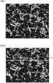
- the content ratio (volume%) of the cBN grains can be found as follows. First, the cBN sintered material is cut at an arbitrary location to produce a specimen including a cross section of the cBN sintered material. For the formation of the cross section, a focused ion beam device, a cross section polisher device, or the like can be used. Next, the cross section is observed by the SEM at a magnification of 5000x to obtain a reflected electron image. In the reflected electron image, the cBN grains look black (dark fields) and a region having the binder phase existing therein is gray or white (bright fields).
- the reflected electron image is subjected to binarization processing using image analysis software (for example, "WinROOF” provided by Mitani Corporation).
- image analysis software for example, "WinROOF” provided by Mitani Corporation.
- the calculated area ratio is regarded as volume%, thereby finding the content ratio (volume%) of the cBN grains.
- the area ratio of pixels originated from the bright fields (pixels originated from the binder phase) in the area of the measurement visual field is calculated, thereby finding the content ratio (volume%) of the binder phase.
- Fig. 1 shows an exemplary reflected electron image obtained by observing the cBN sintered material using the SEM.
- the reflected electron image is loaded into image processing software.
- the loaded image is shown in Fig. 2 .
- an arbitrary line Q1 is drawn in the loaded image.
- a concentration is measured along line Q1 in the cross sectional view, and a GRAY value is read.
- a graph (hereinafter, also referred to as a "concentration cross section graph”) is prepared with the X coordinate representing line Q1 and the Y coordinate representing the GRAY value.
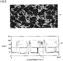
- Fig. 3 shows the reflected electron image of the cBN sintered material and the concentration cross section graph of the reflected electron image (the upper image corresponds to the reflected electron image and the lower graph corresponds to the concentration cross section graph).
- the width of the reflected electron image coincides with the width (23.27 ⁇ m) of the X coordinate of the concentration cross section graph.
- a distance from the left end portion of line Q1 to a specific position on line Q1 in the reflected electron image is represented by a value of the X coordinate in the concentration cross section graph.
- a region looking black and having cBN grains existing therein is arbitrarily selected at three locations.
- the region looking black corresponds to, for example, portions indicated by ellipses each denoted by a reference character "c" in the reflected electron image of Fig. 4 .
- the GRAY values of the region looking black at the three locations are read from the concentration cross section graph.
- the GRAY value of the region looking black at each of the three locations is the average value of the GRAY values of portions surrounded by a corresponding ellipse denoted by reference character "c" in the concentration cross section graph of Fig. 4 .
- the average value of the GRAY values at the three locations is calculated. This average value is defined as "cBN GRAY value" (hereinafter, also referred to as "G cbn ").
- a region in which the binder phase indicated by a gray color exists is arbitrarily selected at three locations.
- the binder phase corresponds to, for example, portions indicated by ellipses denoted by a reference character "d" in the reflected electron image of Fig. 4 .
- the GRAY values of the binder phase at the three locations are read from the concentration cross section graph.
- the GRAY value of the binder phase at each of the three locations is the average value of the GRAY values of portions at a corresponding one of the three locations surrounded by the ellipses denoted by reference character "d" in the concentration cross section graph of Fig. 4 .
- the average value of the GRAY values at the three locations is calculated. This average value is defined as "binder phase GRAY value” (hereinafter, also referred to as "Gbinder").
- a GRAY value indicated by (G cbn +G binder )/2 is defined as the GRAY value of an interface between each cBN grain (region looking black) and the binder phase.
- GRAY value G cbn of the cBN grains (region looking black) is indicated by a line G cbn
- GRAY value G binder of the binder phase is indicated by a line G binder
- the GRAY value indicated by (G cbn +G binder )/2 is indicated by a line G1.
- the values of the X coordinate and the Y coordinate at the interface between the cBN grain (region looking black) and the binder phase can be read in the concentration cross section graph.
- the interface can be arbitrarily defined. For example, in a reflected electron image at the upper part of Fig. 5 , a portion surrounded by an ellipse denoted by a reference character "e" is shown as an exemplary portion including the interface. In the reflected electron image of Fig. 5 , the interface between the cBN grain (region looking black) and the binder phase is, for example, the portion indicated by the ellipse denoted by reference character "e".
- the interface which corresponds to the ellipse denoted by the reference character "e" between the cBN grain (region looking black) and the binder phase is a portion indicated by an arrow e.
- the tip of arrow e indicates the position of an intersection point between the concentration cross section graph of the GRAY value and line G1 indicating the GRAY value (G cbn +G binder )/2.
- the values of the X coordinate of the tip of arrow e and the Y coordinate of the tip of arrow e correspond to the values of the X coordinate and the Y coordinate at the interface between the cBN grain (region looking black) and the binder phase.
- the binarization processing is performed using, as threshold values, the values of the X coordinate and the Y coordinate at the interface between the cBN grain (region looking black) and the binder phase.
- Fig. 6 shows an image having been through the binarization processing.
- a region surrounded by a dotted line is a region having been through the binarization processing.
- the image having been through the binarization processing may include not only the bright fields and the dark fields but also white regions (portions whiter than the bright fields) corresponding to the regions white in the image yet to be through the binarization processing.
- Fig. 6 the area ratio of pixels originated from the dark fields (pixels originated from the cBN grains) in the area of the measurement visual field is calculated.
- the calculated area ratio is regarded as volume%, thereby finding the content ratio (volume%) of the cBN grains.
- the area ratio of pixels originated from the bright fields (pixels originated from the binder phase) in the area of the measurement visual field is calculated, thereby finding the content ratio (volume%) of the binder phase.
- the cBN grains have high hardness, high strength, and high toughness, and serve as a base of the cBN sintered material.
- Median size D 50 (hereinafter, referred to as "average grain size") of the cBN grains is not particularly limited, and can be 0.1 to 10.0 ⁇ m, for example. Normally, as D 50 is smaller, the hardness of the cBN sintered material tends to be higher, and as variation in the grain sizes is smaller, the characteristics of the cBN sintered material tend to be more uniform.
- D 50 of the cBN grains is preferably, for example, 0.5 to 4.0 ⁇ m.
- D 50 of the cBN grains is determined as follows. First, a specimen including a cross section of the cBN sintered material is formed in the same manner as in the above-described method of finding the content ratio of the cBN grains, and a reflected electron image is obtained. Next, the equivalent circle diameter of each dark field (corresponding to cBN) in the reflected electron image is calculated using image analysis software ("WinROOF (ver.7.4.5)") provided by Mitani Corporation). It is preferable to calculate the equivalent circle diameters of 100 or more cBN grains by performing observation in five or more visual fields.
- WinROOF image analysis software
- D 50 represents a grain size corresponding to a cumulative area of 50% in the cumulative distribution. It should be noted that the equivalent circle diameter refers to the diameter of a circle having the same area as the area of the measured cBN grain.
- the binder phase serves to allow the cBN grains, each of which is a material difficult to be sintered, to be sintered at industrial levels of pressure and temperature. Moreover, reactivity of the binder phase with respect to iron is lower than that of cBN. Hence, in cutting of a high-strength hardened steel, the binder phase additionally works to suppress chemical wear and thermal wear. Moreover, when the cBN sintered material contains the binder phase, wear resistance in high-efficient processing of a high-strength hardened steel is improved.
- the binder phase includes the first binder grains and the second binder grains.
- Each of the first binder grains and the second binder grains includes one compound composed of titanium, the at least one first metal element selected from the group consisting of zirconium, hafnium, the group 5 element, the group 6 element in the periodic table, and aluminum, and one or both of nitrogen and carbon, in each of the first binder grains, the ratio of the number of atoms of the first metal element to the total of the number of atoms of titanium and the number of atoms of the first metal element is more than or equal to 0.01% and less than 10%, and in each of the second binder grains, the ratio of the number of atoms of the first metal element to the total of the number of atoms of titanium and the number of atoms of the first metal element is more than or equal to 10% and less than or equal to 80%.
- the first binder grain and the second binder grain are different from each other in terms of the ratio of the number of atoms of
- the group 5 element in the periodic table includes vanadium (V), niobium (Nb), and tantalum (Ta), for example.
- the group 6 element includes chromium (Cr), molybdenum (Mo), and tungsten (W), for example.
- the first metal element preferably consists of at least one metal element selected from a group consisting of zirconium, hafnium, niobium, tantalum, molybdenum, and tungsten.
- Examples of the compound (nitride) including titanium, the first metal element, and nitrogen include titanium zirconium nitride (TiZrN), titanium hafnium nitride (TiHfN), titanium vanadium nitride (TiVN), titanium niobium nitride (TiNbN), titanium tantalum nitride (TiTaN), titanium chromium nitride (TiCrN), titanium molybdenum nitride (TiMoN), titanium tungsten nitride (TiWN), titanium aluminum nitride (TiAlN, Ti 2 AlN, Ti 3 AlN), and the like.
- TiZrN titanium zirconium nitride
- TiHfN titanium hafnium nitride
- TiVN titanium vanadium nitride
- TiNbN titanium niobium nitride
- TiTaN titanium tantalum
- Examples of the compound (carbide) including titanium, the first metal element, and carbon include titanium zirconium carbide (TiZrC), titanium hafnium carbide (TiHfC), titanium vanadium carbide (TiVC), titanium niobium carbide (TiNbC), titanium tantalum carbide (TiTaC), titanium chromium carbide (TiCrC), titanium molybdenum carbide (TiMoC), titanium tungsten carbide (TiWC), titanium aluminum carbide (TiAlC, Ti 2 AlC, Ti 3 AlC), and the like.
- TiZrC titanium zirconium carbide
- TiHfC titanium hafnium carbide
- TiVC titanium vanadium carbide
- TiNbC titanium niobium carbide
- TiTaC titanium tantalum carbide
- TiCrC titanium chromium carbide
- TiMoC titanium molybdenum carbide
- TiWC titanium tungsten carbide
- Examples of the compound (carbonitride) including titanium, the first metal element, carbon and nitrogen include titanium zirconium carbonitride (TiZrCN), titanium hafnium carbonitride (TiHfCN), titanium vanadium carbonitride (TiVCN), titanium niobium carbonitride (TiNbCN), titanium tantalum carbonitride (TiTaCN), titanium chromium carbonitride (TiCrCN), titanium molybdenum carbonitride (TiMoCN), titanium tungsten carbonitride (TiWCN), titanium aluminum carbonitride (TiAlCN, Ti 2 AlCN, Ti 3 AlCN), and the like.
- TiZrCN titanium zirconium carbonitride
- TiHfCN titanium hafnium carbonitride
- TiVCN titanium vanadium carbonitride
- TiNbCN titanium niobium carbonitride
- TiTaCN titanium tantalum carbonitride
- TiCrCN titanium
- Each of the first binder grains and the second binder grains can consist only of the binder phase compound.
- each of the first binder grains and the second binder grains can include other component(s) in addition to the binder phase compound.
- element(s) of the other component(s) include nickel (Ni), iron (Fe), manganese (Mn) and rhenium (Re).
- the binder phase can include a solid solution originated from the compound described above.
- the solid solution originated from the compound refers to a state in which two or more of the compounds illustrated above are dissolved in the crystal structures of the compounds, and refers to an interstitial solid solution or a substitutional solid solution.
- the binder phase can consist only of the first binder grains and the second binder grains.
- the binder phase can include other component(s) in addition to the first binder grains and the second binder grains.
- element(s) of the other component(s) include nickel (Ni), iron (Fe), manganese (Mn) and rhenium (Re).
- the composition of the whole of the binder phase included in the cBN sintered material can be confirmed by combining structure observation, element analysis, and the like with crystal structure analysis and the like.
- the structure observation, element analysis, and the like use an energy dispersive X-ray analysis device (EDX) ("Octane Elect EDS system” (trademark)) accompanied with a scanning electron microscope (SEM) ("JSM-7800F” (trademark) provided by JEOL), and the crystal structure analysis and the like use XRD (X-ray diffraction measurement) (device: "MiniFlex 600" (trademark) provided by RIGAKU).
- EDX energy dispersive X-ray analysis device
- SEM scanning electron microscope
- JSM-7800F JSM-7800F
- XRD X-ray diffraction measurement
- the ratio of the number of atoms of the first metal element to the total of the number of atoms of titanium and the number of atoms of the first metal element is more than or equal to 0.01% and less than 10%.
- a difference in lattice constant between the first binder grain and the second binder grain becomes large.
- the ratio of the number of atoms of the first metal element to the total of the number of atoms of titanium and the number of atoms of the first metal element is preferably more than or equal to 0.02% and less than or equal to 5%, and is more preferably more than or equal to 0.05% and less than or equal to 3%.
- the ratio of the number of atoms of the first metal element to the total of the number of atoms of titanium and the number of atoms of the first metal element is more than or equal to 10% and less than or equal to 80%.
- the ratio of the number of atoms of the second metal element is more than or equal to 10%, lattice defects in the second binder grains are increased to suppress propagation of crack in the binder phase, thereby significantly improving the breakage resistance of the cubic boron nitride sintered material.
- the ratio of the number of atoms of the second metal element is less than or equal to 80%, the second binder grains can have excellent strength, thereby improving the strength of the cubic boron nitride sintered material.
- the ratio of the number of atoms of the first metal element to the total of the number of atoms of titanium and the number of atoms of the first metal element is preferably more than or equal to 11.5% and less than or equal to 60%, and is more preferably more than or equal to 13% and less than or equal to 50%.
- (1-1) to (1-5) the following describes: a procedure of a method of measuring the compositions of the first binder grain and the second binder grain; and a procedure of a method of measuring the ratio (hereinafter, also referred to as "the ratio of the first metal element") of the number of atoms of the first metal element to the total of the number of atoms of titanium and the number of atoms of the first metal element in each of the first binder grain and the second binder grain.
- a sample is obtained from the cBN sintered material, and is sliced to have a thickness of 30 to 100 nm using an argon ion slicer (provided by JEOL), thereby producing a cut piece.
- the cut piece is observed using a transmission electron microscope ("JEM-F200" (trade name) provided by JEOL; hereinafter, also referred to as "TEM") at a magnification of 50,000x, thereby obtaining a first image.
- JEM-F200 transmission electron microscope
- TEM transmission electron microscope
- a region other than the cBN grains (black) in the first image is positioned at the center of the visual field and observation is performed at an observation magnification changed to 100,000x, thereby obtaining a second image.
- a composition at the point at which the intensity of the signal of the first metal element is maximum is specified.
- the composition corresponds to the composition of the second binder grain.
- the ratio (the ratio of the first metal element) of the number of atoms of the first metal element to the total of the number of atoms of titanium and the number of atoms of the first metal element at the point at which the intensity of the signal of the first metal element is maximum is calculated.
- the ratio is calculated at each of 10 or more visual fields.
- the average value of the ratios at the 10 or more visual fields corresponds to the ratio of the first metal element in the second binder grain.
- a composition at the point at which the intensity of the signal of the first metal element is minimum is specified.
- the composition corresponds to the composition of the first binder grain.
- the ratio (the ratio of the first metal element) of the number of atoms of the first metal element to the total of the number of atoms of titanium and the number of atoms of the first metal element at the point at which the intensity of the signal of the first metal element is minimum is calculated.
- the ratio is calculated at each of 10 or more visual fields.
- the average value of the ratios at the 10 or more visual fields corresponds to the ratio of the first metal element in the first binder grain.
- a high-angle annular dark field scanning transmission electron microscope is used to obtain an HAADF-STEM image from the same visual field as that of the first image obtained in (1-1).
- a bright-field scanning transmission electron microscope is used to obtain a BF-STEM image from the same visual field as that of the first image obtained in (1-1).
- the crystal grains are specified based on the first image, the HAADF-STEM image, and the BF-STEM image.
- a grain boundary between the crystal grains is specified by the following method. First, in the obtained mapping image of the first metal element (M), an image is obtained in which a region in which the M content (atomic%)/(Ti content (atomic%) + the M content (atomic%)) is less than 10% is set not to be presented. In this image, reference is made to the element mapping obtained in (1-3) so as to define, as the crystal grains, mapping regions of the first metal element (M) in which boron is not observed and so as to specify, as the crystal grain boundary, a boundary between the mapping regions of the first metal element (M).
- the average grain size of the second binder grains is more than or equal to 0.2 ⁇ m and less than or equal to 1 ⁇ m.
- the second binder grains can maintain excellent toughness and heat conductivity.
- the average grain size of the second binder grains is preferably more than or equal to 0.25 ⁇ m and less than or equal to 0.7 ⁇ m, and is more preferably more than or equal to 0.3 ⁇ m and less than or equal to 0.6 ⁇ m.
- the average grain size of the second binder grains refers to the average value of the equivalent circle diameters of the crystal grains of 10 or more arbitrarily selected second binder grains.
- Fig. 7 shows an image obtained by loading, into the image processing software, the element mapping image obtained by observing the cBN sintered material using the TEM-EDX. As shown in Fig. 7 , an arbitrary line Q2 is drawn in the loaded image.
- Measurement is performed along line Q2 in a cross sectional view for concentration, and a GRAY value is read.
- a graph (hereinafter, also referred to as "concentration cross section graph") is prepared with the X coordinate representing line Q2 and the Y coordinate representing the GRAY value.
- Fig. 8 shows the concentration cross section graph of the image of Fig. 7 .
- values that are more than equal to a value obtained by multiplying maximum value H of the GRAY value by ⁇ / ⁇ are defined as the second binder grains, and the binarization processing is performed with the X coordinate and the Y coordinate of a boundary therebetween being used as threshold values.
- An image having been through the binarization is shown in Fig. 9 , and shows the second binder grains.
- the equivalent circle diameter of each of the bright fields is calculated.
- the calculated value corresponds to the equivalent circle diameter of each of the crystal grains of the second binder grains.
- the ratio of the mass of the first binder grains to the total mass of the first binder grains and the second binder grains is preferably more than or equal to 10% and less than or equal to 95%.
- crystal grains having different lattice constants are adjacent to each other, which leads to misaligned grain boundaries to improve the strength due to effects of lattice defects and stress, thereby improving the breakage resistance.
- the ratio of the mass of the first binder grains to the total of the masses of the first binder grains and the second binder grains is more preferably more than or equal to 30% and less than or equal to 90%, and is further preferably more than or equal to 50% and less than or equal to 80%.
- the ratio of the mass of the first binder grains to the total mass of the first binder grains and the second binder grains can be measured by an X-ray diffraction method. A specific measurement method will be described in (3-1) to (3-3) below.
- the cubic boron nitride sintered material is processed using a surface polishing device and is then mirror-polished by a mirror-polishing device, and the mirror-polished surface is regarded as an observation surface.
- Peak intensity A When the obtained X-ray diffraction spectrum data is read using the analysis software ("PDXL2" (trade name) provided by Rigaku), background is automatically calculated, and a value obtained by subtracting the background therefrom is presented at an item for the height of the peak information of the (220) plane of the first binder grain. This value is peak intensity A.
- Peak intensity B When the obtained X-ray diffraction spectrum data is read using the analysis software, PDXL2, background is automatically calculated, and a value obtained by subtracting the background therefrom is presented at an item for the height of the peak information of the (220) plane of the second binder grain. This value is peak intensity B.
- the ratio of the mass of the first binder grains to the total mass of the first binder grains and the second binder grains is obtained by calculating a value obtained by: peak intensity A / (peak intensity A + peak intensity B).
- Fig. 10 shows an exemplary X-ray diffraction spectrum obtained in (3-2).
- part of the peak (S1) of the first binder grains and part of the peak (S2) of the second binder grains may overlap with each other, with the result that a shoulder may be observed on the high angle side or low angle side of one peak (S).
- analysis is performed with the one peak being recognized as two peaks in the analysis software ("PDXL2" (trade name) provided by Rigaku).
- the shoulder on the low angle side or high angle side (low angle side in Fig. 10 ) of the one peak is regarded as the peak of the second binder grains, the peak is added using a peak addition function, and fitting is performed.
- the above-described X-ray peak intensity ratio can be regarded as the mass ratio in the cubic boron nitride sintered material.
- the method of producing the cBN sintered material according to the present disclosure can include: a step (hereinafter, also referred to as "preparation step”) of preparing a cubic boron nitride powder (hereinafter, also referred to as "cBN powder"), a first binder powder and a second binder powder; a step (hereinafter, also referred to as “formulation step”) of formulating a powder mixture by mixing the cBN powder and the binder powder; and a step (hereinafter, also referred to as "sintering step”) of obtaining the cubic boron nitride sintered material by sintering the powder mixture.
- preparation step of preparing a cubic boron nitride powder (hereinafter, also referred to as "cBN powder"), a first binder powder and a second binder powder
- a step hereinafter, also referred to as "formulation step” of formulating a powder mixture by mixing the cBN powder and the binder powder
- the cBN powder and the binder powder are prepared.
- the cBN powder is a source material powder for the cBN grains included in the cBN sintered material.
- the cBN powder is not particularly limited and known cBN powder can be used.
- the binder powder is a source material powder for the binder phase included in the cBN sintered material.
- a compound included in the binder phase of the cBN sintered material according to the present disclosure is formed by dissolving, in a solid state, the first metal element having an atomic radius different from that of titanium (Ti) in TiC x N y (x ⁇ 0, y ⁇ 0, and x+y>0), and has a composition of TiM2C x N y (x ⁇ 0, y ⁇ 0, x+y>0, M2 represents one or more first metal elements, and the ratio of the number of atoms of M2 to the total of the number of atoms of Ti and the number of atoms of M2 is more than or equal to 10% and less than or equal to 80%).
- the binder having the composition of TiM2C x N y will be referred to as "main binder”.
- a main binder powder in which a metal element having a different atomic radius is dissolved in titanium in a solid state can be produced by performing heat treatment (hereinafter, also referred to as "high-temperature heat treatment") onto the source material for the main binder at a high temperature of more than or equal to 1800°C. Further, it has been found that such a main binder powder in which a metal element having a different atomic radius is dissolved in titanium in a solid state can also be produced by performing powder thermal plasma treatment onto an element powder included in the main binder. Details of the high-temperature heat treatment and the powder thermal plasma treatment will be described as follows.
- the following describes an exemplary method of producing the main binder powder by using the high-temperature heat treatment.
- a main binder powder mixture is obtained by mixing: a TiO 2 powder; an oxide powder of at least one element selected from a group consisting of zirconium, hafnium, a group 5 element, a group 6 element in the periodic table, and aluminum; and a carbon (C) powder.
- oxide powder of the first metal element examples include zirconium oxide (ZrO 2 ), hafnium oxide (HfO 2 ), vanadium oxide (V 2 O 5 ), niobium oxide (Nb 2 O 5 ), tantalum oxide (Ta 2 O 5 ), chromium oxide (Cr 2 O 3 ), molybdenum oxide (MoO 3 ), and tungsten oxide (WO 3 ).
- the obtained main binder powder mixture is subjected to heat treatment at 1800°C to 2200°C for 60 minutes under a nitrogen atmosphere.
- a single-phase compound having a composition of TiM2C x N y is synthesized.
- the single-phase compound is pulverized to attain a desired grain size in accordance with a wet pulverization method, thereby obtaining a main binder powder having a composition of TiM2C x N y .
- the following describes an exemplary method of producing the main binder powder by using the powder thermal plasma treatment.
- a binder powder mixture is obtained by mixing a titanium (Ti) powder, an M (first metal element) powder, and a carbon (C) powder.
- the obtained binder powder mixture is subjected to treatment using a thermal powder plasma device (TP-40020NPS provided by JEOL).
- a thermal powder plasma device TP-40020NPS provided by JEOL.
- the main binder powder mixture is set in a chamber of the thermal powder plasma device so as to perform treatment thereto by introducing N 2 gas at a flow rate of 30 L/min under a condition of an output of 6 kW.
- N 2 gas at a flow rate of 30 L/min under a condition of an output of 6 kW.
- Ti 2 AlN and/or Ti 2 AlC are preferably used as a sub-binder.
- the use of the sub-binder promotes binding of the cBN grains and the main binder.
- a compound having a composition of TiM1C x N y (x ⁇ 0, y ⁇ 0, x+y>0, M1 represents the same first metal element as M2, and the ratio of the number of atoms of M1 to the total of the number of atoms of Ti and the number of atoms of M1 is more than or equal to 0.01% and less than 10%) is generated from part of the first metal element (M2) included in the main binder powder and the sub-binder powder.
- the compound having the composition of TiM1C x N y constitutes the first binder grains in the cBN sintered material.
- the obtained sub-binder powder mixture is subjected to heat treatment at 1500°C for 60 minutes under an argon atmosphere.
- a single-phase compound having a composition of Ti 2 AlC is synthesized.
- the single-phase compound is pulverized to attain a desired grain size in accordance with a wet pulverization method, thereby obtaining a sub-binder powder having a composition of Ti 2 AlC.
- This step is a step of formulating a powder mixture by mixing the cBN powder and the binder powder.
- the binder powder can include the main binder powder and the sub-binder powder.
- the mixing ratio of the cBN powder and the binder powder is adjusted such that the ratio of the cBN powder in the powder mixture becomes more than or equal to 20 volume% and less than or equal to 80 volume% and the ratio of the binder powder becomes more than or equal to 20 volume% and less than or equal to 80 volume%.
- the mixing ratio of the cBN powder and the binder powder in the powder mixture is substantially the same as the ratio of the cBN grains and the binder phase in the cBN sintered material obtained by sintering the powder mixture. Therefore, by adjusting the mixing ratio of the cBN powder and the binder powder in the powder mixture, the ratio of the cBN grains and the binder phase in the cBN sintered material can be adjusted to fall within a desired range.
- the method of mixing the cBN powder and the binder powder is not particularly limited; however, in order to efficiently and uniformly mix the powders, ball mill mixing, bead mill mixing, planetary mill mixing, jet mill mixing, or the like can be used. Each of the mixing methods may be performed in a wet manner or dry manner.
- the cBN powder and the binder powder are preferably mixed by wet ball mill mixing employing ethanol, acetone or the like as a solvent. After the mixing, the solvent is removed by natural drying. Thereafter, an impurity such as moisture adsorbed on the surfaces is volatilized by heat treatment to clean the surfaces. Thus, the powder mixture is formulated.
- This step is a step of obtaining the cBN sintered material by sintering the powder mixture.
- the powder mixture is sintered under a high-temperature and high-pressure condition, thereby producing the cBN sintered material.
- high-temperature heat treatment for example, more than or equal to 900°C heat treatment
- degassing treatment high-temperature heat treatment
- the powder mixture having been through the degassing treatment is provided in a capsule for ultra-high pressure sintering, and is vacuum-sealed by using a metal as a sealing material in vacuum.
- the vacuum-sealed powder mixture is sintered using an ultra-high temperature and high-pressure device.
- Sintering conditions are preferably 5.5 to 8 GPa, more than or equal to 1200°C and less than 1800°C, and 5 to 60 minutes, for example.
- 6 to 7 GPa, 1400 to 1600°C, and 10 to 30 minutes are preferable.
- the cBN sintered material is produced.
- the cubic boron nitride sintered material according to the present disclosure can be used as a tool material.
- the tool can include the cBN sintered material as a substrate. Further, the tool may have a coating film on a surface of the cBN sintered material serving as the substrate.
- the shape and purpose of use of the tool are not limited particularly.
- Examples of the tool include a drill, an end mill, an indexable cutting insert for drill, an indexable cutting insert for end mill, an indexable cutting insert for milling, an indexable cutting insert for turning, a metal saw, a gear cutting tool, a reamer, a tap, an insert for crankshaft pin milling, and the like.
- the tool according to the present embodiment is not limited only to a tool entirely composed of the cBN sintered material, and includes a tool having a portion (particularly, a cutting edge portion or the like) composed of the cBN sintered material.
- the tool according to the present embodiment also includes a tool in which a base body (supporting body) composed of a cemented carbide or the like has a cutting edge portion composed of the cBN sintered material.
- the cutting edge portion is literally regarded as a tool.
- the cBN sintered material is referred to as a tool.
- the tool according to the present embodiment includes the above-described cBN sintered material, a long life of the tool can be attained.
- a cBN powder (average particle size: 3 ⁇ m), a main binder powder (TiNbCN powder), and a sub-binder powder (Ti 2 AlC powder) were prepared.
- a commercially available cBN powder was prepared.
- the main binder powder (TiNbCN powder) was produced by the method using the high-temperature heat treatment. Specifically, a main binder powder mixture was obtained by mixing a TiO 2 powder, a Nb 2 O 5 powder, and a carbon (C) powder at a weight ratio of 57.19 : 16.79 : 26.02. The main binder powder mixture was subjected to heat treatment at 2250°C for 60 minutes under a nitrogen atmosphere, thereby synthesizing a single-phase compound having a composition of TiNbCN.
- the single-phase compound was pulverized using a bead mill ("LABSTAR Mini" (trade name) provided by Ashizawa Finetech). Specifically, the single-phase compound and ZrO 2 beads were introduced into an ethanol solvent to form a slurry having a slurry concentration of 20%. The slurry was introduced into the bead mill and pulverization was performed for 1.5 hours, thereby obtaining a TiNbCN powder having an average particle size of 0.5 ⁇ m.
- the TiNbCN powder (main binder powder) and a Ti 2 AlC powder (sub-binder powder) were mixed to prepare a binder powder.
- the mixing ratio of the TiNbCN powder (main binder powder) and the Ti 2 AlC powder (sub-binder powder) was adjusted such that the ratio of the first binder grains and the second binder grains in the sintered material became 70 : 30 in weight.
- the cBN powder and the binder powder were mixed uniformly using a ball mill, thereby obtaining a powder mixture.
- the obtained powder mixture was provided in a Ta container with the powder mixture being in contact with a WC-6% Co cemented carbide disc, was vacuum-sealed, and was sintered at 6.5 GPa and 1500°C for 15 minutes using a belt-type ultra-high pressure and high temperature generation device. Thus, a cBN sintered material was produced.
- a cBN sintered material was produced in the same manner as in Specimen 1 except that the pulverization was performed such that the TiNbCN powder (main binder powder) had an average particle size of 0.23 ⁇ m (pulverization time: 2.2 hours) in the preparation step.
- a cBN sintered material was produced in the same manner as in Specimen 1 except that the pulverization was performed such that the TiNbCN powder (main binder powder) had an average particle size of 0.1 ⁇ m (pulverization time: 3.0 hours) in the preparation step.
- a cBN sintered material was produced in the same manner as in Specimen 1 except that a TiO 2 powder, a Nb 2 O 5 powder, and a carbon (C) powder were mixed at a weight ratio of 70.49 : 2.39 : 27.12 in the preparation step.
- Each of cBN sintered materials was produced in the same manner as in Specimen 1 except that in the preparation step, the mixing ratio of the TiNbCN powder (main binder powder) and the Ti 2 AlC powder (sub-binder powder) was adjusted such that the ratio of the first binder grains and the second binder grains in the sintered material became 51 : 49 in the case of Specimen 5, 92 : 8 in the case of Specimen 6, 25 : 75 in the case of Specimen 7, 96 : 4 in the case of Specimen 8, and 5 : 95 in the case of Specimen 9 in weight.
- a cBN sintered material was produced in the same manner as in Specimen 1 except that a TiZrCN powder was used as the main binder powder instead of the TiNbCN powder.
- the TiZrCN powder was produced by the following method. A TiO 2 powder, a ZrO 2 powder, and a carbon (C) powder were mixed at a weight ratio of 58.35 : 15.88 : 25.77, thereby obtaining a binder powder mixture. The binder powder mixture was subjected to heat treatment at 2250°C for 60 minutes under a nitrogen atmosphere, thereby synthesizing a single-phase compound having a composition of TiZrCN.
- the single-phase compound was pulverized using a bead mill ("LABSTAR Mini" (trade name) provided by Ashizawa Finetech). Specifically, the single-phase compound and ZrO 2 beads were introduced into an ethanol solvent to form a slurry having a slurry concentration of 20%. The slurry was introduced into the bead mill and pulverization was performed for 1.5 hours, thereby obtaining a TiZrCN powder having an average particle size of 0.5 ⁇ m.
- a cBN sintered material was produced in the same manner as in Specimen 1 except that a TiMoCN powder was used as the main binder powder instead of the TiNbCN powder.
- the TiMoCN powder was produced by the following method. A TiO 2 powder, a MoO 3 powder, and a carbon (C) powder were mixed at a weight ratio of 55.99 : 17.80 : 26.21, thereby obtaining a binder powder mixture. The binder powder mixture was subjected to heat treatment at 2250°C for 60 minutes under a nitrogen atmosphere, thereby synthesizing a single-phase compound having a composition of TiMoCN.
- the single-phase compound was pulverized using a bead mill ("LABSTAR Mini" (trade name) provided by Ashizawa Finetech). Specifically, the single-phase compound and ZrO 2 beads were introduced into an ethanol solvent to form a slurry having a slurry concentration of 20%. The slurry was introduced into the bead mill and pulverization was performed for 1.5 hours, thereby obtaining a TiMoCN powder having an average particle size of 0.5 ⁇ m.
- a cBN sintered material was produced in the same manner as in Specimen 1 except that a TiHfCN powder was used as the main binder powder instead of the TiNbCN powder.
- the TiHfCN powder was produced by the following method. A TiO 2 powder, a HfO 2 powder, and a carbon (C) powder were mixed at a weight ratio of 52.45 : 24.38 : 23.17, thereby obtaining a binder powder mixture. The binder powder mixture was subjected to heat treatment at 2250°C for 60 minutes under a nitrogen atmosphere, thereby synthesizing a single-phase compound having a composition of TiHfCN.
- the single-phase compound was pulverized using a bead mill ("LABSTAR Mini" (trade name) provided by Ashizawa Finetech). Specifically, the single-phase compound and ZrO 2 beads were introduced into an ethanol solvent to form a slurry having a slurry concentration of 20%. The slurry was introduced into the bead mill and pulverization was performed for 1.5 hours, thereby obtaining a TiHfCN powder having an average particle size of 0.5 ⁇ m.
- a cBN sintered material was produced in the same manner as in Specimen 1 except that a TiTaCN powder was used as the main binder powder instead of the TiNbCN powder.
- the TiTaCN powder was produced by the following method. A TiO 2 powder, a Ta 2 O 5 powder, and a carbon (C) powder were mixed at a weight ratio of 51.47 : 25.11 : 23.42, thereby obtaining a binder powder mixture. The binder powder mixture was subjected to heat treatment at 2250°C for 60 minutes under a nitrogen atmosphere, thereby synthesizing a single-phase compound having a composition of TiTaCN.
- the single-phase compound was pulverized using a bead mill ("LABSTAR Mini" (trade name) provided by Ashizawa Finetech). Specifically, the single-phase compound and ZrO 2 beads were introduced into an ethanol solvent to form a slurry having a slurry concentration of 20%. The slurry was introduced into the bead mill and pulverization was performed for 1.5 hours, thereby obtaining a TiTaCN powder having an average particle size of 0.5 ⁇ m.
- a cBN sintered material was produced in the same manner as in Specimen 1 except that a TiWCN powder was used as the main binder powder instead of the TiNbCN powder.
- the TiWCN powder was produced by the following method. A TiO 2 powder, a WO 3 powder, and a carbon (C) powder were mixed at a weight ratio of 51.53 : 26.39 : 22.08, thereby obtaining a binder powder mixture. The binder powder mixture was subjected to heat treatment at 2250°C for 60 minutes under a nitrogen atmosphere, thereby synthesizing a single-phase compound having a composition of TiWCN.
- the single-phase compound was pulverized using a bead mill ("LABSTAR Mini" (trade name) provided by Ashizawa Finetech). Specifically, the single-phase compound and ZrO 2 beads were introduced into an ethanol solvent to form a slurry having a slurry concentration of 20%. The slurry was introduced into the bead mill and pulverization was performed for 1.5 hours, thereby obtaining a TiWCN powder having an average particle size of 0.5 ⁇ m.
- a cBN sintered material was produced in the same manner as in Specimen 1 except that a TiCrCN powder was used as the main binder powder instead of the TiNbCN powder.
- the TiCrCN powder was produced by the following method. A TiO 2 powder, a Cr 2 O 3 powder, and a carbon (C) powder were mixed at a weight ratio of 62.64 : 10.52 : 26.84, thereby obtaining a binder powder mixture. The binder powder mixture was subjected to heat treatment at 2250°C for 60 minutes under a nitrogen atmosphere, thereby synthesizing a single-phase compound having a composition of TiCrCN.
- the single-phase compound was pulverized using a bead mill ("LABSTAR Mini" (trade name) provided by Ashizawa Finetech). Specifically, the single-phase compound and ZrO 2 beads were introduced into an ethanol solvent to form a slurry having a slurry concentration of 20%. The slurry was introduced into the bead mill and pulverization was performed for 1.5 hours, thereby obtaining a TiCrCN powder having an average particle size of 0.5 ⁇ m.
- a cBN sintered material was produced in the same manner as in Specimen 1 except that a TiVCN powder was used as the main binder powder instead of the TiNbCN powder.
- the TiVCN powder was produced by the following method. A TiO 2 powder, a V 2 O 5 powder, and a carbon (C) powder were mixed at a weight ratio of 60.39 : 12.13 : 27.48, thereby obtaining a binder powder mixture. The binder powder mixture was subjected to heat treatment at 2250°C for 60 minutes under a nitrogen atmosphere, thereby synthesizing a single-phase compound having a composition of TiVCN.
- the single-phase compound was pulverized using a bead mill ("LABSTAR Mini" (trade name) provided by Ashizawa Finetech). Specifically, the single-phase compound and ZrO 2 beads were introduced into an ethanol solvent to form a slurry having a slurry concentration of 20%. The slurry was introduced into the bead mill and pulverization was performed for 1.5 hours, thereby obtaining a TiVCN powder having an average particle size of 0.5 ⁇ m.
- Each of cBN sintered materials was produced in the same manner as in Specimen 1 except that in the preparation step, the mixing ratio of the cBN powder and the binder powder was 74 : 26 in the case of Specimen 17, 40 : 60 in the case of Specimen 18, 78 : 22 in the case of Specimen 19, 22 : 78 in the case of Specimen 20, 85 : 15 in the case of Specimen 21, and 15 : 85 in the case of Specimen 22 in volume ratio.
- a cBN powder (average particle size: 3 ⁇ m), a main binder powder, and a sub-binder powder were prepared.
- the main binder powder was produced by the method using the high-temperature heat treatment. Specifically, a TiO 2 powder, a Cr 2 O 3 powder, and a carbon (C) powder were mixed at a weight ratio of 62.64 : 10.52 : 26.84, thereby obtaining a binder powder mixture.
- the binder powder mixture was subjected to heat treatment at 2250°C for 60 minutes under a nitrogen atmosphere, thereby synthesizing a single-phase compound having a composition of TiCrCN.
- the single-phase compound was pulverized using a bead mill ("LABSTAR Mini" (trade name) provided by Ashizawa Finetech). Specifically, the single-phase compound and ZrO 2 beads were introduced into an ethanol solvent to form a slurry having a slurry concentration of 20%. The slurry was introduced into the bead mill and pulverization was performed for 2 hours, thereby obtaining a TiCrCN powder having an average particle size of 0.25 ⁇ m.
- the TiCrCN powder (main binder powder) and a Ti 2 AlC powder (sub-binder powder) were mixed to prepare a binder powder.
- the mixing ratio of the TiCrCN powder (main binder powder) and the Ti 2 AlC powder (sub-binder powder) was adjusted such that the ratio of the first binder grains and the second binder grains in the sintered material became 96 : 4 in weight.
- the cBN powder and the binder powder were mixed uniformly using a ball mill, thereby obtaining a powder mixture.
- the obtained powder mixture was provided in a Ta container with the powder mixture being in contact with a WC-6% Co cemented carbide disc, was vacuum-sealed, and was sintered at 6.5 GPa and 1500°C for 15 minutes using a belt-type ultra-high pressure and high temperature generation device. Thus, a cBN sintered material was produced.
- a cBN sintered material was produced in the same manner as in Specimen 23 except that the pulverization was performed such that the TiCrCN powder (main binder powder) had an average particle size of 0.5 ⁇ m (pulverization time: 1.5 hours) in the preparation step.
- Each of cBN sintered materials was produced in the same manner as in Specimen 23 except that in the preparation step, the mixing ratio of the TiCrCN powder (main binder powder) and the Ti 2 AlC powder (sub-binder powder) was adjusted such that the ratio of the first binder grains and the second binder grains in the sintered material was 92 : 8 in the case of Specimen 25 and 70 : 30 in the case of Specimen 26 in weight.
- a cBN sintered material was produced in the same manner as Specimen 26 except that a TiHfCN powder was used as the main binder powder instead of the TiCrCN powder.
- the TiHfCN powder was produced in the same manner as Specimen 12.
- a cBN powder (average particle size: 3 ⁇ m), a main binder powder, and a sub-binder powder were prepared.
- the main binder powder was produced by the method using the high-temperature heat treatment. Specifically, a TiO 2 powder, a Nb 2 O 5 powder, and a carbon (C) powder were mixed at a weight ratio of 57.19 : 16.79 : 26.02, thereby obtaining a main binder powder mixture.
- the main binder powder mixture was subjected to heat treatment at 2250°C for 60 minutes under a nitrogen atmosphere, thereby synthesizing a single-phase compound having a composition of TiNbCN.
- the single-phase compound was pulverized using a bead mill ("LABSTAR Mini" (trade name) provided by Ashizawa Finetech). Specifically, the single-phase compound and ZrO 2 beads were introduced into an ethanol solvent to form a slurry having a slurry concentration of 20%. The slurry was introduced into the bead mill and pulverization was performed for 2.5 hours, thereby obtaining a TiNbCN powder having an average particle size of 0.2 ⁇ m.
- the TiNbCN powder (main binder powder) and an Al powder (Minalco 900F (trade name) provided by Minalco) were mixed to prepare a binder powder.
- the mixing ratio of the TiNbCN powder (main binder powder) and the Al powder was adjusted such that the ratio of aluminum (Al) in the binder powder became 5 weight%.
- the cBN powder and the binder powder were mixed uniformly using a ball mill, thereby obtaining a powder mixture.
- the obtained powder mixture was provided in a Ta container with the powder mixture being in contact with a WC-6% Co cemented carbide disc, was vacuum-sealed, and was sintered at 6.5 GPa and 1500°C for 15 minutes using a belt-type ultra-high pressure and high temperature generation device. Thus, a cBN sintered material was produced.
- a cBN sintered material was produced in the same manner as in Specimen 1 using the same binder as that in Specimen 1 except that the sintering temperature was set to 1300°C.
- a cBN sintered material was produced in the same manner as in Specimen 1 using the same binder as that in Specimen 1 except that the sintering temperature was set to 1800°C.
- a cBN sintered material was produced in the same manner as in Specimen 1 except that a TiO 2 powder, a Nb 2 O 5 powder, and a carbon (C) powder were mixed at a weight ratio of 62.10 : 11.48 : 26.42 in the preparation step.
- a cBN sintered material was produced in the same manner as in Specimen 1 except that a TiO 2 powder, a Nb 2 O 5 powder, and a carbon (C) powder were mixed at a weight ratio of 10.17 : 67.68 : 22.15 in the preparation step.
- a cBN sintered material was produced in the same manner as in Specimen 1 to have the same composition as that in Specimen 1 except that the pulverization was performed such that the TiNbCN powder (main binder powder) had an average particle size of 1.0 ⁇ m (pulverization time: 1 hour).
- a cBN sintered material was produced in the same manner as in Specimen 1 to have the same composition as that in Specimen 1 except that the pulverization was performed such that the TiNbCN powder (main binder powder) had an average particle size of 2.0 ⁇ m (pulverization time: 0.5 hour).
- a cBN sintered material was produced in the same manner as in Specimen 1 to have the same composition as that in Specimen 1 except that the pulverization was performed such that the TiNbCN powder (main binder powder) had an average particle size of 0.8 ⁇ m (pulverization time: 1.2 hours).
- a cBN sintered material was produced in the same manner as in Specimen 1 except that a TiAlCN powder (main binder powder) was used as the main binder powder instead of the TiNbCN powder.
- the TiAlCN powder was produced by the following method. A TiO 2 powder, an Al 2 O 3 powder, and a carbon (C) powder were mixed at a weight ratio of 64.89 : 7.31 : 27.80, thereby obtaining a binder powder mixture. The binder powder mixture was subjected to heat treatment at 2250°C for 60 minutes under a nitrogen atmosphere, thereby synthesizing a single-phase compound having a composition of TiAlCN.
- compositions of the first binder grains and the second binder grains and the contents (based on the number of atoms) of the constituent elements in the first binder grains and the second binder grains were measured using a TEM-EDX.
- a specific measurement method has been described in the first embodiment, and therefore will not be described repeatedly.
- the ratio of the number of atoms of titanium (hereinafter, also referred to as "Ti ratio”) and the ratio of the number of atoms of the first metal element (hereinafter, the ratio of the number of atoms of the first metal element in the first binder grain is also referred to as "M1 ratio”, and the ratio of the number of atoms of the first metal element in the second binder grain is also referred to as "M2 ratio”) to the total of the number of atoms of titanium and the number of atoms of the first metal element were calculated.
- Ti ratio the ratio of the number of atoms of titanium
- M2 ratio the ratio of the number of atoms of the first metal element in the first binder grain
- Cutting tools (tool model number: DNGA150412; cutting edge process: S01225) were produced in which the cBN sintered materials of Specimens 1 to 36 were used as cutting edges. A cutting test was performed using each of the cutting tools under the following cutting conditions.
- the cutting conditions described above correspond to high-efficiency processing of a high-strength hardened steel.
- the cutting edge was observed per cutting distance of 0.1 km to measure a size of chipping of the cutting edge.
- the size of chipping of the cutting edge was defined as the size of breakage in a principal force direction with respect to the position of the ridgeline of the cutting edge before the cutting.
- the cutting distance at a point of time at which the size of chipping of the cutting edge was more than or equal to 0.1 mm was measured. It should be noted that a longer cutting distance means a longer life of the cutting tool. Results are shown in the column "Distance (km)" in Tables 1-2, 2-2 and 3-2. [Table 1-1] Specimen No.
- the cBN sintered materials of Specimens 1, 2, 5 to 20, 23 to 27, 29 to 35, and 36 correspond to examples of the present disclosure. It was confirmed that when the cBN sintered material of each of these specimens is used as a tool material, an excellent tool life was exhibited even in high-efficiency processing of a high-strength hardened steel.
- the cBN sintered material of Specimen 3 in which the average grain size of the second binder grains was 0.1 ⁇ m, corresponds to a comparative example.
- the tool life was shorter than that of each of the examples of the present disclosure.
- the cBN sintered material of Specimen 4 in which the ratio of the number of atoms of the first metal element in the second binder grain was 2%, corresponds to a comparative example.
- the tool life was shorter than that of each of the examples of the present disclosure.
- the cBN sintered material of Specimen 21 in which the content ratio of the cBN grains is 85 volume%, corresponds to a comparative example.
- the tool life was shorter than that of each of the examples of the present disclosure.
- the cBN sintered material of Specimen 22 in which the content ratio of the cBN grain is 15 volume%, corresponds to a comparative example.
- the tool life was shorter than that of each of the examples of the present disclosure.
- the cBN sintered material of Specimen 28 which does not include the first binder grains, corresponds to a comparative example.
- the tool life was shorter than that of each of the examples of the present disclosure.
- the cBN sintered material of Specimen 34 in which the average grain size of the second binder grains was 2.0 ⁇ m, corresponds to a comparative example.
- the tool life was shorter than that of each of the examples of the present disclosure.
Landscapes
- Chemical & Material Sciences (AREA)
- Engineering & Computer Science (AREA)
- Ceramic Engineering (AREA)
- Manufacturing & Machinery (AREA)
- Materials Engineering (AREA)
- Organic Chemistry (AREA)
- Structural Engineering (AREA)
- Inorganic Chemistry (AREA)
- Crystallography & Structural Chemistry (AREA)
- Physics & Mathematics (AREA)
- Metallurgy (AREA)
- Thermal Sciences (AREA)
- Plasma & Fusion (AREA)
- Mechanical Engineering (AREA)
- Cutting Tools, Boring Holders, And Turrets (AREA)
- Ceramic Products (AREA)
Applications Claiming Priority (2)
| Application Number | Priority Date | Filing Date | Title |
|---|---|---|---|
| JP2019133028 | 2019-07-18 | ||
| PCT/JP2020/027904 WO2021010477A1 (fr) | 2019-07-18 | 2020-07-17 | Corps fritté en nitrure de bore cubique |
Publications (2)
| Publication Number | Publication Date |
|---|---|
| EP4001242A1 true EP4001242A1 (fr) | 2022-05-25 |
| EP4001242A4 EP4001242A4 (fr) | 2022-08-31 |
Family
ID=74209881
Family Applications (1)
| Application Number | Title | Priority Date | Filing Date |
|---|---|---|---|
| EP20841546.3A Pending EP4001242A4 (fr) | 2019-07-18 | 2020-07-17 | Corps fritté en nitrure de bore cubique |
Country Status (5)
| Country | Link |
|---|---|
| US (1) | US11518718B2 (fr) |
| EP (1) | EP4001242A4 (fr) |
| JP (1) | JP6928196B2 (fr) |
| CN (1) | CN114144392B (fr) |
| WO (1) | WO2021010477A1 (fr) |
Families Citing this family (1)
| Publication number | Priority date | Publication date | Assignee | Title |
|---|---|---|---|---|
| CN114922900B (zh) * | 2022-05-13 | 2023-08-08 | 咸阳职业技术学院 | 高温耐磨轴承及其制备方法 |
Family Cites Families (17)
| Publication number | Priority date | Publication date | Assignee | Title |
|---|---|---|---|---|
| JPH0621314B2 (ja) | 1985-12-28 | 1994-03-23 | 住友電気工業株式会社 | 高硬度工具用焼結体およびその製造方法 |
| JP3035797B2 (ja) | 1991-07-04 | 2000-04-24 | 三菱マテリアル株式会社 | 高強度を有する立方晶窒化ほう素基超高圧焼結材料製切削チップ |
| JPH07172924A (ja) * | 1993-12-17 | 1995-07-11 | Toshiba Tungaloy Co Ltd | 工具用高靭性焼結体およびその製造方法 |
| US5639285A (en) * | 1995-05-15 | 1997-06-17 | Smith International, Inc. | Polycrystallline cubic boron nitride cutting tool |
| JP3489297B2 (ja) * | 1995-11-15 | 2004-01-19 | 三菱マテリアル株式会社 | 高強度立方晶窒化硼素基焼結体製切削工具 |
| JP5100927B2 (ja) * | 2001-01-30 | 2012-12-19 | 昭和電工株式会社 | 立方晶窒化ホウ素焼結体の製造方法 |
| JP2003236710A (ja) * | 2001-12-11 | 2003-08-26 | Mitsubishi Materials Corp | 耐チッピング性のすぐれた立方晶窒化ほう素基超高圧焼結材料製切削チップ |
| JP4160898B2 (ja) * | 2003-12-25 | 2008-10-08 | 住友電工ハードメタル株式会社 | 高強度高熱伝導性立方晶窒化硼素焼結体 |
| CN100584797C (zh) * | 2004-10-28 | 2010-01-27 | 京瓷株式会社 | 立方氮化硼烧结材料以及利用其的切削工具 |
| JP4830571B2 (ja) * | 2006-03-27 | 2011-12-07 | 株式会社タンガロイ | cBN基超高圧焼結体 |
| JP6095162B2 (ja) * | 2013-03-29 | 2017-03-15 | 住友電工ハードメタル株式会社 | 立方晶窒化ホウ素焼結体 |
| JP6082650B2 (ja) | 2013-04-26 | 2017-02-15 | 株式会社タンガロイ | 立方晶窒化硼素焼結体および被覆立方晶窒化硼素焼結体 |
| WO2016143172A1 (fr) * | 2015-03-09 | 2016-09-15 | 住友電気工業株式会社 | Poudre céramique, et corps fritté en nitrure de bore |
| JP2017014084A (ja) * | 2015-07-03 | 2017-01-19 | 昭和電工株式会社 | 立方晶窒化硼素焼結体、立方晶窒化硼素焼結体の製造方法、工具、および切削工具 |
| JP6575858B2 (ja) | 2015-07-30 | 2019-09-18 | 三菱マテリアル株式会社 | 耐欠損性にすぐれた立方晶窒化硼素焼結体切削工具 |
| JP7219215B2 (ja) * | 2017-10-30 | 2023-02-07 | 住友電気工業株式会社 | 焼結体、及び、それを含む切削工具 |
| JP7011161B2 (ja) | 2018-01-31 | 2022-02-10 | Tianma Japan株式会社 | 表示装置 |
-
2020
- 2020-07-17 US US17/626,051 patent/US11518718B2/en active Active
- 2020-07-17 WO PCT/JP2020/027904 patent/WO2021010477A1/fr unknown
- 2020-07-17 JP JP2021503622A patent/JP6928196B2/ja active Active
- 2020-07-17 CN CN202080051851.2A patent/CN114144392B/zh active Active
- 2020-07-17 EP EP20841546.3A patent/EP4001242A4/fr active Pending
Also Published As
| Publication number | Publication date |
|---|---|
| JPWO2021010477A1 (ja) | 2021-09-13 |
| EP4001242A4 (fr) | 2022-08-31 |
| CN114144392B (zh) | 2023-06-02 |
| JP6928196B2 (ja) | 2021-09-01 |
| CN114144392A (zh) | 2022-03-04 |
| US11518718B2 (en) | 2022-12-06 |
| WO2021010477A1 (fr) | 2021-01-21 |
| US20220204412A1 (en) | 2022-06-30 |
Similar Documents
| Publication | Publication Date | Title |
|---|---|---|
| EP3578534B1 (fr) | Matériau fritté et outil de coupe le comprenant | |
| EP4000778A1 (fr) | Pièce compacte frittée de nitrure de bore cubique et son procédé de fabrication | |
| JP6908798B2 (ja) | 立方晶窒化硼素焼結体 | |
| EP4001242A1 (fr) | Corps fritté en nitrure de bore cubique | |
| KR20220095238A (ko) | 입방정 질화붕소 소결체 | |
| EP4000779A1 (fr) | Compact fritté en nitrure de bore cubique | |
| KR20220095243A (ko) | 입방정 질화붕소 소결체 | |
| EP4350022A1 (fr) | Carbure cémenté et outil le contenant | |
| JP6912685B2 (ja) | 立方晶窒化硼素焼結体 | |
| EP4001241A1 (fr) | Corps fritté en nitrure de bore cubique | |
| WO2021010471A1 (fr) | Corps fritté en nitrure de bore cubique, et outil de coupe | |
| EP4424655A1 (fr) | Corps fritté en nitrure de bore cubique | |
| EP4082994A1 (fr) | Corps fritté de nitrure de bore cubique et son procédé de production | |
| CN114206806A (zh) | 立方晶氮化硼烧结体以及切削工具 |
Legal Events
| Date | Code | Title | Description |
|---|---|---|---|
| STAA | Information on the status of an ep patent application or granted ep patent |
Free format text: STATUS: THE INTERNATIONAL PUBLICATION HAS BEEN MADE |
|
| PUAI | Public reference made under article 153(3) epc to a published international application that has entered the european phase |
Free format text: ORIGINAL CODE: 0009012 |
|
| STAA | Information on the status of an ep patent application or granted ep patent |
Free format text: STATUS: REQUEST FOR EXAMINATION WAS MADE |
|
| 17P | Request for examination filed |
Effective date: 20220117 |
|
| AK | Designated contracting states |
Kind code of ref document: A1 Designated state(s): AL AT BE BG CH CY CZ DE DK EE ES FI FR GB GR HR HU IE IS IT LI LT LU LV MC MK MT NL NO PL PT RO RS SE SI SK SM TR |
|
| A4 | Supplementary search report drawn up and despatched |
Effective date: 20220801 |
|
| RIC1 | Information provided on ipc code assigned before grant |
Ipc: C04B 35/626 20060101ALI20220726BHEP Ipc: C22C 29/02 20060101ALI20220726BHEP Ipc: C04B 35/5831 20060101AFI20220726BHEP |
|
| DAV | Request for validation of the european patent (deleted) | ||
| DAX | Request for extension of the european patent (deleted) |