EP4001007B1 - Vehicle for roll-off container with an adjustable bearing roller unit - Google Patents
Vehicle for roll-off container with an adjustable bearing roller unit Download PDFInfo
- Publication number
- EP4001007B1 EP4001007B1 EP21204954.8A EP21204954A EP4001007B1 EP 4001007 B1 EP4001007 B1 EP 4001007B1 EP 21204954 A EP21204954 A EP 21204954A EP 4001007 B1 EP4001007 B1 EP 4001007B1
- Authority
- EP
- European Patent Office
- Prior art keywords
- vehicle
- roll
- conveyor roller
- unit
- handling device
- Prior art date
- Legal status (The legal status is an assumption and is not a legal conclusion. Google has not performed a legal analysis and makes no representation as to the accuracy of the status listed.)
- Active
Links
Images
Classifications
-
- B—PERFORMING OPERATIONS; TRANSPORTING
- B60—VEHICLES IN GENERAL
- B60P—VEHICLES ADAPTED FOR LOAD TRANSPORTATION OR TO TRANSPORT, TO CARRY, OR TO COMPRISE SPECIAL LOADS OR OBJECTS
- B60P1/00—Vehicles predominantly for transporting loads and modified to facilitate loading, consolidating the load, or unloading
- B60P1/64—Vehicles predominantly for transporting loads and modified to facilitate loading, consolidating the load, or unloading the load supporting or containing element being readily removable
- B60P1/6418—Vehicles predominantly for transporting loads and modified to facilitate loading, consolidating the load, or unloading the load supporting or containing element being readily removable the load-transporting element being a container or similar
- B60P1/649—Guiding means for the load-transporting element
-
- B—PERFORMING OPERATIONS; TRANSPORTING
- B60—VEHICLES IN GENERAL
- B60P—VEHICLES ADAPTED FOR LOAD TRANSPORTATION OR TO TRANSPORT, TO CARRY, OR TO COMPRISE SPECIAL LOADS OR OBJECTS
- B60P1/00—Vehicles predominantly for transporting loads and modified to facilitate loading, consolidating the load, or unloading
- B60P1/48—Vehicles predominantly for transporting loads and modified to facilitate loading, consolidating the load, or unloading using pivoted arms raisable above load-transporting element
- B60P1/483—Vehicles predominantly for transporting loads and modified to facilitate loading, consolidating the load, or unloading using pivoted arms raisable above load-transporting element using pivoted arms shifting the load-transporting element in a fore or aft direction
-
- B—PERFORMING OPERATIONS; TRANSPORTING
- B60—VEHICLES IN GENERAL
- B60P—VEHICLES ADAPTED FOR LOAD TRANSPORTATION OR TO TRANSPORT, TO CARRY, OR TO COMPRISE SPECIAL LOADS OR OBJECTS
- B60P1/00—Vehicles predominantly for transporting loads and modified to facilitate loading, consolidating the load, or unloading
- B60P1/52—Vehicles predominantly for transporting loads and modified to facilitate loading, consolidating the load, or unloading using rollers in the load-transporting element
-
- B—PERFORMING OPERATIONS; TRANSPORTING
- B60—VEHICLES IN GENERAL
- B60P—VEHICLES ADAPTED FOR LOAD TRANSPORTATION OR TO TRANSPORT, TO CARRY, OR TO COMPRISE SPECIAL LOADS OR OBJECTS
- B60P1/00—Vehicles predominantly for transporting loads and modified to facilitate loading, consolidating the load, or unloading
- B60P1/64—Vehicles predominantly for transporting loads and modified to facilitate loading, consolidating the load, or unloading the load supporting or containing element being readily removable
- B60P1/6418—Vehicles predominantly for transporting loads and modified to facilitate loading, consolidating the load, or unloading the load supporting or containing element being readily removable the load-transporting element being a container or similar
- B60P1/6427—Vehicles predominantly for transporting loads and modified to facilitate loading, consolidating the load, or unloading the load supporting or containing element being readily removable the load-transporting element being a container or similar the load-transporting element being shifted horizontally in a fore and aft direction, combined or not with a vertical displacement
Definitions
- the present invention relates to a roll-off tipper vehicle comprising a vehicle body, a handling device for picking up and tipping a swap body onto the vehicle body and for setting down the swap body from the vehicle body, and at least one support section on each side of the vehicle with a support surface for supporting the picked-up swap body.
- the approach has been taken to provide permanently installed rollers in the support sections, over which the corresponding swap body can then roll off when being picked up or set down.
- this measure initially solves the problem of jerky movement of the swap body described above
- the swap body rolls backwards or forwards within a certain amount of play when the vehicle starts or brakes during transport of the container, since the friction between the vehicle body and the swap body is of course significantly reduced by the provision of the rollers. Due to the high inertia of the masses moving relative to one another, such a movement represents a considerable safety risk, so that the provision of stationary rollers in roll-off tipper vehicles without hydraulic locking of the swap body is essentially ruled out.
- a secure resting of the swap body on the vehicle body during transport thereof is ensured when the at least one displaceable support roller is in its retracted position, while on the other hand, by extending it, a clean rolling of the container is made possible during its handling by the handling device.
- each of the support sections can of course be assigned at least one support roller unit, which can be arranged symmetrically in pairs opposite one another in the width direction of the vehicle with respect to the longitudinal direction of the vehicle for reasons of symmetrical force introduction into the vehicle body.
- said support roller unit comprises at least two individual support rollers whose axes are aligned parallel and fixed to one another.
- a roller block can be provided on which the several individual support rollers are each rotatably received at their two ends in holders which form an integral part of the overall displaceable block.
- actuation of the displacement unit of the at least one support roller unit can be used for the actuation of the displacement unit of the at least one support roller unit, but in particular it could be actuated electromechanically, for example by means of a linear actuator, or hydraulically via a suitable hydraulic cylinder.
- these means for coordinating can be designed, for example, by a control unit which can carry out a corresponding coordinated control thereof, particularly in the case of an electromechanically actuated displacement unit, in a variant of the roll-off tipper vehicle according to the invention, in which both the handling device and the at least one displacement unit can be actuated hydraulically and are supplied by means of a common hydraulic circuit, the means for coordinating the operation can comprise at least one preload valve which, when a hydraulic pressure is applied to operate the handling device, also provides a hydraulic pressure to operate the at least one displacement unit in order to actuate the corresponding support roller unit and to transfer its at least one support roller into the extended position.
- This variant is characterized by its high degree of integration and its inexpensive and reliable design.
- the at least one displacement unit can be designed to facilitate, in a pressureless state, a transition of the corresponding at least one support roller into the retracted state by the To allow the effect of gravity or to bring it about by means of a pre-tensioning element.
- an easily operated hydraulic cylinder is sufficient to move the at least one support roller into its extended position, since the return of it into the retracted position does not have to be actively driven by this hydraulic element.
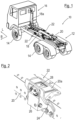
- a roll-off tipper vehicle according to the invention is shown and generally designated by the reference numeral 10, which has a vehicle body 12, three axles with corresponding wheels 14 and a driver's cab 16 in which a driver of the roll-off tipper vehicle 10 takes a seat during operation thereof.
- a handling device 18 is shown associated with the vehicle body 12, which can be hydraulically actuated to Figure 1 not shown swap bodies onto the vehicle body 12 by means of its carrying arm 18a and to set them down again therefrom, whereby the Swap body in a transport position thereof rests on support sections assigned to the base frame 20 with respective support surfaces 20a, which extend in the vehicle width direction B on both sides of the handling device 18 along the longitudinal direction L of the vehicle 10 and for reasons of clarity only in Figure 2 are designated.
- each of the support surfaces 20a is assigned in a symmetrical manner to a respective support roller unit 22, which can be actuated according to the invention to extend a corresponding pair of support rollers 28 in the vertical direction beyond the respective support surface 20a during picking up or setting down processes of swap containers in order to enable the swap container to roll off thereon.
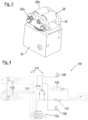
- FIG. 2 For a more detailed description of the functioning of the support roller units 22, please refer to the Figures 2 and 3 in which a support roller unit 22 is shown in an assembled and enlarged view or in a disassembled detailed view.
- the support roller unit 22 also comprises a block-shaped body 26 in which a displacement unit for displacing the two support rollers 28 is accommodated, for example a single-acting hydraulic cylinder, which is coupled via preload valves to the hydraulic circuit provided for actuating the handling device 18, as will be explained further below with reference to Fig.4 will be explained.
- the two rollers 28 are connected to a roller block 30 which can be displaced by the displacement unit mentioned, in such a way that their respective axes 28a are aligned parallel to one another and their roller surfaces 28b extend the same distance upwards in the vertical direction.
- the displacement unit can be designed in such a way that when the hydraulic pressure drops after the end of the actuation of the handling device 18, a valve for a hydraulic tank opens, so that the support roller unit 22 is displaced back into its retracted position solely by the effect of gravity or by the weight of the swap body accommodated.
- the hydraulic device 100 comprises a pressure source (not shown) which can be controlled via a control valve 102 in such a way that, as part of a work sequence for actuating the handling unit 18, two swivel cylinders 104 and a displacement cylinder 106 can be selectively controlled, which each form components of the handling unit 18.
- the swivel cylinders 104 effect the actual transfer of the swap body away from the vehicle body 12 and towards it by means of a swivel movement of the arm 18a, while the displacement cylinder 106 varies the length of the arm 18a and therefore an actuation of the displacement cylinder 106 is associated with the above-described sliding of the swap body on the support surfaces 20a.
- two preload valves 110 are provided at suitable points on the hydraulic device 100. provided, which can be set to a pressure of 120 bar, for example. Furthermore, a switchable valve 112 is provided, which opens a connection 114 to a hydraulic tank (not shown) in a pressureless state of the displacement cylinder 106 and the lifting cylinder 108 and is coupled to this via the pressure source and the control valve 102. Further connections to this tank for closing the hydraulic circuit are in Fig.4 also designated by the reference numeral 114.
Landscapes
- Engineering & Computer Science (AREA)
- Transportation (AREA)
- Mechanical Engineering (AREA)
- Forklifts And Lifting Vehicles (AREA)
- Rollers For Roller Conveyors For Transfer (AREA)
- Handcart (AREA)
Description
Die vorliegende Erfindung betrifft ein Abrollkipperfahrzeug, umfassend einen Fahrzeugkörper, eine Handhabungsvorrichtung zum Aufnehmen und Abkippen eines Wechselbehälters auf den Fahrzeugkörper und zum Absetzen des Wechselbehälters von dem Fahrzeugkörper sowie wenigstens einen Auflageabschnitt je Fahrzeugseite mit einer Auflagefläche zum Tragen des aufgenommenen Wechselbehälters.The present invention relates to a roll-off tipper vehicle comprising a vehicle body, a handling device for picking up and tipping a swap body onto the vehicle body and for setting down the swap body from the vehicle body, and at least one support section on each side of the vehicle with a support surface for supporting the picked-up swap body.
Es ist bekannt, dass bei vielen Bautypen von Abrollkipperfahrzeugen bei einem Aufnehmen eines Wechselbehälters auf den Fahrzeugkörper und auch bei einem Absetzen des Wechselbehälters von dem Fahrzeugkörper zunächst einmal ein relativ langer Verschiebeweg zurückgelegt werden muss, entlang welchem der Wechselbehälter mit dem Auflageabschnitt in Kontakt steht und über ihn abgleitet. Dies ist insbesondere bei Beginn eines Absetzvorgangs bzw. am Ende eines Aufnahmevorgangs der Fall, wenn der entsprechende Wechselbehälter beispielsweise mittels eines Verschiebezylinders der Handhabungsvorrichtung letztlich in seine endgültige aufgenommene Transportposition überführt wird oder unmittelbar aus dieser herausbewegt wird.It is known that with many types of roll-off tipper vehicles, when a swap body is picked up on the vehicle body and also when the swap body is set down from the vehicle body, a relatively long displacement path must first be covered, along which the swap body comes into contact with the support section and slides over it. This is particularly the case at the start of a setting-down process or at the end of a picking-up process, when the corresponding swap body is ultimately transferred to its final picked-up transport position, for example by means of a displacement cylinder of the handling device, or is moved directly out of this.
Hierbei hat es sich gezeigt, dass je nach Materialkombination von Wechselbehälter und Auflageabschnitt ein sogenannter "Slip-Stick-Effekt" auftreten kann, in welchem keine kontinuierliche Abgleitbewegung des Wechselbehälters an der Auflagefläche abläuft, sondern vielmehr diese Bewegung ruckweise stattfindet, d. h. mehrfach entlang des Wegs zum Stillstand kommt und dann plötzlich erneut beginnt. Hierbei kann sich das gesamte Fahrzeugsystem in einer Weise aufschaukeln, die von dem Fahrer des Fahrzeugs als unangenehm empfunden wird und zu einem erhöhten Verschleiß einzelner Komponenten davon führen kann, da beispielsweise das Fahrerhaus des Fahrzeugs in eine relativ starke Schwingung versetzt werden kann.It has been shown that, depending on the material combination of the swap body and the support section, a so-called "slip-stick effect" can occur, in which there is no continuous sliding movement of the swap body on the support surface, but rather this movement takes place in jerks, ie it comes to a standstill several times along the way and then suddenly starts again. In this case, the entire vehicle system can build up in a way that the driver of the vehicle is perceived as unpleasant and can lead to increased wear of individual components, as, for example, the driver's cab of the vehicle can be set into relatively strong vibration.
Zur Behebung dieses Problems sind nun im Stand der Technik verschiedene Maßnahmen vorgeschlagen worden, welche jedoch ihrerseits erneut Probleme hervorrufen können.To solve this problem, various measures have now been proposed in the state of the art, which, however, can in turn cause further problems.
Beispielsweise ist der Ansatz verfolgt worden, fest installierte Rollen in den Auflageabschnitten vorzusehen, über welche der entsprechende Wechselbehälter dann bei einem Aufnahme- oder Absetzvorgang davon abrollen kann. Zwar behebt diese Maßnahme zunächst einmal die oben beschriebene Problematik einer ruckweisen Bewegung des Wechselbehälters, es zeigt sich jedoch andererseits, dass insbesondere in Ausführungsformen von Abrollkipperfahrzeugen ohne hydraulische Verriegelung des Wechselbehälters in seinem aufgenommenen Transportzustand dieser beim Anfahren oder Bremsen des Fahrzeugs während des Transports des Behälters innerhalb eines gewissen Spiels nach hinten bzw. vorne rollt, da selbstverständlich die Reibung zwischen Fahrzeugkörper und Wechselbehälter durch das Vorsehen der Rollen erheblich reduziert ist. Durch die hohe Trägheit der sich hier relativ zueinander bewegenden Massen stellt eine derartige Bewegung ein erhebliches Sicherheitsrisiko dar, sodass das Vorsehen von stationären Rollen bei Abrollkipperfahrzeugen ohne hydraulische Verriegelung des Wechselbehälters im Wesentlichen ausgeschlossen ist.For example, the approach has been taken to provide permanently installed rollers in the support sections, over which the corresponding swap body can then roll off when being picked up or set down. Although this measure initially solves the problem of jerky movement of the swap body described above, it has also been shown that, particularly in roll-off tipper vehicles without hydraulic locking of the swap body in its picked-up transport state, the swap body rolls backwards or forwards within a certain amount of play when the vehicle starts or brakes during transport of the container, since the friction between the vehicle body and the swap body is of course significantly reduced by the provision of the rollers. Due to the high inertia of the masses moving relative to one another, such a movement represents a considerable safety risk, so that the provision of stationary rollers in roll-off tipper vehicles without hydraulic locking of the swap body is essentially ruled out.
Als Alternative ist vorgeschlagen worden, die Auflageabschnitte mit einem Kunststoffmaterial zu versehen, um hier verbessere Reibungseigenschaften zwischen dem entsprechenden Wechselbehälter und dem so verkleidenden Auflageabschnitt zu erzielen. Zwar kann durch diese Maßnahme der oben beschriebene "Slip-Stick-Effekt" ebenfalls erheblich reduziert werden, es zeigt sich jedoch in der Praxis, dass die hierzu verwendeten relative weichen Kunststoffprofile schnell verschleißen und somit häufig ausgetauscht werden müssen, was für Betreiber derartiger Fahrzeuge einen erheblichen Aufwand bedeutet.As an alternative, it has been suggested to cover the support sections with a plastic material in order to achieve improved friction properties between the corresponding swap body and the support section thus covered. Although this measure can also significantly reduce the "slip-stick effect" described above, it In practice, however, it has been shown that the relatively soft plastic profiles used for this purpose wear out quickly and therefore have to be replaced frequently, which represents a considerable expense for operators of such vehicles.
Für Beispiele von gattungsgemäßen Abrollkipperfahrzeugen sei insbesondere auf die
Es ist somit die Aufgabe der vorliegenden Erfindung, die oben beschriebenen Nachteile des bekannten Stands der Technik zu beheben und gleichzeitig dennoch sicherzustellen, dass Aufnahme- bzw. Absetzvorgänge von Wechselbehältern in derartigen Fahrzeugen in einer für den Fahrer angenehmen und materialschonenden Weise stattfinden.It is therefore the object of the present invention to eliminate the above-described disadvantages of the known prior art and at the same time to ensure that the picking up and setting down of swap bodies in such vehicles takes place in a manner that is pleasant for the driver and gentle on the material.
Erfindungsgemäß wird zur Lösung dieser Aufgabe vorgeschlagen, in einem Abrollkipperfahrzeug der oben beschriebenen Gattung dem wenigstens einen Auflageabschnitt wenigstens eine Tragerolleneinheit mit wenigstens einer bezüglich der Auflagefläche zwischen einer zurückgezogenen und einer ausgefahrenen Position mittels einer Verlagerungseinheit verlagerbaren Tragerolle zuzuordnen, wobei lediglich in der ausgefahrenen Position der wenigstens einen Tragerolle ein Abrollen des Wechselbehälters daran ermöglicht ist.According to the invention, to achieve this object, it is proposed to assign to the at least one support section in a roll-off tipper vehicle of the type described above at least one support roller unit with at least one support roller that can be displaced with respect to the support surface between a retracted and an extended position by means of a displacement unit, wherein the swap body can only be rolled off in the extended position of the at least one support roller.
Erfindungsgemäß wird demzufolge einerseits ein sicheres Aufliegen des Wechselbehälters auf dem Fahrzeugkörper während eines Transports davon sichergestellt, wenn die wenigstens eine verlagerbare Tragerolle in ihrer zurückgezogenen Position befindlich ist, während andererseits durch ein Ausfahren davon ein sauberes Abrollen des Behälters bei seiner Handhabung durch die Handhabungsvorrichtung ermöglicht wird.According to the invention, on the one hand, a secure resting of the swap body on the vehicle body during transport thereof is ensured when the at least one displaceable support roller is in its retracted position, while on the other hand, by extending it, a clean rolling of the container is made possible during its handling by the handling device.
Wenngleich die konkrete Positionierung der einzelnen Komponenten des Abrollkipperfahrzeugs selbstverständlich von dessen genauem Bautyp und ferner weiteren Parametern davon wie einer maximalen Tragelast oder einem maximalen Hub der Handhabungsvorrichtung abhängen können und demzufolge vom Fachmann entsprechend abstimmbar sind, so können in einer bevorzugten Ausführungsform wenigstens zwei Auflageabschnitte vorgesehen sein, welche sich in Fahrzeug-Breitenrichtung an beiden Seiten der Handhabungsvorrichtung erstrecken. Durch diese Maßnahme wird eine symmetrische Auflage für den Wechselbehälter sowohl in dessen Transportposition auf dem Fahrzeugkörper als auch bei einer Handhabung durch die Handhabungsvorrichtung geschaffen. In dieser Ausführungsform kann dann selbstverständlich jedem der Auflageabschnitte wenigstens eine Tragerolleneinheit zugeordnet sein, welche einander aus Gründen einer symmetrischen Krafteinleitung in den Fahrzeugkörper symmetrisch bezüglich der Fahrzeug-Längsrichtung in der Fahrzeug-Breitenrichtung paarweise gegenüberliegen können.Although the specific positioning of the individual components of the roll-off tipper vehicle can of course depend on its exact type and further parameters such as a maximum load or a maximum stroke of the handling device and can therefore be adjusted accordingly by a person skilled in the art, in a preferred embodiment at least two support sections can be provided which extend in the width direction of the vehicle on both sides of the handling device. This measure creates a symmetrical support for the swap body both in its transport position on the vehicle body and when handled by the handling device. In this embodiment, each of the support sections can of course be assigned at least one support roller unit, which can be arranged symmetrically in pairs opposite one another in the width direction of the vehicle with respect to the longitudinal direction of the vehicle for reasons of symmetrical force introduction into the vehicle body.
Erfindungsgemäß umfasst aus Gründen einer verbesserten Krafteinleitung bzw. Kraftaufnahme durch die wenigstens eine Tragerolleneinheit diese wenigstens zwei einzelne Tragerollen, deren Achsen parallel ausgerichtet und zueinander ortsfest sind. Demzufolge kann insbesondere ein Rollenblock vorgesehen sein, an welchem die mehreren einzelnen Tragerollen jeweils in einer drehbaren Weise an ihren beiden Enden in Halterungen aufgenommen sind, die einen integralen Teil des insgesamt verlagerbaren Blocks bilden.According to the invention, for reasons of improved force introduction or force absorption by the at least one support roller unit, said support roller unit comprises at least two individual support rollers whose axes are aligned parallel and fixed to one another. Accordingly, in particular a roller block can be provided on which the several individual support rollers are each rotatably received at their two ends in holders which form an integral part of the overall displaceable block.
Bei der Betätigungsweise der Verlagerungseinheit der wenigstens einen Tragerolleneinheit kann ferner auf unterschiedliche Alternativen zurückgegriffen werden, insbesondere könnte diese jedoch elektromechanisch, beispielsweise mittels eines Linearaktuators, oder hydraulisch über einen geeigneten Hydraulikzylinder betätigbar sein.Furthermore, different alternatives can be used for the actuation of the displacement unit of the at least one support roller unit, but in particular it could be actuated electromechanically, for example by means of a linear actuator, or hydraulically via a suitable hydraulic cylinder.
Zwar ist es selbstverständlich denkbar, den Betrieb der entsprechenden wenigstens einen Verlagerungseinheit manuell über ein entsprechendes Bedienelement auszulösen, um bei einer bevorstehenden Handhabung des Wechselbehälters zunächst einmal die wenigstens eine Tragerolle in ihre ausgefahrene Position zu überführen, in einer besonders anwenderfreundlichen Variante könnten jedoch auch Mittel zum Koordinieren des Betriebs der Handhabungsvorrichtung und der wenigstens einen Verlagerungseinheit vorgesehen sein. Demzufolge würde dann bei einer Inbetriebnahme der Handhabungsvorrichtung zum Aufnehmen oder Absetzen eines Wechselbehälters die wenigstens eine Tragerolleneinheit automatisch ebenfalls betätigt werden und die entsprechende wenigstens eine Tragerolle in ihre ausgefahrene Position überführt werden.Although it is of course conceivable to trigger the operation of the corresponding at least one displacement unit manually via a corresponding operating element in order to first of all move the at least one support roller into its extended position when handling the swap body is about to take place, in a particularly user-friendly variant, means for coordinating the operation of the handling device and the at least one displacement unit could also be provided. Consequently, when the handling device is put into operation to pick up or set down a swap body, the at least one support roller unit would then also be automatically operated and the corresponding at least one support roller would be moved into its extended position.
Wenngleich diese Mittel zum Koordinieren beispielsweise durch eine Steuereinheit ausgebildet sein können, welche insbesondere im Fall einer elektromechanisch betätigbaren Verlagerungseinheit eine entsprechende koordinierte Ansteuerung davon bewerkstelligen kann, so können in einer Variante des erfindungsgemäßen Abrollkipperfahrzeugs, in welcher sowohl die Handhabungsvorrichtung als auch die wenigstens eine Verlagerungseinheit hydraulisch betätigbar sind und mittels eines gemeinsamen Hydraulikkreises versorgt werden, die Mittel zum Koordinieren des Betriebs wenigstens ein Vorspannventil umfassen, welches bei einem Anlegen eines Hydraulikdrucks zum Betreiben der Handhabungsvorrichtung ebenfalls einen Hydraulikdruck zum Betreiben der wenigstens einen Verlagerungseinheit bereitstellt, um die entsprechende Tragerolleneinheit zu betätigen und ihre wenigstens eine Tragerolle in die ausgefahrene Position zu überführen. Diese Variante zeichnet sich durch ihren hohen Integrationsgrad und ihre günstige sowie zuverlässige Bauweise aus.Although these means for coordinating can be designed, for example, by a control unit which can carry out a corresponding coordinated control thereof, particularly in the case of an electromechanically actuated displacement unit, in a variant of the roll-off tipper vehicle according to the invention, in which both the handling device and the at least one displacement unit can be actuated hydraulically and are supplied by means of a common hydraulic circuit, the means for coordinating the operation can comprise at least one preload valve which, when a hydraulic pressure is applied to operate the handling device, also provides a hydraulic pressure to operate the at least one displacement unit in order to actuate the corresponding support roller unit and to transfer its at least one support roller into the extended position. This variant is characterized by its high degree of integration and its inexpensive and reliable design.
Hierbei kann die wenigstens eine Verlagerungseinheit dazu eingerichtet sein, in einem drucklosen Zustand einen Übergang der entsprechenden wenigstens einen Tragerolle in den zurückgezogenen Zustand durch die Wirkung der Schwerkraft zu erlauben oder mittels eines Vorspannelements hervorzurufen. Hierbei reicht dann beispielsweise ein einfach betätigbarer Hydraulikzylinder zum Verlagern der wenigstens einen Tragerolle in ihre ausgefahrenen Position aus, da das Zurücksetzen davon in die zurückgezogene Position nicht aktiv durch dieses hydraulische Element angetrieben werden muss.In this case, the at least one displacement unit can be designed to facilitate, in a pressureless state, a transition of the corresponding at least one support roller into the retracted state by the To allow the effect of gravity or to bring it about by means of a pre-tensioning element. In this case, for example, an easily operated hydraulic cylinder is sufficient to move the at least one support roller into its extended position, since the return of it into the retracted position does not have to be actively driven by this hydraulic element.
Weitere Merkmale und Vorteile der vorliegenden Erfindung werden aus der nachfolgenden Beschreibung einer Ausführungsform davon deutlich, wenn diese zusammen mit den beiliegenden Figuren betrachtet wird. Diese zeigen im Einzelnen:
- Fig. 1:
- ein erfindungsgemäßes Abrollkipperfahrzeug in einer isometrischen Ansicht von schräg hinten;
- Fig. 2:
- eine Detailansicht einer der in dem Fahrzeug aus
Figur 1 vorgesehenen Tragerolleneinheiten; - Fig. 3:
- eine weitere Detailansicht der Tragerolleneinheit aus
Figur 2 ; und - Fig. 4:
- ein schematischer Hydraulik-Schaltplan zur Ansteuerung von hydraulischen Komponenten des Abrollkipperfahrzeugs aus
Fig. 1 .
- Fig.1:
- a roll-off tipper vehicle according to the invention in an isometric view from the rear;
- Fig. 2:
- a detailed view of one of the in the vehicle from
Figure 1 intended support roller units; - Fig. 3:
- another detailed view of the support roller unit
Figure 2 ; and - Fig.4:
- a schematic hydraulic circuit diagram for controlling hydraulic components of the roll-off tipper vehicle from
Fig.1 .
In
Ferner ist dem Fahrzeugkörper 12 zugeordnet eine Handhabungsvorrichtung 18 dargestellt, welche hydraulisch dazu betätigbar ist, einen in
Ferner ist in
Für eine genauere Beschreibung der Funktionsweise der Tragerolleneinheiten 22 sei nun auf die
Hierbei sind die beiden Rollen 28 derart mit einem durch die angesprochene Verlagerungseinheit verlagerbaren Rollenblock 30 verbunden, dass ihre jeweiligen Achsen 28a parallel zueinander ausgerichtet sind und ihre Rollenflächen 28b sich in vertikaler Richtung gleich weit nach oben erstrecken. Auf diese Weise wird in der ausgefahrenen Position der Tragerolleneinheit 22 ein sauberes Abrollen des Wechselbehälters bei einer Handhabung davon sowie ein gleichmäßiger Krafteintrag in den Fahrzeugkörper 12 währenddessen gewährleistet. Insbesondere kann die Verlagerungseinheit derart ausgebildet sein, dass bei einem Absinken des Hydraulikdrucks nach dem Ende der Betätigung der Handhabungsvorrichtung 18 ein Ventil für einen Hydrauliktank öffnet, sodass die Tragerolleneinheit 22 allein durch die Wirkung der Schwerkraft bzw. durch das Gewicht des aufgenommenen Wechselbehälters zurück in ihre zurückgezogene Position verschoben wird.Here, the two
Eine beispielhafte Ausgestaltung einer Hydraulikeinrichtung 100 mit der beschriebenen Funktionsweise ist rein schematisch in
Um nun die oben beschriebene Betätigung der Komponenten der Tragerolleneinheiten 22 bildenden Hubzylinder 108 in koordinierter Weise mit einer Betätigung des Verschiebezylinders 106 zu bewirken, sind an geeigneten Stellen der Hydraulikeinrichtung 100 zwei Vorspannventile 110 vorgesehen, welche beispielsweise auf einen Druck von 120 bar eingestellt sein können. Weiterhin ist ein schaltbares Ventil 112 vorgesehen, welches in einem drucklosen Zustand des Verschiebezylinders 106 und der Hubzylinder 108 einen Anschluss 114 zu einem nicht dargestellten Hydrauliktank öffnet und hierzu über die Druckquelle und das Steuerventil 102 gekoppelt ist. Weitere Anschlüsse zu diesem Tank zum Schließen des Hydraulikkreises sind in
Claims (7)
- Roll-off tipper vehicle (10), comprising:- a vehicle body (12);- a handling device (18) for receiving a swap container on the vehicle body (12) and for removing the swap container from the vehicle body (12); and- at least one contact portion having a contact surface (20a) for carrying the received swap container;the at least one contact portion being associated with at least one conveyor roller unit (22) having at least one conveyor roller (28) that is displaceable, by means of a displacement unit, between a retracted position and an extended position, with respect to the contact surface (20a), rolling of the swap container thereon being made possible only in the extended position of the at least one conveyor roller (28), characterised in that the or at least one of the conveyor roller units (22) comprises at least two individual conveyor rollers (28), the shafts (28a) of which are oriented in parallel and so as to be fixed in position relative to one another, the conveyor rollers (28) being connected to a roller block (30), which is displaceable by the displacement unit, in such a way that the roller surfaces (28b) thereof extend upwards the same amount in the vertical direction.
- Roll-off tipper vehicle (10) according to claim 1,
characterised in that at least two contact portions are provided, which extend on both sides of the handling device (18), in the vehicle width direction (B). - Roll-off tipper vehicle (10) according to claim 2,
characterised in that each of the contact portions is associated with at least one conveyor roller unit (22), which are opposite one another in pairs in the vehicle width direction (B), in a symmetrical manner with respect to the vehicle longitudinal direction (L). - Roll-off tipper vehicle (10) according to any of the preceding claims,
characterised in that the displacement unit of the at least one conveyor roller unit (22) is electromechanically or hydraulically actuatable. - Roll-off tipper vehicle (10) according to any of the preceding claims,
characterised in that means for coordinating the operation of the handling device (18) and the at least one displacement unit are provided. - Roll-off tipper vehicle (10) according to claim 5,
characterised in that both the handling device (18) and the at least one displacement unit are hydraulically actuatable and are supplied by means of a common hydraulic circuit (100), the means for coordinating the operation being formed by at least one bias valve (110) which, in the event of application of a hydraulic pressure for operating the handling device (18), also provides a hydraulic pressure for operating the at least one displacement unit, in order to transfer the at least one conveyor roller (28) of the corresponding conveyor roller unit (22) into the extended position. - Roll-off tipper vehicle (10) according to claim 6,
characterised in that the at least one displacement unit is designed, in a pressure-free state, to allow a transition of the at least one conveyor roller (28) of the corresponding conveyor roller unit (22) into the retracted state under the action of gravity, or to bring about said transition by means of a preload element.
Applications Claiming Priority (1)
| Application Number | Priority Date | Filing Date | Title |
|---|---|---|---|
| DE102020129987.7A DE102020129987A1 (en) | 2020-11-13 | 2020-11-13 | Hook lift truck with adjustable carrying roller unit |
Publications (2)
| Publication Number | Publication Date |
|---|---|
| EP4001007A1 EP4001007A1 (en) | 2022-05-25 |
| EP4001007B1 true EP4001007B1 (en) | 2024-04-17 |
Family
ID=78463406
Family Applications (1)
| Application Number | Title | Priority Date | Filing Date |
|---|---|---|---|
| EP21204954.8A Active EP4001007B1 (en) | 2020-11-13 | 2021-10-27 | Vehicle for roll-off container with an adjustable bearing roller unit |
Country Status (4)
| Country | Link |
|---|---|
| EP (1) | EP4001007B1 (en) |
| DE (1) | DE102020129987A1 (en) |
| FI (1) | FI4001007T3 (en) |
| PL (1) | PL4001007T3 (en) |
Citations (1)
| Publication number | Priority date | Publication date | Assignee | Title |
|---|---|---|---|---|
| US5467827A (en) * | 1993-09-20 | 1995-11-21 | Mcloughlin; John E. | Modular fire truck |
Family Cites Families (5)
| Publication number | Priority date | Publication date | Assignee | Title |
|---|---|---|---|---|
| GB1570601A (en) | 1976-01-09 | 1980-07-02 | Edbro Ltd | Mechanisms for loading and unloading containers onto and from a vehicle |
| FR2358352A1 (en) | 1976-07-13 | 1978-02-10 | Bennes Marrel | STANDARD CONTAINER THAT CAN BE MANIPULATED USING A TRUCK PROVIDED WITH A HANDLING JIB |
| JPS5735134U (en) * | 1980-08-08 | 1982-02-24 | ||
| JPS59202943A (en) * | 1983-04-28 | 1984-11-16 | Shin Meiwa Ind Co Ltd | Container support device for cargo handling vehicles |
| KR20020043060A (en) * | 2000-12-01 | 2002-06-08 | 김상일 | roller device for armroll container of armroll truck |
-
2020
- 2020-11-13 DE DE102020129987.7A patent/DE102020129987A1/en active Pending
-
2021
- 2021-10-27 PL PL21204954.8T patent/PL4001007T3/en unknown
- 2021-10-27 EP EP21204954.8A patent/EP4001007B1/en active Active
- 2021-10-27 FI FIEP21204954.8T patent/FI4001007T3/en active
Patent Citations (1)
| Publication number | Priority date | Publication date | Assignee | Title |
|---|---|---|---|---|
| US5467827A (en) * | 1993-09-20 | 1995-11-21 | Mcloughlin; John E. | Modular fire truck |
Also Published As
| Publication number | Publication date |
|---|---|
| FI4001007T3 (en) | 2024-05-21 |
| PL4001007T3 (en) | 2024-07-08 |
| DE102020129987A1 (en) | 2022-05-19 |
| EP4001007A1 (en) | 2022-05-25 |
Similar Documents
| Publication | Publication Date | Title |
|---|---|---|
| DE2061043C3 (en) | Drop forging press with automatic workpiece transport | |
| EP0466065B1 (en) | Load handling vehicle | |
| EP2017020A2 (en) | Method and bending machine for compensating the deflection of components of this bending machine | |
| EP1186826B1 (en) | Lubricator for lubricating moving points | |
| EP3318431B1 (en) | Route train trailer | |
| EP0439837B1 (en) | Fork-lift truck | |
| WO2018189137A1 (en) | Pivot locking device and lifting device having a pivot locking device | |
| EP1673224A1 (en) | Movable frame parts in a printing press | |
| EP0785167A1 (en) | Side-shifting equipment for lift trucks | |
| EP1243466B1 (en) | Securing of container during transport | |
| EP1151657B1 (en) | Rotobaler for agricultural products | |
| EP2799283B1 (en) | Load transport vehicle with an interchangeable container and a lifting device for the interchangeable container | |
| EP3346155B1 (en) | Brake with brake cylinder and integrated wear adjuster | |
| DE1945312U (en) | FLOOR CONVEYOR. | |
| EP1600643B1 (en) | Control device for a hydraulic load moving device, in particular a swivel arm assembly of a lifting device for a interchangeable container on a truck. | |
| EP4001007B1 (en) | Vehicle for roll-off container with an adjustable bearing roller unit | |
| EP1673223A1 (en) | Printing units, and method for moving a frame part | |
| EP1344733B1 (en) | Transfer device for interchangeable container | |
| DE3345039A1 (en) | POSITIONING DEVICE FOR THE VEHICLES OF AN ELECTRIC RAILWAY TRACK | |
| EP2091675B1 (en) | Transfer device for a press | |
| DE19509490A1 (en) | Tilting device for a cab of a commercial vehicle | |
| EP3172958A1 (en) | Vehicle comprising a connection device for attachments | |
| EP3473580A1 (en) | Loading device | |
| DE7825062U1 (en) | LOW LIFT TRUCK | |
| DE102005022058B4 (en) | coil tongs |
Legal Events
| Date | Code | Title | Description |
|---|---|---|---|
| PUAI | Public reference made under article 153(3) epc to a published international application that has entered the european phase |
Free format text: ORIGINAL CODE: 0009012 |
|
| STAA | Information on the status of an ep patent application or granted ep patent |
Free format text: STATUS: THE APPLICATION HAS BEEN PUBLISHED |
|
| AK | Designated contracting states |
Kind code of ref document: A1 Designated state(s): AL AT BE BG CH CY CZ DE DK EE ES FI FR GB GR HR HU IE IS IT LI LT LU LV MC MK MT NL NO PL PT RO RS SE SI SK SM TR |
|
| STAA | Information on the status of an ep patent application or granted ep patent |
Free format text: STATUS: REQUEST FOR EXAMINATION WAS MADE |
|
| 17P | Request for examination filed |
Effective date: 20221011 |
|
| RBV | Designated contracting states (corrected) |
Designated state(s): AL AT BE BG CH CY CZ DE DK EE ES FI FR GB GR HR HU IE IS IT LI LT LU LV MC MK MT NL NO PL PT RO RS SE SI SK SM TR |
|
| GRAP | Despatch of communication of intention to grant a patent |
Free format text: ORIGINAL CODE: EPIDOSNIGR1 |
|
| STAA | Information on the status of an ep patent application or granted ep patent |
Free format text: STATUS: GRANT OF PATENT IS INTENDED |
|
| INTG | Intention to grant announced |
Effective date: 20231107 |
|
| RAP3 | Party data changed (applicant data changed or rights of an application transferred) |
Owner name: FRANZ XAVER MEILLER FAHRZEUG- UND MASCHINENFABRIK-GMBH & CO. KG |
|
| GRAS | Grant fee paid |
Free format text: ORIGINAL CODE: EPIDOSNIGR3 |
|
| GRAA | (expected) grant |
Free format text: ORIGINAL CODE: 0009210 |
|
| STAA | Information on the status of an ep patent application or granted ep patent |
Free format text: STATUS: THE PATENT HAS BEEN GRANTED |
|
| AK | Designated contracting states |
Kind code of ref document: B1 Designated state(s): AL AT BE BG CH CY CZ DE DK EE ES FI FR GB GR HR HU IE IS IT LI LT LU LV MC MK MT NL NO PL PT RO RS SE SI SK SM TR |
|
| REG | Reference to a national code |
Ref country code: GB Ref legal event code: FG4D Free format text: NOT ENGLISH |
|
| REG | Reference to a national code |
Ref country code: CH Ref legal event code: EP |
|
| REG | Reference to a national code |
Ref country code: DE Ref legal event code: R096 Ref document number: 502021003372 Country of ref document: DE |
|
| REG | Reference to a national code |
Ref country code: IE Ref legal event code: FG4D Free format text: LANGUAGE OF EP DOCUMENT: GERMAN |
|
| REG | Reference to a national code |
Ref country code: FI Ref legal event code: FGE |
|
| REG | Reference to a national code |
Ref country code: NL Ref legal event code: FP |
|
| REG | Reference to a national code |
Ref country code: LT Ref legal event code: MG9D |
|
| PG25 | Lapsed in a contracting state [announced via postgrant information from national office to epo] |
Ref country code: IS Free format text: LAPSE BECAUSE OF FAILURE TO SUBMIT A TRANSLATION OF THE DESCRIPTION OR TO PAY THE FEE WITHIN THE PRESCRIBED TIME-LIMIT Effective date: 20240817 |
|
| PG25 | Lapsed in a contracting state [announced via postgrant information from national office to epo] |
Ref country code: BG Free format text: LAPSE BECAUSE OF FAILURE TO SUBMIT A TRANSLATION OF THE DESCRIPTION OR TO PAY THE FEE WITHIN THE PRESCRIBED TIME-LIMIT Effective date: 20240417 |
|
| PG25 | Lapsed in a contracting state [announced via postgrant information from national office to epo] |
Ref country code: HR Free format text: LAPSE BECAUSE OF FAILURE TO SUBMIT A TRANSLATION OF THE DESCRIPTION OR TO PAY THE FEE WITHIN THE PRESCRIBED TIME-LIMIT Effective date: 20240417 |
|
| PG25 | Lapsed in a contracting state [announced via postgrant information from national office to epo] |
Ref country code: GR Free format text: LAPSE BECAUSE OF FAILURE TO SUBMIT A TRANSLATION OF THE DESCRIPTION OR TO PAY THE FEE WITHIN THE PRESCRIBED TIME-LIMIT Effective date: 20240718 |
|
| PG25 | Lapsed in a contracting state [announced via postgrant information from national office to epo] |
Ref country code: PT Free format text: LAPSE BECAUSE OF FAILURE TO SUBMIT A TRANSLATION OF THE DESCRIPTION OR TO PAY THE FEE WITHIN THE PRESCRIBED TIME-LIMIT Effective date: 20240819 |
|
| PG25 | Lapsed in a contracting state [announced via postgrant information from national office to epo] |
Ref country code: ES Free format text: LAPSE BECAUSE OF FAILURE TO SUBMIT A TRANSLATION OF THE DESCRIPTION OR TO PAY THE FEE WITHIN THE PRESCRIBED TIME-LIMIT Effective date: 20240417 |
|
| PG25 | Lapsed in a contracting state [announced via postgrant information from national office to epo] |
Ref country code: LV Free format text: LAPSE BECAUSE OF FAILURE TO SUBMIT A TRANSLATION OF THE DESCRIPTION OR TO PAY THE FEE WITHIN THE PRESCRIBED TIME-LIMIT Effective date: 20240417 |
|
| PG25 | Lapsed in a contracting state [announced via postgrant information from national office to epo] |
Ref country code: PT Free format text: LAPSE BECAUSE OF FAILURE TO SUBMIT A TRANSLATION OF THE DESCRIPTION OR TO PAY THE FEE WITHIN THE PRESCRIBED TIME-LIMIT Effective date: 20240819 Ref country code: NO Free format text: LAPSE BECAUSE OF FAILURE TO SUBMIT A TRANSLATION OF THE DESCRIPTION OR TO PAY THE FEE WITHIN THE PRESCRIBED TIME-LIMIT Effective date: 20240717 Ref country code: LV Free format text: LAPSE BECAUSE OF FAILURE TO SUBMIT A TRANSLATION OF THE DESCRIPTION OR TO PAY THE FEE WITHIN THE PRESCRIBED TIME-LIMIT Effective date: 20240417 Ref country code: IS Free format text: LAPSE BECAUSE OF FAILURE TO SUBMIT A TRANSLATION OF THE DESCRIPTION OR TO PAY THE FEE WITHIN THE PRESCRIBED TIME-LIMIT Effective date: 20240817 Ref country code: HR Free format text: LAPSE BECAUSE OF FAILURE TO SUBMIT A TRANSLATION OF THE DESCRIPTION OR TO PAY THE FEE WITHIN THE PRESCRIBED TIME-LIMIT Effective date: 20240417 Ref country code: GR Free format text: LAPSE BECAUSE OF FAILURE TO SUBMIT A TRANSLATION OF THE DESCRIPTION OR TO PAY THE FEE WITHIN THE PRESCRIBED TIME-LIMIT Effective date: 20240718 Ref country code: ES Free format text: LAPSE BECAUSE OF FAILURE TO SUBMIT A TRANSLATION OF THE DESCRIPTION OR TO PAY THE FEE WITHIN THE PRESCRIBED TIME-LIMIT Effective date: 20240417 Ref country code: BG Free format text: LAPSE BECAUSE OF FAILURE TO SUBMIT A TRANSLATION OF THE DESCRIPTION OR TO PAY THE FEE WITHIN THE PRESCRIBED TIME-LIMIT Effective date: 20240417 Ref country code: RS Free format text: LAPSE BECAUSE OF FAILURE TO SUBMIT A TRANSLATION OF THE DESCRIPTION OR TO PAY THE FEE WITHIN THE PRESCRIBED TIME-LIMIT Effective date: 20240717 |
|
| PG25 | Lapsed in a contracting state [announced via postgrant information from national office to epo] |
Ref country code: DK Free format text: LAPSE BECAUSE OF FAILURE TO SUBMIT A TRANSLATION OF THE DESCRIPTION OR TO PAY THE FEE WITHIN THE PRESCRIBED TIME-LIMIT Effective date: 20240417 |
|
| REG | Reference to a national code |
Ref country code: DE Ref legal event code: R097 Ref document number: 502021003372 Country of ref document: DE |
|
| PG25 | Lapsed in a contracting state [announced via postgrant information from national office to epo] |
Ref country code: EE Free format text: LAPSE BECAUSE OF FAILURE TO SUBMIT A TRANSLATION OF THE DESCRIPTION OR TO PAY THE FEE WITHIN THE PRESCRIBED TIME-LIMIT Effective date: 20240417 |
|
| PG25 | Lapsed in a contracting state [announced via postgrant information from national office to epo] |
Ref country code: CZ Free format text: LAPSE BECAUSE OF FAILURE TO SUBMIT A TRANSLATION OF THE DESCRIPTION OR TO PAY THE FEE WITHIN THE PRESCRIBED TIME-LIMIT Effective date: 20240417 |
|
| PG25 | Lapsed in a contracting state [announced via postgrant information from national office to epo] |
Ref country code: SK Free format text: LAPSE BECAUSE OF FAILURE TO SUBMIT A TRANSLATION OF THE DESCRIPTION OR TO PAY THE FEE WITHIN THE PRESCRIBED TIME-LIMIT Effective date: 20240417 Ref country code: RO Free format text: LAPSE BECAUSE OF FAILURE TO SUBMIT A TRANSLATION OF THE DESCRIPTION OR TO PAY THE FEE WITHIN THE PRESCRIBED TIME-LIMIT Effective date: 20240417 |
|
| PG25 | Lapsed in a contracting state [announced via postgrant information from national office to epo] |
Ref country code: SM Free format text: LAPSE BECAUSE OF FAILURE TO SUBMIT A TRANSLATION OF THE DESCRIPTION OR TO PAY THE FEE WITHIN THE PRESCRIBED TIME-LIMIT Effective date: 20240417 |
|
| PG25 | Lapsed in a contracting state [announced via postgrant information from national office to epo] |
Ref country code: SM Free format text: LAPSE BECAUSE OF FAILURE TO SUBMIT A TRANSLATION OF THE DESCRIPTION OR TO PAY THE FEE WITHIN THE PRESCRIBED TIME-LIMIT Effective date: 20240417 Ref country code: SK Free format text: LAPSE BECAUSE OF FAILURE TO SUBMIT A TRANSLATION OF THE DESCRIPTION OR TO PAY THE FEE WITHIN THE PRESCRIBED TIME-LIMIT Effective date: 20240417 Ref country code: RO Free format text: LAPSE BECAUSE OF FAILURE TO SUBMIT A TRANSLATION OF THE DESCRIPTION OR TO PAY THE FEE WITHIN THE PRESCRIBED TIME-LIMIT Effective date: 20240417 Ref country code: EE Free format text: LAPSE BECAUSE OF FAILURE TO SUBMIT A TRANSLATION OF THE DESCRIPTION OR TO PAY THE FEE WITHIN THE PRESCRIBED TIME-LIMIT Effective date: 20240417 Ref country code: DK Free format text: LAPSE BECAUSE OF FAILURE TO SUBMIT A TRANSLATION OF THE DESCRIPTION OR TO PAY THE FEE WITHIN THE PRESCRIBED TIME-LIMIT Effective date: 20240417 Ref country code: CZ Free format text: LAPSE BECAUSE OF FAILURE TO SUBMIT A TRANSLATION OF THE DESCRIPTION OR TO PAY THE FEE WITHIN THE PRESCRIBED TIME-LIMIT Effective date: 20240417 |
|
| PG25 | Lapsed in a contracting state [announced via postgrant information from national office to epo] |
Ref country code: IT Free format text: LAPSE BECAUSE OF FAILURE TO SUBMIT A TRANSLATION OF THE DESCRIPTION OR TO PAY THE FEE WITHIN THE PRESCRIBED TIME-LIMIT Effective date: 20240417 |
|
| PLBE | No opposition filed within time limit |
Free format text: ORIGINAL CODE: 0009261 |
|
| STAA | Information on the status of an ep patent application or granted ep patent |
Free format text: STATUS: NO OPPOSITION FILED WITHIN TIME LIMIT |
|
| 26N | No opposition filed |
Effective date: 20250120 |
|
| PG25 | Lapsed in a contracting state [announced via postgrant information from national office to epo] |
Ref country code: SI Free format text: LAPSE BECAUSE OF FAILURE TO SUBMIT A TRANSLATION OF THE DESCRIPTION OR TO PAY THE FEE WITHIN THE PRESCRIBED TIME-LIMIT Effective date: 20240417 |
|
| REG | Reference to a national code |
Ref country code: CH Ref legal event code: PL |
|
| PG25 | Lapsed in a contracting state [announced via postgrant information from national office to epo] |
Ref country code: MC Free format text: LAPSE BECAUSE OF FAILURE TO SUBMIT A TRANSLATION OF THE DESCRIPTION OR TO PAY THE FEE WITHIN THE PRESCRIBED TIME-LIMIT Effective date: 20240417 |
|
| PG25 | Lapsed in a contracting state [announced via postgrant information from national office to epo] |
Ref country code: LU Free format text: LAPSE BECAUSE OF NON-PAYMENT OF DUE FEES Effective date: 20241027 Ref country code: BE Free format text: LAPSE BECAUSE OF NON-PAYMENT OF DUE FEES Effective date: 20241031 |
|
| PG25 | Lapsed in a contracting state [announced via postgrant information from national office to epo] |
Ref country code: CH Free format text: LAPSE BECAUSE OF NON-PAYMENT OF DUE FEES Effective date: 20241031 |
|
| REG | Reference to a national code |
Ref country code: BE Ref legal event code: MM Effective date: 20241031 |
|
| PG25 | Lapsed in a contracting state [announced via postgrant information from national office to epo] |
Ref country code: SE Free format text: LAPSE BECAUSE OF FAILURE TO SUBMIT A TRANSLATION OF THE DESCRIPTION OR TO PAY THE FEE WITHIN THE PRESCRIBED TIME-LIMIT Effective date: 20240417 |
|
| PG25 | Lapsed in a contracting state [announced via postgrant information from national office to epo] |
Ref country code: IE Free format text: LAPSE BECAUSE OF NON-PAYMENT OF DUE FEES Effective date: 20241027 |
|
| PGFP | Annual fee paid to national office [announced via postgrant information from national office to epo] |
Ref country code: NL Payment date: 20251021 Year of fee payment: 5 |
|
| PGFP | Annual fee paid to national office [announced via postgrant information from national office to epo] |
Ref country code: DE Payment date: 20250929 Year of fee payment: 5 |
|
| PGFP | Annual fee paid to national office [announced via postgrant information from national office to epo] |
Ref country code: AT Payment date: 20260113 Year of fee payment: 5 |
|
| PGFP | Annual fee paid to national office [announced via postgrant information from national office to epo] |
Ref country code: FI Payment date: 20251028 Year of fee payment: 5 |
|
| PGFP | Annual fee paid to national office [announced via postgrant information from national office to epo] |
Ref country code: FR Payment date: 20251030 Year of fee payment: 5 |
|
| PGFP | Annual fee paid to national office [announced via postgrant information from national office to epo] |
Ref country code: PL Payment date: 20251017 Year of fee payment: 5 |
|
| PG25 | Lapsed in a contracting state [announced via postgrant information from national office to epo] |
Ref country code: CY Free format text: LAPSE BECAUSE OF FAILURE TO SUBMIT A TRANSLATION OF THE DESCRIPTION OR TO PAY THE FEE WITHIN THE PRESCRIBED TIME-LIMIT; INVALID AB INITIO Effective date: 20211027 |
|
| PG25 | Lapsed in a contracting state [announced via postgrant information from national office to epo] |
Ref country code: HU Free format text: LAPSE BECAUSE OF FAILURE TO SUBMIT A TRANSLATION OF THE DESCRIPTION OR TO PAY THE FEE WITHIN THE PRESCRIBED TIME-LIMIT; INVALID AB INITIO Effective date: 20211027 |