EP4000961A1 - Reifen - Google Patents
Reifen Download PDFInfo
- Publication number
- EP4000961A1 EP4000961A1 EP21201033.4A EP21201033A EP4000961A1 EP 4000961 A1 EP4000961 A1 EP 4000961A1 EP 21201033 A EP21201033 A EP 21201033A EP 4000961 A1 EP4000961 A1 EP 4000961A1
- Authority
- EP
- European Patent Office
- Prior art keywords
- shoulder
- tyre
- land portion
- lateral grooves
- pair
- Prior art date
- Legal status (The legal status is an assumption and is not a legal conclusion. Google has not performed a legal analysis and makes no representation as to the accuracy of the status listed.)
- Granted
Links
- 238000012360 testing method Methods 0.000 description 11
- 230000000052 comparative effect Effects 0.000 description 7
- 238000011161 development Methods 0.000 description 3
- 230000007246 mechanism Effects 0.000 description 3
- 230000008859 change Effects 0.000 description 2
- 230000000694 effects Effects 0.000 description 2
- 230000009471 action Effects 0.000 description 1
- 230000008901 benefit Effects 0.000 description 1
- 238000013461 design Methods 0.000 description 1
- 238000006073 displacement reaction Methods 0.000 description 1
- 230000006872 improvement Effects 0.000 description 1
- 238000011056 performance test Methods 0.000 description 1
- 238000013112 stability test Methods 0.000 description 1
- 238000010998 test method Methods 0.000 description 1
Images


Classifications
-
- B—PERFORMING OPERATIONS; TRANSPORTING
- B60—VEHICLES IN GENERAL
- B60C—VEHICLE TYRES; TYRE INFLATION; TYRE CHANGING; CONNECTING VALVES TO INFLATABLE ELASTIC BODIES IN GENERAL; DEVICES OR ARRANGEMENTS RELATED TO TYRES
- B60C11/00—Tyre tread bands; Tread patterns; Anti-skid inserts
- B60C11/03—Tread patterns
- B60C11/0304—Asymmetric patterns
-
- B—PERFORMING OPERATIONS; TRANSPORTING
- B60—VEHICLES IN GENERAL
- B60C—VEHICLE TYRES; TYRE INFLATION; TYRE CHANGING; CONNECTING VALVES TO INFLATABLE ELASTIC BODIES IN GENERAL; DEVICES OR ARRANGEMENTS RELATED TO TYRES
- B60C11/00—Tyre tread bands; Tread patterns; Anti-skid inserts
- B60C11/03—Tread patterns
- B60C11/0302—Tread patterns directional pattern, i.e. with main rolling direction
-
- B—PERFORMING OPERATIONS; TRANSPORTING
- B60—VEHICLES IN GENERAL
- B60C—VEHICLE TYRES; TYRE INFLATION; TYRE CHANGING; CONNECTING VALVES TO INFLATABLE ELASTIC BODIES IN GENERAL; DEVICES OR ARRANGEMENTS RELATED TO TYRES
- B60C11/00—Tyre tread bands; Tread patterns; Anti-skid inserts
- B60C11/01—Shape of the shoulders between tread and sidewall, e.g. rounded, stepped or cantilevered
-
- B—PERFORMING OPERATIONS; TRANSPORTING
- B60—VEHICLES IN GENERAL
- B60C—VEHICLE TYRES; TYRE INFLATION; TYRE CHANGING; CONNECTING VALVES TO INFLATABLE ELASTIC BODIES IN GENERAL; DEVICES OR ARRANGEMENTS RELATED TO TYRES
- B60C11/00—Tyre tread bands; Tread patterns; Anti-skid inserts
- B60C11/03—Tread patterns
- B60C11/0306—Patterns comprising block rows or discontinuous ribs
-
- B—PERFORMING OPERATIONS; TRANSPORTING
- B60—VEHICLES IN GENERAL
- B60C—VEHICLE TYRES; TYRE INFLATION; TYRE CHANGING; CONNECTING VALVES TO INFLATABLE ELASTIC BODIES IN GENERAL; DEVICES OR ARRANGEMENTS RELATED TO TYRES
- B60C11/00—Tyre tread bands; Tread patterns; Anti-skid inserts
- B60C11/03—Tread patterns
- B60C11/032—Patterns comprising isolated recesses
- B60C11/0323—Patterns comprising isolated recesses tread comprising channels under the tread surface, e.g. for draining water
-
- B—PERFORMING OPERATIONS; TRANSPORTING
- B60—VEHICLES IN GENERAL
- B60C—VEHICLE TYRES; TYRE INFLATION; TYRE CHANGING; CONNECTING VALVES TO INFLATABLE ELASTIC BODIES IN GENERAL; DEVICES OR ARRANGEMENTS RELATED TO TYRES
- B60C11/00—Tyre tread bands; Tread patterns; Anti-skid inserts
- B60C11/03—Tread patterns
- B60C11/12—Tread patterns characterised by the use of narrow slits or incisions, e.g. sipes
- B60C11/1236—Tread patterns characterised by the use of narrow slits or incisions, e.g. sipes with special arrangements in the tread pattern
- B60C11/125—Tread patterns characterised by the use of narrow slits or incisions, e.g. sipes with special arrangements in the tread pattern arranged at the groove bottom
-
- B—PERFORMING OPERATIONS; TRANSPORTING
- B60—VEHICLES IN GENERAL
- B60C—VEHICLE TYRES; TYRE INFLATION; TYRE CHANGING; CONNECTING VALVES TO INFLATABLE ELASTIC BODIES IN GENERAL; DEVICES OR ARRANGEMENTS RELATED TO TYRES
- B60C11/00—Tyre tread bands; Tread patterns; Anti-skid inserts
- B60C11/03—Tread patterns
- B60C11/13—Tread patterns characterised by the groove cross-section, e.g. for buttressing or preventing stone-trapping
- B60C11/1307—Tread patterns characterised by the groove cross-section, e.g. for buttressing or preventing stone-trapping with special features of the groove walls
-
- B—PERFORMING OPERATIONS; TRANSPORTING
- B60—VEHICLES IN GENERAL
- B60C—VEHICLE TYRES; TYRE INFLATION; TYRE CHANGING; CONNECTING VALVES TO INFLATABLE ELASTIC BODIES IN GENERAL; DEVICES OR ARRANGEMENTS RELATED TO TYRES
- B60C11/00—Tyre tread bands; Tread patterns; Anti-skid inserts
- B60C11/03—Tread patterns
- B60C11/13—Tread patterns characterised by the groove cross-section, e.g. for buttressing or preventing stone-trapping
- B60C11/1369—Tie bars for linking block elements and bridging the groove
-
- B—PERFORMING OPERATIONS; TRANSPORTING
- B60—VEHICLES IN GENERAL
- B60C—VEHICLE TYRES; TYRE INFLATION; TYRE CHANGING; CONNECTING VALVES TO INFLATABLE ELASTIC BODIES IN GENERAL; DEVICES OR ARRANGEMENTS RELATED TO TYRES
- B60C11/00—Tyre tread bands; Tread patterns; Anti-skid inserts
- B60C11/03—Tread patterns
- B60C11/13—Tread patterns characterised by the groove cross-section, e.g. for buttressing or preventing stone-trapping
- B60C11/1376—Three dimensional block surfaces departing from the enveloping tread contour
- B60C11/1392—Three dimensional block surfaces departing from the enveloping tread contour with chamfered block edges
-
- B—PERFORMING OPERATIONS; TRANSPORTING
- B60—VEHICLES IN GENERAL
- B60C—VEHICLE TYRES; TYRE INFLATION; TYRE CHANGING; CONNECTING VALVES TO INFLATABLE ELASTIC BODIES IN GENERAL; DEVICES OR ARRANGEMENTS RELATED TO TYRES
- B60C11/00—Tyre tread bands; Tread patterns; Anti-skid inserts
- B60C11/03—Tread patterns
- B60C11/0318—Tread patterns irregular patterns with particular pitch sequence
-
- B—PERFORMING OPERATIONS; TRANSPORTING
- B60—VEHICLES IN GENERAL
- B60C—VEHICLE TYRES; TYRE INFLATION; TYRE CHANGING; CONNECTING VALVES TO INFLATABLE ELASTIC BODIES IN GENERAL; DEVICES OR ARRANGEMENTS RELATED TO TYRES
- B60C11/00—Tyre tread bands; Tread patterns; Anti-skid inserts
- B60C11/03—Tread patterns
- B60C11/0327—Tread patterns characterised by special properties of the tread pattern
- B60C11/033—Tread patterns characterised by special properties of the tread pattern by the void or net-to-gross ratios of the patterns
-
- B—PERFORMING OPERATIONS; TRANSPORTING
- B60—VEHICLES IN GENERAL
- B60C—VEHICLE TYRES; TYRE INFLATION; TYRE CHANGING; CONNECTING VALVES TO INFLATABLE ELASTIC BODIES IN GENERAL; DEVICES OR ARRANGEMENTS RELATED TO TYRES
- B60C11/00—Tyre tread bands; Tread patterns; Anti-skid inserts
- B60C11/01—Shape of the shoulders between tread and sidewall, e.g. rounded, stepped or cantilevered
- B60C2011/013—Shape of the shoulders between tread and sidewall, e.g. rounded, stepped or cantilevered provided with a recessed portion
-
- B—PERFORMING OPERATIONS; TRANSPORTING
- B60—VEHICLES IN GENERAL
- B60C—VEHICLE TYRES; TYRE INFLATION; TYRE CHANGING; CONNECTING VALVES TO INFLATABLE ELASTIC BODIES IN GENERAL; DEVICES OR ARRANGEMENTS RELATED TO TYRES
- B60C11/00—Tyre tread bands; Tread patterns; Anti-skid inserts
- B60C11/03—Tread patterns
- B60C2011/0337—Tread patterns characterised by particular design features of the pattern
- B60C2011/0339—Grooves
- B60C2011/0341—Circumferential grooves
- B60C2011/0348—Narrow grooves, i.e. having a width of less than 4 mm
-
- B—PERFORMING OPERATIONS; TRANSPORTING
- B60—VEHICLES IN GENERAL
- B60C—VEHICLE TYRES; TYRE INFLATION; TYRE CHANGING; CONNECTING VALVES TO INFLATABLE ELASTIC BODIES IN GENERAL; DEVICES OR ARRANGEMENTS RELATED TO TYRES
- B60C11/00—Tyre tread bands; Tread patterns; Anti-skid inserts
- B60C11/03—Tread patterns
- B60C2011/0337—Tread patterns characterised by particular design features of the pattern
- B60C2011/0339—Grooves
- B60C2011/0381—Blind or isolated grooves
- B60C2011/0383—Blind or isolated grooves at the centre of the tread
-
- B—PERFORMING OPERATIONS; TRANSPORTING
- B60—VEHICLES IN GENERAL
- B60C—VEHICLE TYRES; TYRE INFLATION; TYRE CHANGING; CONNECTING VALVES TO INFLATABLE ELASTIC BODIES IN GENERAL; DEVICES OR ARRANGEMENTS RELATED TO TYRES
- B60C11/00—Tyre tread bands; Tread patterns; Anti-skid inserts
- B60C11/03—Tread patterns
- B60C2011/0337—Tread patterns characterised by particular design features of the pattern
- B60C2011/0386—Continuous ribs
- B60C2011/0388—Continuous ribs provided at the equatorial plane
-
- B—PERFORMING OPERATIONS; TRANSPORTING
- B60—VEHICLES IN GENERAL
- B60C—VEHICLE TYRES; TYRE INFLATION; TYRE CHANGING; CONNECTING VALVES TO INFLATABLE ELASTIC BODIES IN GENERAL; DEVICES OR ARRANGEMENTS RELATED TO TYRES
- B60C11/00—Tyre tread bands; Tread patterns; Anti-skid inserts
- B60C11/03—Tread patterns
- B60C11/12—Tread patterns characterised by the use of narrow slits or incisions, e.g. sipes
- B60C11/1204—Tread patterns characterised by the use of narrow slits or incisions, e.g. sipes with special shape of the sipe
- B60C2011/1209—Tread patterns characterised by the use of narrow slits or incisions, e.g. sipes with special shape of the sipe straight at the tread surface
Definitions
- the present disclosure relates to a tyre.
- the patent document 1 discloses a pneumatic tyre with a tread portion having a designated mounting direction to a vehicle, the tread portion being provided with outer shoulder lateral grooves and inner shoulder lateral grooves.
- the intersections of the groove edges of the outer shoulder lateral grooves and the outboard tread edge, and the intersections of the groove edges of the inner shoulder lateral grooves and the inboard tread edge are provided at different positions in the tyre circumferential direction.
- Patent document 1 Japanese Unexamined Patent Application Publication 2018-140745
- H&T wear heel-and-toe wear
- the present disclosure has been made in view of the above circumstances and has a major object to provide a tyre capable of preventing uneven wear such as H&T wear.
- a tyre includes a tread portion including axially spaced first and second tread edges that are axially outermost edges of a ground contacting patch of the tyre which occurs under a condition such that a 70% standard tyre load is applied to the tyre placed under a normal state, wherein the normal state is such that the tyre is mounted onto a standard wheel rim and inflated to a standard pressure, a first shoulder land portion including the first tread edge, and a first shoulder circumferential groove located inwardly in a tyre axial direction of and adjacent to the first shoulder land portion and extending continuously in a tyre circumferential direction, wherein the first shoulder land portion is provided with a plurality of first shoulder lateral grooves extending from the first shoulder circumferential groove across the first tread edge, each of the plurality of first shoulder lateral grooves has a pair of first groove walls, and the pair of first groove walls is provided with a pair of first chamfer portions that extends from
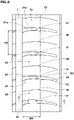
- FIG. 1 is a development view of a tread portion 2 of a tyre 1 according to an embodiment.
- the tyre 1 according to the present embodiment for example, is a pneumatic passenger car tyre, especially being a summer tyre.
- the present disclosure is not limited to such an aspect and may be used for all-season tyre, heavy-duty tyre, and the like.
- the tyre 1 includes the tread portion 2 having a designated mounting direction to a vehicle.
- the mounting direction to a vehicle is indicated by characters or marks on the sidewall portion, etc. (not shown), for example.
- the tread portion 2 for example, has an asymmetric pattern (i.e., the tread pattern being not line-symmetrical with respect to the tyre equator C).
- the tyre 1 may be mounted on a vehicle in an unspecified direction, and the tread portion 2 may be configured as a symmetrical pattern.
- the tread portion 2 includes axially spaced first tread edge T1 and second tread edge T2.
- the tread portion 2 according to the present embodiment has a designated mounting direction to a vehicle such that the first tread edge T1 is located on the outside of a vehicle when mounted on the vehicle and the second tread edge T2 is located on the inside of the vehicle when mounted on the vehicle.
- the first tread edge T1 and the second tread edge T2 are axially outermost edges of a ground contacting patch of the tyre which occurs under a condition such that the tyre 1 placed under a normal state is grounded on a plane with a 70% standard tyre load at zero camber angles.
- the first tread edge T1 and the second tread edge T2 are close to the actual ground contact edges of the tread portion 2 when a vehicle is being stopped or traveling straight at a constant speed.
- the area located axially inwardly of the first and second tread edges T1 and T2 is always in contact with the ground unless the ground contact pressure becomes excessively low.
- areas around the first tread edge T1 and the second tread edge T2 tend to have a large change in ground contact pressure.
- the "normal state" is such that the tyre 1 is mounted onto a standard wheel rim with a standard pressure but loaded with no tyre load. Unless otherwise noted, dimensions of portions of the tyre 1 are values measured under the normal state. If a tyre is not based on the standards, or is a non-pneumatic tyre, the normal state is a standard state of use according to the purpose of use of the tyre, and means a state of no load. As used herein, unless otherwise noted, dimensions of portions of the tyre 1 are values measured under the normal state.
- the "standard wheel rim” is a wheel rim officially approved for each tyre by standards organizations on which the tyre is based, wherein the standard wheel rim is the "standard rim” specified in JATMA, the "Design Rim” in TRA, and the “Measuring Rim” in ETRTO, for example.
- the "standard pressure” is a standard pressure officially approved for each tyre by standards organizations on which the tyre is based, wherein the standard pressure is the "maximum air pressure” in JATMA, the maximum pressure given in the "Tire Load Limits at Various Cold Inflation Pressures” table in TRA, and the “Inflation Pressure” in ETRTO, for example.
- the "standard tyre load” is a tyre load officially approved for each tyre by standards organizations in which the tyre is based, wherein the standard tyre load is the "maximum load capacity" in JATMA, the maximum value given in the above-mentioned table in TRA, and the “Load Capacity” in ETRTO, for example. If a tyre is not based on the standards, or is a non-pneumatic tyre, the standard tyre load refers to the load acting on the tyre when the tyre is under a standard mounting state.
- the "standard mounting state” refers to a state in which the tyre is mounted on a standard vehicle according to the purpose of use of the tyre, and the vehicle is stationary on a flat road surface while being able to run.
- the tread portion 2 includes a plurality of circumferential grooves 3 extending continuously in the tyre circumferential direction between the first tread edge T1 and the second tread edge T2, and a plurality of land portions divided by the circumferential grooves 3.
- the tyre 1 according to the present embodiment is configured as a so-called five-rib tyre in which the tread portion 2 has five ribs divided by four circumferential grooves 3. Note that the present disclosure is not limited to such an aspect, and the tyre may be configured as a so-called four-rib tyre in which the tread portion 2 has four ribs divided by three circumferential grooves 3, for example.
- the circumferential grooves 3 include a first crown circumferential groove 4, a second crown circumferential groove 5, a first shoulder circumferential groove 6 and a second shoulder circumferential groove 7.
- the first crown circumferential groove 4 and the second crown circumferential groove 5 are disposed such that the tyre, heavy tyre equator C is arranged therebetween.
- the first shoulder circumferential groove 6 is disposed between the first crown circumferential groove 4 and the first tread edge T1.
- the second shoulder circumferential groove 7 is disposed between the second crown circumferential groove 5 and the second tread edge T2.
- the circumferential grooves 3 extend straight in the tyre circumferential direction.
- the circumferential grooves 3 may extend in a zigzag manner.
- a distance L1 in the tyre axial direction from the tyre equator C to the first crown circumferential groove 4 or the second crown circumferential groove 5 is in a range of from 5% to 15% of the tread width TW, for example.
- a distance L2 in the tyre axial direction from the tyre equator C to the first shoulder circumferential groove 6 or the second shoulder circumferential groove 7 is in a range of from 25% to 35% of the tread width TW, for example.
- the tread width TW is a distance in the tyre axial direction from the first tread edge T1 to the second tread edge T2 under the normal state.
- a groove width W1 of the circumferential grooves 3 is at least 3 mm. In some preferred embodiments, the groove width W1 of the circumferential grooves 3 is in a range of 2.0% to 6.0% of the tread width TW.
- the land portions at least, include a first shoulder land portion 11 including the first tread edge T1.
- the land portions according to the present embodiment include a second shoulder land portion 12 including the second tread edge T2.
- the land portions according to the present embodiment include a crown land portion 15, a first middle land portion 13 and a second middle land portion 14.
- the crown land portion 15 is defined between the first crown circumferential groove 4 and the second crown circumferential groove 5.
- the first middle land portion 13 is defined between the first crown circumferential groove 4 and the first shoulder circumferential groove 6.
- the second middle land portion 14 is defined between the second crown circumferential groove 5 and the second shoulder circumferential groove 7.
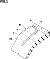
- FIG. 2 is a partial enlarged perspective view of the first shoulder land portion 11 of FIG. 1 .
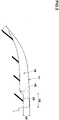
- FIG. 3 is a partial enlarged view of the first shoulder land portion 11 of FIG. 1 .
- the first shoulder land portion 11 is provided with a plurality of first shoulder lateral grooves 16 extending from the first shoulder circumferential groove 6 across the first tread edge T1.
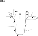
- FIG. 4 is a cross-sectional view taken along the line A-A of FIG. 3 .
- each first shoulder lateral groove 16 has a pair of first groove walls 17.
- the pair of first groove walls 17 is provided with a pair of first chamfer portions 18 inclined with respect to an outer surface of the first shoulder land portion 11.
- the pair of first chamfer portions 18 extends from the first shoulder circumferential groove 6 to a first location beyond the first tread edge T1.
- the tyre 1 according to the present disclosure can prevent uneven wear such as H&T wear by adopting the above configuration. The reason for this is presumed to be the following mechanism.
- the pair of first chamfer portions 18 tends to exert a uniform contact pressure on the groove edges on both sides of the first shoulder lateral grooves 16, and thus H & T wear is effectively prevented.
- the pair of first chamfer portions 18 extends beyond the first tread edge T1, uneven wear is effectively prevented in the vicinity of the first tread edge T1 where the change in the acting ground pressure is large.
- the ground pressure acting on the first shoulder land portion 11 may be equalized.
- the first shoulder land portion 11 can properly generates a cornering force and improve steering stability at lane changes and gentle curves.
- each configuration described below shows a specific aspect of the present embodiment.
- the present disclosure can exert the above-mentioned effects even if the tyre does not include the configuration described below.
- the performance improvement according to each additional configuration can be expected.
- a chamfer width W2 of the first chamfer portions which is measured along an outer surface of the first shoulder land portion 11 is in a range of from 1 to 3 mm, for example.
- the chamfer width W2 of the first chamfer portions is equal to or more than 4.0% of a width W3 (shown in FIG. 3 ) in the tyre axial direction of the ground contact surface of the first shoulder land portion 11, more preferably equal to or more than 5.0%, and preferably equal to or less than 7.0%, more preferably equal to or less than 6.0%.
- a chamfer depth d1 of the first chamfer portions 18, for example, is in a range of from 1 to 3 mm.
- An angle ⁇ 1 of inclined surfaces 18a of the pair of first chamfer portions 18 with respect to the tyre normal is in a range of from 40 to 60 degrees, for example.
- the above-mentioned tyre normal is a virtual straight line that passes through the groove edge of the first shoulder lateral grooves 16 and extends at a right angle to the outer surface of the first shoulder land portion 11.
- the pair of first chamfer portions 18 terminates at the first location E1 beyond the first tread edge T1 in the tyre axial direction.
- the first location E1 is a location within 5 mm from the first tread edge T1.
- each first chamfer portion 18 includes a constant-width portion 20 having a constant chamfer width, and a variable-width portion 21 having a chamfer width varying in a longitudinal direction of the first shoulder lateral groove 16.
- the constant-width portion 20 for example, extends axially outwardly from the first shoulder circumferential groove 6 to a location just before the first tread edge T1.
- the variable-width portion 21 is connected to the constant-width portion 20 and extends across the first tread edge T1.
- the variable-width portion 21 has a chamfer width reducing continuously toward outwardly in the tyre axial direction.
- a length L3 in the tyre axial direction of the variable-width portion 21 is preferably in a range of from 30% to 45% of the width W3 in the tyre axial direction of the ground contacting surface of the first shoulder land portion 11.
- Each first shoulder lateral groove 16 includes a pair of non-chamfered groove edges 23 that extends outwardly in the tyre axial direction from the first location E1 of the pair of first groove walls 17.
- the non-chamfered groove edges 23 mean that the first groove walls 17 and the ground contacting surface of the first shoulder land portion 11 are directly connected to each other to form edge components that scratch the ground and increase the frictional force when grounding.
- the non-chamfered groove edge 23 comes into contact with the ground, increasing the frictional force in the tyre circumferential direction, for example.
- the non-chamfered groove edges 23 can help to improve braking performance on dry and wet roads.
- the first location E1 is a location within 5 mm from the first tread edge T1.
- the distance L4 from the first tread edge T1 to the non-chamfered groove edges 23 is equal to or less than 5 mm. This makes it easier for the non-chamfered groove edges 23 to come into contact with the ground during braking, and a large frictional force can be obtained.
- a length of the non-chamfered groove edges 23 which is a periphery length in a view when the tread portion 2 is developed on a plane, for example, is in a range of from 40% to 70% of the width W3 in the tyre axial direction of the first shoulder land portion 11.
- the non-chamfered groove edges 23 having such a length can help to improve braking performance effectively.
- FIG. 5 illustrates a cross-sectional view taken along the line B-B of FIG. 3 .
- at least one of the first shoulder lateral grooves 16 is provided with a first tie-bar 26 where a groove bottom thereof raises locally.
- the first tie-bar 26 according to the present embodiment is arranged in an inner end portion in the tyre axial direction of the at least one of the first shoulder lateral grooves 16.
- the first tie-bar 26 can enhance rigidity of the first shoulder land portion 11, improving steering stability.
- a length L6 in the tyre axial direction of the first tie-bar 26, for example, is preferably in a range of from 20% to 35% of the width W3 (shown in FIG. 3 ) of the ground contacting surface in the tyre axial direction of the first shoulder land portion 11.
- the length L6 is measured by the center position of the first tie-bar 26 in the tyre radial direction.
- a minimum groove depth d3 on the first tie-bar 26, for example, is in a range of from 60% to 75% of the maximum groove depth d2 of the first shoulder lateral groove 16.
- Such a first tie-bar 26 can improve steering stability while ensuring drainage performance of the at least one of the first shoulder lateral grooves 16.
- a pitch length P1 in the tyre circumferential direction of the first shoulder lateral grooves 16 is in a range of from 100% to 130% of the width W3 in the tyre axial direction of the ground contacting surface of the first shoulder land portion 11.
- a pitch length P1 is a length in the tyre circumferential direction between axially innermost ends of the groove centerlines of circumferentially adjacent two first shoulder lateral grooves 16.
- the first shoulder land portion 11 includes a plurality of first shoulder blocks 25 divided by the plurality of first shoulder lateral grooves 16. In addition, no sipes nor grooves are provided on the first shoulder land portion 11 except for the plurality of first shoulder lateral grooves 16. Such a first shoulder land portion 11 can have high rigidity and can further improve steering stability.
- FIG. 6 illustrates a partial enlarged view of the second shoulder land portion 12.
- the second shoulder land portion 12 is provided with a plurality of second shoulder lateral grooves 31.
- the plurality of second shoulder lateral grooves 31 extends from the second shoulder circumferential groove 7 across the second tread edge T2.
- Each of the second shoulder lateral grooves 31 includes a pair of second groove walls 31a.
- the pair of second groove walls 31a is provided with a pair of second chamfer portions 32 that extends from the second shoulder circumferential groove 7 to a second location E2 beyond the second tread edge T2.
- the second chamfer portions 32 have substantially the same configuration as the first chamfer portions 18.
- the pair of second chamfer portions 32 terminate at the second location E2 in the tyre axial direction.
- the second location E2 is a location within 5 mm from the second tread edge T2.
- the pair of second groove walls 31a includes a pair of non-chamfered groove edges 33 arranged axially outwardly of the second location E2. As a result, the braking performance can further be improved.
- a pitch length P2 in the tyre circumferential direction of the second shoulder lateral grooves 31, for example, is in a range of from 80 to 120% of the pitch length P1 in the tyre circumferential direction of the first shoulder lateral grooves 16.
- FIG. 7 illustrates a cross-sectional view taken along the line C-C of FIG. 6 .
- at least one of the second shoulder lateral grooves 31 is provided with a second tie-bar 34 where a groove bottom thereof raises locally.
- the second tie-bar 34 according to the present embodiment is arranged in an inner end portion in the tyre axial direction of the at least one of the second shoulder lateral grooves 31.
- a length L7 in the tyre axial direction of the second tie-bar 34 is preferably in a range of from 20% to 35% of a width W4 (shown in FIG. 7 ) of the ground contacting surface in the tyre axial direction of the second shoulder land portion 12.
- a minimum groove depth d5 on the second tie-bar 34 is in a range of from 60% to 75% of the maximum groove depth d4 of the second shoulder lateral groove 31.
- the length in the tyre axial direction of the first tie-bar 26 is preferably greater than the length in the tyre axial direction of the second tie-bar 34.
- the groove depth at the first tie-bar 26 is preferably greater than the groove depth of the second tie-bar 34.
- the second shoulder land portion 12 includes a plurality of second shoulder blocks 35 divided by the plurality of second shoulder lateral grooves 31.
- an area of the ground contacting surface of one of the first shoulder blocks 25 (shown in FIG. 3 ) is preferably greater than an area of the ground contact surface of one of the second shoulder blocks 35.
- the above-mentioned area of one of the first shoulder blocks 25 is preferably in a range of from 110% to 120% of the above-mentioned area of one of the second shoulder blocks 35.
- the second shoulder blocks 35 are provided with a plurality of shoulder sipes 36 extending along the plurality of second shoulder lateral grooves 31.
- the second shoulder lateral grooves 31 and the shoulder sipes 36 are arranged alternately in the tyre circumferential direction.
- “sipe” shall mean an incision that has a narrow width and a width between inner wall surfaces facing with each other is equal to or less than 1.5 mm, more preferably 0.3 to 1.0 mm.
- an opening of sipe may be provided with a chamfer portion that defines an opening width more than 1.5 mm.
- a bottom of sipe may be provided with a flask shaped groove that has a width more than 1.5 mm.
- the shoulder sipes 36 for example, extend from the second shoulder circumferential groove 7 across the second tread edge T2. Such shoulder sipes 36 can suppress distortion of a ground contacting surface of the second shoulder land portion 12, preventing uneven wear thereof.
- each shoulder sipe 36 for example, includes a shallow bottom portion (not illustrated) at an inner end portion in the tyre axial direction.
- a depth of the shallow bottom portion for example, is in a range of 35% to 45% of the maximum depth of the shoulder sipe 36.
- FIG. 8 illustrates a partial enlarged view of the tread portion 2 including the first middle land portion 13, the crown land portion 15 and the second middle land portion 14.
- the first middle land portion 13 is provided with a plurality of first middle sipes 41 and a plurality of second middle sipes 42 which are arranged alternately in the tyre circumferential direction.
- the first middle sipes 41 for example, traverse the first middle land portion 13 entirely in the tyre axial direction.
- the second middle sipes 42 for example, extend from the first crown circumferential groove 4 and terminate to have closed ends 42a within the first middle land portion 13.
- the first middle sipes 41 are inclined in a first direction (upward to the right in FIG. 8 ) with respect to the tyre axial direction.
- an angle of the first middle sipes 41 with respect to the tyre axial direction is greater than an angle of the first shoulder lateral grooves 16 with respect to the tyre axial direction, and is in a range of 20 to 40 degrees, for example.
- Such first middle sipes 41 can provide frictional force not only in the tyre circumferential direction, but also in the tyre axial direction.
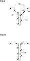
- FIG. 9 illustrates a cross-sectional view taken along the line D-D of FIG. 8 .
- the first middle sipes 41 each include a main portion 41a and a pair of chamfer portions 46 connected to the main portion 41a and having a width greater than that of the main portion 41a.
- an opening width W5 of the chamfer portion 46 is greater than the chamfer width W2 (shown in FIG. 4 ) of the first chamfer portions 18 of one or more first shoulder lateral grooves 16.
- the wear of the first shoulder land portion 11 and the first middle land portion 13 may progress uniform, and uneven wear resistance may be improved.
- a pitch length P3 of the first middle sipes 41 in the tyre circumferential direction is preferably greater than the pitch length P1 of the first shoulder lateral grooves 16 (shown in FIG. 3 ).
- the pitch length P3 is in a range of from 150% to 250% of the pitch length P1. This structure can help to suppress uneven wear of the first middle land portion 13.
- first middle sipes 41 which are located on the first shoulder circumferential groove side, overlap respective projected regions in which axially inner ends of the first shoulder lateral grooves 16 are expanded in parallel with the tyre axial direction onto the first shoulder circumferential groove 6.
- first shoulder lateral grooves 16 tend to open easily when grounding, resulting in improving wet performance.
- the second middle sipes 42 are inclined in the first direction with respect to the tyre axial direction.
- the second middle sipes 42 extend along the first middle sipes 41.
- the angle difference between the second middle sipes 42 and the first middle sipes 41 is equal to or less than 5 degrees.
- a length L8 in the tyre axial direction of the second middle sipes 42 is preferably in a range of from 40% to 60% of a width W6 in the tyre axial direction of the ground contacting surface of the first middle land portion 13.
- FIG. 10 illustrates a cross-sectional view taken along the line E-E of FIG. 8 .
- each second middle sipe 42 for example, includes a pair of sipe walls that connected to the ground contact surface of the first middle land portion 13 directly to form a pair of sharp edges.
- the second middle sipes 42 can provide a large friction force using the edges, helping to improve braking performance.
- the crown land portion 15 is provided with a plurality of the crown lateral grooves 45.
- the crown lateral grooves 45 extend from the second crown circumferential groove 5 and terminate to have closed ends 45a within the crown land portion 15.
- the crown lateral grooves 45 are inclined in the second direction (downward to the right in FIG. 8 ) which is opposite to the first direction with respect to the tyre axial direction.
- An angle of the crown lateral grooves 45 with respect to the tyre axial direction for example, is in a range of from 10 to 30 degrees.
- Such crown lateral grooves 45 can exert frictional force in a direction different from that of the first middle sipes 41, and braking performance can be further improved.
- the crown lateral grooves 45 do not traverse the tyre equator C, and do not traverse the center location in the tyre axial direction of the crown land portion 15.
- a length L9 in the tyre axial direction of the crown lateral grooves 45 is preferably smaller than the length L8 in the tyre axial direction of the second middle sipes 42.
- the length L9 of the crown lateral grooves 45 is in a range of from 35% to 45% of a width W7 in the tyre axial direction of the crown land portion 15.
- the crown lateral grooves 45 can improve wet performance while maintaining uneven wear resistance.
- the second middle land portion 14 is provided with a plurality of third middle sipes 43 and a plurality of the fourth middle sipes 44 which are arranged alternately in the tyre circumferential direction.
- the third middle sipes 43 and the fourth middle sipes 44 traverse the second middle land portion 14 entirely in the tyre axial direction.
- the third middle sipes 43 and the fourth middle sipes 44 are inclined in the first direction with respect to the tyre axial direction.
- An angle of the third middle sipes 43 with respect to the tyre axial direction and an angle of the fourth middle sipes 44 with respect to the tyre axial direction are preferably in a range of 10 to 30 degrees.
- the third middle sipes 43 each, for example, have the same cross-sectional shape as the first middle sipes 41 shown in FIG. 9 . That is, each third middle sipe 43 includes a main portion and a pair of chamfer portions having a greater width than the main portion. The third middle sipes 43 can suppress uneven wear of the second middle land portion 14.
- the fourth middle sipes 44 each, for example, have the same cross-sectional shape as the second middle sipes 42 shown in FIG. 10 . That is, the fourth middle sipes 44 includes a pair of sipe walls that connected to the ground contact surface of the second middle land portion 14 directly to form a pair of sharp edges.
- the fourth middle sipes 44 can provide a large friction force.
- the above-mentioned third middle sipes 43 and the fourth middle sipes 44 which are arranged alternately in the tyre circumferential direction can improve uneven wear resistance and braking performance in a well-balanced manner.
- Tires having a size of 235/50R18 and a tread pattern shown in FIG. 1 were prototyped based on the specifications in Table 1.
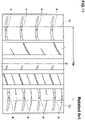
- a tyre having a tread pattern shown in FIG. 11 was also prototyped.
- no chamfer portions are provided on the first shoulder lateral grooves (a) and the second shoulder lateral grooves (b).
- the tyre of comparative example has the substantially same tread pattern shown in FIG. 1 except for the above chamfer structure.
- uneven wear resistance, steering stability and braking performance were tested.
- the common specifications and test methods for each test tyre are as follows.
- the wear state of the first shoulder lateral grooves and the second shoulder lateral grooves was visually checked.
- the test results are indicated in Table 1 using a score with the wear state of the comparative example as 100. The larger the value, the better the uneven wear resistance is.
- the braking performance when driving on dry and wet roads with the above test vehicle was evaluated by the driver's sensuality.
- the test results are indicated in Table 1 using a score with braking performance of the comparative example as 100. The larger the value, the better the braking performance is.
- Table 1 shows the test results. [Table 1] Ref. Ex. 1 Ex. 2 Ex. 3 Ex. 4 Ex. 5 Ex. 6 Ex. 7 Ex. 8 Ex. 9 Figure showing tread pattern FIG. 11 FIG. 1 FIG. 1 FIG. 1 FIG. 1 FIG. 1 FIG. 1 FIG. 1 FIG. 1 FIG. 1 FIG. 1 FIG. 1 FIG. 1 FIG. 1 FIG. 1 FIG. 1 FIG. 1 FIG. 1 FIG. 1 FIG. 1 FIG. 1 FIG. 1 FIG.
- the tyres of the examples have excellent uneven wear resistance and can suppress uneven wear such as H&T wear. It was also confirmed that the tyres of the examples exhibited excellent steering stability. It was also confirmed that the tyres of the examples maintained the braking performance.
Landscapes
- Engineering & Computer Science (AREA)
- Mechanical Engineering (AREA)
- Tires In General (AREA)
Applications Claiming Priority (1)
| Application Number | Priority Date | Filing Date | Title |
|---|---|---|---|
| JP2020191113A JP2022080119A (ja) | 2020-11-17 | 2020-11-17 | タイヤ |
Publications (2)
| Publication Number | Publication Date |
|---|---|
| EP4000961A1 true EP4000961A1 (de) | 2022-05-25 |
| EP4000961B1 EP4000961B1 (de) | 2024-09-25 |
Family
ID=78078156
Family Applications (1)
| Application Number | Title | Priority Date | Filing Date |
|---|---|---|---|
| EP21201033.4A Active EP4000961B1 (de) | 2020-11-17 | 2021-10-05 | Reifen |
Country Status (4)
| Country | Link |
|---|---|
| US (1) | US11897287B2 (de) |
| EP (1) | EP4000961B1 (de) |
| JP (1) | JP2022080119A (de) |
| CN (1) | CN114506186A (de) |
Citations (5)
| Publication number | Priority date | Publication date | Assignee | Title |
|---|---|---|---|---|
| JP2015171840A (ja) * | 2014-03-11 | 2015-10-01 | 住友ゴム工業株式会社 | 空気入りタイヤ |
| EP3064378A1 (de) * | 2015-03-05 | 2016-09-07 | Sumitomo Rubber Industries Limited | Luftreifen |
| EP3135505A1 (de) * | 2015-08-20 | 2017-03-01 | Sumitomo Rubber Industries Limited | Reifen |
| JP2018140745A (ja) | 2017-02-28 | 2018-09-13 | 住友ゴム工業株式会社 | タイヤ |
| US20200338930A1 (en) * | 2017-12-30 | 2020-10-29 | Compagnie Generale Des Etablissments Michelin | Tire with improved snow performance without sacrificing dry braking or wear |
Family Cites Families (9)
| Publication number | Priority date | Publication date | Assignee | Title |
|---|---|---|---|---|
| US6408908B1 (en) * | 1997-09-17 | 2002-06-25 | The Goodyear Tire & Rubber Company | Front tires and rear tires for automobile or light truck |
| JP4665626B2 (ja) * | 2005-06-24 | 2011-04-06 | 横浜ゴム株式会社 | 空気入りタイヤ |
| JP5250016B2 (ja) * | 2010-11-12 | 2013-07-31 | 住友ゴム工業株式会社 | 空気入りタイヤ |
| JP5626383B2 (ja) * | 2012-03-21 | 2014-11-19 | 横浜ゴム株式会社 | 空気入りタイヤ |
| JP6420547B2 (ja) * | 2014-01-27 | 2018-11-07 | 住友ゴム工業株式会社 | 空気入りタイヤ |
| JP6605849B2 (ja) * | 2015-06-12 | 2019-11-13 | 株式会社ブリヂストン | タイヤ |
| WO2017115195A1 (en) * | 2015-12-29 | 2017-07-06 | Pirelli Tyre S.P.A. | A tyre for vehicle wheels |
| JP7012515B2 (ja) * | 2017-11-17 | 2022-01-28 | Toyo Tire株式会社 | 空気入りタイヤ |
| CN111038179B (zh) * | 2018-10-12 | 2023-04-07 | 住友橡胶工业株式会社 | 轮胎 |
-
2020
- 2020-11-17 JP JP2020191113A patent/JP2022080119A/ja active Pending
-
2021
- 2021-10-05 EP EP21201033.4A patent/EP4000961B1/de active Active
- 2021-10-19 CN CN202111215197.7A patent/CN114506186A/zh active Pending
- 2021-10-27 US US17/511,792 patent/US11897287B2/en active Active
Patent Citations (5)
| Publication number | Priority date | Publication date | Assignee | Title |
|---|---|---|---|---|
| JP2015171840A (ja) * | 2014-03-11 | 2015-10-01 | 住友ゴム工業株式会社 | 空気入りタイヤ |
| EP3064378A1 (de) * | 2015-03-05 | 2016-09-07 | Sumitomo Rubber Industries Limited | Luftreifen |
| EP3135505A1 (de) * | 2015-08-20 | 2017-03-01 | Sumitomo Rubber Industries Limited | Reifen |
| JP2018140745A (ja) | 2017-02-28 | 2018-09-13 | 住友ゴム工業株式会社 | タイヤ |
| US20200338930A1 (en) * | 2017-12-30 | 2020-10-29 | Compagnie Generale Des Etablissments Michelin | Tire with improved snow performance without sacrificing dry braking or wear |
Also Published As
| Publication number | Publication date |
|---|---|
| CN114506186A (zh) | 2022-05-17 |
| US20220153064A1 (en) | 2022-05-19 |
| JP2022080119A (ja) | 2022-05-27 |
| US11897287B2 (en) | 2024-02-13 |
| EP4000961B1 (de) | 2024-09-25 |
Similar Documents
| Publication | Publication Date | Title |
|---|---|---|
| EP3178668B1 (de) | Luftreifen | |
| EP3296127B1 (de) | Luftreifen | |
| EP3260308B1 (de) | Reifen | |
| EP3388257B1 (de) | Reifen | |
| EP2578418B1 (de) | Luftreifen | |
| US10836215B2 (en) | Tire | |
| EP2664464B1 (de) | Luftreifen | |
| EP3398793B1 (de) | Reifen | |
| EP3263365B1 (de) | Reifen | |
| US11285762B2 (en) | Tyre | |
| EP3549791B1 (de) | Reifen | |
| EP4173846A1 (de) | Luftreifen | |
| CN110091676B (zh) | 轮胎 | |
| EP3925799B1 (de) | Reifen | |
| US20180236818A1 (en) | Tire | |
| EP4079544B1 (de) | Reifen | |
| EP4091839B1 (de) | Reifen | |
| US11850891B2 (en) | Tire | |
| US12030344B2 (en) | Tire | |
| EP4000961B1 (de) | Reifen | |
| JP2022083207A (ja) | タイヤ | |
| JP2022080118A (ja) | タイヤ | |
| US12054008B2 (en) | Tire | |
| US20220169081A1 (en) | Tire | |
| EP3988336B1 (de) | Reifen |
Legal Events
| Date | Code | Title | Description |
|---|---|---|---|
| PUAI | Public reference made under article 153(3) epc to a published international application that has entered the european phase |
Free format text: ORIGINAL CODE: 0009012 |
|
| STAA | Information on the status of an ep patent application or granted ep patent |
Free format text: STATUS: THE APPLICATION HAS BEEN PUBLISHED |
|
| AK | Designated contracting states |
Kind code of ref document: A1 Designated state(s): AL AT BE BG CH CY CZ DE DK EE ES FI FR GB GR HR HU IE IS IT LI LT LU LV MC MK MT NL NO PL PT RO RS SE SI SK SM TR |
|
| STAA | Information on the status of an ep patent application or granted ep patent |
Free format text: STATUS: REQUEST FOR EXAMINATION WAS MADE |
|
| 17P | Request for examination filed |
Effective date: 20220913 |
|
| RBV | Designated contracting states (corrected) |
Designated state(s): AL AT BE BG CH CY CZ DE DK EE ES FI FR GB GR HR HU IE IS IT LI LT LU LV MC MK MT NL NO PL PT RO RS SE SI SK SM TR |
|
| P01 | Opt-out of the competence of the unified patent court (upc) registered |
Effective date: 20230510 |
|
| STAA | Information on the status of an ep patent application or granted ep patent |
Free format text: STATUS: EXAMINATION IS IN PROGRESS |
|
| 17Q | First examination report despatched |
Effective date: 20230824 |
|
| GRAP | Despatch of communication of intention to grant a patent |
Free format text: ORIGINAL CODE: EPIDOSNIGR1 |
|
| STAA | Information on the status of an ep patent application or granted ep patent |
Free format text: STATUS: GRANT OF PATENT IS INTENDED |
|
| INTG | Intention to grant announced |
Effective date: 20240704 |
|
| GRAS | Grant fee paid |
Free format text: ORIGINAL CODE: EPIDOSNIGR3 |
|
| GRAA | (expected) grant |
Free format text: ORIGINAL CODE: 0009210 |
|
| STAA | Information on the status of an ep patent application or granted ep patent |
Free format text: STATUS: THE PATENT HAS BEEN GRANTED |