EP4000526B1 - Ct-anlage mit einem kollimatorblech und verfahren zum befestigen eines kollimatorblechs einer ct-anlage - Google Patents
Ct-anlage mit einem kollimatorblech und verfahren zum befestigen eines kollimatorblechs einer ct-anlage Download PDFInfo
- Publication number
- EP4000526B1 EP4000526B1 EP21171216.1A EP21171216A EP4000526B1 EP 4000526 B1 EP4000526 B1 EP 4000526B1 EP 21171216 A EP21171216 A EP 21171216A EP 4000526 B1 EP4000526 B1 EP 4000526B1
- Authority
- EP
- European Patent Office
- Prior art keywords
- additional structure
- collimator plate
- ray source
- ray
- collimator
- Prior art date
- Legal status (The legal status is an assumption and is not a legal conclusion. Google has not performed a legal analysis and makes no representation as to the accuracy of the status listed.)
- Active
Links
Images


Classifications
-
- A—HUMAN NECESSITIES
- A61—MEDICAL OR VETERINARY SCIENCE; HYGIENE
- A61B—DIAGNOSIS; SURGERY; IDENTIFICATION
- A61B6/00—Apparatus or devices for radiation diagnosis; Apparatus or devices for radiation diagnosis combined with radiation therapy equipment
- A61B6/06—Diaphragms
-
- A—HUMAN NECESSITIES
- A61—MEDICAL OR VETERINARY SCIENCE; HYGIENE
- A61B—DIAGNOSIS; SURGERY; IDENTIFICATION
- A61B6/00—Apparatus or devices for radiation diagnosis; Apparatus or devices for radiation diagnosis combined with radiation therapy equipment
- A61B6/02—Arrangements for diagnosis sequentially in different planes; Stereoscopic radiation diagnosis
- A61B6/03—Computed tomography [CT]
- A61B6/032—Transmission computed tomography [CT]
- A61B6/035—Mechanical aspects of CT
-
- A—HUMAN NECESSITIES
- A61—MEDICAL OR VETERINARY SCIENCE; HYGIENE
- A61B—DIAGNOSIS; SURGERY; IDENTIFICATION
- A61B6/00—Apparatus or devices for radiation diagnosis; Apparatus or devices for radiation diagnosis combined with radiation therapy equipment
- A61B6/02—Arrangements for diagnosis sequentially in different planes; Stereoscopic radiation diagnosis
- A61B6/03—Computed tomography [CT]
-
- A—HUMAN NECESSITIES
- A61—MEDICAL OR VETERINARY SCIENCE; HYGIENE
- A61B—DIAGNOSIS; SURGERY; IDENTIFICATION
- A61B6/00—Apparatus or devices for radiation diagnosis; Apparatus or devices for radiation diagnosis combined with radiation therapy equipment
- A61B6/40—Arrangements for generating radiation specially adapted for radiation diagnosis
-
- A—HUMAN NECESSITIES
- A61—MEDICAL OR VETERINARY SCIENCE; HYGIENE
- A61B—DIAGNOSIS; SURGERY; IDENTIFICATION
- A61B6/00—Apparatus or devices for radiation diagnosis; Apparatus or devices for radiation diagnosis combined with radiation therapy equipment
- A61B6/42—Arrangements for detecting radiation specially adapted for radiation diagnosis
- A61B6/4208—Arrangements for detecting radiation specially adapted for radiation diagnosis characterised by using a particular type of detector
-
- A—HUMAN NECESSITIES
- A61—MEDICAL OR VETERINARY SCIENCE; HYGIENE
- A61B—DIAGNOSIS; SURGERY; IDENTIFICATION
- A61B6/00—Apparatus or devices for radiation diagnosis; Apparatus or devices for radiation diagnosis combined with radiation therapy equipment
- A61B6/44—Constructional features of apparatus for radiation diagnosis
- A61B6/4405—Constructional features of apparatus for radiation diagnosis the apparatus being movable or portable, e.g. handheld or mounted on a trolley
-
- A—HUMAN NECESSITIES
- A61—MEDICAL OR VETERINARY SCIENCE; HYGIENE
- A61B—DIAGNOSIS; SURGERY; IDENTIFICATION
- A61B6/00—Apparatus or devices for radiation diagnosis; Apparatus or devices for radiation diagnosis combined with radiation therapy equipment
- A61B6/44—Constructional features of apparatus for radiation diagnosis
- A61B6/4411—Constructional features of apparatus for radiation diagnosis the apparatus being modular
-
- A—HUMAN NECESSITIES
- A61—MEDICAL OR VETERINARY SCIENCE; HYGIENE
- A61B—DIAGNOSIS; SURGERY; IDENTIFICATION
- A61B6/00—Apparatus or devices for radiation diagnosis; Apparatus or devices for radiation diagnosis combined with radiation therapy equipment
- A61B6/44—Constructional features of apparatus for radiation diagnosis
- A61B6/4429—Constructional features of apparatus for radiation diagnosis related to the mounting of source units and detector units
- A61B6/4435—Constructional features of apparatus for radiation diagnosis related to the mounting of source units and detector units the source unit and the detector unit being coupled by a rigid structure
Definitions
- the invention relates to a CT system, i.e. a computer tomography system, and a method for fastening a collimator plate of a CT system.
- Such CT systems are generally known.
- the arrangement of the X-ray source, X-ray detector and collimator plate is generic.
- the axis of rotation and the examination area are the same for all such groups.
- a CT system consists of many different components. The components themselves often consist of several individual parts. Such components are first assembled separately and then tested. Only after testing are these components integrated into the CT system as a whole installed. After installation in the CT system, the CT system as a whole is tested again.
- US4361902 A discloses a CT system according to the preamble of claim 1.
- the collimator unit comprises a base body to which the collimator plate is attached.
- An X-ray sensor can also be attached to the base body for dose detection.
- the collimator unit is detachably attached to the additional structure with its base body.
- the procedure of the prior art is ultimately very cost-intensive and consumes unnecessary resources.
- the object of the present invention is to create possibilities by means of which a more efficient construction and, associated with this, more efficient maintenance and repair of a CT system are possible.
- the holding structure can be designed in particular for the detachable reception of the X-ray sensor, for example for the positively detachable reception of the X-ray sensor.
- the X-ray sensor can be detachably received in the holding structure in particular between the X-ray source and the examination area, for example positively received, and attached to the holding structure in such a way that the X-ray sensor as such can be detachable from the holding structure, in particular as such can be detachable from the holding structure independently of the collimator plate.
- the collimator plate and a diameter of the examination area are matched to the same body part of the patient.
- a position of the collimator plate and/or a passage opening of the collimator plate for X-rays emitted by the X-ray source can be matched to the body part of the patient.
- the diameter of the examination area can in particular relate to an extension of the examination area perpendicular to the axis of rotation.
- a dimension of the passage opening of the collimator plate that is parallel to the axis of rotation and the diameter of the examination area can be matched to the same body part of the patient.
- the dimension of the passage opening of the collimator plate that is parallel to the axis of rotation can in particular determine a layer collimation of a fan beam of the X-rays emitted by the X-ray source.
- a dimension of the passage opening of the collimator plate that is perpendicular to the axis of rotation and the diameter of the examination area are matched to the same body part of the patient.
- the collimator plate extends flatly in a collimator plate surface.
- the collimator plate surface can be flat or curved, for example.
- the collimator plate surface can in particular lie in a collimator plate plane and/or be parallel to the axis of rotation.
- the dimension of the passage opening of the collimator plate parallel to the axis of rotation relates to an extension of the passage opening of the collimator plate parallel to the axis of rotation and parallel to the collimator plate surface and/or that the dimension of the passage opening of the collimator plate perpendicular to the axis of rotation relates to an extension of the passage opening perpendicular to the axis of rotation and parallel to the collimator plate surface.
- the body part of the patient can in particular be his head.
- the diameter of the examination area can be less than 45 cm, for example less than 40 cm, and/or greater than 25 cm, for example greater than 30 cm.
- the examination area can in particular be designed in the form of a tunnel-shaped opening.
- one or the other aperture can be positioned in the beam path as required.
- the additional structure possibly with the exception of the mobility of the collimator plate as a whole - has no movable elements. Rather, the additional structure can only be rotated as a whole relative to the base structure about the axis of rotation. This significantly reduces the probability of defects of any kind occurring in the additional structure.
- the probability of a defect in the additional structure occurring can be significantly smaller than the probability of a defect in the X-ray sensor occurring and/or significantly smaller than the probability of a defect in the collimator drive occurring.
- the movable element can in particular be a filter by means of which the X-ray radiation emitted by the X-ray source is filtered.
- the collimator plate can be detached from the additional structure, while the element drive is attached to the additional structure and the movable element is mounted on the additional structure. It is therefore not necessary to first detach the element drive from the additional structure and/or remove the movable element from the additional structure and only then remove the collimator plate. Instead, the collimator plate can be removed directly and replaced with another collimator plate if necessary.
- the X-ray sensor can be detached from the additional structure, while the element drive is attached to the additional structure and the movable element is mounted on the additional structure. It is therefore not necessary to first detach the element drive from the additional structure and/or remove the movable element from the additional structure and only then remove the X-ray sensor. Instead, the X-ray sensor can be removed directly and, if necessary, replaced by another X-ray sensor.
- the CT system is designed as a mobile CT system.
- the base structure has wheels in a floor area, by means of which the CT system stands on a surface and is mounted so that it can move relative to the surface.
- a CT system 1 comprises a basic structure 1a and an additional structure 1b.
- the additional structure 1b is rotatably mounted on the base structure 1a, so that the additional structure 1b is rotatable relative to the base structure 1a about a rotation axis 3.
- the additional structure 1b is often referred to as a disk or drum.
- the additional structure 1b can in particular be designed in one piece, for example as a single part that cannot be further disassembled without destroying it.
- the additional structure 1b can be designed as a cast part.
- the CT system 1 can be arranged in a fixed location.
- the CT system 1 can be mobile.
- the base structure 1a has wheels 4 in a floor area, by means of which the CT system 1 stands on a base 5 and is mounted so as to be movable relative to the base 5.
- the CT system 1 further comprises an X-ray source 6 and an X-ray detector 7.
- the X-ray source 6 can be designed as a conventional X-ray source.
- the X-ray detector 7 is used for imaging. It is often designed as a line detector or as an area detector.
- the X-ray source 6 and the X-ray detector 7 are attached to the additional structure 1b. In the attached state, the X-ray source 6 and the X-ray detector 7 are arranged in a fixed position relative to one another. The X-ray source 6 and the X-ray detector 7 are thus in this case together with the additional structure 1b around the axis of rotation 3 rotatable. However, they remain stationary relative to each other.
- an examination area 8 in the form of a tunnel-shaped opening.
- a patient 9 or a body part of a patient 9 for example his head
- the additional structure 1b has a holding structure 10, wherein the holding structure 10 is designed to detachably receive the collimator plate 15.
- the collimator plate 15 is detachably received in the holding structure 10 between the X-ray source 6 and the examination area 8 and is fastened to the holding structure 10 such that the collimator plate 15 as such can be detached from the holding structure 1b.
- the additional structure 1b further comprises an annular rotating frame 11 which extends flatly in a rotation plane 3E.
- the rotation plane 3E is perpendicular to the rotation axis 3.
- the holding structure 10 protrudes substantially perpendicular to the rotation plane 3E relative to the annular rotating frame 11.
- the CT system further comprises a collimator plate 15.
- the collimator plate 15 is attached to the additional structure 1b between the X-ray source 6 and the examination area 8.
- the additional structure 1b can have a holding structure 10 to which the X-ray source 6 is attached.
- the holding structure 10 is in this case part of the additional structure 1b, for example a non-detachable part of the cast part.
- the collimator plate 15 can for example - see additional FIG 3 - be fastened on the underside of the holding structure 10, i.e. on the side of the holding structure 10 facing away from the X-ray source 6, so that the holding structure 10 is arranged between the X-ray source 6 and the collimator plate 15.
- the collimator plate 15 can be detached from the additional structure 1b, and indeed as such. In order to detach the collimator plate 15 from the additional structure 1b, it is not a base body that is designed to receive the collimator plate 15 that is detached from the additional structure 1b, but the collimator plate 15 itself. It may be necessary to at least partially remove a panel of the CT system before detaching the collimator plate 15. Nevertheless, the detachment of the collimator plate 15 as such takes place without detaching a base body that is designed to receive the collimator plate 15 from the additional structure 1b.
- the collimator plate 15 can be attached to the additional structure 1b, for example, by means of fastening screws 16.
- the collimator plate 15 can be positioned, for example, as shown in FIG 3 recesses which interact with centering pins 18 (or similar positioning aids) of the additional structure 1b.
- the additional structure 1b generally also has an X-ray sensor 13.
- the X-ray sensor 13 is not used for imaging. Rather, it is used for dose measurement.
- the X-ray sensor 13 is detachably attached to the additional structure 1b, for example by means of fastening screws 14.
- the X-ray sensor 13 is also attached in such a way that it is located between the X-ray source 6 and the examination area 8.
- the X-ray sensor 13 can be detached from the additional structure 1b as such, analogous to the collimator plate 15.
- the X-ray sensor 13 can also be attached to the underside of the holding structure 10, for example by means of fastening screws 14. In this case, to detach the X-ray sensor 13 from the additional structure 1b, only the fastening screws 14 have to be loosened.
- the collimator plate 15 when it is attached to the additional structure 1b, is arranged in a fixed position relative to the X-ray source 6.
- the collimator plate 15 has only a single passage opening 15a for X-rays emitted by the X-ray source 6.
- the passage opening 15a is generally in the shape of a rectangle, usually even in the shape of a fairly narrow rectangle, i.e. a slot.
- the collimator plate 15 it is possible for the collimator plate 15 to be movably mounted on the additional structure 1b.
- the collimator plate 15 can be attached to a carriage 19 (or a similar element), the carriage 19 being guided in a guide 20 so that it can be moved linearly.
- the direction in which the carriage 19 can be moved is shown in FIG 4 indicated by an arrow 21.
- the movement of the collimator plate 15 is carried out by a collimator drive 22.
- This is in FIG 4 indicated by a dashed line from the collimator drive 22 to the guide 20.
- the collimator drive 22 is detachably attached to the additional structure 1b, for example by means of fastening screws 23.
- the collimator drive 22 can be used to move the collimator plate 15 into several defined positions.
- the collimator plate 15 also has several through-openings 15a. Depending on the positioning of the collimator plate 15, the X-ray radiation from the X-ray source 6 passes through one or the other of the through-openings 15a.
- the collimator plate 15, in particular the dimension w of the passage opening 15a of the collimator plate 15 parallel to the rotation axis 3, and the diameter d of the examination region 8 perpendicular to the rotation axis 3 are adapted to the same body part of the patient 9, wherein the body part of the patient 9 is the head of the patient 9.
- An element 25 that can be moved by means of an element drive 24 is also attached to the additional structure 1b, in particular to the holding structure 10, which is a component of the additional structure 1b.
- the movable element 25 can, for example, be mounted in a carriage 27 in a similar way to the collimator plate 15, which in turn is guided in a guide 28.
- the movable element 25 is attached between the X-ray source 6 and the examination area 8. It can, for example, be designed as a filter for filtering the X-ray radiation.
- the movable element 25 can be moved by means of the element drive 24, for example in the direction of an arrow 26.
- the arrow 26 is generally parallel to the arrow 21.
- the element drive 24 is also attached to the additional structure 1b.
- the element drive 24 is preferably detachably attached to the additional structure 1b. For example, it can be attached using fastening screws 29.
- the movable element 25 can be detachable from the additional structure 1b, for example by loosening fastening screws 30.
- the element drive 24 and the movable element 25 are preferably arranged in such a way that they do not hinder the detachment of the X-ray sensor 13 and/or the collimator plate 15 from the additional structure 1b.
- the X-ray sensor 13 and/or the collimator plate 15 are therefore preferably also detachable from the additional structure 1b, while the element drive 24 and/or the movable element 25 are attached to the additional structure 1b.
- this can be achieved by firstly attaching the holding structure 10, then the movable element 25 and only then the collimator plate 15, as viewed from the X-ray source 6 to the X-ray detector 7.
- the CT system comprises a base structure 1a, an additional structure 1b, an X-ray source 6, an X-ray detector 7 and a collimator plate 15.
- the additional structure 1b is rotatably mounted on the base structure 1a so that the additional structure 1b can rotate relative to the base structure 1a about a rotation axis 3.
- the X-ray source 6 and the X-ray detector 7 are attached to the additional structure 1b such that they are arranged in a fixed position relative to one another and an examination area 8 is located between the X-ray source 6 and the X-ray detector 7 in the area of the rotation axis 3, in which a patient 9 or a body part of a patient 9 can be arranged.
- the collimator plate 15 is detachably attached to the additional structure 1b between the X-ray source 6 and the examination area 8. As such, it can be detached from the additional structure 1b.
- the present invention has the particular advantage that a direct, immediate removal is possible, in particular of the collimator plate 15 and possibly also of other components such as the X-ray sensor 13. This is particularly advantageous if the various components can be replaced independently of one another, i.e. if - with the exception of the cover - a certain component can be replaced without first having to loosen other components and then reattach them.
Landscapes
- Health & Medical Sciences (AREA)
- Life Sciences & Earth Sciences (AREA)
- Engineering & Computer Science (AREA)
- Medical Informatics (AREA)
- Optics & Photonics (AREA)
- Biomedical Technology (AREA)
- Biophysics (AREA)
- High Energy & Nuclear Physics (AREA)
- Veterinary Medicine (AREA)
- Nuclear Medicine, Radiotherapy & Molecular Imaging (AREA)
- Public Health (AREA)
- Pathology (AREA)
- Radiology & Medical Imaging (AREA)
- Physics & Mathematics (AREA)
- Heart & Thoracic Surgery (AREA)
- Molecular Biology (AREA)
- Surgery (AREA)
- Animal Behavior & Ethology (AREA)
- General Health & Medical Sciences (AREA)
- Pulmonology (AREA)
- Theoretical Computer Science (AREA)
- Apparatus For Radiation Diagnosis (AREA)
Description
- Die Erfindung betrifft eine CT-Anlage, also eine Computertomographie-Anlage, und ein Verfahren zum Befestigen eines Kollimatorblechs einer CT-Anlage.
- Die vorliegende Erfindung geht aus von einer CT-Anlage,
- wobei die CT-Anlage eine Basisstruktur, eine Zusatzstruktur, eine Röntgenquelle, einen Röntgendetektor und ein Kollimatorblech umfasst,
- wobei die Zusatzstruktur an der Basisstruktur drehbar gelagert ist, so dass die Zusatzstruktur relativ zu der Basisstruktur um eine Rotationsachse rotierbar ist,
- wobei die Röntgenquelle und der Röntgendetektor an der Zusatzstruktur derart befestigt sind, dass sie relativ zueinander ortsfest angeordnet sind und sich zwischen der Röntgenquelle und dem Röntgendetektor im Bereich der Rotationsachse ein Untersuchungsbereich befindet, in dem ein Patient oder ein Körperteil eines Patienten angeordnet werden kann.
- Derartige CT-Anlagen sind allgemein bekannt. Die Anordnung von Röntgenquelle, Röntgendetektor und Kollimatorblech ist generisch. Insbesondere können auch mehrere, beispielsweise zwei, derartige Gruppen vorhanden sein, die jeweils eine eigene Röntgenquelle, einen eigenen Röntgendetektor und ein eigenes Kollimatorblech umfassen. Die Rotationsachse und der Untersuchungsbereich sind jedoch für alle derartigen Gruppen dieselben.
- Eine CT-Anlage besteht aus vielen verschiedenen Komponenten. Die Komponenten bestehen oftmals ihrerseits ebenfalls aus mehreren Einzelteilen. Derartige Komponenten werden zunächst für sich zusammengebaut und sodann getestet. Erst nach dem Testen werden diese Komponenten in die CT-Anlage als Ganzes eingebaut. Nach dem Einbauen in die CT-Anlage erfolgt ein erneuter Test der CT-Anlage als Ganzes.
- Bei der Vorgehensweise des Standes der Technik ergeben sich ein hoher Montageaufwand und hiermit verbunden hohe Kosten.
-
US4361902 A offenbart eine CT Anlage gemäß Oberbegriff von Anspruch 1. - Fällt bei einer Komponente, die ihrerseits aus mehreren Einzelteilen besteht, eines der Einzelteile der Komponente aus, so kann es erforderlich sein, dass die gesamte Komponente ausgebaut wird, wobei es erst nach dem Ausbau der Komponente mit dem defekten Einzelteil möglich ist, das defekte Einzelteil auszutauschen.
- Dies gilt insbesondere auch für eine im Stand der Technik vorhandene Kollimatoreinheit. Die Kollimatoreinheit umfasst einen Grundkörper, an dem das Kollimatorblech befestigt ist. An dem Grundkörper kann ferner zur Dosiserfassung ein Röntgensensor befestigt sein. Mit ihrem Grundkörper ist die Kollimatoreinheit lösbar an der Zusatzstruktur befestigt.
- Die Vorgehensweise des Standes der Technik ist im Ergebnis sehr kostenintensiv und verbraucht unnötig viele Ressourcen. Die Aufgabe der vorliegenden Erfindung besteht darin, Möglichkeiten zu schaffen, mittels derer ein effizienterer Aufbau und hiermit verbunden eine effizientere Wartung und Reparatur einer CT-Anlage möglich sind.
- Die Aufgabe wird jeweils gelöst durch eine CT-Anlage mit den Merkmalen des Anspruchs 1 und durch ein Verfahren mit den Merkmalen des Anspruchs 11. Vorteilhafte Ausgestaltungen der erfindungsgemäßen CT-Anlage sind Gegenstand der abhängigen Ansprüche.
- Die Haltestruktur kann insbesondere zur lösbaren Aufnahme des Röntgensensors, beispielsweise zur formschlüssigen lösbaren Aufnahme des Röntgensensors, eingerichtet sein. Der Röntgensensor kann insbesondere zwischen der Röntgenquelle und dem Untersuchungsbereich derart lösbar in die Haltestruktur aufgenommen, beispielsweise formschlüssig aufgenommen, und an der Haltestruktur befestigt sein, dass der Röntgensensor als solcher von der Haltestruktur lösbar ist, insbesondere als solcher unabhängig von dem Kollimatorblech von der Haltestruktur lösbar ist.
- Eine Ausführungsform sieht vor, dass das Kollimatorblech und ein Durchmesser des Untersuchungsbereichs auf dasselbe Körperteil des Patienten abgestimmt sind. Insbesondere kann hierfür eine Lage des Kollimatorblechs und/oder eine Durchtrittsöffnung des Kollimatorblechs für von der Röntgenquelle emittierte Röntgenstrahlung auf das Körperteil des Patientenabgestimmt sein. Der Durchmesser des Untersuchungsbereichs kann insbesondere eine zu der Rotationsachse senkrechte Erstreckung des Untersuchungsbereichs betreffen.
- Insbesondere können eine zu der Rotationsachse parallele Abmessung der Durchtrittsöffnung des Kollimatorblechs und der Durchmesser des Untersuchungsbereichs auf dasselbe Körperteil des Patienten abgestimmt sein. Durch die zu der Rotationsachse parallele Abmessung der Durchtrittsöffnung des Kollimatorblechs kann insbesondere eine Schichtkollimation eines Fächerstrahls der von der Röntgenquelle emittierten Röntgenstrahlung bestimmt sein. Weiterhin kann vorgesehen sein, dass eine zu der Rotationsachse senkrechte Abmessung der Durchtrittsöffnung des Kollimatorblechs und der Durchmesser des Untersuchungsbereichs auf dasselbe Körperteil des Patienten abgestimmt sind.
- Insbesondere kann vorgesehen sein, dass sich das Kollimatorblech flächig in einer Kollimatorblechfläche erstreckt. Die Kollimatorblechfläche kann beispielsweise flach oder gekrümmt sein. Die Kollimatorblechfläche kann insbesondere in einer Kollimatorblechebene liegen und/oder parallel zu der Rotationsachse sein.
- Weiterhin kann vorgesehen sein, dass die zu der Rotationsachse parallele Abmessung der Durchtrittsöffnung des Kollimatorblechs eine zu der Rotationsachse parallele und zu der Kollimatorblechfläche parallele Erstreckung der Durchtrittsöffnung des Kollimatorblechs betrifft und/oder dass die zu der Rotationsachse senkrechte Abmessung der Durchtrittsöffnung des Kollimatorblechs eine zu der Rotationsachse senkrechte und zu der Kollimatorblechfläche parallele Erstreckung der Durchtrittsöffnung betrifft.
- Durch die Abstimmung des Kollimatorblechs und des Durchmessers des Untersuchungsbereichs aufeinander ist - bezogen auf das Körperteil des Patienten - ein optimierter Betrieb der CT-Anlage möglich. Insbesondere kann der Bedarf an unterschiedlichen Durchtrittsöffnungen, die sich in Bezug auf die jeweilige zu der Rotationsachse parallele Abmessung der Durchtrittsöffnung unterscheiden, verringert sein, wenn aufgrund des Durchmessers des Untersuchungsbereichs die Verwendung der CT-Anlage für bestimmte Körperbereiche des Patienten ausgeschlossen werden kann.
- Das Körperteil des Patienten kann insbesondere dessen Kopf sein. Insbesondere zu diesem Zweck - aber nicht notwendigerweise ausschließlich zu diesem Zweck - kann der Durchmesser des Untersuchungsbereichs kleiner als 45 cm, beispielsweise kleiner als 40 cm, und/oder größer als 25 cm, beispielsweise größer als 30 cm, sein. Der Untersuchungsbereich kann insbesondere in Form einer tunnelförmigen Öffnung ausgebildet sein.
- Weiterhin kann vorgesehen sein, dass das Kollimatorblech im an der Zusatzstruktur befestigten Zustand relativ zur Röntgenquelle ortsfest angeordnet ist. Alternativ ist es möglich,
- dass das Kollimatorblech mehrere Durchtrittsöffnungen für von der Röntgenquelle emittierte Röntgenstrahlung aufweist,
- dass das Kollimatorblech an der Zusatzstruktur beweglich gelagert ist und
- dass die CT-Anlage einen an der Zusatzstruktur lösbar befestigten Kollimatorantrieb aufweist, mittels dessen das Kollimatorblech bewegbar ist.
- In diesem Fall kann durch entsprechende Positionierung des Kollimatorblechs je nach Bedarf die eine oder die andere Durchtrittsöffnung im Strahlengang positioniert werden.
- Eine Ausführungsform sieht vor, dass die Zusatzstruktur - gegebenenfalls mit Ausnahme der Bewegbarkeit des Kollimatorblechs als Ganzes - keine bewegbaren Elemente aufweist. Vielmehr ist die Zusatzstruktur nur als Ganzes relativ zu der Basisstruktur um die Rotationsachse rotierbar. Dadurch wird die Wahrscheinlichkeit, dass an der Zusatzstruktur Defekte irgendwelcher Art auftreten, deutlich reduziert. Insbesondere kann die Wahrscheinlichkeit, dass ein Defekt der Zusatzstruktur auftritt, deutlich kleiner sein als die Wahrscheinlichkeit, dass ein Defekt des Röntgensensors auftritt, und/oder deutlich kleiner sein als die Wahrscheinlichkeit, dass ein Defekt des Kollimatorantriebs auftritt.
- Alternativ ist es möglich,
- dass die CT-Anlage (mindestens) einen Elementantrieb und ein mittels des Elementantriebs bewegbares Element aufweist,
- dass das bewegbare Element zwischen der Röntgenquelle und dem Untersuchungsbereich an der Zusatzstruktur befestigt ist und
- dass der Elementantrieb und das bewegbare Element von der Zusatzstruktur lösbar sind.
- Dadurch ergibt sich eine erhöhte Flexibilität beim Betrieb der CT-Anlage, wobei dennoch auch der Elementantrieb und/oder das bewegbare Element bei Bedarf ausgetauscht werden können. Das bewegbare Element kann insbesondere ein Filter sein, mittels dessen die von der Röntgenquelle emittierte Röntgenstrahlung gefiltert wird.
- Vorzugsweise ist auch im Falle eines Elementantriebs und eines bewegbaren Elements das Kollimatorblech von der Zusatzstruktur lösbar, während der Elementantrieb an der Zusatzstruktur befestigt ist und das bewegbare Element an der Zusatzstruktur gelagert ist. Es ist also nicht erforderlich, zunächst den Elementantrieb von der Zusatzstruktur zu lösen und/oder das bewegbare Element von der Zusatzstruktur zu entfernen und erst dann das Kollimatorblech zu entfernen. Vielmehr kann direkt das Kollimatorblech entfernt und gegebenenfalls durch ein anderes Kollimatorblech ersetzt werden.
- Vorzugsweise ist auch im Falle eines Elementantriebs und eines bewegbaren Elements der Röntgensensor von der Zusatzstruktur lösbar, während der Elementantrieb an der Zusatzstruktur befestigt ist und das bewegbare Element an der Zusatzstruktur gelagert ist. Es ist also nicht erforderlich, zunächst den Elementantrieb von der Zusatzstruktur zu lösen und/oder das bewegbare Element von der Zusatzstruktur zu entfernen und erst dann den Röntgensensor zu entfernen. Vielmehr kann direkt der Röntgensensor entfernt und gegebenenfalls durch einen anderen Röntgensensor ersetzt werden.
- In einer besonders bevorzugten Ausgestaltung ist die CT-Anlage als mobile CT-Anlage ausgebildet. In diesem Fall weist die Basisstruktur in einem Bodenbereich Räder auf, mittels derer die CT-Anlage auf einem Untergrund aufsteht und relativ zu dem Untergrund bewegbar gelagert ist.
- Die Erfindung betrifft ferner ein Verfahren zum Befestigen eines Kollimatorblechs einer CT-Anlage,
- wobei die CT-Anlage eine Basisstruktur, eine Zusatzstruktur, eine Röntgenquelle, einen Röntgendetektor und das Kollimatorblech umfasst,
- wobei die Zusatzstruktur an der Basisstruktur drehbar gelagert ist, so dass die Zusatzstruktur relativ zu der Basisstruktur um eine Rotationsachse rotierbar ist,
- wobei die Röntgenquelle und der Röntgendetektor an der Zusatzstruktur derart befestigt sind, dass sie relativ zueinander ortsfest angeordnet sind und sich zwischen der Röntgenquelle und dem Röntgendetektor im Bereich der Rotationsachse ein Untersuchungsbereich befindet, in dem ein Patient oder ein Körperteil eines Patienten angeordnet werden kann,
- Im Rahmen der Erfindung können Merkmale, welche in Bezug auf unterschiedliche Ausführungsformen der Erfindung und/oder unterschiedliche Anspruchskategorien (Verfahren, Verwendung, Vorrichtung, System, Anordnung usw.) beschrieben sind, zu weiteren Ausführungsformen der Erfindung kombiniert werden. Beispielsweise kann ein Anspruch, der ein Verfahren betrifft, auch mit Merkmalen, die im Zusammenhang mit einer Vorrichtung beschrieben oder beansprucht sind, weitergebildet werden und umgekehrt. Funktionale Merkmale eines Verfahrens können dabei durch entsprechend ausgebildete gegenständliche Komponenten ausgeführt werden. Neben den in dieser Anmeldung ausdrücklich beschriebenen Ausführungsformen der Erfindung sind vielfältige weitere Ausführungsformen der Erfindung denkbar, zu denen der Fachmann gelangen kann, ohne den Bereich der Erfindung zu verlassen, der durch die Ansprüche vorgegeben ist.
- Im Folgenden wird die Erfindung anhand von Ausführungsbeispielen unter Hinweis auf die beigefügten Figuren erläutert. Die Darstellung in den Figuren ist schematisch, stark vereinfacht und nicht zwingend maßstabsgetreu.
- FIG 1
- schematisch eine CT-Anlage von vorne,
- FIG 2
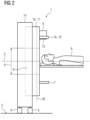
- die CT-Anlage von
FIG 1 von der Seite, - FIG 3
- eine Haltestruktur von unten,
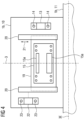
- FIG 4
- eine weitere Haltestruktur von unten und
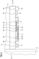
- FIG 5
- eine weitere Haltestruktur von der Seite.
- Gemäß den
FIG 1 und2 umfasst eine CT-Anlage 1 eine Basisstruktur 1a und eine Zusatzstruktur 1b. Wie inFIG 1 durch einen Pfeil 2 angedeutet ist, ist die Zusatzstruktur 1b an der Basisstruktur 1a drehbar gelagert, so dass die Zusatzstruktur 1b relativ zu der Basisstruktur 1a um eine Rotationsachse 3 rotierbar ist. Die Zusatzstruktur 1b wird oftmals als Disk oder Drum bezeichnet. Die Zusatzstruktur 1b kann insbesondere einstückig ausgebildet sein, beispielsweise als einziges Teil, das nicht weiter zerlegt werden kann, ohne es zu zerstören. Beispielsweise kann die Zusatzstruktur 1b als Gussteil ausgebildet sein. - Die CT-Anlage 1 kann ortsfest angeordnet sein. Alternativ kann die CT-Anlage 1 mobil sein. Im letztgenannten Fall weist die Basisstruktur 1a in einem Bodenbereich Räder 4 auf, mittels derer die CT-Anlage 1 auf einem Untergrund 5 aufsteht und relativ zu dem Untergrund 5 bewegbar gelagert ist.
- Die CT-Anlage 1 umfasst ferner eine Röntgenquelle 6 und einen Röntgendetektor 7. Die Röntgenquelle 6 kann als übliche Röntgenquelle ausgebildet sein. Der Röntgendetektor 7 dient der Bildgebung. Er ist oftmals als Zeilendetektor oder als Flächendetektor ausgebildet. Die Röntgenquelle 6 und der Röntgendetektor 7 sind an der Zusatzstruktur 1b befestigt. Im befestigten Zustand sind die Röntgenquelle 6 und der Röntgendetektor 7 relativ zueinander ortsfest angeordnet. Die Röntgenquelle 6 und der Röntgendetektor 7 sind somit in diesem Fall zusammen mit der Zusatzstruktur 1b um die Rotationsachse 3 drehbar. Relativ zueinander bleiben sie aber dennoch ortsfest.
- Zwischen der Röntgenquelle 6 und dem Röntgendetektor 7 befindet sich im Bereich der Rotationsachse 3 ein Untersuchungsbereich 8 in Form einer tunnelförmigen Öffnung. Im Untersuchungsbereich 8 kann - siehe
FIG 2 - ein Patient 9 oder ein Körperteil eines Patienten 9 (beispielsweise dessen Kopf) angeordnet werden. - Die Zusatzstruktur 1b weist eine Haltestruktur 10 auf, wobei die Haltestruktur 10 zur lösbaren Aufnahme des Kollimatorblechs 15 eingerichtet ist. Das Kollimatorblech 15 ist zwischen der Röntgenquelle 6 und dem Untersuchungsbereich 8 derart lösbar in die Haltestruktur 10 aufgenommen und an der Haltestruktur 10 befestigt, dass das Kollimatorblech 15 als solches von der Haltestruktur 1b lösbar ist.
- Die Zusatzstruktur 1b weist ferner einen ringförmigen Drehrahmen 11 auf, der sich flächig in einer Rotationsebene 3E erstreckt. Die Rotationsebene 3E ist senkrecht zu der Rotationsachse 3. Die Haltestruktur 10 ragt im Wesentlichen senkrecht zu der Rotationsebene 3E relativ zu dem ringförmigen Drehrahmen 11 heraus.
- Die CT-Anlage umfasst ferner ein Kollimatorblech 15. Das Kollimatorblech 15 ist zwischen der Röntgenquelle 6 und dem Untersuchungsbereich 8 an der Zusatzstruktur 1b befestigt. Beispielsweise kann die Zusatzstruktur 1b eine Haltestruktur 10 aufweisen, an welcher die Röntgenquelle 6 befestigt ist. Die Haltestruktur 10 ist in diesem Fall Bestandteil der Zusatzstruktur 1b, beispielsweise ein unlösbarer Bestandteil des Gussteils. Im Falle der Haltestruktur 10 kann das Kollimatorblech 15 beispielsweise - siehe ergänzend
FIG 3 - auf der Unterseite der Haltestruktur 10 befestigt sein, also auf der von der Röntgenquelle 6 abgewandten Seite der Haltestruktur 10, so dass die Haltestruktur 10 zwischen der Röntgenquelle 6 und dem Kollimatorblech 15 angeordnet ist. - Das Kollimatorblech 15 ist von der Zusatzstruktur 1b lösbar, und zwar als solches. Zum Lösen des Kollimatorblechs 15 von der Zusatzstruktur 1b wird also nicht ein Grundkörper, der zur Aufnahme des Kollimatorblechs 15 eingerichtet ist, von der Zusatzstruktur 1b gelöst, sondern das Kollimatorblech 15 selbst. Es kann zwar erforderlich sein, vor dem Lösen des Kollimatorblechs 15 eine Verkleidung der CT-Anlage zumindest teilweise zu entfernen. Dennoch erfolgt das Lösen des Kollimatorblechs 15 als solches, ohne dass ein Lösen eines Grundkörpers, der zur Aufnahme des Kollimatorblechs 15 eingerichtet ist, von der Zusatzstruktur 1b erfolgt.
- Das Kollimatorblech 15 kann beispielsweise mittels Befestigungsschrauben 16 an der Zusatzstruktur 1b befestigt sein. Für eine exakte Positionierung des Kollimatorblechs 15 relativ zur Zusatzstruktur 1b (und damit auch relativ zur Röntgenquelle 6) kann das Kollimatorblech 15 beispielsweise entsprechend der Darstellung in
FIG 3 Ausnehmungen aufweisen, die mit Zentrierzapfen 18 (oder ähnlichen Positionierhilfen) der Zusatzstruktur 1b zusammenwirken. - Die Zusatzstruktur 1b weist in aller Regel ferner einen Röntgensensor 13 auf. Der Röntgensensor 13 dient - im Gegensatz zum Röntgendetektor 7 - nicht der Bildgebung. Er dient vielmehr der Dosismessung. Der Röntgensensor 13 ist - beispielsweise mittels Befestigungsschrauben 14 - lösbar an der Zusatzstruktur 1b befestigt. Der Röntgensensor 13 ist ebenfalls derart befestigt, dass er sich zwischen der Röntgenquelle 6 und dem Untersuchungsbereich 8 befindet. Weiterhin ist der Röntgensensor 13 - analog zum Kollimatorblech 15 - als solcher von der Zusatzstruktur 1b lösbar. Der Röntgensensor 13 kann beispielsweise mittels Befestigungsschrauben 14 ebenfalls auf der Unterseite der Haltestruktur 10 befestigt sein. In diesem Fall müssen zum Lösen des Röntgensensors 13 von der Zusatzstruktur 1b lediglich die Befestigungsschrauben 14 gelöst werden.
- Es ist, wie in
FIG 3 dargestellt, möglich, dass das Kollimatorblech 15, wenn es an der Zusatzstruktur 1b befestigt ist relativ zur Röntgenquelle 6 ortsfest angeordnet ist. In diesem Fall weist das Kollimatorblech 15 nur eine einzelne Durchtrittsöffnung 15a für von der Röntgenquelle 6 emittierte Röntgenstrahlung auf. Die Durchtrittsöffnung 15a weist in der Regel die Form eines Rechtecks auf, meist sogar die Form eines recht schmalen Rechtecks, also eines Schlitzes. Es ist jedoch entsprechend der Darstellung inFIG 4 alternativ möglich, dass das Kollimatorblech 15 an der Zusatzstruktur 1b beweglich gelagert ist. Beispielsweise kann das Kollimatorblech 15 auf einem Schlitten 19 (oder einem ähnlichen Element) befestigt sein, wobei der Schlitten 19 in einer Führung 20 geführt wird, so dass er linear verschoben werden kann. Die Richtung, in welcher der Schlitten 19 verschiebbar ist, ist inFIG 4 durch einen Pfeil 21 angedeutet. - Das Bewegen des Kollimatorblechs 15 erfolgt durch einen Kollimatorantrieb 22. Dies ist in
FIG 4 durch eine gestrichelte Linie vom Kollimatorantrieb 22 zur Führung 20 angedeutet. Der Kollimatorantrieb 22 ist lösbar an der Zusatzstruktur 1b befestigt, beispielsweise mittels Befestigungsschrauben 23. Mittels des Kollimatorantriebs 22 kann das Kollimatorblech 15 in mehrere definierte Positionen verfahren werden. Ferner weist das Kollimatorblech 15 in diesem Fall mehrere Durchtrittsöffnungen 15a auf. Je nach Positionierung des Kollimatorblechs 15 tritt die Röntgenstrahlung der Röntgenquelle 6 durch die eine oder die andere der Durchtrittsöffnungen 15a hindurch. - Das Kollimatorblech 15, insbesondere die zu der Rotationsachse 3 parallele Abmessung w der Durchtrittsöffnung 15a des Kollimatorblechs 15, und der Durchmesser d des Untersuchungsbereichs 8 senkrecht zu der Rotationsachse 3 sind auf dasselbe Körperteil des Patienten 9 abgestimmt, wobei es sich bei dem Körperteil des Patienten 9 um den Kopf des Patienten 9 handelt.
- In der Ausgestaltung gemäß
FIG 5 ist an der Zusatzstruktur 1b, insbesondere an der Haltestruktur 10, die ein Bestandteil der Zusatzstruktur 1b ist, weiterhin auch ein mittels eines Elementantriebs 24 bewegbares Element 25 befestigt. Das bewegbare Element 25 kann beispielsweise analog zu dem Kollimatorblech 15 in einem Schlitten 27 gelagert sein, der seinerseits in einer Führung 28 geführt wird. Das bewegbare Element 25 ist zwischen der Röntgenquelle 6 und dem Untersuchungsbereich 8 befestigt. Es kann beispielsweise als Filter zum Filtern der Röntgenstrahlung ausgebildet sein. - Das bewegbare Element 25 kann mittels des Elementantriebs 24 beispielsweise in Richtung eines Pfeils 26 bewegt werden. Der Pfeil 26 ist in aller Regel parallel zum Pfeil 21. Der Elementantrieb 24 ist ebenfalls an der Zusatzstruktur 1b befestigt. Der Elementantrieb 24 ist vorzugsweise an der Zusatzstruktur 1b lösbar befestigt. Beispielsweise kann eine Befestigung mittels Befestigungsschrauben 29 erfolgen. Alternativ oder zusätzlich zu einer lösbaren Befestigung des Elementantriebs 24 kann das bewegbare Element 25 von der Zusatzstruktur 1b lösbar sein, beispielsweise durch ein Lösen von Befestigungsschrauben 30.
- Der Elementantrieb 24 und das bewegbare Element 25 sind vorzugsweise derart angeordnet, dass sie das Lösen des Röntgensensors 13 und/oder des Kollimatorblechs 15 von der Zusatzstruktur 1b nicht behindern. Der Röntgensensor 13 und/oder das Kollimatorblech 15 sind vorzugsweise also auch von der Zusatzstruktur 1b lösbar, während der Elementantrieb 24 und/oder das bewegbare Element 25 an der Zusatzstruktur 1b befestigt sind. Beispielsweise kann dies dadurch erreicht werden, dass von der Röntgenquelle 6 zum Röntgendetektor 7 gesehen zunächst die Haltestruktur 10, sodann das bewegbare Element 25 und erst danach das Kollimatorblech 15 aufeinander folgen. Weiterhin ist es auch im Falle der umgekehrten Anordnung, bei welcher von der Röntgenquelle 6 zum Röntgendetektor 7 gesehen zunächst die Haltestruktur 10, sodann das Kollimatorblech 15 und erst danach das bewegbare Element 25 aufeinander folgen, möglich, dass das Kollimatorblech 15 und/oder das bewegbare Element 25 derart verfahren werden, dass das Kollimatorblech 15 zugänglich ist, obwohl das bewegbare Element 25 nicht gelöst wurde.
- Die CT-Anlage umfasst eine Basisstruktur 1a, eine Zusatzstruktur 1b, eine Röntgenquelle 6, einen Röntgendetektor 7 und ein Kollimatorblech 15. Die Zusatzstruktur 1b ist an der Basisstruktur 1a drehbar gelagert, so dass die Zusatzstruktur 1b relativ zu der Basisstruktur 1a um eine Rotationsachse 3 rotierbar ist. Die Röntgenquelle 6 und der Röntgendetektor 7 sind an der Zusatzstruktur 1b derart befestigt, dass sie relativ zueinander ortsfest angeordnet sind und sich zwischen der Röntgenquelle 6 und dem Röntgendetektor 7 im Bereich der Rotationsachse 3 ein Untersuchungsbereich 8 befindet, in dem ein Patient 9 oder ein Körperteil eines Patienten 9 angeordnet werden kann. Das Kollimatorblech 15 ist zwischen der Röntgenquelle 6 und dem Untersuchungsbereich 8 lösbar an der Zusatzstruktur 1b befestigt. Es ist als solches von der Zusatzstruktur 1b lösbar.
- Die vorliegende Erfindung weist insbesondere den Vorteil auf, dass ein direkter, unmittelbarer Ausbau insbesondere des Kollimatorblechs 15 und gegebenenfalls auch weiterer Komponenten wie beispielsweise des Röntgensensors 13 möglich ist. Besonders vorteilhaft ist dies, wenn die verschiedenen Komponenten unabhängig voneinander ausgetauscht werden können, wenn also - mit Ausnahme der Verkleidung - eine bestimmte Komponente ausgetauscht werden kann, ohne zuvor andere Komponenten lösen und hinterher wieder befestigen zu müssen.
- Obwohl die Erfindung im Detail durch das bevorzugte Ausführungsbeispiel näher illustriert und beschrieben wurde, so ist die Erfindung nicht durch die offenbarten Beispiele eingeschränkt und andere Variationen können vom Fachmann hieraus abgeleitet werden, ohne den Schutzumfang der Erfindung zu verlassen.
dass das Kollimatorblech zwischen der Röntgenquelle und dem Untersuchungsbereich derart lösbar an der Zusatzstruktur befestigt wird, dass das Kollimatorblech als solches von der Zusatzstruktur gelöst werden kann, insbesondere derart von der Zusatzstruktur gelöst werden kann, dass die Zusatzstruktur dabei weder zerlegt noch zerstört wird.
Claims (11)
- CT-Anlage (1),- wobei die CT-Anlage (1) eine Basisstruktur (1a), eine Zusatzstruktur (1b), eine Röntgenquelle (6), einen Röntgendetektor (7) und ein Kollimatorblech (15) umfasst,- wobei die Zusatzstruktur (1b) an der Basisstruktur (1a) drehbar gelagert ist, so dass die Zusatzstruktur (1b) relativ zu der Basisstruktur (1a) um eine Rotationsachse (3) rotierbar ist,- wobei die Zusatzstruktur (1b) einen ringförmigen Drehrahmen (11) aufweist, der sich flächig in einer Rotationsebene (3E) erstreckt, wobei die Rotationsebene (3E) senkrecht zu der Rotationsachse (3) ist,- wobei die Zusatzstruktur (1b) eine Haltestruktur (10) aufweist, wobei die Haltestruktur (10) zur lösbaren Aufnahme des Kollimatorblechs (15) eingerichtet ist,- wobei die Röntgenquelle (6) und der Röntgendetektor (7) an der Zusatzstruktur (1b) derart befestigt sind, dass sie relativ zueinander ortsfest angeordnet sind und sich zwischen der Röntgenquelle (6) und dem Röntgendetektor (7) im Bereich der Rotationsachse (3) ein Untersuchungsbereich (8) befindet, in dem ein Patient (9) oder ein Körperteil eines Patienten (9) angeordnet werden kann,- wobei das Kollimatorblech (15) zwischen der Röntgenquelle (6) und dem Untersuchungsbereich (8) derart lösbar an der Zusatzstruktur (1b) befestigt ist, dass das Kollimatorblech (15) als solches von der Zusatzstruktur (1b) lösbar ist,- wobei das Kollimatorblech (15) zwischen der Röntgenquelle (6) und dem Untersuchungsbereich (8) derart lösbar in die Haltestruktur (10) aufgenommen und an der Haltestruktur (10) befestigt ist, dass das Kollimatorblech (15) als solches von der Haltestruktur (1b) lösbar ist,dadurch gekennzeichnet,
dass die Zusatzstruktur (1b) einstückig und als Gussteil ausgebildet ist und dass die Haltestruktur (10) relativ zu dem ringförmigen Drehrahmen (11) im Wesentlichen senkrecht zu der Rotationsebene (3E) herausragt, wobei die Haltestruktur Bestandteil der Zusatzstruktur ist. - CT-Anlage (1) nach einem der obigen Ansprüche,
dadurch gekennzeichnet,dass die CT-Anlage (1) ferner einen Röntgensensor (13) aufweist unddass der Röntgensensor (13) zwischen der Röntgenquelle (6) und dem Untersuchungsbereich (8) derart lösbar an der Zusatzstruktur (1b) befestigt ist, dass der Röntgensensor (13) als solcher von der Zusatzstruktur (1b) lösbar ist. - CT-Anlage (1) nach einem der Ansprüche 1 bis 2,
dadurch gekennzeichnet,
dass das Kollimatorblech (15) und ein Durchmesser (d) des Untersuchungsbereichs (8) auf dasselbe Körperteil des Patienten (9) abgestimmt sind. - CT-Anlage (1) nach Anspruch 3,
dadurch gekennzeichnet,
dass das Körperteil des Patienten (9) dessen Kopf ist. - CT-Anlage (1) nach Anspruch 3 oder 4,
dadurch gekennzeichnet,
dass der Durchmesser (d) des Untersuchungsbereichs (8) kleiner als 45 cm ist. - CT-Anlage (1) nach einem der Ansprüche 1 bis 5,
dadurch gekennzeichnet,
dass das Kollimatorblech (15) in einem an der Zusatzstruktur (1b) befestigten Zustand relativ zur Röntgenquelle (6) ortsfest angeordnet ist. - CT-Anlage (1) nach einem der Ansprüche 1 bis 6,
dadurch gekennzeichnet,- dass das Kollimatorblech (15) mehrere Durchtrittsöffnungen (15a) für von der Röntgenquelle (6) emittierte Röntgenstrahlung aufweist,- dass das Kollimatorblech (15) an der Zusatzstruktur (1b) beweglich gelagert ist und- dass die CT-Anlage (1) einen an der Zusatzstruktur (1b) lösbar befestigten Kollimatorantrieb (22) aufweist, mittels dessen das Kollimatorblech (15) bewegbar ist. - CT-Anlage (1) nach einem der obigen Ansprüche,
dadurch gekennzeichnet,- dass die CT-Anlage (1) einen Elementantrieb (24) und ein mittels des Elementantriebs (24) bewegbares Element (25) aufweist,- dass das bewegbare Element (25) zwischen der Röntgenquelle (6) und dem Untersuchungsbereich (8) an der Zusatzstruktur (1b) befestigt ist und- dass der Elementantrieb (24) und das bewegbare Element (25) von der Zusatzstruktur (1b) lösbar sind. - CT-Anlage (1) nach Anspruch 8,
dadurch gekennzeichnet,
dass das Kollimatorblech (15) von der Zusatzstruktur (1b) lösbar ist, während der Elementantrieb (24) an der Zusatzstruktur (1b) befestigt ist und das bewegbare Element (25) an der Zusatzstruktur (1b) gelagert ist. - CT-Anlage (1) nach einem der obigen Ansprüche,
dadurch gekennzeichnet,
dass die Basisstruktur (1a) in einem Bodenbereich Räder (4) aufweist, mittels derer die CT-Anlage (1) auf einem Untergrund (5) aufsteht und relativ zu dem Untergrund (5) bewegbar gelagert ist. - Verfahren zum Befestigen eines Kollimatorblechs (15) einer CT-Anlage (1),- wobei die CT-Anlage (1) nach einem der obigen Ansprüche ausgebildet ist,dadurch gekennzeichnet,
dass das Kollimatorblech (15) zwischen der Röntgenquelle (6) und dem Untersuchungsbereich (8) derart lösbar an der Zusatzstruktur (1b) befestigt wird, dass das Kollimatorblech (15) als solches von der Zusatzstruktur (1b) gelöst werden kann.
Priority Applications (2)
| Application Number | Priority Date | Filing Date | Title |
|---|---|---|---|
| EP21171216.1A EP4000526B1 (de) | 2021-04-29 | 2021-04-29 | Ct-anlage mit einem kollimatorblech und verfahren zum befestigen eines kollimatorblechs einer ct-anlage |
| CN202210462672.9A CN115251961A (zh) | 2021-04-29 | 2022-04-28 | Ct设备和用于固定ct设备的准直器板的方法 |
Applications Claiming Priority (1)
| Application Number | Priority Date | Filing Date | Title |
|---|---|---|---|
| EP21171216.1A EP4000526B1 (de) | 2021-04-29 | 2021-04-29 | Ct-anlage mit einem kollimatorblech und verfahren zum befestigen eines kollimatorblechs einer ct-anlage |
Publications (3)
| Publication Number | Publication Date |
|---|---|
| EP4000526A1 EP4000526A1 (de) | 2022-05-25 |
| EP4000526B1 true EP4000526B1 (de) | 2024-04-24 |
| EP4000526C0 EP4000526C0 (de) | 2024-04-24 |
Family
ID=75746268
Family Applications (1)
| Application Number | Title | Priority Date | Filing Date |
|---|---|---|---|
| EP21171216.1A Active EP4000526B1 (de) | 2021-04-29 | 2021-04-29 | Ct-anlage mit einem kollimatorblech und verfahren zum befestigen eines kollimatorblechs einer ct-anlage |
Country Status (2)
| Country | Link |
|---|---|
| EP (1) | EP4000526B1 (de) |
| CN (1) | CN115251961A (de) |
Family Cites Families (10)
| Publication number | Priority date | Publication date | Assignee | Title |
|---|---|---|---|---|
| US4361902A (en) * | 1980-07-07 | 1982-11-30 | General Electric Company | Collimator for x-ray diagnostic apparatus |
| JP3664121B2 (ja) * | 2001-09-12 | 2005-06-22 | 株式会社日立製作所 | 放射線検査装置及び放射線検査方法 |
| JP4093013B2 (ja) * | 2002-10-23 | 2008-05-28 | 株式会社日立製作所 | 放射線検査装置 |
| JP5667871B2 (ja) * | 2009-12-28 | 2015-02-12 | 株式会社モリタ製作所 | 医療用x線撮影装置 |
| CN108472000A (zh) * | 2015-02-06 | 2018-08-31 | 通用电气公司 | 采用x射线检测的多检测器成像系统 |
| JP6525768B2 (ja) * | 2015-06-30 | 2019-06-05 | キヤノン株式会社 | 乳房撮影装置 |
| CN205433722U (zh) * | 2015-12-25 | 2016-08-10 | 上海联影医疗科技有限公司 | 准直器 |
| US11026643B2 (en) * | 2016-12-06 | 2021-06-08 | Koninklijke Philips N.V. | Interferometer grating support for grating-based x-ray imaging and/or a support bracket therefor |
| JP2021504037A (ja) * | 2017-11-28 | 2021-02-15 | コーニンクレッカ フィリップス エヌ ヴェKoninklijke Philips N.V. | 回転スペクトルフィルタを使用するスペクトルイメージング |
| DE102018112054B4 (de) * | 2018-05-18 | 2023-02-09 | Yxlon International Gmbh | Röntgenröhre mit Kollimator und Kollimatorvorrichtung für geschlossene Röntgenröhre |
-
2021
- 2021-04-29 EP EP21171216.1A patent/EP4000526B1/de active Active
-
2022
- 2022-04-28 CN CN202210462672.9A patent/CN115251961A/zh active Pending
Also Published As
| Publication number | Publication date |
|---|---|
| CN115251961A (zh) | 2022-11-01 |
| EP4000526A1 (de) | 2022-05-25 |
| EP4000526C0 (de) | 2024-04-24 |
Similar Documents
| Publication | Publication Date | Title |
|---|---|---|
| EP3583061B1 (de) | Halteeinrichtung | |
| EP3894819B1 (de) | Befestigungsanordnung zum befestigen eines prüfvorrichtungshalters an einer kraftmesseinrichtung, kraftmesseinrichtung mit einer solchen befestigungsanordnung; prüfvorrichtungshalter, und schlittenteil für eine kraftmesseinrichtung | |
| EP2450701A1 (de) | Verstellbarer Vorsatzkeil für Ultraschallprüfköpfe | |
| EP2416131A1 (de) | Gehäuse zur Aufnahme von elektronischen Bauteilen einer Waage | |
| EP3242119B1 (de) | Vorrichtung zur untersuchung der zahnradtragfähigkeit sowie verfahren zur untersuchung der zahnradtragfähigkeit | |
| DE102018218286A1 (de) | Drehtischvorrichtung | |
| DE2544239C3 (de) | Stanz- und Schnittwerkzeug mit auswechselbaren Schnittplatten | |
| DE112006003923T5 (de) | Materialprüfmaschine | |
| DE102016220177B4 (de) | Verfahren zum Bearbeiten eines Bauteils und Bearbeitungsvorrichtung | |
| DE202020103889U1 (de) | Winkelmessvorrichtung | |
| EP2338653B1 (de) | Flüssigkeitsstrahlschneidmaschine | |
| WO2009047054A1 (de) | Diagnoseeinheit mit einer schutzvorrichtung | |
| DE102017104516A1 (de) | Plattenförmiges Verbindungssystem zum Verbinden von zwei Testeinheiten sowie Verbindungseinheit und Testsystem mit jeweils einem solchen plattenförmigen Verbindungssystem | |
| DE102008030893A1 (de) | Streustrahlungskollimator, Strahlungdetektor und Strahlungserfassungseinrichtung | |
| EP1923900B1 (de) | Drehbare, wassergekühlte Röntgenquelle | |
| EP4000526A1 (de) | Ct-anlage mit einem kollimatorblech und verfahren zum befestigen eines kollimatorblechs einer ct-anlage | |
| DE202010008205U1 (de) | Vorrichtung zum Einspannen von Gehäusen | |
| EP3670069A1 (de) | Werkstückabstützung zur abstützung von rohrmaterial in einer rohrbearbeitungsmaschine und rohrbearbeitungsmaschine | |
| DE202015003373U1 (de) | Werkzeugschnellwechselsystem mit Späneleiteinrichtung | |
| WO2013178452A1 (de) | Ventilbearbeitungsvorrichtung und verfahren zum bearbeiten eines ventils | |
| DE102019203460A1 (de) | Patiententisch mit einer Auflagefläche für einen Patienten | |
| DE102004044901A1 (de) | Detektor, aufweisend ein Detektorgehäuse und mehere Detektormodule und Computertomographiegerät mit einem solchen Detektor | |
| DE102023210619B3 (de) | Statisches Computertomographiesystem und Detektoranordnung | |
| DE102024126900B4 (de) | Vorrichtung zum Messen eines Radsatzes | |
| WO2010066517A1 (de) | Diagnoseeinheit mit einer schutzvorrichtung |
Legal Events
| Date | Code | Title | Description |
|---|---|---|---|
| PUAI | Public reference made under article 153(3) epc to a published international application that has entered the european phase |
Free format text: ORIGINAL CODE: 0009012 |
|
| STAA | Information on the status of an ep patent application or granted ep patent |
Free format text: STATUS: THE APPLICATION HAS BEEN PUBLISHED |
|
| AK | Designated contracting states |
Kind code of ref document: A1 Designated state(s): AL AT BE BG CH CY CZ DE DK EE ES FI FR GB GR HR HU IE IS IT LI LT LU LV MC MK MT NL NO PL PT RO RS SE SI SK SM TR |
|
| STAA | Information on the status of an ep patent application or granted ep patent |
Free format text: STATUS: REQUEST FOR EXAMINATION WAS MADE |
|
| 17P | Request for examination filed |
Effective date: 20221124 |
|
| RBV | Designated contracting states (corrected) |
Designated state(s): AL AT BE BG CH CY CZ DE DK EE ES FI FR GB GR HR HU IE IS IT LI LT LU LV MC MK MT NL NO PL PT RO RS SE SI SK SM TR |
|
| GRAP | Despatch of communication of intention to grant a patent |
Free format text: ORIGINAL CODE: EPIDOSNIGR1 |
|
| STAA | Information on the status of an ep patent application or granted ep patent |
Free format text: STATUS: GRANT OF PATENT IS INTENDED |
|
| INTG | Intention to grant announced |
Effective date: 20231218 |
|
| RAP1 | Party data changed (applicant data changed or rights of an application transferred) |
Owner name: SIEMENS HEALTHINEERS AG |
|
| GRAS | Grant fee paid |
Free format text: ORIGINAL CODE: EPIDOSNIGR3 |
|
| GRAA | (expected) grant |
Free format text: ORIGINAL CODE: 0009210 |
|
| STAA | Information on the status of an ep patent application or granted ep patent |
Free format text: STATUS: THE PATENT HAS BEEN GRANTED |
|
| AK | Designated contracting states |
Kind code of ref document: B1 Designated state(s): AL AT BE BG CH CY CZ DE DK EE ES FI FR GB GR HR HU IE IS IT LI LT LU LV MC MK MT NL NO PL PT RO RS SE SI SK SM TR |
|
| REG | Reference to a national code |
Ref country code: GB Ref legal event code: FG4D Free format text: NOT ENGLISH |
|
| REG | Reference to a national code |
Ref country code: CH Ref legal event code: EP |
|
| REG | Reference to a national code |
Ref country code: DE Ref legal event code: R096 Ref document number: 502021003432 Country of ref document: DE |
|
| REG | Reference to a national code |
Ref country code: IE Ref legal event code: FG4D Free format text: LANGUAGE OF EP DOCUMENT: GERMAN |
|
| U01 | Request for unitary effect filed |
Effective date: 20240424 |
|
| U07 | Unitary effect registered |
Designated state(s): AT BE BG DE DK EE FI FR IT LT LU LV MT NL PT SE SI Effective date: 20240502 |
|
| U20 | Renewal fee for the european patent with unitary effect paid |
Year of fee payment: 4 Effective date: 20240506 |
|
| PG25 | Lapsed in a contracting state [announced via postgrant information from national office to epo] |
Ref country code: IS Free format text: LAPSE BECAUSE OF FAILURE TO SUBMIT A TRANSLATION OF THE DESCRIPTION OR TO PAY THE FEE WITHIN THE PRESCRIBED TIME-LIMIT Effective date: 20240824 |
|
| PG25 | Lapsed in a contracting state [announced via postgrant information from national office to epo] |
Ref country code: HR Free format text: LAPSE BECAUSE OF FAILURE TO SUBMIT A TRANSLATION OF THE DESCRIPTION OR TO PAY THE FEE WITHIN THE PRESCRIBED TIME-LIMIT Effective date: 20240424 |
|
| PG25 | Lapsed in a contracting state [announced via postgrant information from national office to epo] |
Ref country code: GR Free format text: LAPSE BECAUSE OF FAILURE TO SUBMIT A TRANSLATION OF THE DESCRIPTION OR TO PAY THE FEE WITHIN THE PRESCRIBED TIME-LIMIT Effective date: 20240725 |
|
| PG25 | Lapsed in a contracting state [announced via postgrant information from national office to epo] |
Ref country code: ES Free format text: LAPSE BECAUSE OF FAILURE TO SUBMIT A TRANSLATION OF THE DESCRIPTION OR TO PAY THE FEE WITHIN THE PRESCRIBED TIME-LIMIT Effective date: 20240424 |
|
| PG25 | Lapsed in a contracting state [announced via postgrant information from national office to epo] |
Ref country code: PL Free format text: LAPSE BECAUSE OF FAILURE TO SUBMIT A TRANSLATION OF THE DESCRIPTION OR TO PAY THE FEE WITHIN THE PRESCRIBED TIME-LIMIT Effective date: 20240424 |
|
| PG25 | Lapsed in a contracting state [announced via postgrant information from national office to epo] |
Ref country code: PL Free format text: LAPSE BECAUSE OF FAILURE TO SUBMIT A TRANSLATION OF THE DESCRIPTION OR TO PAY THE FEE WITHIN THE PRESCRIBED TIME-LIMIT Effective date: 20240424 Ref country code: NO Free format text: LAPSE BECAUSE OF FAILURE TO SUBMIT A TRANSLATION OF THE DESCRIPTION OR TO PAY THE FEE WITHIN THE PRESCRIBED TIME-LIMIT Effective date: 20240724 Ref country code: IS Free format text: LAPSE BECAUSE OF FAILURE TO SUBMIT A TRANSLATION OF THE DESCRIPTION OR TO PAY THE FEE WITHIN THE PRESCRIBED TIME-LIMIT Effective date: 20240824 Ref country code: HR Free format text: LAPSE BECAUSE OF FAILURE TO SUBMIT A TRANSLATION OF THE DESCRIPTION OR TO PAY THE FEE WITHIN THE PRESCRIBED TIME-LIMIT Effective date: 20240424 Ref country code: GR Free format text: LAPSE BECAUSE OF FAILURE TO SUBMIT A TRANSLATION OF THE DESCRIPTION OR TO PAY THE FEE WITHIN THE PRESCRIBED TIME-LIMIT Effective date: 20240725 Ref country code: ES Free format text: LAPSE BECAUSE OF FAILURE TO SUBMIT A TRANSLATION OF THE DESCRIPTION OR TO PAY THE FEE WITHIN THE PRESCRIBED TIME-LIMIT Effective date: 20240424 Ref country code: RS Free format text: LAPSE BECAUSE OF FAILURE TO SUBMIT A TRANSLATION OF THE DESCRIPTION OR TO PAY THE FEE WITHIN THE PRESCRIBED TIME-LIMIT Effective date: 20240724 |
|
| REG | Reference to a national code |
Ref country code: CH Ref legal event code: PL |
|
| PG25 | Lapsed in a contracting state [announced via postgrant information from national office to epo] |
Ref country code: CZ Free format text: LAPSE BECAUSE OF FAILURE TO SUBMIT A TRANSLATION OF THE DESCRIPTION OR TO PAY THE FEE WITHIN THE PRESCRIBED TIME-LIMIT Effective date: 20240424 |
|
| PG25 | Lapsed in a contracting state [announced via postgrant information from national office to epo] |
Ref country code: RO Free format text: LAPSE BECAUSE OF FAILURE TO SUBMIT A TRANSLATION OF THE DESCRIPTION OR TO PAY THE FEE WITHIN THE PRESCRIBED TIME-LIMIT Effective date: 20240424 Ref country code: SK Free format text: LAPSE BECAUSE OF FAILURE TO SUBMIT A TRANSLATION OF THE DESCRIPTION OR TO PAY THE FEE WITHIN THE PRESCRIBED TIME-LIMIT Effective date: 20240424 |
|
| REG | Reference to a national code |
Ref country code: DE Ref legal event code: R097 Ref document number: 502021003432 Country of ref document: DE |
|
| PG25 | Lapsed in a contracting state [announced via postgrant information from national office to epo] |
Ref country code: SM Free format text: LAPSE BECAUSE OF FAILURE TO SUBMIT A TRANSLATION OF THE DESCRIPTION OR TO PAY THE FEE WITHIN THE PRESCRIBED TIME-LIMIT Effective date: 20240424 |
|
| PG25 | Lapsed in a contracting state [announced via postgrant information from national office to epo] |
Ref country code: SM Free format text: LAPSE BECAUSE OF FAILURE TO SUBMIT A TRANSLATION OF THE DESCRIPTION OR TO PAY THE FEE WITHIN THE PRESCRIBED TIME-LIMIT Effective date: 20240424 Ref country code: SK Free format text: LAPSE BECAUSE OF FAILURE TO SUBMIT A TRANSLATION OF THE DESCRIPTION OR TO PAY THE FEE WITHIN THE PRESCRIBED TIME-LIMIT Effective date: 20240424 Ref country code: RO Free format text: LAPSE BECAUSE OF FAILURE TO SUBMIT A TRANSLATION OF THE DESCRIPTION OR TO PAY THE FEE WITHIN THE PRESCRIBED TIME-LIMIT Effective date: 20240424 Ref country code: CZ Free format text: LAPSE BECAUSE OF FAILURE TO SUBMIT A TRANSLATION OF THE DESCRIPTION OR TO PAY THE FEE WITHIN THE PRESCRIBED TIME-LIMIT Effective date: 20240424 Ref country code: CH Free format text: LAPSE BECAUSE OF NON-PAYMENT OF DUE FEES Effective date: 20240430 Ref country code: MC Free format text: LAPSE BECAUSE OF FAILURE TO SUBMIT A TRANSLATION OF THE DESCRIPTION OR TO PAY THE FEE WITHIN THE PRESCRIBED TIME-LIMIT Effective date: 20240424 |
|
| PLBE | No opposition filed within time limit |
Free format text: ORIGINAL CODE: 0009261 |
|
| STAA | Information on the status of an ep patent application or granted ep patent |
Free format text: STATUS: NO OPPOSITION FILED WITHIN TIME LIMIT |
|
| 26N | No opposition filed |
Effective date: 20250127 |
|
| PG25 | Lapsed in a contracting state [announced via postgrant information from national office to epo] |
Ref country code: IE Free format text: LAPSE BECAUSE OF NON-PAYMENT OF DUE FEES Effective date: 20240429 |
|
| U20 | Renewal fee for the european patent with unitary effect paid |
Year of fee payment: 5 Effective date: 20250417 |
|
| PGFP | Annual fee paid to national office [announced via postgrant information from national office to epo] |
Ref country code: GB Payment date: 20250507 Year of fee payment: 5 |
|
| PG25 | Lapsed in a contracting state [announced via postgrant information from national office to epo] |
Ref country code: CY Free format text: LAPSE BECAUSE OF FAILURE TO SUBMIT A TRANSLATION OF THE DESCRIPTION OR TO PAY THE FEE WITHIN THE PRESCRIBED TIME-LIMIT; INVALID AB INITIO Effective date: 20210429 |
|
| PG25 | Lapsed in a contracting state [announced via postgrant information from national office to epo] |
Ref country code: HU Free format text: LAPSE BECAUSE OF FAILURE TO SUBMIT A TRANSLATION OF THE DESCRIPTION OR TO PAY THE FEE WITHIN THE PRESCRIBED TIME-LIMIT; INVALID AB INITIO Effective date: 20210429 |