EP3999386B1 - Wischblatt, insbesondere für eine scheibe eines kraftfahrzeugs - Google Patents
Wischblatt, insbesondere für eine scheibe eines kraftfahrzeugs Download PDFInfo
- Publication number
- EP3999386B1 EP3999386B1 EP20739985.8A EP20739985A EP3999386B1 EP 3999386 B1 EP3999386 B1 EP 3999386B1 EP 20739985 A EP20739985 A EP 20739985A EP 3999386 B1 EP3999386 B1 EP 3999386B1
- Authority
- EP
- European Patent Office
- Prior art keywords
- wiper
- tilting
- web element
- wiper blade
- wiper strip
- Prior art date
- Legal status (The legal status is an assumption and is not a legal conclusion. Google has not performed a legal analysis and makes no representation as to the accuracy of the status listed.)
- Active
Links
Images


Classifications
-
- B—PERFORMING OPERATIONS; TRANSPORTING
- B60—VEHICLES IN GENERAL
- B60S—SERVICING, CLEANING, REPAIRING, SUPPORTING, LIFTING, OR MANOEUVRING OF VEHICLES, NOT OTHERWISE PROVIDED FOR
- B60S1/00—Cleaning of vehicles
- B60S1/02—Cleaning windscreens, windows or optical devices
- B60S1/04—Wipers or the like, e.g. scrapers
- B60S1/32—Wipers or the like, e.g. scrapers characterised by constructional features of wiper blade arms or blades
- B60S1/38—Wiper blades
- B60S1/3848—Flat-type wiper blade, i.e. without harness
- B60S1/3874—Flat-type wiper blade, i.e. without harness with a reinforcing vertebra
-
- B—PERFORMING OPERATIONS; TRANSPORTING
- B60—VEHICLES IN GENERAL
- B60S—SERVICING, CLEANING, REPAIRING, SUPPORTING, LIFTING, OR MANOEUVRING OF VEHICLES, NOT OTHERWISE PROVIDED FOR
- B60S1/00—Cleaning of vehicles
- B60S1/02—Cleaning windscreens, windows or optical devices
- B60S1/04—Wipers or the like, e.g. scrapers
- B60S1/32—Wipers or the like, e.g. scrapers characterised by constructional features of wiper blade arms or blades
- B60S1/38—Wiper blades
- B60S2001/3812—Means of supporting or holding the squeegee or blade rubber
- B60S2001/3817—Means of supporting or holding the squeegee or blade rubber chacterised by a backing strip to aid mounting of squeegee in support
- B60S2001/382—Means of supporting or holding the squeegee or blade rubber chacterised by a backing strip to aid mounting of squeegee in support the backing strip being an essentially planar reinforcing strip, e.g. vertebra
-
- B—PERFORMING OPERATIONS; TRANSPORTING
- B60—VEHICLES IN GENERAL
- B60S—SERVICING, CLEANING, REPAIRING, SUPPORTING, LIFTING, OR MANOEUVRING OF VEHICLES, NOT OTHERWISE PROVIDED FOR
- B60S1/00—Cleaning of vehicles
- B60S1/02—Cleaning windscreens, windows or optical devices
- B60S1/04—Wipers or the like, e.g. scrapers
- B60S1/32—Wipers or the like, e.g. scrapers characterised by constructional features of wiper blade arms or blades
- B60S1/38—Wiper blades
- B60S2001/3812—Means of supporting or holding the squeegee or blade rubber
- B60S2001/3824—Means of supporting or holding the squeegee or blade rubber the blade or squeegee pivoting about an axis parallel to blade longitudinal axis
-
- B—PERFORMING OPERATIONS; TRANSPORTING
- B60—VEHICLES IN GENERAL
- B60S—SERVICING, CLEANING, REPAIRING, SUPPORTING, LIFTING, OR MANOEUVRING OF VEHICLES, NOT OTHERWISE PROVIDED FOR
- B60S1/00—Cleaning of vehicles
- B60S1/02—Cleaning windscreens, windows or optical devices
- B60S1/04—Wipers or the like, e.g. scrapers
- B60S1/32—Wipers or the like, e.g. scrapers characterised by constructional features of wiper blade arms or blades
- B60S1/38—Wiper blades
- B60S2001/3827—Wiper blades characterised by the squeegee or blade rubber or wiping element
- B60S2001/3836—Wiper blades characterised by the squeegee or blade rubber or wiping element characterised by cross-sectional shape
Definitions
- the invention relates to a wiper blade, in particular for a window of a motor vehicle, according to the class of the independent claim.
- wiper blades for motor vehicles feature a spring rail on which a retaining means for attachment to a wiper arm is arranged. These wiper blades also include a wiper strip and a tilting bar element.
- the wiper blade according to the invention with the features of the main claim has the advantage that the tilting web element is positively attached to the wiper strip and to the spring rail and thereby connects the spring rail to the wiper strip.
- the wiper strip has a first wiping edge and a second wiping edge and, during operation, only the first wiping edge or the second wiping edge rests on the windscreen due to deformation of the tilting web element.
- the tilting bar element has a form-locking element that interacts with a mating locking element of the wiper strip for fastening. This ensures a simple design of the wiper blade.
- the wiper strip and the tilting bar element are connected to each other in an articulated manner. This is particularly advantageous because the first and second wiping edges rest reliably on the windshield.
- tilting bar element is attached to the spring rail in a form-fitting and/or material-fitting manner.
- a particularly good wiping pattern is achieved when the tilting bar element and the wiper strip are made of different materials. This allows for the optimal material to be selected for each of the respective functions—reliable tilting on the one hand and clean wiping on the other.
- the tilting bar element encloses the spring rail, resulting in a simple and cost-effective design.
- the tilting bar element is made of a thermoplastic polymer. This ensures optimal wiping results across the entire operating temperature range of the wiper blade.
- the tilting web element is formed in one piece with a wind deflector element.
- FIG. 1 a wiper blade 10 according to the invention is shown in a schematic side view.
- the wiper blade 10 comprises a spring rail 12, which has a retaining means 14 for attachment to a wiper arm, which is not shown here for reasons of clarity.
- the retaining means 14 is arranged approximately centrally along the longitudinal extent of the wiper blade 10.
- a tilting web element 16 is arranged, which extends essentially over the entire length of the wiper blade 10, or rather the spring rail 12.
- a wiper strip 18 is positively connected to the tilting bar element 16, which after mounting on a motor vehicle, on a disc 30 ( Figure 3 ) of the motor vehicle, in particular the windscreen.
- the spring rail 12 is made from an elongated steel strip and pre-bent so that it is convexly curved in its relaxed state.
- the pre-bend is such that when the wiper blade 10 is pressed onto the windshield 30 by the wiper arm attached to the holding means 14, the wiper strip 16 rests evenly on the windshield 30 over its entire length. This is achieved by the pre-bend of the spring rail 12 being greater than the curvature of the windshield 30 of the motor vehicle.
- the spring rail 12 is pre-tensioned, which presses the wiper strip 18 evenly onto the windshield 30 along its longitudinal extent.
- FIG. 2 a schematic cross-sectional view of a wiper blade 10 according to the invention is shown.
- the wiper strip 18 is made of rubber, in particular EDPM or natural rubber, and is essentially triangular in shape.
- wiping edges are formed, namely a first wiping edge 20 and a second wiping edge 22, which, during operation, rest on the pane 30 (not shown here) due to the deformation of the tilting web element 16.
- the lower corner of the triangle is cut off when viewed in cross-section, so that the essentially triangular shape has two closely adjacent corners in the area of this corner instead of one corner, forming the first wiping edge 20 and the second wiping edge 22.
- the wiper strip 18 is attached to the spring rail 12 by the tilting web element 16.
- the tilting web element 16 has a positive locking element 24 and a web 25.
- the positive locking element 24 interacts with a counter-locking element 26 in the wiper strip 18 and forms a positive connection with it.
- the tilting web element 16 has an elongated cross-section and extends extends from the spring rail 12 toward the wiper strip 18 and penetrates the wiper strip 18.
- the web 25 of the tilting web element 16, viewed in cross-section is attached to the spring rail 12 at one end, and the form-locking element 24, which has a substantially triangular shape in cross-section, is arranged at the other, free end of the web 25.
- One of the pointed ends of the form-locking element 24, which has a triangular cross-section faces the wiper strip 18.
- a recess corresponding to the shape of the form-locking element 24 is provided in the wiper strip 18, forming the counter-locking element 26.
- the essentially triangular design of the form-locking element 24 allows the wiper strip to be easily plugged onto the tilting web element 16 during assembly, thus creating a secure connection between the tilting web element 16 and the wiper strip 18 that can only be released with considerable force. This is achieved by connecting the wide side of the triangular form-locking element 24 to the web 25, which also penetrates the wiper strip 18. This creates an undercut connection between the wiper strip 18 and the tilting web element 16.
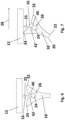
- the wiper blade 10 according to the invention is made of Figure 2 shown in an operating position.
- the wiper blade 10 which is pressed onto the windshield 30 by the moving wiper arm, is dragged by its spring rail 12 over the windshield 30 in the direction of the directional arrow 28. Due to the adhesion or friction between the windshield 30 and the wiper strip 18, the latter tilts by an angle ⁇ , so that only the second wiping edge 22 rests on the windshield 30.
- the tilting web element 16, in particular the web 25 of the tilting web element 16, is now slightly elastically deformed.
- the wiper strip is essentially triangular in shape. Opposite, i.e., on the side of the wiper strip 18 that is adjacent to the spring rail 12, are the two other corners of the essentially triangular wiper strip 18, forming a first stop 32 and a second stop 34.
- the tilting bar element 16 will tilt in the opposite direction.
- the wiper strip 18 will then slide over the window 30 at its first wiping edge 22, and the first stop 32 will limit the tilting of the wiper strip 18 by striking the spring rail 12.
- the tilting web element 16 is in the designs according to Figure 2 and Figure 3 formed integrally with the spring rail 12.
- the spring rail 12 can also be made of plastic, in particular as an injection-molded or extruded part.
- FIG 4 The wiper blade 10 according to the invention is shown in a further variation in the Figures 2 and 3
- the tilting web element 16, in particular its web 25, is separately attached to a casing 36 that surrounds the spring rail 12, which is made of metal here.
- This casing 36 can be made of plastic, for example, and essentially enclose the spring rail 12, which is made of steel here.
- the tilting web element 16 is welded to the casing 36 using an ultrasonic welding process.
- the tilting web element 16 can also be glued or attached to the casing 36 by another material-locking method.
- a direct connection to the spring rail 12 is also possible.
- the tilting bar element 16 can also be glued, welded, riveted, or screwed directly to the spring rail 12.
- a plug-in or rail connection is also possible.
- the tilting bar element 16 has Figure 4 a surface element 38 that enlarges the contact surface between the tilting web element 16 and the casing 36 or spring rail 12. This is particularly advantageous in the case of an adhesive connection or a welded connection between the web 25 and the spring rail 12.
- the tilting web element 16 is formed integrally with the casing 36, which essentially completely encloses the spring rail 12.
- the tilting web element 16 is typically made of plastic and is manufactured, for example, by extrusion or injection molding.
- the spring rail 12 can also be provided with a plastic layer that essentially completely coats it.
- the positive locking element 24 and the counter-locking element 26 are designed such that they form a joint, so that an articulated connection is formed between the tilting web element 16, at the end of which the positive locking element 24 is arranged, and the wiper strip 18, which has the counter-locking element 26 designed as a recess.
- the tilting web element 16 is only slightly elastic to rigid, since the mobility of the wiper strip 18 is realized by the articulated connection between the positive locking element 24 and the counter-locking element 26.
- the positive locking element 24 is round in cross-section.
- the counter-locking element 26 is designed as a round recess which has approximately the same diameter as the form-locking element 24.
- the form-locking element 24 is attached to the end of the web 25, as in the previous embodiments.
- the counter-locking element 26 forms the tip of a V-shaped cutout which is formed by a first stop wall 40 and a second stop wall 42, in such a way that a keyhole-like cross-section with an undercut connection is created. In this way, the form-locking element 24, which is round in cross-section, can be easily inserted into the wiper strip 18.
- the first stop wall 40 and the second stop wall 42 simultaneously form stops for limiting the angle ⁇ ( Figure 3 ). The exact function of these limits or stops is explained in Figure 7 described.
- the form-locking element 24, as already described above, has a round cross-section.
- the mating locking element 26, and thus the recess in the wiper strip 18, is also designed as a round recess, which is located approximately centrally in the wiper strip 18 in cross-section.
- the V-shaped notch is provided for inserting the form-locking element 24, so that the form-locking element 24 arranged at the free end of the web 25 can be inserted into the wiper strip 18, in particular the mating locking element 26.
- the V-shaped notch is formed by the first stop wall 40 and the second stop wall 42. The distance between the first stop wall 40 and the second stop wall 42 in the area of the mating locking element 26 is smaller than the diameter of the round mating locking element 26, creating an undercut and securely holding the wiper strip 18 on the tilting web element 16.
- the wiper strip 18 is tilted to the side by the dragging of the wiper blade 10 or the spring rail 12 of the wiper blade 10 in the direction of the arrow 28. Now the second wiping edge 22 rests on the windscreen 30. Since the Since the positive locking element 24 together with the counter-locking element 26 form an articulated connection, the tilting web element 16, or the web 25 of the tilting web element 16, is only slightly tilted. Due to the articulated connection between the tilting web element 16 and the wiper strip 18, the second stop wall 42 now touches the web 25 of the tilting web element 16 and thus limits the angle ⁇ between the tilting web element 16 and the wiper strip 18. The slight tilting or elastic bending of the web 25 of the tilting web element 16 means that the angle ⁇ is still limited by the second stop 34, which strikes the spring rail 12.
- the positive locking element 24 and the counter-locking element 26 interact in a hinge-like manner, so that the first wiping edge 20 rests on the pane 30 and the web 25 of the tilting web element 16 touches the first stop wall 40. Further deflection is limited by the tilting web element 16 or by elastic deformation of the web 25 of the tilting web element 16 to the extent that the first stop 32 strikes the spring rail 12.
- the tilting web element 16 is of essentially elongated shape and has essentially the length of the spring rail 12 ( Figure 1 ). Since the wiper blade has to adapt to the surface of the windscreen 30 along its longitudinal extent, mobility along the longitudinal extent of the tilting web element is required. To improve this mobility, Incisions 44 are provided which extend transversely to the longitudinal extent, starting from the form-locking element 24 in the direction of the webs 25. The incisions 44 are regularly spaced, but in a variation they can also be spaced differently, in particular reduced at the ends of the wiper blade 10, thus providing fewer incisions or more widely spaced incisions in the region of the ends of the wiper blade 10.
- the tilting bar element 16 is generally formed as a plastic part made of a thermoplastic polymer. Additionally, the tilting bar element 16 may have a wind deflector element on the side facing away from the wiper strip 18. In such a configuration, the wind deflector element may be arranged above the spring rail 12, but also below the spring rail 12, or directly in front of the spring rail 12. Such a tilting bar element 16 may, for example, enclose the spring rail 12, as shown, for example, in Figure 5 shown, and in addition to the casing 36, the web 25, and the form-fitting element 24, comprise the wind deflector element in one piece. Such a tilting web element 16 can be easily manufactured using an extrusion process. However, the wind deflector element can also be attached as a separate part to the tilting web element 16 or to the spring rail 12, for example, glued or welded.
Landscapes
- Engineering & Computer Science (AREA)
- Mechanical Engineering (AREA)
- Window Of Vehicle (AREA)
- Injection Moulding Of Plastics Or The Like (AREA)
- Pivots And Pivotal Connections (AREA)
Description
- Die Erfindung betrifft ein Wischblatt, insbesondere für eine Scheibe eines Kraftfahrzeugs, nach Gattung des unabhängigen Anspruchs.
- Es sind schon zahlreiche Wischblätter für Kraftfahrzeuge bekannt, die eine Federschiene aufweisen, an der ein Haltemittel zur Befestigung an einem Wischarm angeordnet ist. Diese Wischblätter umfassen darüber hinaus eine Wischleiste und ein Kippstegelement.
- Derartige Wischblätter sind jedoch aufwendig in der Fertigung und relativ kostenintensiv. Aufgabe der Erfindung ist es daher, ein einfacheres und kostengünstigeres Wischblatt herzustellen.
- Weiterer Stand der Technik ist aus der
US 5,568,670 und derWO 2013/087289 A1 bekannt. - Das erfindungsgemäße Wischblatt mit den Merkmalen des Hauptanspruchs hat den Vorteil, dass das Kippstegelement formschlüssig an der Wischleiste, sowie an der Federschiene befestigt ist und dadurch die Federschiene mit der Wischleiste verbindet.
- Auf diese Weise ist ein einfaches und kostengünstiges Wischblatt gegeben, welches darüber hinaus bei verschiedensten Temperaturen ein gleichmäßiges und optimales Wischbild erzeugt.
- Durch die in den Unteransprüchen aufgeführten Maßnahmen ergeben sich vorteilhafte Weiterbildungen und Verbesserungen der im Hauptanspruch angegebenen Merkmale.
- Nach der Erfindung weist die Wischleiste eine erste Wischkante und eine zweite Wischkante auf und im Betrieb legt durch Verformung des Kippstegelements jeweils nur die erste Wischkante oder die zweite Wischkante auf der Scheibe auf.
- Weiterhin ist es vorteilhaft, wenn das Kippstegelement ein Formschlusselement aufweist, das mit einem Gegenschlusselement der Wischleiste zur Befestigung zusammenwirkt. Auf diese Weise ist eine einfache Ausbildung des Wischblatts gewährleistet.
- Erfindungsgemäß ist die Wischleiste und das Kippstegelement gelenkig miteinander verbunden. Hierbei ist es von besonderem Vorteil, dass dadurch die erste Wischkante und die zweite Wischkante zuverlässig auf der Scheibe aufliegen.
- Hierbei ist es von besonderem Vorteil, wenn das Formschlusselement des Kippstegelements und das Gegenschlusselement der Wischleiste eine gelenkige Verbindung bilden.
- Eine besonders einfache und kostengünstige und daher vorteilhafte Ausbildung ergibt sich dadurch, dass das Kippstegelement an der Federschiene form- und/oder stoffschlüssig befestigt ist.
- Ein besonders gutes Wischbild wird erzielt, wenn das Kippstegelement und die Wischleiste aus verschiedenen Materialien ausgebildet sind. Insbesondere kann auf diese Weise für die jeweiligen Funktionen, also das zuverlässige Kippen einerseits und das saubere Wischen andererseits, jeweils ein optimales Material ausgewählt werden.
- Nach der Erfindung ummantelt das Kippstegelement die Federschiene, so dass sich eine einfache und kostengünstige Ausbildung ergibt.
- Idealerweise ist das Kippstegelement aus thermoplastischem Polymer ausgebildet. Insbesondere wird auf diese Weise im gesamten Temperaturspektrum des Betriebs des Wischblatts ein optimales Wischergebnis erzielt.
- Nach der Erfindung ist das Kippstegelement einstückig mit einem Windabweiselement ausgebildet.
- Verschiedene Ausführungsbeispiele der Erfindung sind in den Zeichnungen dargestellt und in der nachfolgenden Beschreibung näher erläutert. Er zeigen:
-
Figur 1 ein erfindungsgemäßes Wischblatt in einer schematischen Seitenansicht. -
Figuren 2 bis 7 Querschnitte durch erfindungsgemäße Wischblätter, sowie -
Figuren 8 und 9 eine Seitenansicht durch ein Kippstegelement eines erfindungsgemäßen Wischblatt. - In
Figur 1 ist ein erfindungsgemäßes Wischblatt 10 in einer schematischen Seitenansicht gezeigt. - Das Wischblatt 10 umfasst eine Federschiene 12, die ein Haltemittel 14 zur Befestigung an einem Wischerarm, der hier aus Gründen der Übersichtlichkeit nicht gezeichnet ist, ausweist. Das Haltemittel 14 ist entlang der Längserstreckung des Wischblatts 10 etwa mittig angeordnet. Auf der dem Haltemittel 14 abgewandten Seite der Federschiene 12 ist ein Kippstegelement 16 angeordnet, das sich im Wesentlichen über die gesamte Länge des Wischblatts 10, beziehungsweise der Federschiene 12, erstreckt.
- Auf der der Federschiene 12 abgewandten Seite des Kippstegelements 16 ist formschlüssig mit dem Kippstegelement 16 eine Wischleiste 18 verbunden, die nach der Montage auf einem Kraftfahrzeug, auf einer Scheibe 30 (
Figur 3 ) des Kraftfahrzeugs, insbesondere der Windschutzscheibe, aufliegt. - Die Federschiene 12 ist aus einem länglichem Bandstahl gefertigt und vorgebogen, so dass sie in relaxiertem Zustand konvex gebogen ist. Die Vorbiegung ist derart, dass dann, wenn das Wischblatt 10 durch den am Haltemittel 14 befestigten Wischerarm auf die Scheibe 30 gedrückt wird, eine gleichmäßige Auflage der Wischleiste 16 über ihre gesamte Länge auf der Scheibe 30 erzielt wird. Dies wird dadurch erzielt, daß die Vorbiegung der Federschiene 12 stärker ist, als die Krümmung der Scheibe 30 des Kraftfahrzeugs. Dadurch entsteht beim Aufdrücken des Wischblatts 10 durch den Wischerarm auf die Scheibe 30 eine Vorspannung der Federschiene 12, die die Wischleiste 18 entlang ihrer Längserstreckung gleichmäßig auf die Scheibe 30 drückt.
- In
Figur 2 ist eine schematische Querschnittdarstellung eines erfindungsgemäßen Wischblatts 10 gezeigt. - Die Wischleiste 18 ist aus Gummi, insbesondere EDPM oder Naturkautschuk gefertigt und vom im Wesentlichen dreieckiger Gestalt. Auf seiner, der Federschiene 12 abgewandten Seite, die eine Spitze der dreieckigen Gestalt bildet, sind Wischkanten, mithin eine erste Wischkante 20 und eine zweiten Wischkante 22 ausgebildet, die im Betrieb durch Verformung des Kippstegelements 16 auf der hier nicht gezeigten Scheibe 30, aufliegen. Hierzu ist, im Querschnitt betrachtet, die untere Ecke des Dreiecks abgeschnitten, so daß die im Wesentlichen dreieckige Gestalt im Bereich dieser Ecke anstatt einer Ecke zwei nahe beieinanderliegende Ecken aufweist, die die erste Wischkante 20 und die zweite Wischkante 22 bilden.
- Die Wischleiste 18 ist durch das Kippstegelement 16 an der Federschiene 12 befestigt. Zur Befestigung der Wischleiste 18 an der Federschiene 12 weist das Kippstegelement 16 ein Formschlusselement 24 und einen Steg 25 auf. Das Formschlusselement 24 wirkt mit einem Gegenschlusselement 26 in der Wischleiste 18 zusammen und bildet mit diesem eine Formschlussverbindung. Das Kippstegelement 16 ist von im Querschnitt länglicher Gestalt und erstreckt sich ausgehend von der Federschiene 12 in Richtung der Wischleiste 18 und dringt in die Wischleiste 18 ein. Insbesondere ist der Steg 25 des Kippstegelements 16 im Querschnitt betrachtet an einem Ende an der Federschiene 12 befestigt und anderen, freien Ende des Stegs 25 ist das Formschlusselement 24 angeordnet, das im Querschnitt eine im wesentlichen dreieckige Gestalt aufweist. Eines der spitzen Enden des im Querschnitt dreieckigen Formschlusselements 24 ist der Wischleiste 18 zugewandt.
- Als Gegenschlusselement 26 ist in der Wischleiste 18 eine zur Form des Formschlusselements 24 entsprechende Aussparung vorgesehen, die das Gegenschlusselement 26 bildet. Die im Wesentlichen dreieckige Ausbildung des Formschlusselements 24 ermöglicht, dass die Wischleiste bei der Montage einfach auf das Kippstegelement 16 aufgesteckt werden kann und sich dadurch eine sichere Verbindung zwischen Kippstegelement 16 und Wischleiste 18 ergibt, die nur mit hohem Kraftaufwand lösbar ist. Dies wird dadurch erzielt, dass die breite Seite des dreieckigen Formschlusselements 24 mit dem Steg 25 verbunden ist, der ebenso in die Wischleiste 18 eindringt. Auf diese Weise ergibt sich eine Hinterschnitt-Verbindung zwischen Wischleiste 18 und Kippstegelement 16.
- In
Figur 3 ist das erfindungsgemäße Wischblatt 10 ausFigur 2 in einer Betriebsstellung gezeigt. Das Wischblatt 10, das durch den sich bewegenden Wischerarm auf die Scheibe 30 gedrückt wird, wird mit seiner Federschiene 12 über die Scheibe 30 in Richtung des Richtungspfeils 28 geschleppt. Aufgrund der Haftung bzw. Reibung zwischen der Scheibe 30 und der Wischleiste 18 kippt diese um einen Winkel α, so dass lediglich die zweite Wischkante 22 auf der Scheibe 30 aufliegt. Das Kippstegelement 16, besondere der Steg 25 des Kippstegelements 16, ist nun leicht elastisch verformt. - Wie auch in
Figur 2 zu sehen, ist die Wischleiste von im Wesentlichen dreieckiger Gestalt. Gegenüberliegend, also auf der Seite der Wischleiste 18, die benachbart zur Federschiene 12 angeordnet ist, sind die zwei weiteren Ecken, der im Wesentlichen dreieckigen Wischleiste 18 und bilden einen ersten Anschlag 32 und einen zweiten Anschlag 34. - Die elastische Verformung des Kippstegelements 16 geht hier nun so weit, dass der zweite Anschlag 34 an der Federschiene 12 anschlägt und somit ein weiteres Verkippen der Wischleiste 18 verhindert.
- Verläuft die Wischrichtung entgegen dem Richtungspfeil 28, so wird sich das Kippstegelement 16, mithin der Steg 25, in die entgegengesetzte Richtung verkippen. Die Wischleiste 18 wird dann an seiner ersten Wischkante 22 über die Scheibe 30 gleiten und der erste Anschlag 32 wird die Verkippung der Wischleiste 18 durch Anschlagen an der Federschiene 12, begrenzen.
- Das Kippstegelement 16 ist bei den Ausbildungen gemäß
Figur 2 und Figur 3 einstückig mit der Federschiene 12 ausgebildet. Bei dieser Ausbildung kann die Federschiene 12 auch aus Kunststoff ausgebildet sein, insbesondere als Spritzguss- oder Extrusionsteil. - In
Figur 4 ist das erfindungsgemäße Wischblatt 10 in einer weiteren Variation aus denFiguren 2 und 3 dargestellt. Im Gegensatz zuFigur 2 und Figur 3 ist das Kippstegelement 16, insbesondere dessen Steg 25, hier separat an einer Ummantelung 36 befestigt, die die Federschiene 12, die hier aus Metall ausgebildet ist, ummantelt. Diese Ummantelung 36 kann bspw. aus Kunststoff ausgebildet sein und die Federschiene 12, die hier aus Stahl ausgebildet ist, im Wesentlichen umschließen. Das Kippstegelement 16 ist hierbei über ein Ultraschallschweißverfahren an der Ummantelung 36 angeschweisst. - In einer Variation kann das Kippstegelement 16 jedoch auch angeklebt oder durch ein anderes stoffschlüssiges Verfahren an der Ummantelung 36 befestigt sein.
- In einer weiteren Variation ist auch eine direkte Verbindung an der Federschiene 12 möglich. So kann das Kippstegelement 16 auch direkt an die Federschiene 12 angeklebt, angeschweisst, vernietet oder verschraubt sein. Auch eine Steck- oder Schienenverbindung ist hier möglich.
- Zur Verbesserung der Befestigung des Kippstegelements 16 an der Federschiene 12 bzw. deren Ummantelung 36 weist das Kippstegelement 16 in
Figur 4 ein Flächenelement 38 auf, das die Anlagefläche zwischen Kippstegelement 16 und Ummantelung 36 bzw. Federschiene 12 vergrößert. Besonders bei einer Klebeverbindung oder einer Schweißverbindung zwischen Steg 25 und Federschiene 12 ist dies vorteilhaft. - In
Figur 5 ist eine weitere Variation der Erfindung dargestellt. Das Kippstegelement 16 ist hier einstückig mit der Ummantelung 36 ausgebildet, die die Federschiene 12 im Wesentlichen vollständig ummantelt. Das Kippstegelement 16 ist hierbei typischerweise aus Kunststoff ausgebildet und bspw. im Extrusions- oder Spritzgussverfahren hergestellt. Wie eben den vorangegangenen Ausführungsbeispielen kann die Federschiene 12 auch mit einer Kunststoffschicht versehen sein, die diese im Wesentlichen vollständig beschichtet. - Im Folgenden werden jeweils nur die Unterschiede zu
Figuren 2 und 3 beschrieben, so dass die Ausführungen ausFiguren 2 und 3 für die folgenden Ausführungen weitergelten. - In
Figur 6 ist eine weitere Variation eines verbindungsgemäßen Wischblatts 10 beschrieben. Wie inFiguren 2 und 3 ist auch hier das Kippstegelement 16 einstückig mit der Federschiene 12 ausgebildet. In einer Variation kann jedoch auch bei einer Ausbildung nachFigur 6 das Kippstegelement wie in denFiguren 4 und 5 gezeigt, ausgebildet sein. - In der Ausführungsform aus
Figur 6 ist lediglich die Ausführung des Formschlusselements 24 und des Gegenschlusselements 26 anders als in den vorangegangenenFiguren 2 bis 5 . Bei dieser Ausführungsform ist das Formschlusselement 24 und das Gegenschlusselement 26 derart ausgebildet, dass diese ein Gelenk bilden, so dass eine gelenkige Verbindung zwischen dem Kippstegelement 16, an dessen Ende des Formschlusselement 24 angeordnet ist und der Wischleiste 18, die die als Aussparung ausgebildete Gegenschlusselement 26 aufweist, gebildet ist. Das Kippstegelement 16 ist hier nur wenig elastisch bis starr, da die Beweglichkeit der Wischleiste 18 durch die gelekige Verbidung zwischen Formschlusselement 24 und Gegenschlusselement 26 verwirklicht ist. Hierzu ist das Formschlusselements 24 im Querschnitt rund ausgebildet und entsprechend das gegen Schlusselement 26 als runde Aussparung ausgebildet, die etwa den gleichen Durchmesser wie das Formschlusselements 24 aufweist. Das Formschlusselement 24 ist am Ende des Stegs 25, wie in den vorangegangenen Ausführungsbeispielen, befestigt. Das Gegenschlusselement 26 bildet die Spitze eines V-förmige Ausschnitts der durch eine erste Anschlagswand 40 und eine zweite Anschlagswand 42 gebildet ist und zwar derart, dass eine im Querschnitt schlüssellochartige Ausbildung mit einer Hinterschnitt-Verbindung entsteht. Auf diese Weise lässt sich das im Querschnitt runde Formschlusselements 24 leicht in die Wischleiste 18 einfügen. Die erste Anschlagswand 40 und die zweite Anschlagswand 42 bilden gleichzeitig Anschläge zur Begrenzung des Winkels α (Figur 3 ). Die genaue Funktion dieser Begrenzungen bzw. Anschläge wird inFigur 7 beschrieben. - Das Formschlusselement 24 ist, wie oben bereits beschrieben, im Querschnitt rund. Korrespondierend dazu ist auch das Gegenschlusselement 26, mithin die Aussparung in der Wischleiste 18 als runde Aussparung ausgebildet, die etwa im Querschnitt mittig in der Wischleiste 18 sitzt. Zum Einfügen des Formschlusselements 24 ist der V-förmige Einschnitt vorgesehen, sodass das am freien Ende des Stegs 25 angeordnete Formschlusselement 24 in die Wischleiste 18, insbesondere das gegen Schlusselement 26, eingeführt werden kann. Der V-förmige Einschnitt ist durch die erste Anschlagswand 40 und die zweite Anschlagswand 42 gebildet. Der Abstand zwischen der ersten Anschlagswand 40 und der zweiten Anschlagswand 42 ist im Bereich des Gegenschlusselements 26 kleiner als der Durchmesser des runden Gegenschlusselements 26, sodass ein Hinterschnitt entsteht und die Wischleiste 18 dadurch sicher am Kippstegelements 16 gehaltert ist.
- In
Figur 7 ist die Ausbildung des Wischblatts 10 ausFigur 6 im Betrieb gezeigt. Wie auch in den vorhergehenden Zeichnungen werden nur die Unterschiede zu den anderen Ausführungsbeispielen erläutert. Die Ausführungen im Hinblick auf die anderen Ausführungsbeispiele gelten daher ansonsten auch für dieses. - Die Wischleiste 18 ist durch das Schleppen des Wischblatts 10 bzw. der Federschiene 12 des Wischblatts 10 in Richtung des Richtungspfeils 28 zur Seite gekippt. Nun liegt die zweite Wischkante 22 auf der Scheibe 30 auf. Da das Formschlusselement 24 zusammen mit dem Gegenschlusselement 26 eine gelenkige Verbindung bilden, ist das Kippstegelement 16, bzw. der Steg 25 des Kippstegelements 16 nur wenig verkippt. Durch die gelenkige Verbindung zwischen Kippstegelement 16 und Wischleiste 18 berührt nun die zweite Anschlagswand 42 den Steg 25 des Kippstegelements 16 und begrenzt somit den Winkel α zwischen Kippstegelement 16 und Wischleiste 18. Das leichte Verkippen bzw. elastische Verbiegen des Stegs 25 des Kippstegelements 16 ist der Winkel α weiterhin durch den zweiten Anschlag 34 begrenzt, der an der Federschiene 12 anschlägt.
- Bei einem Wechsel der Bewegungsrichtung, entgegen dem Richtungspfeil 28 werden das Formschlusselement 24 und das Gegenschlusselement 26 scharnierartig zusammenwirken, so dass die erste Wischkante 20 auf der Scheibe 30 aufliegt und der Steg 25 des Kippstegelements 16 die erste Anschlagswand 40 berührt. Ein weiteres Auslenken wird durch das Kippstegelement 16 bzw. durch elastische Verformung des Stegs 25 des Kippstegelements 16 soweit begrenzt, als das der erste Anschlag 32 an der Federschiene 12 anschlägt.
- Nach der Erfindung ist die Ausbildung aus
Figuren 6 und 7 mit den Ausführungen vonFiguren 4 oder 5 kombiniert , so dass das Kippstegelement 16 an der Ummantelung 36 der Federschiene 12 angeordnet ist. Der erste Anschlag 32 und der zweite Anschlag 24 berühren dann nicht das Federelement selbst sondern die Ummantelung 36. Um Wiederholungen zu vermeiden wir hierzu auf die vorangegangenenFiguren 4 und 5 verwiesen, deren Ausbildung auf die Ausbildung vonFiguren 6 und 7 übertragen werden kann. - In
Figur 8 und Figur 9 ist das Kippstegelement 16 eines erfindungsgemäßen Wischblatts in einer schematischen Seitenansicht gezeigt. - Das Kippstegelement 16 ist von im Wesentlichen länglicher Gestalt und weist im Wesentlichen die Länge der Federschiene 12 (
Figur 1 ) auf. Da sich das Wischblatt entlang seiner Längserstreckung der Scheibenoberfläche der Scheibe 30 anzupassen hat, ist eine Beweglichkeit entlang der Längserstreckung des Kippstegelements erforderlich. Zur Verbesserung dieser Beweglichkeit sind Einschnitte 44 vorgesehen, die sich quer zu Längserstreckung, ausgehend vom Formschlusselement 24 in Richtung der Stege 25 erstrecken. Die Einschnitte 44 sind hierbei regelmäßig beabstandet, können in einer Variation jedoch auch unterschiedlich beabstandet sein, insbesondere an den Enden des Wischblatts 10 reduziert sein, mithin weniger Einschnitte bzw. größer beabstandete Einschnitte im Bereich der Enden des Wischblattes 10 vorgesehen sein. - In einer Variation ist es auch möglich, die Einschnitte ausgehend von Flächenelement 38 in Richtung des Formschlusselements 24 vorzusehen. Dies ist insbesondere dann sinnvoll, wenn das Kippstegelement 16 beweglich an der Federschiene 12, bspw. durch eine Kederschiene befestigt ist.
Figur 9 zeigt das Kippstegelement 16 ausFigur 8 in einer gebogenen, mithin der relaxierten Form der Federschiene 12 angepassten Form. - Das Kippstegelement 16 ist in der Regel als Kunststoffteil aus einem thermoplastischen Polymer ausgebildet. Ergänzend kann auf der der Wischleiste 18 abgewandten Seite das Kippstegelement 16 ein Windabweiselement aufweisen. Das Windabweiselement kann bei einer derartigen Ausgestaltung oberhalb der Federschiene 12, aber auch unterhalb der Federschiene 12 oder direkt vor der Federschiene 12 angeordnet sein. Ein derartiges Kippstegelement 16 kann beispielsweise die Federschiene 12 ummanteln, wie beispielsweise in
Figur 5 gezeigt, und neben der Ummantelung 36, dem Steg 25 und dem Formschlusselement 24 einstückig das Windabweiselement aufweisen. Ein derartiges Kippstegelement 16 kann in einfacher Weise durch ein Extrusionsverfahren hergestellt werden. Das Windabweiselement kann aber auch als separates Teil am Kippstegelement 16 oder an der Federschiene 12 befestigt, beispielsweise angeklebt oder angeschweisst, sein.
Claims (6)
- Wischblatt (10), insbesondere für eine Scheibe (30) eines Kraftfahrzeugs, umfassend eine Federschiene (12), an der ein Haltemittel (14) zur Befestigung an einem Wischerarm angeordnet ist, eine Wischleiste (18) und ein Kippstegelement (16), wobei das Kippstegelement (16) formschlüssig an der Wischleiste (18) befestigt ist, sowie an der Federschiene (12) befestigt ist und dadurch die Federschiene (12) mit der Wischleiste (18) verbindet, wobei die Wischleiste (18) und das Kippstegelement (16) gelenkig verbunden sind, wobei die Wischleiste (18) eine erste Wischkante (20) und eine zweite Wischkante (22) aufweist und im Betrieb durch Verformung des Kippstegelements (16) jeweils nur die erste Wischkante (20) oder die zweite Wischkante (22) auf der Scheibe (30) aufliegt, dadurch gekennzeichnet dass das Kippstegelement (16) die Federschiene (12) zumindest teilweise, insbesondere vollständig, ummantelt, und das Kippstegelement (16) einstückig mit einem Windabweiselement ausgebildet ist.
- Wischblatt (10) nach Anspruch 1, dadurch gekennzeichnet, dass das Kippstegelement (16) ein Formschlußelement (24) aufweist, das mit einem Gegenschlußelement (26) der Wischleiste (18) zur Befestigung zusammenwirkt.
- Wischblatt (10) nach Anspruch 2, dadurch gekennzeichnet, dass Formschlußelement (24) und Gegenschlußelement (26) eine gelenkige Verbindung bilden.
- Wischblatt (10) nach einem der vorhergehenden Ansprüche, dadurch gekennzeichnet, dass das Kippstegelement (16) an der Federschiene (12) form- oder stoffschlüssig befestigt ist.
- Wischblatt (10) nach einem der vorhergehenden Ansprüche, dadurch gekennzeichnet, dass Kippstegelement (16) und Wischleiste (18) aus verschiedenen Materialien ausgebildet sind.
- Wischblatt (10) nach einem der vorhergehenden Ansprüche, dadurch gekennzeichnet, dass das Kippstegelement (16) aus thermoplastischem Polymer ausgebildet ist.
Applications Claiming Priority (2)
| Application Number | Priority Date | Filing Date | Title |
|---|---|---|---|
| DE102019210730.3A DE102019210730A1 (de) | 2019-07-19 | 2019-07-19 | Wischblatt, insbesondere für eine Scheibe eines Kraftfahrzeugs |
| PCT/EP2020/069720 WO2021013600A1 (de) | 2019-07-19 | 2020-07-13 | Wischblatt, insbesondere für eine scheibe eines kraftfahrzeugs |
Publications (2)
| Publication Number | Publication Date |
|---|---|
| EP3999386A1 EP3999386A1 (de) | 2022-05-25 |
| EP3999386B1 true EP3999386B1 (de) | 2025-06-25 |
Family
ID=71608005
Family Applications (1)
| Application Number | Title | Priority Date | Filing Date |
|---|---|---|---|
| EP20739985.8A Active EP3999386B1 (de) | 2019-07-19 | 2020-07-13 | Wischblatt, insbesondere für eine scheibe eines kraftfahrzeugs |
Country Status (3)
| Country | Link |
|---|---|
| EP (1) | EP3999386B1 (de) |
| DE (1) | DE102019210730A1 (de) |
| WO (1) | WO2021013600A1 (de) |
Families Citing this family (2)
| Publication number | Priority date | Publication date | Assignee | Title |
|---|---|---|---|---|
| CN115139987B (zh) * | 2022-07-12 | 2024-09-27 | 都昌县业达汽车零部件有限公司 | 一种柔性雨刷及雨刮器 |
| DE102023211774A1 (de) * | 2023-11-27 | 2025-05-28 | Robert Bosch Gesellschaft mit beschränkter Haftung | Wischblatt und Wischblattwechselelement |
Family Cites Families (6)
| Publication number | Priority date | Publication date | Assignee | Title |
|---|---|---|---|---|
| US3031709A (en) * | 1956-04-24 | 1962-05-01 | Gen Motors Corp | Windshield wiper blade |
| US5568670A (en) * | 1992-06-29 | 1996-10-29 | Samples; Timothy W. | Wiper blade with wire elastic response member therein |
| FR2705299B1 (fr) * | 1993-05-17 | 1995-07-07 | Valeo Systemes Dessuyage | Lame d'essuie-glace à deux pièces coextrudées et balai d'essuie-glace équipé d'une telle lame. |
| DE19745003A1 (de) * | 1997-10-11 | 1999-04-29 | Bosch Gmbh Robert | Wischergummi |
| DE102009001043A1 (de) * | 2009-02-20 | 2010-08-26 | Robert Bosch Gmbh | Wischerblatt für einen Scheibenwischer sowie Verfahren zu seiner Herstellung |
| DE102011088750A1 (de) * | 2011-12-15 | 2013-06-20 | Robert Bosch Gmbh | Wischleistenvorrichtung |
-
2019
- 2019-07-19 DE DE102019210730.3A patent/DE102019210730A1/de active Pending
-
2020
- 2020-07-13 EP EP20739985.8A patent/EP3999386B1/de active Active
- 2020-07-13 WO PCT/EP2020/069720 patent/WO2021013600A1/de not_active Ceased
Also Published As
| Publication number | Publication date |
|---|---|
| DE102019210730A1 (de) | 2021-01-21 |
| EP3999386A1 (de) | 2022-05-25 |
| WO2021013600A1 (de) | 2021-01-28 |
Similar Documents
| Publication | Publication Date | Title |
|---|---|---|
| EP2917076B1 (de) | Scheibenwischvorrichtung für ein fahrzeug | |
| EP1732792B1 (de) | Wischblatt | |
| EP2015971B1 (de) | Wischblatt | |
| EP2162321B1 (de) | Flaches wischblatt | |
| DE102011100931B4 (de) | Wischerblatt | |
| EP1740424B1 (de) | Wischblatt | |
| EP1375273B1 (de) | Scheibenwischvorrichtung | |
| DE10207706A1 (de) | Wischblatt zum Reinigen von Scheiben insbesondere von Kraftfahrzeugen | |
| EP3999386B1 (de) | Wischblatt, insbesondere für eine scheibe eines kraftfahrzeugs | |
| DE102008041077A1 (de) | Wischleiste | |
| DE10122637B4 (de) | Dichtungsanordnung für eine Kraftfahrzeugtüre und/oder ein Kraftfahrzeugfenster | |
| DE102012100779B4 (de) | Wischblatt zum Reinigen von Fahrzeugscheiben | |
| EP3172095A1 (de) | Quickfix für finray-wischer | |
| WO2011101062A1 (de) | Wischblatteinheit | |
| EP3044051B1 (de) | Filmscharnier für eine scheibenwischvorrichtung | |
| WO2009068266A1 (de) | Wischelement und wischerblatt für ein fahrzeug | |
| DE102017113632B4 (de) | Scheibenwischer | |
| DE10333082B4 (de) | Wischblatt für Fahrzeugscheiben | |
| DE102016226269A1 (de) | Flachbalkenwischblatt | |
| EP2720915B1 (de) | Wischblatt zum reinigen von scheiben insbesondere von kraftfahrzeugen | |
| EP2135781A2 (de) | Federleiste, Herstellverfahren und Wischer für die Reinigung insbesondere einer Fahrzeugscheibe | |
| EP1816043B1 (de) | Wischerarm, insbesondere für ein Kraftfahrzeug | |
| DE102018215994A1 (de) | Flachbalkenwischblatt | |
| EP3921210B1 (de) | Kopplungsvorrichtung | |
| EP2443008B1 (de) | Befestigungselement zur aufnahme eines wischerarmes |
Legal Events
| Date | Code | Title | Description |
|---|---|---|---|
| STAA | Information on the status of an ep patent application or granted ep patent |
Free format text: STATUS: UNKNOWN |
|
| STAA | Information on the status of an ep patent application or granted ep patent |
Free format text: STATUS: THE INTERNATIONAL PUBLICATION HAS BEEN MADE |
|
| PUAI | Public reference made under article 153(3) epc to a published international application that has entered the european phase |
Free format text: ORIGINAL CODE: 0009012 |
|
| STAA | Information on the status of an ep patent application or granted ep patent |
Free format text: STATUS: REQUEST FOR EXAMINATION WAS MADE |
|
| 17P | Request for examination filed |
Effective date: 20220221 |
|
| AK | Designated contracting states |
Kind code of ref document: A1 Designated state(s): AL AT BE BG CH CY CZ DE DK EE ES FI FR GB GR HR HU IE IS IT LI LT LU LV MC MK MT NL NO PL PT RO RS SE SI SK SM TR |
|
| DAV | Request for validation of the european patent (deleted) | ||
| DAX | Request for extension of the european patent (deleted) | ||
| STAA | Information on the status of an ep patent application or granted ep patent |
Free format text: STATUS: EXAMINATION IS IN PROGRESS |
|
| 17Q | First examination report despatched |
Effective date: 20231018 |
|
| GRAP | Despatch of communication of intention to grant a patent |
Free format text: ORIGINAL CODE: EPIDOSNIGR1 |
|
| STAA | Information on the status of an ep patent application or granted ep patent |
Free format text: STATUS: GRANT OF PATENT IS INTENDED |
|
| INTG | Intention to grant announced |
Effective date: 20250313 |
|
| GRAS | Grant fee paid |
Free format text: ORIGINAL CODE: EPIDOSNIGR3 |
|
| GRAA | (expected) grant |
Free format text: ORIGINAL CODE: 0009210 |
|
| STAA | Information on the status of an ep patent application or granted ep patent |
Free format text: STATUS: THE PATENT HAS BEEN GRANTED |
|
| AK | Designated contracting states |
Kind code of ref document: B1 Designated state(s): AL AT BE BG CH CY CZ DE DK EE ES FI FR GB GR HR HU IE IS IT LI LT LU LV MC MK MT NL NO PL PT RO RS SE SI SK SM TR |
|
| REG | Reference to a national code |
Ref country code: GB Ref legal event code: FG4D Free format text: NOT ENGLISH |
|
| REG | Reference to a national code |
Ref country code: CH Ref legal event code: EP |
|
| REG | Reference to a national code |
Ref country code: CH Ref legal event code: EP |
|
| REG | Reference to a national code |
Ref country code: IE Ref legal event code: FG4D Free format text: LANGUAGE OF EP DOCUMENT: GERMAN |
|
| REG | Reference to a national code |
Ref country code: DE Ref legal event code: R096 Ref document number: 502020011295 Country of ref document: DE |
|
| PG25 | Lapsed in a contracting state [announced via postgrant information from national office to epo] |
Ref country code: FI Free format text: LAPSE BECAUSE OF FAILURE TO SUBMIT A TRANSLATION OF THE DESCRIPTION OR TO PAY THE FEE WITHIN THE PRESCRIBED TIME-LIMIT Effective date: 20250625 |
|
| PGFP | Annual fee paid to national office [announced via postgrant information from national office to epo] |
Ref country code: DE Payment date: 20250924 Year of fee payment: 6 |
|
| REG | Reference to a national code |
Ref country code: LT Ref legal event code: MG9D |
|
| PG25 | Lapsed in a contracting state [announced via postgrant information from national office to epo] |
Ref country code: NO Free format text: LAPSE BECAUSE OF FAILURE TO SUBMIT A TRANSLATION OF THE DESCRIPTION OR TO PAY THE FEE WITHIN THE PRESCRIBED TIME-LIMIT Effective date: 20250925 Ref country code: GR Free format text: LAPSE BECAUSE OF FAILURE TO SUBMIT A TRANSLATION OF THE DESCRIPTION OR TO PAY THE FEE WITHIN THE PRESCRIBED TIME-LIMIT Effective date: 20250926 |
|
| PG25 | Lapsed in a contracting state [announced via postgrant information from national office to epo] |
Ref country code: BG Free format text: LAPSE BECAUSE OF FAILURE TO SUBMIT A TRANSLATION OF THE DESCRIPTION OR TO PAY THE FEE WITHIN THE PRESCRIBED TIME-LIMIT Effective date: 20250625 |
|
| PG25 | Lapsed in a contracting state [announced via postgrant information from national office to epo] |
Ref country code: HR Free format text: LAPSE BECAUSE OF FAILURE TO SUBMIT A TRANSLATION OF THE DESCRIPTION OR TO PAY THE FEE WITHIN THE PRESCRIBED TIME-LIMIT Effective date: 20250625 |
|
| PGFP | Annual fee paid to national office [announced via postgrant information from national office to epo] |
Ref country code: FR Payment date: 20250804 Year of fee payment: 6 |
|
| PG25 | Lapsed in a contracting state [announced via postgrant information from national office to epo] |
Ref country code: RS Free format text: LAPSE BECAUSE OF FAILURE TO SUBMIT A TRANSLATION OF THE DESCRIPTION OR TO PAY THE FEE WITHIN THE PRESCRIBED TIME-LIMIT Effective date: 20250925 |
|
| PG25 | Lapsed in a contracting state [announced via postgrant information from national office to epo] |
Ref country code: LV Free format text: LAPSE BECAUSE OF FAILURE TO SUBMIT A TRANSLATION OF THE DESCRIPTION OR TO PAY THE FEE WITHIN THE PRESCRIBED TIME-LIMIT Effective date: 20250625 |
|
| REG | Reference to a national code |
Ref country code: NL Ref legal event code: MP Effective date: 20250625 |
|
| PG25 | Lapsed in a contracting state [announced via postgrant information from national office to epo] |
Ref country code: NL Free format text: LAPSE BECAUSE OF FAILURE TO SUBMIT A TRANSLATION OF THE DESCRIPTION OR TO PAY THE FEE WITHIN THE PRESCRIBED TIME-LIMIT Effective date: 20250625 |
|
| PG25 | Lapsed in a contracting state [announced via postgrant information from national office to epo] |
Ref country code: PT Free format text: LAPSE BECAUSE OF FAILURE TO SUBMIT A TRANSLATION OF THE DESCRIPTION OR TO PAY THE FEE WITHIN THE PRESCRIBED TIME-LIMIT Effective date: 20251027 |
|
| PG25 | Lapsed in a contracting state [announced via postgrant information from national office to epo] |
Ref country code: IS Free format text: LAPSE BECAUSE OF FAILURE TO SUBMIT A TRANSLATION OF THE DESCRIPTION OR TO PAY THE FEE WITHIN THE PRESCRIBED TIME-LIMIT Effective date: 20251025 |
|
| PG25 | Lapsed in a contracting state [announced via postgrant information from national office to epo] |
Ref country code: SM Free format text: LAPSE BECAUSE OF FAILURE TO SUBMIT A TRANSLATION OF THE DESCRIPTION OR TO PAY THE FEE WITHIN THE PRESCRIBED TIME-LIMIT Effective date: 20250625 |
|
| PG25 | Lapsed in a contracting state [announced via postgrant information from national office to epo] |
Ref country code: CZ Free format text: LAPSE BECAUSE OF FAILURE TO SUBMIT A TRANSLATION OF THE DESCRIPTION OR TO PAY THE FEE WITHIN THE PRESCRIBED TIME-LIMIT Effective date: 20250625 |
|
| PG25 | Lapsed in a contracting state [announced via postgrant information from national office to epo] |
Ref country code: PL Free format text: LAPSE BECAUSE OF FAILURE TO SUBMIT A TRANSLATION OF THE DESCRIPTION OR TO PAY THE FEE WITHIN THE PRESCRIBED TIME-LIMIT Effective date: 20250625 |
|
| PG25 | Lapsed in a contracting state [announced via postgrant information from national office to epo] |
Ref country code: EE Free format text: LAPSE BECAUSE OF FAILURE TO SUBMIT A TRANSLATION OF THE DESCRIPTION OR TO PAY THE FEE WITHIN THE PRESCRIBED TIME-LIMIT Effective date: 20250625 |
|
| PG25 | Lapsed in a contracting state [announced via postgrant information from national office to epo] |
Ref country code: SK Free format text: LAPSE BECAUSE OF FAILURE TO SUBMIT A TRANSLATION OF THE DESCRIPTION OR TO PAY THE FEE WITHIN THE PRESCRIBED TIME-LIMIT Effective date: 20250625 |
|
| PG25 | Lapsed in a contracting state [announced via postgrant information from national office to epo] |
Ref country code: ES Free format text: LAPSE BECAUSE OF FAILURE TO SUBMIT A TRANSLATION OF THE DESCRIPTION OR TO PAY THE FEE WITHIN THE PRESCRIBED TIME-LIMIT Effective date: 20250625 |