EP3998693A1 - Stator and motor - Google Patents
Stator and motor Download PDFInfo
- Publication number
- EP3998693A1 EP3998693A1 EP20910868.7A EP20910868A EP3998693A1 EP 3998693 A1 EP3998693 A1 EP 3998693A1 EP 20910868 A EP20910868 A EP 20910868A EP 3998693 A1 EP3998693 A1 EP 3998693A1
- Authority
- EP
- European Patent Office
- Prior art keywords
- stator
- phase
- winding
- yoke
- space
- Prior art date
- Legal status (The legal status is an assumption and is not a legal conclusion. Google has not performed a legal analysis and makes no representation as to the accuracy of the status listed.)
- Pending
Links
Images





Classifications
-
- H—ELECTRICITY
- H02—GENERATION; CONVERSION OR DISTRIBUTION OF ELECTRIC POWER
- H02K—DYNAMO-ELECTRIC MACHINES
- H02K1/00—Details of the magnetic circuit
- H02K1/06—Details of the magnetic circuit characterised by the shape, form or construction
- H02K1/12—Stationary parts of the magnetic circuit
- H02K1/14—Stator cores with salient poles
- H02K1/146—Stator cores with salient poles consisting of a generally annular yoke with salient poles
- H02K1/148—Sectional cores
-
- H—ELECTRICITY
- H02—GENERATION; CONVERSION OR DISTRIBUTION OF ELECTRIC POWER
- H02K—DYNAMO-ELECTRIC MACHINES
- H02K1/00—Details of the magnetic circuit
- H02K1/06—Details of the magnetic circuit characterised by the shape, form or construction
- H02K1/12—Stationary parts of the magnetic circuit
- H02K1/16—Stator cores with slots for windings
-
- H—ELECTRICITY
- H02—GENERATION; CONVERSION OR DISTRIBUTION OF ELECTRIC POWER
- H02K—DYNAMO-ELECTRIC MACHINES
- H02K1/00—Details of the magnetic circuit
- H02K1/06—Details of the magnetic circuit characterised by the shape, form or construction
- H02K1/12—Stationary parts of the magnetic circuit
- H02K1/20—Stationary parts of the magnetic circuit with channels or ducts for flow of cooling medium
-
- H—ELECTRICITY
- H02—GENERATION; CONVERSION OR DISTRIBUTION OF ELECTRIC POWER
- H02K—DYNAMO-ELECTRIC MACHINES
- H02K3/00—Details of windings
- H02K3/04—Windings characterised by the conductor shape, form or construction, e.g. with bar conductors
- H02K3/28—Layout of windings or of connections between windings
-
- Y—GENERAL TAGGING OF NEW TECHNOLOGICAL DEVELOPMENTS; GENERAL TAGGING OF CROSS-SECTIONAL TECHNOLOGIES SPANNING OVER SEVERAL SECTIONS OF THE IPC; TECHNICAL SUBJECTS COVERED BY FORMER USPC CROSS-REFERENCE ART COLLECTIONS [XRACs] AND DIGESTS
- Y02—TECHNOLOGIES OR APPLICATIONS FOR MITIGATION OR ADAPTATION AGAINST CLIMATE CHANGE
- Y02T—CLIMATE CHANGE MITIGATION TECHNOLOGIES RELATED TO TRANSPORTATION
- Y02T10/00—Road transport of goods or passengers
- Y02T10/60—Other road transportation technologies with climate change mitigation effect
- Y02T10/64—Electric machine technologies in electromobility
Definitions
- This application relates to the field of motor technology, in particular to a stator and a motor.
- Low-power high-speed motor in the fields of automobiles, home appliances, medical equipment, and robots is becoming more and more extensive, and the requirements for power density are getting higher and higher.
- the power increase mainly depends on the torque increase, and a winding structure with a larger winding coefficient is a key factor.
- the increase of power density is also related to the overall volume of the motor, and reducing a diameter of the stator or shortening an axial length are both key factors.
- the high-speed motor has poor heat dissipation performance due to its high speed, which further limits the power increase of the high-speed motor.
- This application mainly provides a stator and a motor to solve the problem that the output torque and the output power of the motor are not high.
- the stator includes a stator core including a plurality of inner stator teeth and a ring-shaped stator yoke, characterized in that the plurality of inner stator teeth are arranged on an inner side of the stator yoke at intervals along a circumferential direction of the stator yoke, and extend to a central axis of the stator yoke, to form stator slots between adjacent inner stator teeth; and a first phase winding, a second phase winding and a third phase winding, each penetrating through two stator slots which are separated by one stator slot in therebetween, and wound around two adjacent inner stator teeth; characterized in that each of the stator slots is divided into an inner space and an outer space along a radial direction of the stator yoke, each of the first phase winding, the second phase winding and the third phase winding penetrates through inner spaces of the corresponding two stator
- one of the inner space and the outer space of each of the stator slots is penetrated by the first phase winding, the second phase winding, or the third phase winding, and another thereof is in an idle state without being penetrated by any one of the first phase winding, the second phase winding, and the third phase winding.
- the first phase winding includes a first phase inner winding and a first phase outer winding
- the second phase winding includes a second phase inner winding and a second phase outer winding
- the third phase winding includes a third phase inner winding and a third phase outer winding, characterized in that each of the first phase inner winding, the second phase inner winding and the third phase inner winding penetrates through inner spaces of the corresponding two stator slots, and each of the first phase outer winding, the second phase outer winding and the third phase outer winding penetrates through outer spaces of the corresponding two stator slots.
- the first phase inner winding, the second phase inner winding and the third phase inner winding are sequentially staggered with two inner stator teeth along the circumferential direction of the stator yoke; the first phase outer winding, the second phase outer winding and the third phase outer winding are sequentially staggered with two inner stator teeth along the circumferential direction of the stator yoke.
- each of the inner spaces is divided into a first inner sub-space and a second inner sub-space along the circumferential direction of the stator yoke, and each of the first phase inner winding, the second phase inner winding and the third phase inner winding penetrates through a first inner sub-space and a second inner sub-space of the corresponding two stator slots which are adjacent to the wound two inner stator teeth; and each of the outer spaces is divided into a first outer sub-space and a second outer sub-space along the circumferential direction of the stator yoke, each of the first phase outer winding, the second phase outer winding and the third phase outer winding penetrates through a first outer sub-space and a second outer sub-space of the corresponding two stator slots which are adjacent to the wound two inner stator teeth.
- the stator yoke includes a plurality of sub-stator yokes spliced together in sequence, each of the sub-stator yokes is provided with at least two inner stator teeth, two inner stator teeth wound by each of the first phase outer winding, the second phase outer winding and the third phase outer winding are located on the same sub-stator yoke, two inner stator teeth wound by each of the first phase inner winding, the second phase inner winding and the third phase inner winding are located on two adjacent sub-stator yokes.
- a gap is defined between the first phase inner winding and the second phase outer winding and the third phase outer winding along the radial direction of the stator yoke, a gap is defined between the second phase inner winding and the first phase outer winding and the third phase outer winding along the radial direction of the stator yoke, and a gap is defined between the third phase inner winding and the first phase outer winding and the second phase outer winding along the radial direction of the stator yoke.
- two of the first phase winding, the second phase winding, and the third phase winding penetrate through the same inner space or the same outer space, and a gap is defined between two windings along the circumferential direction of the stator yoke.
- each of the first phase winding, the second phase winding, and the third phase winding has an exposed portion exposed from outer spaces of the corresponding two stator slots, which includes two radial portions and a circumferential portion, characterized in that each of the radial portions extends toward the stator yoke along the radial direction of the stator yoke, the circumferential portion extends along the circumferential direction of the stator yoke and is connected to the two radial portions.
- the stator core further includes a plurality of outer stator teeth, and the plurality of outer stator teeth are arranged on an outer side of the stator yoke at intervals.
- each of the first phase winding, the second phase winding, and the third phase winding penetrating through the outer spaces is routed on the stator yoke to expose at least a part of the outer spaces which is correspondingly straddled thereby, and the at least a part of the outer spaces is configured as a heat dissipation channel.
- each of the first phase winding, the second phase winding, and the third phase winding penetrating through the outer spaces is routed in a range defined from the inner side of the stator yoke to the outer side of the outer stator teeth away from the central axis of the stator yoke to expose at least a part of the outer spaces which is correspondingly straddled thereby, and the at least a part of the outer spaces is configured as a heat dissipation channel.
- the stator core further includes pole shoes, and the pole shoes are connected to free ends of the inner stator teeth away from the stator yoke.
- each of the pole shoes and a corresponding one of the inner stator teeth are an integral structure, or each of the pole shoes is detachably connected to a corresponding one of the inner stator teeth.
- an end of each of the inner stator teeth away from the stator yoke is provided with an insertion slot
- an end of each of the pole shoes facing a corresponding one of the inner stator teeth is provided with an insertion tooth
- the insertion tooth and the insertion slot are fastened together.
- the number of the inner stator teeth and the number of the stator slots are six
- the number of the first phase winding, the number of the second phase winding and the number of the third phase winding are two
- the two first phase windings, the two second phase windings and the two third phase windings are 180 degrees rotationally symmetric with a rotation center defined by the center axis of the stator yoke, and current directions are opposite to each other.
- the motor includes a rotor and a stator as described above, and the rotor is arranged in the stator.
- the beneficial effect of the present application is: different from the prior art, the present application discloses a stator and a motor.
- the stator provided in this application adopts a winding method with a span of 2 slots, compared with a winding method with a span of 1 slot, the stator with a span of 2 slots can greatly increase the winding coefficient, thereby improving the output torque and the output power of the motor including the stator, and each of the first phase winding, the second phase winding, and the third phase winding penetrates through inner spaces of the corresponding two stator slots, or penetrates through outer spaces of the corresponding two stator slots, so that the windings do not overlap each other, thereby reducing an axial length of the stator along the central axis of the stator yoke, the volume of the stator can be reduced and the power density can be increased, and further the output torque and the output power of the motor including the stator are improved.
- first”, “second”, and “third” in the embodiments of the present application are only used for descriptive purposes, and cannot be understood as indicating or implying relative importance or implicitly indicating the number of indicated technical features. Thus, the features defined with “first”, “second”, and “third” may explicitly or implicitly include at least one of the features. In the description of the present application, “a plurality of' means at least two, such as two, three, etc., unless specifically defined otherwise. In addition, the terms “including” and “having” and any variations thereof are intended to cover non-exclusive inclusions.
- a process, method, system, product, or device that includes a series of steps or units is not limited to the listed steps or units, but optionally includes unlisted steps or units, or optionally also includes other steps or units inherent to these processes, methods, products or equipment.
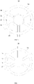
- FIG. 1 is a structural schematic diagram of an embodiment of a stator provided by the present application.
- the stator 100 roughly includes a stator core 10, a first phase winding 20, a second phase winding 22, and a third phase winding 24.
- stator core 10 Next, a structure of the stator core 10 is first introduced, and then a winding method of the first phase winding 20, the second phase winding 22, and the third phase winding 24 around the stator core 10 is explained.
- the stator core 10 includes a plurality of inner stator teeth 12 and a ring-shaped stator yoke 14.
- the plurality of inner stator teeth 12 are arranged on an inner side of the stator yoke 14 at intervals along a circumferential direction of the stator yoke 14 and extends to a central axis of the stator yoke 14, and a stator slot 13 is formed between adjacent inner stator teeth 12.
- the stator core 10 includes six inner stator teeth 12.
- the six inner stator teeth 12 are evenly distributed on the inner side of the stator yoke 14.
- Six stator slots 13 are formed between the six inner stator teeth 12.
- the stator yoke 14 is an integral structure, and the stator yoke 14 may be in a circular ring shape or a regular polygonal ring shape.
- the stator yoke 14 includes a plurality of sub-stator yokes 140 spliced together in sequence.
- Each of the sub-stator yokes 140 is provided with at least one inner stator tooth 12.
- the plurality of sub-stator yokes 140 are spliced together in sequence and enclosed to define a ring shape to form the stator core 10.
- the stator yoke 14 includes three sub-stator yokes 140.
- Each of the sub-stator yoke 140 is provided with two inner stator teeth 12.
- the three sub-stator yokes 140 are spliced together and enclosed to form the stator core 10.
- the sub-stator yokes 140 are independent with each other and can be manufactured. Therefore, smaller-sized materials can also be used to manufacture the sub-stator yoke 140, which improves the material utilization rate for manufacturing the stator core s 10 and reduces the producing cost of the stator core 10.
- each of the sub-stator yokes 140 along the circumferential direction has a protrusion 141
- another end of each of the sub-stator yokes 140 along the circumferential direction has a groove 143. Adjacent sub-stator yokes 140 are engaged and connected by the protrusion 141 and the groove 143.
- the protrusion 141 is a half cylinder
- the groove 143 is a semi-circular groove
- the half cylinder is engaged with the semi-circular groove to connect two adjacent yokes 120.
- the protrusion 141 may also be triangular
- the groove 143 is correspondingly a triangular groove.
- shapes of the protrusion 141 and the groove 143 may be engaged and connected with each other, and the shapes of the protrusion 141 and the groove 143 is not limited in the present application.
- each of the stator cores 10 further includes pole shoes 15, and the pole shoes 15 are connected to free ends of the inner stator teeth 12 away from the stator yoke 14.
- a side of the pole shoe 15 facing the central axis of the stator yoke 140 is a circular arc surface, which is used to cooperate with a rotor.
- a circular arc surface which is used to cooperate with a rotor.
- a gap is defined between adjacent pole shoes 15, and an arc length of the pole shoe 15 along the circumferential direction is greater than a width of the inner stator tooth 12 along the circumferential direction, so that a larger and more uniform magnetic field is generated between the pole shoes 15 and the rotor to be beneficial to increase a power density of the stator 100.
- the pole shoe 15 and the inner stator tooth 12 are an integral structure, and the pole shoe 15 and the inner stator tooth 12 can be punched and formed at one time, or the pole shoe 15 can be welded to the inner stator tooth 12, that is, the pole shoe 15 and the inner stator tooth 12 are non-removable.
- each of the pole shoes 15 is detachably connected to a corresponding one of the inner stator teeth 12.
- an end of each of the inner stator teeth 12 away from the stator yokes 14 is provided with an insertion slot 120
- an end of each of the pole shoes 15 facing the inner stator teeth 12 is provided with an insertion tooth 150
- the insertion tooth 150 and the insertion slot 120 are fastened together.
- the insertion tooth 150 includes a transition section 152 and a clamping section 153, and the transition section 152 is connected between the clamping section 153 and the pole shoe 15.
- An angle between two adjacent side surfaces connected with each other of the transition section 152 and the pole shoe 15 is greater than or equal to 90 degrees
- an angle between two adjacent side surfaces connected with each other of the transition section 152 and the clamping section 153 is greater than or equal to 90 degrees, so as to avoid forming acute angles of connecting portions between the transition section 152 and the pole shoe 15 and between the transition section 152 and the clamping section 153.
- the acute angle is usually easy to form a stress concentration area, and the accuracy of cutting acute angle is not high for the punching process. Therefore, the manufacturing difficulty of the inner stator teeth 12, the pole shoes 15 and the inserting teeth 150 can be relatively reduced, and the yield of the inner stator teeth 12, the pole shoes 15 and the inserting teeth 150 can be improved.
- the transition section 152 is a rectangular body
- the clamping section 153 is a trapezoid-like body
- the trapezoid-like body is formed by truncating two acute corners of a trapezoid body.
- a contour shape of the insertion slot 120 matches a contour shape of the inserting tooth 150, so that angles between adjacent side surfaces of the insertion slot 120 are greater than or equal to 90 degrees, thereby avoiding a stress concentration area generating at the insertion slot 120 and reducing the manufacturing difficulty of the insertion slot 120.
- the inner stator tooth 12 is a straight teeth, that is, no pole shoe 15 is provided at the free end of the inner stator tooth 12 away from the stator yoke 14, thereby simplifying the manufacturing process of the stator core 10 and reducing the cost, and at the same time, reducing a winding difficulty for the stator core 10.
- the stator core 10 may further include a plurality of outer stator teeth 16.
- the plurality of outer stator teeth 16 are arranged on an outer side of the stator yoke 14 at intervals along the circumferential direction of the stator yoke 14 and extend along a direction away from the central axis of the stator yoke 14, and further a heat dissipation channel is formed between adjacent outer stator teeth 16.
- an outer side surface of the stator yoke 14, the outer stator teeth 16 and a supporting surface of an external part for the outer stator teeth 16 are jointly enclosed to form a heat dissipation channel. Cool air can take away heat of the stator 100 through the heat dissipation channel to cool the stator 100, so as to avoid performance of the stator 100 reducing from being overheated, and to be beneficial to the power increase of the motor.
- Positions of the outer stator teeth 16 can correspond to positions of the inner stator teeth 12 in one-to-one correspondence, and are at least partially aligned along the circumferential direction of the stator yoke 14.
- a width of the outer stator tooth 16 along the circumferential direction of the stator yoke 14 is greater than a width of the inner stator tooth 12 along the circumferential direction of the stator yoke 14, or the width of the outer stator tooth 16 along the circumferential direction of the stator yoke 14 is equal to the width of the inner stator teeth 12 along the circumferential direction of the stator yoke 14, the width of the outer stator tooth 16 along the circumferential direction of the stator yoke 14 is less than the width of the inner stator teeth 12 along the circumferential direction of the stator yoke 14.
- the number of the outer stator teeth 16 may be more or less than the number of the inner stator teeth 12.
- the outer stator teeth 16 are evenly distributed on an outside of the stator yoke 14, and the positions of the outer stator teeth 16 do not need to correspond to the positions of the inner stator teeth 12.
- each of the first phase winding 20, the second phase winding 22, and the third phase winding 24 penetrates through two stator slots 13 separated by one stator slot 13 in therebetween and are wound around two adjacent inner stator teeth 12.
- the first phase winding 20, the second phase winding 22 and the third phase winding 24 are sequentially staggered with one inner stator tooth 12 along the circumferential direction of the stator yoke 14.
- the number of the inner stator teeth 12 and the number of the stator slots 13 are six, and the six inner stator teeth 12 and the six stator slots 13 are numbered in sequence, and the six inner stator teeth 12 are named 1 tooth, 2 tooth, ..., and 6 tooth, and the six stator slots 13 are named 1 slot, 2 slot, ..., and 6 slot.
- one first phase winding 20 penetrates through the 1 slot and the 3 slot separated by the 2 slot, and is wound around the 1 tooth and the 2 tooth.
- One second phase winding 22 penetrates through the 2 slot and the 4 slot separated by the 3 slot, and is wound around the 2 tooth and the 3 tooth.
- One third phase winding 24 penetrates through the 3 slot and the 5 slot separated by the 4 slot, and is wound around the 3 tooth and the 4 tooth.
- Another first phase winding 20 penetrates through the 4 slot and the 6 slot separated by the 5 slot, and is wound around the 4 tooth and the 5 tooth.
- Another second phase winding 22 penetrates through the 5 slot and the 1 slot separated by the 6 slot, and is wound around the 5 tooth and the 6 tooth.
- Another third phase winding 24 penetrates through the 6 slot and the 2 slot separated by the 1 slot, and is wound around the 6 tooth and the 1 tooth.
- In-phase windings are connected in parallel or in series to form a one-phase winding, and the first phase winding 20, the second phase winding 22 and the third phase winding 24 are connected in parallel or in series to form a three-phase winding.
- the embodiment of the present application adopts a winding method with a span of 2 slots, compared with a winding method with a span of 1 slot, the winding coefficient can be greatly improved, thereby increasing the output torque and the output power of the motor including the stator 100; and the first phase winding 20, the second phase winding 22 and the third phase winding 24 are limited to are sequentially staggered with one inner stator tooth 12 along the circumferential direction of the stator yoke 14, so that each phase winding is sequentially filled with the stator slots 13, which is beneficial improve the power density and the performance of the stator 100.
- the winding coefficient of a 6-slot 2-pole motor adopting a tooth-wound winding method with a span of 1 slot is 0.5
- the winding coefficient of a 6-slot 2-pole motor adopting a tooth-wound winding method with a span of 2 slots is increased to 0.866, thereby greatly improving the winding coefficient.
- the output torque and the output power of the motor with a span of 2 slots are relatively great.
- the stator slot 13 is further divided into a first side space 132 and a second side space 134 along the circumferential direction of the stator yoke 14.
- the first side space 132 and the second side space 134 of the same stator slot 13 are penetrated by two of the first phase winding 20, the second phase winding 22 and the third phase winding 24.
- the first side space 132 of the 2 slot is penetrated by the third phase winding 24.
- the second side space 134 of the 2 slot is penetrated by the second phase winding 22.
- the first phase winding 20 straddles the 2 slot and penetrates through the second side space 134 of the 1 slot and the first side space 132 of the 3 slot, and is wound around the 1 tooth and the 2 tooth defining the 2 slot. Winding conditions of the remaining slots are similar to this, so we won't repeat them one by one.
- cross-sectional areas of the first side space 132 and the second side space 134 perpendicular to the central axis of the stator yoke 14 are the same, and the first side space 132 and the second side space 134 are filled with corresponding windings, so that each winding generates a uniform electric field at the stator core 10, it is beneficial to improve the power density and the performance of the stator 100.
- the number of the inner stator teeth 12 and the number of the stator slots 13 are six.
- the number of the first phase winding 20, the number of the second phase winding 22 and the number of the third phase winding 24 are two.
- the two first phase windings 20, the two second phase windings 22 and the two third phase windings 24 are 180 degrees rotationally symmetric with a rotation center defined by the center axis of the stator yoke 14, and the current directions are opposite to each other, thereby ensuring that electrical angle of the mirror-symmetric in-phase windings is 0 degree, and ensuring that a distributed winding coefficient of this winding structure is 1.
- one first phase winding 20 penetrates through the 1 slot and the 3 slot, and its current flows from the 1 slot to the 3 slot; another first phase winding 20 penetrates through the 4 slot and the 6 slot, and its current flows from the 6 slot to the 4 slot.
- each of the first phase winding 20, the second phase winding 22, and the third phase winding 24 penetrates through two stator slots 13 separated by one stator slot 13 in therebetween and are wound around two adjacent inner stator teeth 12.
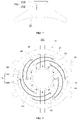
- the stator slot 13 is divided into an inner space 131 and an outer space 133 along a radial direction of the stator yoke 14.
- Each of the first phase winding 20, the second phase winding 22, and the third phase winding 24 penetrates through from the outer space 133 of one stator slot 13 of the two stator slots 13 to the inner space 131 of another stator slot 13.
- the first phase winding 20 penetrates through from the outer space 133 of the 1 slot to the inner space 131 of the 3 slot, and straddles the 2 slot to be wound around the 1 tooth and the 2 tooth.
- the second phase winding 22 penetrates through from the outer space 133 of the 2 slot to the inner space 131 of the 4 slot, and straddles the 3 slot to be wound around the 2 tooth and the 3 tooth.
- the third phase winding 24 penetrates through from the outer space 133 of the 3 slot to the inner space 131 of the 5 slot, and straddles the 4 slot to be wound around the 3 tooth and the 4 tooth.
- the stator with a span of 2 slots can increase the winding coefficient.
- the stator slot 13 is further divided into the inner space 131 and the outer space 133 along the radial direction of the stator yoke 14, each phase winding is wound around from the outer space 133 of one stator slot 13 to the inner space 131 of another stator slot 13, so that a double-layer winding in the radial direction can reduce the overlapping area of the end of each phase winding, thereby reducing an axial length of the stator 100 along the central axis of the stator yoke 14, and the volume of the stator 100 can be reduced and the power density can be increased.
- Cross-sectional areas of the inner space 131 and the outer space 133 perpendicular to the central axis of the stator yoke 14 are the same, and the inner space 131 and the outer space 133 are filled with windings, so that each winding generates a uniform electric field at the stator core 10, it is beneficial to improve the power density and the performance of the stator 100.
- the first phase winding 20, the second phase winding 22 and the third phase winding 24 are sequentially staggered with one inner stator tooth 12 along the circumferential direction of the stator yoke 14, so that the stator slots 13 are filled with phase windings, it is beneficial to improve the power density and the performance of the stator 100.
- each of the first phase winding 20, the second phase winding 22, and the third phase winding 24 penetrates through two stator slots 13 separated by one stator slot 13 in therebetween and are wound around two adjacent inner stator teeth 12.
- the stator slot 13 is divided into an inner space 131 and an outer space 133 along the radial direction of the stator yoke 14, and each of the first phase winding 20, the second phase winding 22, and the third phase winding 24 penetrates through inner spaces 131 of the corresponding two stator slots 13, or penetrates through outer space 133 of the corresponding two stator slots.
- the stator with a span of 2 slots can increase the winding coefficient.
- each of the first phase winding 20, the second phase winding 22, and the third phase winding 24 penetrates through inner spaces 131 of the corresponding two stator slots 13, or penetrates through outer spaces 133 of the corresponding two stator slots, so that the windings do not overlap each other, thereby reducing an axial length of the stator 100 along the central axis of the stator yoke 14, and the volume of the stator 100 can be reduced and the power density can be increased.
- One of the inner space 131 and the outer space 133 of each stator slot 13 is penetrated by the first phase winding 20, the second phase winding 22, or the third phase winding 24. Another is in an idle state without being penetrated by anyone of the first phase winding. 20, the second phase winding 22 and the third phase winding 24.
- one of the inner space 131 and the outer space 133 of each stator slot 13 is occupied by one or two of the first phase winding 20, the second phase winding 22, and the third phase winding 24.
- Vacant inner space 131 or vacant outer space 133 is configured as a heat dissipation channel to facilitate cooling the stator 100.
- the inner space 131 of the 3 slot is occupied by the second phase winding 22 (reference number 221) and the third phase winding 24 (reference number 241).
- the outer space 133 of the 3 slot is in an idle state without occupied by any winding.
- the first phase winding 20 (reference number 202) straddles the outer space 133 of the 3 slot and is wound around the 2 tooth and the 3 tooth.
- both of the inner space 131 and the outer space 133 of each stator slot 13 can be occupied by the first phase winding 20, the second phase winding 22, or the third phase winding 24.
- the first phase winding 20 includes a first phase inner winding 201 and a first phase outer winding 202.
- the second phase winding 22 includes a second phase inner winding 221 and a second phase outer winding 222.
- the third phase winding 24 includes a third phase inner winding 241 and a third phase outer winding 242.
- Each of the first phase inner winding 201, the second phase inner winding 221, and the third phase inner winding 241 is penetrated through inner spaces 131 of the corresponding two stator slots 13.
- Each of the first phase outer winding 202, the second phase outer winding 222, and the third phase outer winding 224 is penetrate through outer spaces 133 of the corresponding two stator slots 13.
- the first phase inner winding 201, the second phase inner winding 221 and the third phase inner winding 241 are sequentially staggered with two inner stator teeth 12 along the circumferential direction of the stator yoke 14.
- the first phase outer winding 202, the second phase outer winding 222 and the third phase outer winding 242 are sequentially staggered with two inner stator teeth 12 along the circumferential direction of the stator yoke 14.
- the first phase outer winding 202 penetrates through the outer spaces 133 of the 2 slot and the 4 slot.
- the second phase outer winding 222 penetrates through the out spaces 133 of the 4 slog and the 6 slot.
- the third phase outer winding 224 penetrates through the outer spaces 133 of the 6 slot and the 2 slot.
- the first phase inner winding 201 penetrates through the inner spaces 131 of the 5 slot and the 1 slot.
- the second phase inner winding 221 penetrates through the inner spaces 131 of the 1 slot and the 3 slot, and the third phase inner winding 241 penetrates through the inner spaces 131 of the 3 slot and the 5 slot.
- the inner space 131 is further divided into a first inner sub-space 131a and a second inner sub-space 131b along the circumferential direction of the stator yoke 14.
- Each of the first phase inner winding 201, the second phase inner winding 221 and the third phase inner winding 241 penetrates through a first inner sub-space 131a and a second inner sub-space 131b of the corresponding two stator slots 13 which are adjacent to the wound two inner stator teeth 12.
- the outer space 133 is further divided into a first outer sub-space 133a and a second outer sub-space 133b along the circumferential direction of the stator yoke 14.
- Each of the first phase outer winding 202, the second phase outer winding 222, and the third phase outer space winding 242 penetrates through a first outer sub-space 133a and a second outer sub-space 133b of the corresponding two stator slots 13 which are adjacent to the wound two inner stator teeth 12.
- Cross-sectional areas of the inner space 131 and the outer space 133 perpendicular to the central axis of the stator yoke 14 are the same.
- Cross-sectional areas of the first inner sub-space 131a and the second inner sub-space 131b perpendicular to the central axis of the stator yoke 14 are the same.
- Cross-sectional areas of the first outer sub-space 133a and the second outer sub-space 133b perpendicular to the central axis of the stator yoke 14 are the same.
- the first inner sub-space 131a, the second inner sub-space 131b, the first outer sub-space 133a, and the second outer sub-space 133b penetrated by corresponding windings are full of windings, so that each winding generates a uniform electric field at the stator core 10, it is beneficial to improve the power density and the performance of the stator 100.
- each of the first phase outer winding 202, the second phase outer winding 222, and the third phase outer winding 242 has an exposed portion exposed from outer spaces of the corresponding two stator slots 13, which includes two radial portions 203 and a circumferential portion 204.
- Each of the radial portions 203 extends toward the stator yoke 14 along the radial direction of the stator yoke 14.
- the circumferential portion 204 extends along the circumferential direction of the stator yoke 14, and the circumferential portion 204 is connected to the two radial portions 203.
- the outer space 133 of the stator slot 13 sandwiched between the two radial portions 203 is idle and is configured as a heat dissipation channel.
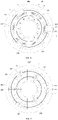
- the outer spaces 133 of the stator slots 13 sandwiched between the two radial portions 203 of the first phase outer winding 202, the second phase outer winding 222, and the third phase outer winding 242 are idle and configured as heat dissipation channels 135.
- Cold air penetrates through the heat dissipation channels 135 to remove heat from the stator 100 to cool the stator 100, so as to avoid the performance of the stator 100 reducing from being overheated, and to be beneficial to the power increase of the motor.
- a gap is defined between the first phase inner winding 201 and the second phase outer winding 222 and the third phase outer winding 242 along the radial direction of the stator yoke 14, and the gaps are configured as heat dissipation channels 135.
- the inner space 131 of the 6 slot is not penetrated by any winding, while the outer space 133 of the 6 slot is penetrated by the second phase outer winding 222 and the third phase outer winding 242, and the first phase inner winding 201 straddles the inner space 131 of the 6 slot. Therefore, the gaps are defined between the first phase inner winding 201 and the second phase outer winding 222 and the third phase outer winding 242 along the radial direction of the stator yoke 14, so that cold air can penetrate through the inner space 131 from the gap to take away heat from the stator 100, thereby cooling the stator 100.
- a gap is defined between the second phase inner winding 221 and the first phase outer winding 202 and the third phase outer winding 242 along the radial direction of the stator yoke 14, and the gap is configured as a heat dissipation channel 135.
- a gap is defined between the third phase inner winding 241 and the first phase outer winding 202 and the second phase outer winding 222 along the radial direction of the stator yoke 14, and the gap is configured as a heat dissipation channel 135.
- a gap is defined between the first phase outer winding 202 and the second phase inner winding 221 and the third phase inner winding 241 along the radial direction of the stator yoke 14, and the gap is configured as a heat dissipation channel 135.
- a gap is defined between the second phase outer winding 222 and the first phase inner winding 201 and the third phase inner winding 241 along the radial direction of the stator yoke 14, and the gap is configured as a heat dissipation channel 135.
- a gap is defined between the third phase outer winding 242 and the first phase inner winding 201 and the second phase inner winding 221 along the radial direction of the stator yoke 14, and the gap is configured as a heat dissipation channel 135.
- two of the first phase winding 20, the second phase winding 22, and the third phase winding 24 penetrate through the same inner space 131 or the same outer space 133, there is a gap between the two windings along the circumferential direction of the stator yoke 14, and the gap is configured as a heat dissipation channel 135.
- a gap is defined between the first phase inner winding 201 and the second phase inner winding 221 penetrating through the same inner space 131 along the circumferential direction of the stator yoke 14
- a gap is defined between the second phase inner winding 221 and the third phase inner winding 241 penetrating through the same inner space 131 along the circumferential direction of the stator yoke 14
- a gap is defined between the third phase inner winding 241 and the first phase inner winding 201 penetrating through the same inner space 131 along the circumferential direction of the stator yoke 14
- a gap is defined between the first phase outer winding 202 and the second phase outer winding 222 penetrating through the same outer space 133 along the circumferential direction of the stator yoke 14
- a gap is defined between the second phase outer winding 222 and the third phase outer winding 242 penetrating through the same outer space 133 along the circumferential direction of the stator yoke
- each of the first phase winding 20, the second phase winding 22, and the third phase winding 24 penetrating through the outer spaces 133 is routed on the stator yoke 14 to expose at least a part of the outer spaces which is correspondingly straddled thereby.
- the at least a part of the outer spaces 133 is configured as a heat dissipation channel 135.
- each of the first phase outer winding 202, the second phase outer winding 222, and the third phase outer winding 242 is routed on a corresponding part of the stator yoke 14 to avoid the correspondingly straddled outer space 133, thereby further exposing at least a part of the straddled outer space 133.
- the straddled outer space 133 is in an idle state, and the straddled outer space 133 is configured as a heat dissipation channel 135.
- the stator core 10 further includes a plurality of outer stator teeth 16, the plurality of outer stator teeth 16 are arranged on the outer side of the stator yoke 14 at intervals along the circumferential direction of the stator yoke 14, and extends away from the central axis of the stator yoke 14, so a heat dissipation channel 135 is defined between adjacent outer stator teeth 16.
- each of the first phase winding 20, the second phase winding 22, and the third phase winding 24 penetrating through the outer space 133 is routed in a range defined from the inner side of the stator yoke 14 to the outer side of the outer stator teeth 16 away from the central axis of the stator yoke 14 to expose corresponding straddled outer space 133.
- the straddled outer space 133 is in an idle state, and the straddled outer space 133 is configured as a heat dissipation channel 135.
- each of the first phase outer winding 202, the second phase outer winding 222, and the third phase outer winding 242 can be routed on the stator yoke 14 and the outer stator teeth 16 and in a range defined from the stator yoke 14 or the inner side of the stator 14 to the outer stator teeth 16 away from the central axis of the stator yoke 14 to expose corresponding straddled outer space 133.
- the straddled outer space 133 is in an idle state, and a space defined between adjacent outer stator teeth 16 is not completely blocked by wires of each phase winding. Therefore, vacant outer space 133 and portions between adjacent outer stator teeth 16 not covered by windings may be configured as heat dissipation channels 135.
- the stator yoke 14 includes a plurality of sub-stator yokes 140 spliced together in sequence.
- Each sub-stator yoke 140 is provided with at least two inner stator teeth 12.
- the two inner stator teeth 12 wound by the first phase outer winding 202, the second phase outer winding 222 and the third phase outer winding 242 are located on the same sub-stator yoke 140.
- the two inner stator teeth 12 wound by the first phase inner winding 201, the second phase inner winding 221 and the third phase inner winding 241 are located on two adjacent sub-stator yokes 140.
- the first phase outer winding 202, the second phase outer winding 222, or the third phase outer winding 242 can be wound first, and then the plurality of sub-stator yokes 140 are spliced with each other to form the stator core 10, after the splicing is completed, each of the first phase inner winding 201, the second phase inner winding 221, and the third phase inner winding 241 is wound, so that the difficulty of winding the first phase outer winding 202, the second phase outer winding 222 and the first phase can be reduced to easily assemble the winding structure of windings on the stator 10, to facilitate mechanized winding, thereby improving the production efficiency of the stator 100.
- the present application also provides a motor 300.
- the motor 300 includes a rotor 200 and a stator 100 mentioned as the above, and the rotor 200 is provided in the stator 100.
- the present application discloses a stator and a motor.
- the stator provided in this application adopts a winding method with a span of 2 slots, compared with a winding method with a span of 1 slot, the stator with a span of 2 slots can greatly increase the winding coefficient, thereby improving the output torque and the output power of the motor including the stator, and each of the first phase winding, the second phase winding, and the third phase winding penetrates through inner spaces of the corresponding two stator slots, or penetrates through outer spaces of the corresponding two stator slots, so that the windings do not overlap each other, thereby reducing an axial length of the stator along the central axis of the stator yoke, the volume of the stator can be reduced and the power density can be increased, and further the output torque and the output power of the motor including the stator are improved.
Landscapes
- Engineering & Computer Science (AREA)
- Power Engineering (AREA)
- Iron Core Of Rotating Electric Machines (AREA)
- Windings For Motors And Generators (AREA)
Abstract
Description
- This application claims priorities of four Chinese Patent Application No.
CN201911422872.6 CN201922500766.7 CN201922499845.0 CN201922501602.6 - This application relates to the field of motor technology, in particular to a stator and a motor.
- Low-power high-speed motor in the fields of automobiles, home appliances, medical equipment, and robots is becoming more and more extensive, and the requirements for power density are getting higher and higher. This requires motors not only to have a higher output power, but also to have a small overall volume. At the same rotating speed, the power increase mainly depends on the torque increase, and a winding structure with a larger winding coefficient is a key factor. On the other hand, the increase of power density is also related to the overall volume of the motor, and reducing a diameter of the stator or shortening an axial length are both key factors. In addition, compared with ordinary motors, the high-speed motor has poor heat dissipation performance due to its high speed, which further limits the power increase of the high-speed motor.
- This application mainly provides a stator and a motor to solve the problem that the output torque and the output power of the motor are not high.
- In order to solve the above technical problems, a technical solution adopted in the present application is to provide a stator. The stator includes a stator core including a plurality of inner stator teeth and a ring-shaped stator yoke, characterized in that the plurality of inner stator teeth are arranged on an inner side of the stator yoke at intervals along a circumferential direction of the stator yoke, and extend to a central axis of the stator yoke, to form stator slots between adjacent inner stator teeth; and a first phase winding, a second phase winding and a third phase winding, each penetrating through two stator slots which are separated by one stator slot in therebetween, and wound around two adjacent inner stator teeth; characterized in that each of the stator slots is divided into an inner space and an outer space along a radial direction of the stator yoke, each of the first phase winding, the second phase winding and the third phase winding penetrates through inner spaces of the corresponding two stator slots, or penetrates through outer spaces of the corresponding two stator slots.
- In some embodiments, one of the inner space and the outer space of each of the stator slots is penetrated by the first phase winding, the second phase winding, or the third phase winding, and another thereof is in an idle state without being penetrated by any one of the first phase winding, the second phase winding, and the third phase winding.
- In some embodiments, the first phase winding includes a first phase inner winding and a first phase outer winding, the second phase winding includes a second phase inner winding and a second phase outer winding, the third phase winding includes a third phase inner winding and a third phase outer winding, characterized in that each of the first phase inner winding, the second phase inner winding and the third phase inner winding penetrates through inner spaces of the corresponding two stator slots, and each of the first phase outer winding, the second phase outer winding and the third phase outer winding penetrates through outer spaces of the corresponding two stator slots.
- In some embodiments, the first phase inner winding, the second phase inner winding and the third phase inner winding are sequentially staggered with two inner stator teeth along the circumferential direction of the stator yoke; the first phase outer winding, the second phase outer winding and the third phase outer winding are sequentially staggered with two inner stator teeth along the circumferential direction of the stator yoke.
- In some embodiments, each of the inner spaces is divided into a first inner sub-space and a second inner sub-space along the circumferential direction of the stator yoke, and each of the first phase inner winding, the second phase inner winding and the third phase inner winding penetrates through a first inner sub-space and a second inner sub-space of the corresponding two stator slots which are adjacent to the wound two inner stator teeth; and each of the outer spaces is divided into a first outer sub-space and a second outer sub-space along the circumferential direction of the stator yoke, each of the first phase outer winding, the second phase outer winding and the third phase outer winding penetrates through a first outer sub-space and a second outer sub-space of the corresponding two stator slots which are adjacent to the wound two inner stator teeth.
- In some embodiments, the stator yoke includes a plurality of sub-stator yokes spliced together in sequence, each of the sub-stator yokes is provided with at least two inner stator teeth, two inner stator teeth wound by each of the first phase outer winding, the second phase outer winding and the third phase outer winding are located on the same sub-stator yoke, two inner stator teeth wound by each of the first phase inner winding, the second phase inner winding and the third phase inner winding are located on two adjacent sub-stator yokes.
- In some embodiments, a gap is defined between the first phase inner winding and the second phase outer winding and the third phase outer winding along the radial direction of the stator yoke, a gap is defined between the second phase inner winding and the first phase outer winding and the third phase outer winding along the radial direction of the stator yoke, and a gap is defined between the third phase inner winding and the first phase outer winding and the second phase outer winding along the radial direction of the stator yoke.
- In some embodiments, two of the first phase winding, the second phase winding, and the third phase winding penetrate through the same inner space or the same outer space, and a gap is defined between two windings along the circumferential direction of the stator yoke.
- In some embodiments, each of the first phase winding, the second phase winding, and the third phase winding has an exposed portion exposed from outer spaces of the corresponding two stator slots, which includes two radial portions and a circumferential portion, characterized in that each of the radial portions extends toward the stator yoke along the radial direction of the stator yoke, the circumferential portion extends along the circumferential direction of the stator yoke and is connected to the two radial portions.
- In some embodiments, the stator core further includes a plurality of outer stator teeth, and the plurality of outer stator teeth are arranged on an outer side of the stator yoke at intervals.
- In some embodiments, each of the first phase winding, the second phase winding, and the third phase winding penetrating through the outer spaces is routed on the stator yoke to expose at least a part of the outer spaces which is correspondingly straddled thereby, and the at least a part of the outer spaces is configured as a heat dissipation channel.
- In some embodiments, each of the first phase winding, the second phase winding, and the third phase winding penetrating through the outer spaces is routed in a range defined from the inner side of the stator yoke to the outer side of the outer stator teeth away from the central axis of the stator yoke to expose at least a part of the outer spaces which is correspondingly straddled thereby, and the at least a part of the outer spaces is configured as a heat dissipation channel.
- In some embodiments, the stator core further includes pole shoes, and the pole shoes are connected to free ends of the inner stator teeth away from the stator yoke.
- In some embodiments, each of the pole shoes and a corresponding one of the inner stator teeth are an integral structure, or each of the pole shoes is detachably connected to a corresponding one of the inner stator teeth.
- In some embodiments, an end of each of the inner stator teeth away from the stator yoke is provided with an insertion slot, an end of each of the pole shoes facing a corresponding one of the inner stator teeth is provided with an insertion tooth, and the insertion tooth and the insertion slot are fastened together.
- In some embodiments, the number of the inner stator teeth and the number of the stator slots are six, the number of the first phase winding, the number of the second phase winding and the number of the third phase winding are two, and the two first phase windings, the two second phase windings and the two third phase windings are 180 degrees rotationally symmetric with a rotation center defined by the center axis of the stator yoke, and current directions are opposite to each other.
- In order to solve the above technical problems, another technical solution adopted in the application is to provide a motor. The motor includes a rotor and a stator as described above, and the rotor is arranged in the stator.
- The beneficial effect of the present application is: different from the prior art, the present application discloses a stator and a motor. The stator provided in this application adopts a winding method with a span of 2 slots, compared with a winding method with a span of 1 slot, the stator with a span of 2 slots can greatly increase the winding coefficient, thereby improving the output torque and the output power of the motor including the stator, and each of the first phase winding, the second phase winding, and the third phase winding penetrates through inner spaces of the corresponding two stator slots, or penetrates through outer spaces of the corresponding two stator slots, so that the windings do not overlap each other, thereby reducing an axial length of the stator along the central axis of the stator yoke, the volume of the stator can be reduced and the power density can be increased, and further the output torque and the output power of the motor including the stator are improved.
- In order to make the technical solution described in the embodiments of the present disclosure clearer, the drawings used for the description of the embodiments will be briefly described. Apparently, the drawings described below are only for illustration but not for limitation. It should be understood that, one skilled in the art might acquire other drawings based on these drawings, without paying any creative efforts.
-
FIG. 1 is a structural schematic diagram of a first embodiment of a stator provided by the present application. -
FIG. 2 is a structural schematic diagram of a first embodiment of a stator core of the stator inFIG. 1 . -
FIG. 3 is a structural schematic diagram of a second embodiment of the stator core of the stator inFIG. 1 . -
FIG. 4 is a structural schematic diagram of a third embodiment of the stator core of the stator inFIG. 1 . -
FIG. 5 is a structural schematic diagram of a fourth embodiment of the stator core of the stator inFIG. 1 . -
FIG. 6 is a structural schematic diagram of a sub-stator yoke and inner stator teeth of the stator core inFIG. 5 . -
FIG. 7 is a structural schematic diagram of a pole shoe of the stator core inFIG. 3 orFIG. 5 . -
FIG. 8 is a structural schematic diagram of a second embodiment of the stator provided by the present application. -
Fig. 9 is a structural schematic diagram of a third embodiment of the stator provided by the present application. -
Fig. 10 is a structural schematic diagram of a fourth embodiment of the stator provided by the present application. -
Fig. 11 is a structural schematic diagram of a five embodiment of the stator provided by the present application. -
FIG. 12 is a structural schematic diagram of a sixth embodiment of the stator provided by the present application. -
FIG. 13 is a structural schematic diagram of a seventh embodiment of the stator provided by the present application. -
FIG. 14 is a structural schematic diagram of an eighth embodiment of the stator provided by the present application. -
FIG. 15 a structural schematic diagram of a ninth embodiment of the stator provided by the present application. -
FIG. 16 is a structural schematic diagram of one embodiment of a motor provided by the present application. - The technical solutions in the embodiments of the present application will be clearly and completely described below in conjunction with the drawings in the embodiments of the present application. Obviously, the described embodiments are only a part of the embodiments of the present application, rather than all the embodiments. Based on the embodiments in this application, all other embodiments obtained by those of ordinary skill in the art without creative work shall fall within the protection scope of this application.
- The terms "first", "second", and "third" in the embodiments of the present application are only used for descriptive purposes, and cannot be understood as indicating or implying relative importance or implicitly indicating the number of indicated technical features. Thus, the features defined with "first", "second", and "third" may explicitly or implicitly include at least one of the features. In the description of the present application, "a plurality of' means at least two, such as two, three, etc., unless specifically defined otherwise. In addition, the terms "including" and "having" and any variations thereof are intended to cover non-exclusive inclusions. For example, a process, method, system, product, or device that includes a series of steps or units is not limited to the listed steps or units, but optionally includes unlisted steps or units, or optionally also includes other steps or units inherent to these processes, methods, products or equipment.
- Mentioning "embodiments" herein means that a specific feature, structure, or characteristic described in conjunction with the embodiments may be included in at least one embodiment of the present application. The appearance of the phrase in various places in the specification does not necessarily Referring to the same embodiment, nor is it an independent or alternative embodiment mutually exclusive with other embodiments. Those skilled in the art clearly and implicitly understand that the embodiments described herein can be combined with other embodiments.
- The present application provides a
stator 100. Referring toFIG. 1, FIG. 1 is a structural schematic diagram of an embodiment of a stator provided by the present application. - The
stator 100 roughly includes astator core 10, a first phase winding 20, a second phase winding 22, and a third phase winding 24. - Next, a structure of the
stator core 10 is first introduced, and then a winding method of the first phase winding 20, the second phase winding 22, and the third phase winding 24 around thestator core 10 is explained. - Referring to
FIG. 2 , thestator core 10 includes a plurality ofinner stator teeth 12 and a ring-shapedstator yoke 14. The plurality ofinner stator teeth 12 are arranged on an inner side of thestator yoke 14 at intervals along a circumferential direction of thestator yoke 14 and extends to a central axis of thestator yoke 14, and astator slot 13 is formed between adjacentinner stator teeth 12. - For example, the
stator core 10 includes sixinner stator teeth 12. The sixinner stator teeth 12 are evenly distributed on the inner side of thestator yoke 14. Sixstator slots 13 are formed between the sixinner stator teeth 12. - In some embodiments, as shown in
FIG. 1 to FIG. 4 , thestator yoke 14 is an integral structure, and thestator yoke 14 may be in a circular ring shape or a regular polygonal ring shape. - In other embodiments, as shown in
FIG. 5 , thestator yoke 14 includes a plurality ofsub-stator yokes 140 spliced together in sequence. Each of thesub-stator yokes 140 is provided with at least oneinner stator tooth 12. The plurality ofsub-stator yokes 140 are spliced together in sequence and enclosed to define a ring shape to form thestator core 10. - For example, the
stator yoke 14 includes threesub-stator yokes 140. Each of thesub-stator yoke 140 is provided with twoinner stator teeth 12. The threesub-stator yokes 140 are spliced together and enclosed to form thestator core 10. - When multiple
sub-stator yokes 140 are not combined into thestator core 10, thesub-stator yokes 140 are independent with each other and can be manufactured. Therefore, smaller-sized materials can also be used to manufacture thesub-stator yoke 140, which improves the material utilization rate for manufacturing the stator core s 10 and reduces the producing cost of thestator core 10. - Specifically, as shown in
FIG. 6 , one end of each of thesub-stator yokes 140 along the circumferential direction has aprotrusion 141, and another end of each of thesub-stator yokes 140 along the circumferential direction has agroove 143. Adjacentsub-stator yokes 140 are engaged and connected by theprotrusion 141 and thegroove 143. - For example, the
protrusion 141 is a half cylinder, thegroove 143 is a semi-circular groove, and the half cylinder is engaged with the semi-circular groove to connect twoadjacent yokes 120. Theprotrusion 141 may also be triangular, and thegroove 143 is correspondingly a triangular groove. - It is only necessary that shapes of the
protrusion 141 and thegroove 143 may be engaged and connected with each other, and the shapes of theprotrusion 141 and thegroove 143 is not limited in the present application. - In some embodiments, as shown in
FIG. 2 andFIG. 3 , each of thestator cores 10 further includes pole shoes 15, and the pole shoes 15 are connected to free ends of theinner stator teeth 12 away from thestator yoke 14. - A side of the
pole shoe 15 facing the central axis of thestator yoke 140 is a circular arc surface, which is used to cooperate with a rotor. When the rotor is located in a space defined by the plurality of the pole shoes 15, there is a gap defined between the circular arc surface and the rotor to facilitate the rotor rotating relative to thestator 100. - A gap is defined between
adjacent pole shoes 15, and an arc length of thepole shoe 15 along the circumferential direction is greater than a width of theinner stator tooth 12 along the circumferential direction, so that a larger and more uniform magnetic field is generated between the pole shoes 15 and the rotor to be beneficial to increase a power density of thestator 100. - Optionally, as shown in
FIG. 2 , thepole shoe 15 and theinner stator tooth 12 are an integral structure, and thepole shoe 15 and theinner stator tooth 12 can be punched and formed at one time, or thepole shoe 15 can be welded to theinner stator tooth 12, that is, thepole shoe 15 and theinner stator tooth 12 are non-removable. - Or, as shown in
FIG. 3 andFIG. 5 , each of the pole shoes 15 is detachably connected to a corresponding one of theinner stator teeth 12. - Referring to
FIG. 6 andFIG. 7 , an end of each of theinner stator teeth 12 away from the stator yokes 14 is provided with aninsertion slot 120, an end of each of the pole shoes 15 facing theinner stator teeth 12 is provided with aninsertion tooth 150, and theinsertion tooth 150 and theinsertion slot 120 are fastened together. - Specifically, the
insertion tooth 150 includes atransition section 152 and aclamping section 153, and thetransition section 152 is connected between the clampingsection 153 and thepole shoe 15. An angle between two adjacent side surfaces connected with each other of thetransition section 152 and thepole shoe 15 is greater than or equal to 90 degrees, an angle between two adjacent side surfaces connected with each other of thetransition section 152 and theclamping section 153 is greater than or equal to 90 degrees, so as to avoid forming acute angles of connecting portions between thetransition section 152 and thepole shoe 15 and between thetransition section 152 and theclamping section 153. The acute angle is usually easy to form a stress concentration area, and the accuracy of cutting acute angle is not high for the punching process. Therefore, the manufacturing difficulty of theinner stator teeth 12, the pole shoes 15 and the insertingteeth 150 can be relatively reduced, and the yield of theinner stator teeth 12, the pole shoes 15 and the insertingteeth 150 can be improved. - For example, the
transition section 152 is a rectangular body, theclamping section 153 is a trapezoid-like body, and the trapezoid-like body is formed by truncating two acute corners of a trapezoid body. A contour shape of theinsertion slot 120 matches a contour shape of the insertingtooth 150, so that angles between adjacent side surfaces of theinsertion slot 120 are greater than or equal to 90 degrees, thereby avoiding a stress concentration area generating at theinsertion slot 120 and reducing the manufacturing difficulty of theinsertion slot 120. - In some embodiments, as shown in
FIG. 4 , theinner stator tooth 12 is a straight teeth, that is, nopole shoe 15 is provided at the free end of theinner stator tooth 12 away from thestator yoke 14, thereby simplifying the manufacturing process of thestator core 10 and reducing the cost, and at the same time, reducing a winding difficulty for thestator core 10. - In some embodiments, as shown in
FIG. 2 to FIG. 5 , thestator core 10 may further include a plurality ofouter stator teeth 16. The plurality ofouter stator teeth 16 are arranged on an outer side of thestator yoke 14 at intervals along the circumferential direction of thestator yoke 14 and extend along a direction away from the central axis of thestator yoke 14, and further a heat dissipation channel is formed between adjacentouter stator teeth 16. - That is, an outer side surface of the
stator yoke 14, theouter stator teeth 16 and a supporting surface of an external part for theouter stator teeth 16 are jointly enclosed to form a heat dissipation channel. Cool air can take away heat of thestator 100 through the heat dissipation channel to cool thestator 100, so as to avoid performance of thestator 100 reducing from being overheated, and to be beneficial to the power increase of the motor. - Positions of the
outer stator teeth 16 can correspond to positions of theinner stator teeth 12 in one-to-one correspondence, and are at least partially aligned along the circumferential direction of thestator yoke 14. For example, a width of theouter stator tooth 16 along the circumferential direction of thestator yoke 14 is greater than a width of theinner stator tooth 12 along the circumferential direction of thestator yoke 14, or the width of theouter stator tooth 16 along the circumferential direction of thestator yoke 14 is equal to the width of theinner stator teeth 12 along the circumferential direction of thestator yoke 14, the width of theouter stator tooth 16 along the circumferential direction of thestator yoke 14 is less than the width of theinner stator teeth 12 along the circumferential direction of thestator yoke 14. - Optionally, the number of the
outer stator teeth 16 may be more or less than the number of theinner stator teeth 12. Theouter stator teeth 16 are evenly distributed on an outside of thestator yoke 14, and the positions of theouter stator teeth 16 do not need to correspond to the positions of theinner stator teeth 12. - Next, the winding method of the first phase winding 20, the second phase winding 22, and the third phase winding 24 around the
stator core 10 will be explained. - As a whole, as shown in
FIG. 1 , each of the first phase winding 20, the second phase winding 22, and the third phase winding 24 penetrates through twostator slots 13 separated by onestator slot 13 in therebetween and are wound around two adjacentinner stator teeth 12. The first phase winding 20, the second phase winding 22 and the third phase winding 24 are sequentially staggered with oneinner stator tooth 12 along the circumferential direction of thestator yoke 14. - For example, the number of the
inner stator teeth 12 and the number of thestator slots 13 are six, and the sixinner stator teeth 12 and the sixstator slots 13 are numbered in sequence, and the sixinner stator teeth 12 are named 1 tooth, 2 tooth, ..., and 6 tooth, and the sixstator slots 13 are named 1 slot, 2 slot, ..., and 6 slot. - For example, one first phase winding 20 penetrates through the 1 slot and the 3 slot separated by the 2 slot, and is wound around the 1 tooth and the 2 tooth. One second phase winding 22 penetrates through the 2 slot and the 4 slot separated by the 3 slot, and is wound around the 2 tooth and the 3 tooth. One third phase winding 24 penetrates through the 3 slot and the 5 slot separated by the 4 slot, and is wound around the 3 tooth and the 4 tooth. Another first phase winding 20 penetrates through the 4 slot and the 6 slot separated by the 5 slot, and is wound around the 4 tooth and the 5 tooth. Another second phase winding 22 penetrates through the 5 slot and the 1 slot separated by the 6 slot, and is wound around the 5 tooth and the 6 tooth. Another third phase winding 24 penetrates through the 6 slot and the 2 slot separated by the 1 slot, and is wound around the 6 tooth and the 1 tooth.
- In-phase windings are connected in parallel or in series to form a one-phase winding, and the first phase winding 20, the second phase winding 22 and the third phase winding 24 are connected in parallel or in series to form a three-phase winding.
- The embodiment of the present application adopts a winding method with a span of 2 slots, compared with a winding method with a span of 1 slot, the winding coefficient can be greatly improved, thereby increasing the output torque and the output power of the motor including the
stator 100; and the first phase winding 20, the second phase winding 22 and the third phase winding 24 are limited to are sequentially staggered with oneinner stator tooth 12 along the circumferential direction of thestator yoke 14, so that each phase winding is sequentially filled with thestator slots 13, which is beneficial improve the power density and the performance of thestator 100. - For example, the winding coefficient of a 6-slot 2-pole motor adopting a tooth-wound winding method with a span of 1 slot is 0.5, while the winding coefficient of a 6-slot 2-pole motor adopting a tooth-wound winding method with a span of 2 slots is increased to 0.866, thereby greatly improving the winding coefficient. Under the same speed, the output torque and the output power of the motor with a span of 2 slots are relatively great.
- The
stator slot 13 is further divided into afirst side space 132 and asecond side space 134 along the circumferential direction of thestator yoke 14. Thefirst side space 132 and thesecond side space 134 of thesame stator slot 13 are penetrated by two of the first phase winding 20, the second phase winding 22 and the third phase winding 24. - As shown in
FIG. 1 , thefirst side space 132 of the 2 slot is penetrated by the third phase winding 24. Thesecond side space 134 of the 2 slot is penetrated by the second phase winding 22. The first phase winding 20 straddles the 2 slot and penetrates through thesecond side space 134 of the 1 slot and thefirst side space 132 of the 3 slot, and is wound around the 1 tooth and the 2 tooth defining the 2 slot. Winding conditions of the remaining slots are similar to this, so we won't repeat them one by one. - Further, cross-sectional areas of the
first side space 132 and thesecond side space 134 perpendicular to the central axis of thestator yoke 14 are the same, and thefirst side space 132 and thesecond side space 134 are filled with corresponding windings, so that each winding generates a uniform electric field at thestator core 10, it is beneficial to improve the power density and the performance of thestator 100. - The current directions of any two of the first phase winding 20, the second phase winding 22 and the third phase winding 24 in the
same stator slot 13 are opposite to each other. - As shown in
FIG. 1 , along the direction perpendicular to the central axis of thestator yoke 14, the current direction of the third phase winding 24 in thefirst side space 132 of the 2 slot is inflow, and the current direction of the second phase winding 22 in thesecond side space 134 of the 2 slot is outflow. - In this embodiment, the number of the
inner stator teeth 12 and the number of thestator slots 13 are six. The number of the first phase winding 20, the number of the second phase winding 22 and the number of the third phase winding 24 are two. The twofirst phase windings 20, the twosecond phase windings 22 and the twothird phase windings 24 are 180 degrees rotationally symmetric with a rotation center defined by the center axis of thestator yoke 14, and the current directions are opposite to each other, thereby ensuring that electrical angle of the mirror-symmetric in-phase windings is 0 degree, and ensuring that a distributed winding coefficient of this winding structure is 1. - As shown in
FIG. 1 , one first phase winding 20 penetrates through the 1 slot and the 3 slot, and its current flows from the 1 slot to the 3 slot; another first phase winding 20 penetrates through the 4 slot and the 6 slot, and its current flows from the 6 slot to the 4 slot. - Referring to
FIG. 8 , each of the first phase winding 20, the second phase winding 22, and the third phase winding 24 penetrates through twostator slots 13 separated by onestator slot 13 in therebetween and are wound around two adjacentinner stator teeth 12. - The
stator slot 13 is divided into aninner space 131 and anouter space 133 along a radial direction of thestator yoke 14. Each of the first phase winding 20, the second phase winding 22, and the third phase winding 24 penetrates through from theouter space 133 of onestator slot 13 of the twostator slots 13 to theinner space 131 of anotherstator slot 13. - As shown in
FIG. 8 , the first phase winding 20 penetrates through from theouter space 133 of the 1 slot to theinner space 131 of the 3 slot, and straddles the 2 slot to be wound around the 1 tooth and the 2 tooth. The second phase winding 22 penetrates through from theouter space 133 of the 2 slot to theinner space 131 of the 4 slot, and straddles the 3 slot to be wound around the 2 tooth and the 3 tooth. The third phase winding 24 penetrates through from theouter space 133 of the 3 slot to theinner space 131 of the 5 slot, and straddles the 4 slot to be wound around the 3 tooth and the 4 tooth. - Via the first phase winding 20, the second phase winding 22, and the third phase winding 24 are wound around two adjacent
inner stator teeth 12 with a span of 2 slots, compared with the stator with a span of 1 slot, the stator with a span of 2 slots provided by the present application can increase the winding coefficient. Under the same speed, the output torque and the output power of the motor with a span of 2 slots are greater; and thestator slot 13 is further divided into theinner space 131 and theouter space 133 along the radial direction of thestator yoke 14, each phase winding is wound around from theouter space 133 of onestator slot 13 to theinner space 131 of anotherstator slot 13, so that a double-layer winding in the radial direction can reduce the overlapping area of the end of each phase winding, thereby reducing an axial length of thestator 100 along the central axis of thestator yoke 14, and the volume of thestator 100 can be reduced and the power density can be increased. - Cross-sectional areas of the
inner space 131 and theouter space 133 perpendicular to the central axis of thestator yoke 14 are the same, and theinner space 131 and theouter space 133 are filled with windings, so that each winding generates a uniform electric field at thestator core 10, it is beneficial to improve the power density and the performance of thestator 100. - The first phase winding 20, the second phase winding 22 and the third phase winding 24 are sequentially staggered with one
inner stator tooth 12 along the circumferential direction of thestator yoke 14, so that thestator slots 13 are filled with phase windings, it is beneficial to improve the power density and the performance of thestator 100. - The current directions of any two of the first phase winding 20, the second phase winding 22, and the third phase winding 24 in the
same stator slot 13 are opposite to each other. - As shown in
FIG. 8 , along the direction perpendicular to the central axis of thestator yoke 14, the current direction of the third phase winding 24 in theinner space 131 of the 2 slot is inflow, and the current direction of the second phase winding 22 in theouter space 131 of the 2 slot is outflow. - Referring to
FIG. 9 , each of the first phase winding 20, the second phase winding 22, and the third phase winding 24 penetrates through twostator slots 13 separated by onestator slot 13 in therebetween and are wound around two adjacentinner stator teeth 12. - The
stator slot 13 is divided into aninner space 131 and anouter space 133 along the radial direction of thestator yoke 14, and each of the first phase winding 20, the second phase winding 22, and the third phase winding 24 penetrates throughinner spaces 131 of the corresponding twostator slots 13, or penetrates throughouter space 133 of the corresponding two stator slots. - As shown in
FIG. 9 , one first phase winding 20 (reference number 202) penetrates through theouter spaces 133 of the 2 slot and the 4 slot, and is wound around the 2 tooth and the 3 tooth; another first phase winding 20 (reference number 201) penetrates through theinner spaces 131 of the 5 slot and the 1 slot, and is wound around the 5 tooth and 6 tooth. - Via the first phase winding 20, the second phase winding 22, and the third phase winding 24 wound around two adjacent
inner stator teeth 12 with a span of 2 slots, compared with the stator with a span of 1 slot, the stator with a span of 2 slots provided by the present application can increase the winding coefficient. Under the same speed, the output torque and the output power of the motor with a span of 2 slots are greater; and each of the first phase winding 20, the second phase winding 22, and the third phase winding 24 penetrates throughinner spaces 131 of the corresponding twostator slots 13, or penetrates throughouter spaces 133 of the corresponding two stator slots, so that the windings do not overlap each other, thereby reducing an axial length of thestator 100 along the central axis of thestator yoke 14, and the volume of thestator 100 can be reduced and the power density can be increased. - One of the
inner space 131 and theouter space 133 of eachstator slot 13 is penetrated by the first phase winding 20, the second phase winding 22, or the third phase winding 24. Another is in an idle state without being penetrated by anyone of the first phase winding. 20, the second phase winding 22 and the third phase winding 24. In other words, one of theinner space 131 and theouter space 133 of eachstator slot 13 is occupied by one or two of the first phase winding 20, the second phase winding 22, and the third phase winding 24. Vacantinner space 131 or vacantouter space 133 is configured as a heat dissipation channel to facilitate cooling thestator 100. - As shown in
FIG. 9 , theinner space 131 of the 3 slot is occupied by the second phase winding 22 (reference number 221) and the third phase winding 24 (reference number 241). Theouter space 133 of the 3 slot is in an idle state without occupied by any winding. The first phase winding 20 (reference number 202) straddles theouter space 133 of the 3 slot and is wound around the 2 tooth and the 3 tooth. - In other embodiments, both of the
inner space 131 and theouter space 133 of eachstator slot 13 can be occupied by the first phase winding 20, the second phase winding 22, or the third phase winding 24. - Further, the first phase winding 20 includes a first phase inner winding 201 and a first phase outer winding 202. The second phase winding 22 includes a second phase inner winding 221 and a second phase outer winding 222. The third phase winding 24 includes a third phase inner winding 241 and a third phase outer winding 242. Each of the first phase inner winding 201, the second phase inner winding 221, and the third phase inner winding 241 is penetrated through
inner spaces 131 of the corresponding twostator slots 13. Each of the first phase outer winding 202, the second phase outer winding 222, and the third phase outer winding 224 is penetrate throughouter spaces 133 of the corresponding twostator slots 13. - The first phase inner winding 201, the second phase inner winding 221 and the third phase inner winding 241 are sequentially staggered with two
inner stator teeth 12 along the circumferential direction of thestator yoke 14. The first phase outer winding 202, the second phase outer winding 222 and the third phase outer winding 242 are sequentially staggered with twoinner stator teeth 12 along the circumferential direction of thestator yoke 14. - As shown in
FIG. 9 , the first phase outer winding 202 penetrates through theouter spaces 133 of the 2 slot and the 4 slot. The second phase outer winding 222 penetrates through theout spaces 133 of the 4 slog and the 6 slot. The third phase outer winding 224 penetrates through theouter spaces 133 of the 6 slot and the 2 slot. The first phase inner winding 201 penetrates through theinner spaces 131 of the 5 slot and the 1 slot. The second phase inner winding 221 penetrates through theinner spaces 131 of the 1 slot and the 3 slot, and the third phase inner winding 241 penetrates through theinner spaces 131 of the 3 slot and the 5 slot. - The
inner space 131 is further divided into a firstinner sub-space 131a and a secondinner sub-space 131b along the circumferential direction of thestator yoke 14. Each of the first phase inner winding 201, the second phase inner winding 221 and the third phase inner winding 241 penetrates through a firstinner sub-space 131a and a secondinner sub-space 131b of the corresponding twostator slots 13 which are adjacent to the wound twoinner stator teeth 12. - The
outer space 133 is further divided into a firstouter sub-space 133a and a secondouter sub-space 133b along the circumferential direction of thestator yoke 14. Each of the first phase outer winding 202, the second phase outer winding 222, and the third phase outer space winding 242 penetrates through a firstouter sub-space 133a and a secondouter sub-space 133b of the corresponding twostator slots 13 which are adjacent to the wound twoinner stator teeth 12. - Cross-sectional areas of the
inner space 131 and theouter space 133 perpendicular to the central axis of thestator yoke 14 are the same. Cross-sectional areas of the firstinner sub-space 131a and the secondinner sub-space 131b perpendicular to the central axis of thestator yoke 14 are the same. Cross-sectional areas of the firstouter sub-space 133a and the secondouter sub-space 133b perpendicular to the central axis of thestator yoke 14 are the same. The firstinner sub-space 131a, the secondinner sub-space 131b, the firstouter sub-space 133a, and the secondouter sub-space 133b penetrated by corresponding windings are full of windings, so that each winding generates a uniform electric field at thestator core 10, it is beneficial to improve the power density and the performance of thestator 100. - Referring to
FIG. 9 and FIG. 10 in combination, each of the first phase outer winding 202, the second phase outer winding 222, and the third phase outer winding 242 has an exposed portion exposed from outer spaces of the corresponding twostator slots 13, which includes tworadial portions 203 and acircumferential portion 204. Each of theradial portions 203 extends toward thestator yoke 14 along the radial direction of thestator yoke 14. Thecircumferential portion 204 extends along the circumferential direction of thestator yoke 14, and thecircumferential portion 204 is connected to the tworadial portions 203. Theouter space 133 of thestator slot 13 sandwiched between the tworadial portions 203 is idle and is configured as a heat dissipation channel. - In other words, the
outer spaces 133 of thestator slots 13 sandwiched between the tworadial portions 203 of the first phase outer winding 202, the second phase outer winding 222, and the third phase outer winding 242 are idle and configured asheat dissipation channels 135. Cold air penetrates through theheat dissipation channels 135 to remove heat from thestator 100 to cool thestator 100, so as to avoid the performance of thestator 100 reducing from being overheated, and to be beneficial to the power increase of the motor. - In other embodiments, as shown in
FIG. 11 , a gap is defined between the first phase inner winding 201 and the second phase outer winding 222 and the third phase outer winding 242 along the radial direction of thestator yoke 14, and the gaps are configured asheat dissipation channels 135. - As shown in
FIG. 9 , theinner space 131 of the 6 slot is not penetrated by any winding, while theouter space 133 of the 6 slot is penetrated by the second phase outer winding 222 and the third phase outer winding 242, and the first phase inner winding 201 straddles theinner space 131 of the 6 slot. Therefore, the gaps are defined between the first phase inner winding 201 and the second phase outer winding 222 and the third phase outer winding 242 along the radial direction of thestator yoke 14, so that cold air can penetrate through theinner space 131 from the gap to take away heat from thestator 100, thereby cooling thestator 100. - Correspondingly, a gap is defined between the second phase inner winding 221 and the first phase outer winding 202 and the third phase outer winding 242 along the radial direction of the
stator yoke 14, and the gap is configured as aheat dissipation channel 135. A gap is defined between the third phase inner winding 241 and the first phase outer winding 202 and the second phase outer winding 222 along the radial direction of thestator yoke 14, and the gap is configured as aheat dissipation channel 135. A gap is defined between the first phase outer winding 202 and the second phase inner winding 221 and the third phase inner winding 241 along the radial direction of thestator yoke 14, and the gap is configured as aheat dissipation channel 135. A gap is defined between the second phase outer winding 222 and the first phase inner winding 201 and the third phase inner winding 241 along the radial direction of thestator yoke 14, and the gap is configured as aheat dissipation channel 135. A gap is defined between the third phase outer winding 242 and the first phase inner winding 201 and the second phase inner winding 221 along the radial direction of thestator yoke 14, and the gap is configured as aheat dissipation channel 135. - Or, two of the first phase winding 20, the second phase winding 22, and the third phase winding 24 penetrate through the same
inner space 131 or the sameouter space 133, there is a gap between the two windings along the circumferential direction of thestator yoke 14, and the gap is configured as aheat dissipation channel 135. - Specifically, as shown in
FIG. 12 , a gap is defined between the first phase inner winding 201 and the second phase inner winding 221 penetrating through the sameinner space 131 along the circumferential direction of thestator yoke 14, a gap is defined between the second phase inner winding 221 and the third phase inner winding 241 penetrating through the sameinner space 131 along the circumferential direction of thestator yoke 14, a gap is defined between the third phase inner winding 241 and the first phase inner winding 201 penetrating through the sameinner space 131 along the circumferential direction of thestator yoke 14, a gap is defined between the first phase outer winding 202 and the second phase outer winding 222 penetrating through the sameouter space 133 along the circumferential direction of thestator yoke 14, a gap is defined between the second phase outer winding 222 and the third phase outer winding 242 penetrating through the sameouter space 133 along the circumferential direction of thestator yoke 14, a gap is defined between the third phase outer winding 242 and the first phase outer layer winding 202 penetrating through the sameouter space 133 along the circumferential direction of thestator yoke 14, and the gaps are configured asheat dissipation channels 135. - In some other embodiments, each of the first phase winding 20, the second phase winding 22, and the third phase winding 24 penetrating through the
outer spaces 133 is routed on thestator yoke 14 to expose at least a part of the outer spaces which is correspondingly straddled thereby. The at least a part of theouter spaces 133 is configured as aheat dissipation channel 135. - Specifically, as shown in
FIG. 13 , each of the first phase outer winding 202, the second phase outer winding 222, and the third phase outer winding 242 is routed on a corresponding part of thestator yoke 14 to avoid the correspondingly straddledouter space 133, thereby further exposing at least a part of the straddledouter space 133. The straddledouter space 133 is in an idle state, and the straddledouter space 133 is configured as aheat dissipation channel 135. - In other embodiments, as shown in
FIG. 14 , thestator core 10 further includes a plurality ofouter stator teeth 16, the plurality ofouter stator teeth 16 are arranged on the outer side of thestator yoke 14 at intervals along the circumferential direction of thestator yoke 14, and extends away from the central axis of thestator yoke 14, so aheat dissipation channel 135 is defined between adjacentouter stator teeth 16. - Further, each of the first phase winding 20, the second phase winding 22, and the third phase winding 24 penetrating through the
outer space 133 is routed in a range defined from the inner side of thestator yoke 14 to the outer side of theouter stator teeth 16 away from the central axis of thestator yoke 14 to expose corresponding straddledouter space 133. The straddledouter space 133 is in an idle state, and the straddledouter space 133 is configured as aheat dissipation channel 135. - Specifically, as shown in
FIG. 15 , each of the first phase outer winding 202, the second phase outer winding 222, and the third phase outer winding 242 can be routed on thestator yoke 14 and theouter stator teeth 16 and in a range defined from thestator yoke 14 or the inner side of thestator 14 to theouter stator teeth 16 away from the central axis of thestator yoke 14 to expose corresponding straddledouter space 133. The straddledouter space 133 is in an idle state, and a space defined between adjacentouter stator teeth 16 is not completely blocked by wires of each phase winding. Therefore, vacantouter space 133 and portions between adjacentouter stator teeth 16 not covered by windings may be configured asheat dissipation channels 135. - In some embodiments, referring to
FIG. 5 andFIG. 9 in combination, thestator yoke 14 includes a plurality ofsub-stator yokes 140 spliced together in sequence. Eachsub-stator yoke 140 is provided with at least twoinner stator teeth 12. The twoinner stator teeth 12 wound by the first phase outer winding 202, the second phase outer winding 222 and the third phase outer winding 242 are located on the samesub-stator yoke 140. The twoinner stator teeth 12 wound by the first phase inner winding 201, the second phase inner winding 221 and the third phase inner winding 241 are located on two adjacent sub-stator yokes 140. - Therefore, on one
sub-stator yoke 140, the first phase outer winding 202, the second phase outer winding 222, or the third phase outer winding 242 can be wound first, and then the plurality ofsub-stator yokes 140 are spliced with each other to form thestator core 10, after the splicing is completed, each of the first phase inner winding 201, the second phase inner winding 221, and the third phase inner winding 241 is wound, so that the difficulty of winding the first phase outer winding 202, the second phase outer winding 222 and the first phase can be reduced to easily assemble the winding structure of windings on thestator 10, to facilitate mechanized winding, thereby improving the production efficiency of thestator 100. - Based on this, the present application also provides a
motor 300. Referring toFIG. 16 , themotor 300 includes arotor 200 and astator 100 mentioned as the above, and therotor 200 is provided in thestator 100. - Different from the prior art, the present application discloses a stator and a motor. The stator provided in this application adopts a winding method with a span of 2 slots, compared with a winding method with a span of 1 slot, the stator with a span of 2 slots can greatly increase the winding coefficient, thereby improving the output torque and the output power of the motor including the stator, and each of the first phase winding, the second phase winding, and the third phase winding penetrates through inner spaces of the corresponding two stator slots, or penetrates through outer spaces of the corresponding two stator slots, so that the windings do not overlap each other, thereby reducing an axial length of the stator along the central axis of the stator yoke, the volume of the stator can be reduced and the power density can be increased, and further the output torque and the output power of the motor including the stator are improved.
- The above are only embodiments of the present disclosure and are not intended to limit the scope of the present disclosure. Any equivalent structural changes made under the concept of the present disclosure, using the contents of the specification of the present disclosure and the accompanying drawings, or applied directly/indirectly in other related fields of technology are included in the scope of protection of the present disclosure.
Claims (17)
- A stator, comprising:a stator core comprising a plurality of inner stator teeth and a ring-shaped stator yoke, characterized in that the plurality of inner stator teeth are arranged on an inner side of the stator yoke at intervals along a circumferential direction of the stator yoke, and extend to a central axis of the stator yoke, to form stator slots between adjacent inner stator teeth; anda first phase winding, a second phase winding and a third phase winding, each penetrating through two stator slots which are separated by one stator slot in therebetween, and wound around two adjacent inner stator teeth;characterized in that each of the stator slots is divided into an inner space and an outer space along a radial direction of the stator yoke, each of the first phase winding, the second phase winding and the third phase winding penetrates through inner spaces of the corresponding two stator slots, or penetrates through outer spaces of the corresponding two stator slots.
- The stator according to claim 1, characterized in that one of the inner space and the outer space of each of the stator slots is penetrated by the first phase winding, the second phase winding, or the third phase winding, and another thereof is in an idle state without being penetrated by any one of the first phase winding, the second phase winding, and the third phase winding.
- The stator according to claim 1, characterized in that the first phase winding comprises a first phase inner winding and a first phase outer winding, the second phase winding comprises a second phase inner winding and a second phase outer winding, the third phase winding comprises a third phase inner winding and a third phase outer winding, characterized in that each of the first phase inner winding, the second phase inner winding and the third phase inner winding penetrates through inner spaces of the corresponding two stator slots, and each of the first phase outer winding, the second phase outer winding and the third phase outer winding penetrates through outer spaces of the corresponding two stator slots.
- The stator according to claim 3, characterized in that the first phase inner winding, the second phase inner winding and the third phase inner winding are sequentially staggered with two inner stator teeth along the circumferential direction of the stator yoke; the first phase outer winding, the second phase outer winding and the third phase outer winding are sequentially staggered with two inner stator teeth along the circumferential direction of the stator yoke.
- The stator according to claim 3, characterized in that each of the inner spaces is divided into a first inner sub-space and a second inner sub-space along the circumferential direction of the stator yoke, and each of the first phase inner winding, the second phase inner winding and the third phase inner winding penetrates through a first inner sub-space and a second inner sub-space of the corresponding two stator slots which are adjacent to the wound two inner stator teeth; and
each of the outer spaces is divided into a first outer sub-space and a second outer sub-space along the circumferential direction of the stator yoke, each of the first phase outer winding, the second phase outer winding and the third phase outer winding penetrates through a first outer sub-space and a second outer sub-space of the corresponding two stator slots which are adjacent to the wound two inner stator teeth. - The stator according to claim 3, characterized in that the stator yoke comprises a plurality of sub-stator yokes spliced together in sequence, each of the sub-stator yokes is provided with at least two inner stator teeth, two inner stator teeth wound by each of the first phase outer winding, the second phase outer winding and the third phase outer winding are located on the same sub-stator yoke, two inner stator teeth wound by each of the first phase inner winding, the second phase inner winding and the third phase inner winding are located on two adjacent sub-stator yokes.
- The stator according to claim 3, characterized in that a gap is defined between the first phase inner winding and the second phase outer winding and the third phase outer winding along the radial direction of the stator yoke, a gap is defined between the second phase inner winding and the first phase outer winding and the third phase outer winding along the radial direction of the stator yoke, and a gap is defined between the third phase inner winding and the first phase outer winding and the second phase outer winding along the radial direction of the stator yoke.
- The stator according to claim 1, characterized in that two of the first phase winding, the second phase winding, and the third phase winding penetrate through the same inner space or the same outer space, and a gap is defined between two windings along the circumferential direction of the stator yoke.
- The stator according to claim 1, characterized in that each of the first phase winding, the second phase winding, and the third phase winding has an exposed portion exposed from outer spaces of the corresponding two stator slots, which comprises two radial portions and a circumferential portion, characterized in that each of the radial portions extends toward the stator yoke along the radial direction of the stator yoke, the circumferential portion extends along the circumferential direction of the stator yoke and is connected to the two radial portions.
- The stator according to claim 1, characterized in that the stator core further comprises a plurality of outer stator teeth, and the plurality of outer stator teeth are arranged on an outer side of the stator yoke at intervals.
- The stator according to claim 1 or 10, characterized in that each of the first phase winding, the second phase winding, and the third phase winding penetrating through the outer spaces is routed on the stator yoke to expose at least a part of the outer spaces which is correspondingly straddled thereby, and the at least a part of the outer spaces is configured as a heat dissipation channel.
- The stator according to claim 10, characterized in that each of the first phase winding, the second phase winding, and the third phase winding penetrating through the outer spaces is routed in a range defined from the inner side of the stator yoke to the outer side of the outer stator teeth away from the central axis of the stator yoke to expose at least a part of the outer spaces which is correspondingly straddled thereby, and the at least a part of the outer spaces is configured as a heat dissipation channel.
- The stator according to claim 1, characterized in that the stator core further comprises pole shoes, and the pole shoes are connected to free ends of the inner stator teeth away from the stator yoke.
- The stator according to claim 13, wherein each of the pole shoes and a corresponding one of the inner stator teeth are an integral structure, or each of the pole shoes is detachably connected to a corresponding one of the inner stator teeth.
- The stator according to claim 14, characterized in that an end of each of the inner stator teeth away from the stator yoke is provided with an insertion slot, an end of each of the pole shoes facing a corresponding one of the inner stator teeth is provided with an insertion tooth, and the insertion tooth and the insertion slot are fastened together.
- The stator according to claim 1, wherein the number of the inner stator teeth and the number of the stator slots are six, the number of the first phase winding, the number of the second phase winding and the number of the third phase winding are two, and the two first phase windings, the two second phase windings and the two third phase windings are 180 degrees rotationally symmetric with a rotation center defined by the center axis of the stator yoke, and current directions are opposite to each other.
- A motor, characterized in that the motor comprises a rotor and the stator according to any one of claims 1 to 16, and the rotor is arranged in the stator.
Applications Claiming Priority (5)
| Application Number | Priority Date | Filing Date | Title |
|---|---|---|---|
| CN201922501602.6U CN211670690U (en) | 2019-12-31 | 2019-12-31 | Stator and Motor |
| CN201922500766.7U CN211701635U (en) | 2019-12-31 | 2019-12-31 | Stator and Motor |
| CN201922499845.0U CN211629943U (en) | 2019-12-31 | 2019-12-31 | Stator and Motor |
| CN201911422872.6A CN113131633B (en) | 2019-12-31 | 2019-12-31 | Stator and motor |
| PCT/CN2020/137744 WO2021135994A1 (en) | 2019-12-31 | 2020-12-18 | Stator and motor |
Publications (2)
| Publication Number | Publication Date |
|---|---|
| EP3998693A1 true EP3998693A1 (en) | 2022-05-18 |
| EP3998693A4 EP3998693A4 (en) | 2022-11-02 |
Family
ID=76687353
Family Applications (1)
| Application Number | Title | Priority Date | Filing Date |
|---|---|---|---|
| EP20910868.7A Pending EP3998693A4 (en) | 2019-12-31 | 2020-12-18 | STATOR AND MOTOR |
Country Status (4)
| Country | Link |
|---|---|
| US (1) | US12278520B2 (en) |
| EP (1) | EP3998693A4 (en) |
| JP (1) | JP7311179B2 (en) |
| WO (1) | WO2021135994A1 (en) |
Families Citing this family (1)
| Publication number | Priority date | Publication date | Assignee | Title |
|---|---|---|---|---|
| JP7604927B2 (en) * | 2021-02-05 | 2024-12-24 | 株式会社デンソー | Stator, rotating electric machine, method of manufacturing stator, and method of manufacturing rotating electric machine |
Family Cites Families (41)
| Publication number | Priority date | Publication date | Assignee | Title |
|---|---|---|---|---|
| US3191239A (en) | 1963-04-12 | 1965-06-29 | Nixalite Company Of America | Bird and rodent barrier clip |
| JPS5942541B2 (en) * | 1977-01-21 | 1984-10-16 | 芝浦メカトロニクス株式会社 | Stator of small electric motor |
| JPH1198786A (en) * | 1997-09-18 | 1999-04-09 | Denso Corp | AC generator for vehicles |
| JP2000050540A (en) * | 1998-07-31 | 2000-02-18 | Denso Corp | Assembling teeth type stator core of rotating electric machine |
| JP2001145313A (en) * | 1999-11-12 | 2001-05-25 | Matsushita Electric Ind Co Ltd | Permanent magnet motor and manufacturing method thereof |
| JP2002044893A (en) * | 2000-07-19 | 2002-02-08 | Hitachi Ltd | Rotating electric machine or linear motor and its stator |
| JP2003032985A (en) | 2001-07-12 | 2003-01-31 | Aichi Emerson Electric Co Ltd | Permanent magnet type motor stator |
| JP4158024B2 (en) * | 2002-04-30 | 2008-10-01 | 株式会社富士通ゼネラル | Induction motor |
| JP2004282858A (en) * | 2003-03-14 | 2004-10-07 | Hitachi Ltd | Stator and rotating machine using the same |
| CN101297464B (en) * | 2005-11-22 | 2011-08-24 | 株式会社美姿把 | Armature in rotary electric device and its manufacturing method |
| DE102007013680A1 (en) * | 2006-08-15 | 2008-02-21 | Robert Bosch Gmbh | Stator for an electric drive motor |
| JP4987628B2 (en) * | 2007-08-28 | 2012-07-25 | アスモ株式会社 | Rotating armature, rotating electric machine, and method of manufacturing rotating armature |
| JP5151738B2 (en) * | 2008-07-01 | 2013-02-27 | 株式会社デンソー | Rotating electric machine stator and rotating electric machine |
| JP5253098B2 (en) * | 2008-11-07 | 2013-07-31 | トヨタ自動車株式会社 | Rotating electric machine |
| DE102008054389A1 (en) | 2008-12-08 | 2010-06-10 | Robert Bosch Gmbh | Electric machine with a claw pole rotor |
| JP4715934B2 (en) * | 2009-02-20 | 2011-07-06 | 株式会社デンソー | 5-phase motor |
| JP5659372B2 (en) * | 2011-03-30 | 2015-01-28 | 株式会社日本自動車部品総合研究所 | Three-phase AC rotating electric machine |
| JP5936842B2 (en) * | 2011-10-18 | 2016-06-22 | 株式会社ミツバ | Electric motor and method for winding winding of electric motor |
| JP2013223255A (en) * | 2012-04-12 | 2013-10-28 | Jtekt Corp | Electric motor and vehicle steering device |
| JP6086870B2 (en) * | 2012-05-11 | 2017-03-01 | マブチモーター株式会社 | Armature and DC motor |
| JP5853100B2 (en) * | 2012-05-25 | 2016-02-09 | 株式会社ミツバ | Electric motor and method for manufacturing electric motor |
| JP6071275B2 (en) * | 2012-06-29 | 2017-02-01 | 株式会社東芝 | Permanent magnet motor and method of manufacturing permanent magnet motor |
| CN103078462B (en) * | 2012-12-28 | 2016-06-29 | 广东威灵电机制造有限公司 | A kind of motor |
| CN103078423A (en) | 2013-01-25 | 2013-05-01 | 珠海格力电器股份有限公司 | Stator punching sheet and motor |
| EP2980971B1 (en) * | 2013-03-26 | 2020-04-22 | Mitsuba Corporation | Electric motor |
| CN104104170B (en) * | 2013-04-03 | 2018-08-14 | 德昌电机(深圳)有限公司 | Motor and its rotor |
| CN203445707U (en) | 2013-07-08 | 2014-02-19 | 珠海格力电器股份有限公司 | Stator punching sheet, stator core and motor |
| JP6356394B2 (en) * | 2013-08-07 | 2018-07-11 | 株式会社東芝 | Rotating electric machine and method of manufacturing rotating electric machine |
| US9979248B2 (en) * | 2015-06-29 | 2018-05-22 | General Electric Company | Short circuit fault tolerant permanent magnet machine |
| CN105099031B (en) | 2015-09-11 | 2017-09-26 | 广东美芝制冷设备有限公司 | Threephase motor and the compressor with it |
| CN106936233B (en) | 2015-12-31 | 2020-01-03 | 中山大洋电机股份有限公司 | Stator module and external rotor motor |
| CN106253530B (en) * | 2016-09-04 | 2019-04-12 | 华中科技大学 | One kind is across two tooth concentratred winding vernier magnetoes |
| JP6791692B2 (en) * | 2016-09-16 | 2020-11-25 | 東芝ライフスタイル株式会社 | Electric blower |
| JP2018148675A (en) * | 2017-03-03 | 2018-09-20 | トヨタ自動車株式会社 | Rotating electric machine stator |
| KR102486353B1 (en) * | 2017-07-28 | 2023-01-09 | 현대모비스 주식회사 | Stator |
| CN207518366U (en) | 2017-12-11 | 2018-06-19 | 广东威灵电机制造有限公司 | Motor stator and with its motor |
| CN108900014A (en) | 2018-08-03 | 2018-11-27 | 珠海凯邦电机制造有限公司 | Stator core, stator and motor |
| CN208386260U (en) | 2018-08-03 | 2019-01-15 | 珠海凯邦电机制造有限公司 | Stator core, stator and motor |
| CN211670690U (en) * | 2019-12-31 | 2020-10-13 | 广东美的白色家电技术创新中心有限公司 | Stator and Motor |
| CN211629943U (en) * | 2019-12-31 | 2020-10-02 | 广东美的白色家电技术创新中心有限公司 | Stator and Motor |
| CN211701635U (en) * | 2019-12-31 | 2020-10-16 | 广东美的白色家电技术创新中心有限公司 | Stator and Motor |
-
2020
- 2020-12-18 WO PCT/CN2020/137744 patent/WO2021135994A1/en not_active Ceased
- 2020-12-18 JP JP2021568366A patent/JP7311179B2/en active Active
- 2020-12-18 EP EP20910868.7A patent/EP3998693A4/en active Pending
-
2022
- 2022-02-23 US US17/679,028 patent/US12278520B2/en active Active
Also Published As
| Publication number | Publication date |
|---|---|
| US20220181922A1 (en) | 2022-06-09 |
| JP2022533962A (en) | 2022-07-27 |
| WO2021135994A1 (en) | 2021-07-08 |
| JP7311179B2 (en) | 2023-07-19 |
| US12278520B2 (en) | 2025-04-15 |
| EP3998693A4 (en) | 2022-11-02 |
Similar Documents
| Publication | Publication Date | Title |
|---|---|---|
| US9287742B2 (en) | Spoke permanent magnet machine with reduced torque ripple and method of manufacturing thereof | |
| US8164229B2 (en) | Armature for rotating electrical machine and manufacturing method thereof | |
| JP5318072B2 (en) | Motor salient pole concentrated winding stator | |
| US10153673B2 (en) | Production method for rotating electrical machine | |
| CN211701635U (en) | Stator and Motor | |
| CN108539943B (en) | Permanent magnet synchronous motor and compressor | |
| JP6021772B2 (en) | Rotating electric machine | |
| CN113675965A (en) | Motor stator and motor | |
| CN112436617A (en) | Motor stator and motor | |
| US12278520B2 (en) | Stator and motor | |
| CN211670690U (en) | Stator and Motor | |
| CN112583168B (en) | Motor stator winding, stator and motor | |
| JP2015111975A (en) | Rotating electric machine stator and method of manufacturing rotating electric machine stator | |
| CN112332564B (en) | Motor stator and motor | |
| CN107534330B (en) | Winding tooth for an electric machine | |
| CN211629943U (en) | Stator and Motor | |
| CN108110931B (en) | Stator and motor | |
| CN108110930B (en) | Stator and motor | |
| CN113131633B (en) | Stator and motor | |
| JP6651426B2 (en) | Stator of rotating electric machine, and rotating electric machine provided with the same | |
| CN205195528U (en) | Single -phase brushless motor | |
| JP6025685B2 (en) | Manufacturing method of rotating electrical machine | |
| JP5980181B2 (en) | Rotor and method of manufacturing rotor | |
| CN214543854U (en) | A motor stator winding, stator and motor | |
| CN213637231U (en) | A motor stator and motor |
Legal Events
| Date | Code | Title | Description |
|---|---|---|---|
| STAA | Information on the status of an ep patent application or granted ep patent |
Free format text: STATUS: THE INTERNATIONAL PUBLICATION HAS BEEN MADE |
|
| PUAI | Public reference made under article 153(3) epc to a published international application that has entered the european phase |
Free format text: ORIGINAL CODE: 0009012 |
|
| STAA | Information on the status of an ep patent application or granted ep patent |
Free format text: STATUS: REQUEST FOR EXAMINATION WAS MADE |
|
| 17P | Request for examination filed |
Effective date: 20220214 |
|
| AK | Designated contracting states |
Kind code of ref document: A1 Designated state(s): AL AT BE BG CH CY CZ DE DK EE ES FI FR GB GR HR HU IE IS IT LI LT LU LV MC MK MT NL NO PL PT RO RS SE SI SK SM TR |
|
| A4 | Supplementary search report drawn up and despatched |
Effective date: 20221004 |
|
| RIC1 | Information provided on ipc code assigned before grant |
Ipc: H02K 3/28 20060101ALI20220927BHEP Ipc: H02K 1/20 20060101ALI20220927BHEP Ipc: H02K 1/16 20060101ALI20220927BHEP Ipc: H02K 1/14 20060101AFI20220927BHEP |
|
| DAV | Request for validation of the european patent (deleted) | ||
| DAX | Request for extension of the european patent (deleted) | ||
| STAA | Information on the status of an ep patent application or granted ep patent |
Free format text: STATUS: EXAMINATION IS IN PROGRESS |
|
| 17Q | First examination report despatched |
Effective date: 20241104 |