EP3996901B1 - Procede de renforcement d'un panneau et un procede de fabrication de panneau composite mettant en oeuvre un tel procede et panneau composite ainsi obtenu - Google Patents
Procede de renforcement d'un panneau et un procede de fabrication de panneau composite mettant en oeuvre un tel procede et panneau composite ainsi obtenu Download PDFInfo
- Publication number
- EP3996901B1 EP3996901B1 EP20736712.9A EP20736712A EP3996901B1 EP 3996901 B1 EP3996901 B1 EP 3996901B1 EP 20736712 A EP20736712 A EP 20736712A EP 3996901 B1 EP3996901 B1 EP 3996901B1
- Authority
- EP
- European Patent Office
- Prior art keywords
- panel
- reinforcing
- reinforcing element
- bore
- skins
- Prior art date
- Legal status (The legal status is an assumption and is not a legal conclusion. Google has not performed a legal analysis and makes no representation as to the accuracy of the status listed.)
- Active
Links
Images


Classifications
-
- B—PERFORMING OPERATIONS; TRANSPORTING
- B29—WORKING OF PLASTICS; WORKING OF SUBSTANCES IN A PLASTIC STATE IN GENERAL
- B29C—SHAPING OR JOINING OF PLASTICS; SHAPING OF MATERIAL IN A PLASTIC STATE, NOT OTHERWISE PROVIDED FOR; AFTER-TREATMENT OF THE SHAPED PRODUCTS, e.g. REPAIRING
- B29C70/00—Shaping composites, i.e. plastics material comprising reinforcements, fillers or preformed parts, e.g. inserts
- B29C70/04—Shaping composites, i.e. plastics material comprising reinforcements, fillers or preformed parts, e.g. inserts comprising reinforcements only, e.g. self-reinforcing plastics
- B29C70/28—Shaping operations therefor
- B29C70/40—Shaping or impregnating by compression not applied
- B29C70/42—Shaping or impregnating by compression not applied for producing articles of definite length, i.e. discrete articles
- B29C70/44—Shaping or impregnating by compression not applied for producing articles of definite length, i.e. discrete articles using isostatic pressure, e.g. pressure difference-moulding, vacuum bag-moulding, autoclave-moulding or expanding rubber-moulding
- B29C70/443—Shaping or impregnating by compression not applied for producing articles of definite length, i.e. discrete articles using isostatic pressure, e.g. pressure difference-moulding, vacuum bag-moulding, autoclave-moulding or expanding rubber-moulding and impregnating by vacuum or injection
-
- B—PERFORMING OPERATIONS; TRANSPORTING
- B29—WORKING OF PLASTICS; WORKING OF SUBSTANCES IN A PLASTIC STATE IN GENERAL
- B29C—SHAPING OR JOINING OF PLASTICS; SHAPING OF MATERIAL IN A PLASTIC STATE, NOT OTHERWISE PROVIDED FOR; AFTER-TREATMENT OF THE SHAPED PRODUCTS, e.g. REPAIRING
- B29C70/00—Shaping composites, i.e. plastics material comprising reinforcements, fillers or preformed parts, e.g. inserts
- B29C70/04—Shaping composites, i.e. plastics material comprising reinforcements, fillers or preformed parts, e.g. inserts comprising reinforcements only, e.g. self-reinforcing plastics
- B29C70/06—Fibrous reinforcements only
- B29C70/10—Fibrous reinforcements only characterised by the structure of fibrous reinforcements, e.g. hollow fibres
- B29C70/16—Fibrous reinforcements only characterised by the structure of fibrous reinforcements, e.g. hollow fibres using fibres of substantial or continuous length
- B29C70/24—Fibrous reinforcements only characterised by the structure of fibrous reinforcements, e.g. hollow fibres using fibres of substantial or continuous length oriented in at least three directions forming a three-dimensional [3D] structure
-
- B—PERFORMING OPERATIONS; TRANSPORTING
- B29—WORKING OF PLASTICS; WORKING OF SUBSTANCES IN A PLASTIC STATE IN GENERAL
- B29C—SHAPING OR JOINING OF PLASTICS; SHAPING OF MATERIAL IN A PLASTIC STATE, NOT OTHERWISE PROVIDED FOR; AFTER-TREATMENT OF THE SHAPED PRODUCTS, e.g. REPAIRING
- B29C70/00—Shaping composites, i.e. plastics material comprising reinforcements, fillers or preformed parts, e.g. inserts
- B29C70/04—Shaping composites, i.e. plastics material comprising reinforcements, fillers or preformed parts, e.g. inserts comprising reinforcements only, e.g. self-reinforcing plastics
- B29C70/06—Fibrous reinforcements only
- B29C70/08—Fibrous reinforcements only comprising combinations of different forms of fibrous reinforcements incorporated in matrix material, forming one or more layers, and with or without non-reinforced layers
- B29C70/086—Fibrous reinforcements only comprising combinations of different forms of fibrous reinforcements incorporated in matrix material, forming one or more layers, and with or without non-reinforced layers and with one or more layers of pure plastics material, e.g. foam layers
-
- B—PERFORMING OPERATIONS; TRANSPORTING
- B29—WORKING OF PLASTICS; WORKING OF SUBSTANCES IN A PLASTIC STATE IN GENERAL
- B29C—SHAPING OR JOINING OF PLASTICS; SHAPING OF MATERIAL IN A PLASTIC STATE, NOT OTHERWISE PROVIDED FOR; AFTER-TREATMENT OF THE SHAPED PRODUCTS, e.g. REPAIRING
- B29C70/00—Shaping composites, i.e. plastics material comprising reinforcements, fillers or preformed parts, e.g. inserts
- B29C70/04—Shaping composites, i.e. plastics material comprising reinforcements, fillers or preformed parts, e.g. inserts comprising reinforcements only, e.g. self-reinforcing plastics
- B29C70/28—Shaping operations therefor
- B29C70/54—Component parts, details or accessories; Auxiliary operations, e.g. feeding or storage of prepregs or SMC after impregnation or during ageing
- B29C70/545—Perforating, cutting or machining during or after moulding
-
- B—PERFORMING OPERATIONS; TRANSPORTING
- B29—WORKING OF PLASTICS; WORKING OF SUBSTANCES IN A PLASTIC STATE IN GENERAL
- B29C—SHAPING OR JOINING OF PLASTICS; SHAPING OF MATERIAL IN A PLASTIC STATE, NOT OTHERWISE PROVIDED FOR; AFTER-TREATMENT OF THE SHAPED PRODUCTS, e.g. REPAIRING
- B29C70/00—Shaping composites, i.e. plastics material comprising reinforcements, fillers or preformed parts, e.g. inserts
- B29C70/68—Shaping composites, i.e. plastics material comprising reinforcements, fillers or preformed parts, e.g. inserts by incorporating or moulding on preformed parts, e.g. inserts or layers, e.g. foam blocks
-
- B—PERFORMING OPERATIONS; TRANSPORTING
- B65—CONVEYING; PACKING; STORING; HANDLING THIN OR FILAMENTARY MATERIAL
- B65F—GATHERING OR REMOVAL OF DOMESTIC OR LIKE REFUSE
- B65F1/00—Refuse receptacles; Accessories therefor
- B65F1/14—Other constructional features; Accessories
- B65F1/16—Lids or covers
-
- B—PERFORMING OPERATIONS; TRANSPORTING
- B29—WORKING OF PLASTICS; WORKING OF SUBSTANCES IN A PLASTIC STATE IN GENERAL
- B29C—SHAPING OR JOINING OF PLASTICS; SHAPING OF MATERIAL IN A PLASTIC STATE, NOT OTHERWISE PROVIDED FOR; AFTER-TREATMENT OF THE SHAPED PRODUCTS, e.g. REPAIRING
- B29C2793/00—Shaping techniques involving a cutting or machining operation
- B29C2793/0027—Cutting off
-
- B—PERFORMING OPERATIONS; TRANSPORTING
- B29—WORKING OF PLASTICS; WORKING OF SUBSTANCES IN A PLASTIC STATE IN GENERAL
- B29C—SHAPING OR JOINING OF PLASTICS; SHAPING OF MATERIAL IN A PLASTIC STATE, NOT OTHERWISE PROVIDED FOR; AFTER-TREATMENT OF THE SHAPED PRODUCTS, e.g. REPAIRING
- B29C2793/00—Shaping techniques involving a cutting or machining operation
- B29C2793/0045—Perforating
Definitions
- the invention relates to a process for reinforcing a panel according to its thickness, as well as a process for manufacturing composite panels using such a panel reinforcement process.
- a composite sandwich substantially comprises three superimposed elements, flat or preformed in 3D, depending on its thickness, namely two skins and a core material, interlayer, conventionally in the form of a panel, flat or preformed in 3D, intimately bonded to the two skins.
- the core material reinforced by the insertion of one (or more) reinforcing element may be, by way of non-limiting example, a panel of cellular foam such as polyethylene foams (PE), polyethylene terephthalate foams (PET), polyurethane foams (PUR), acrylic foams (PMI), bio-sourced foams, and also various materials such as cork for example.
- the skins are conventionally textiles, namely different materials woven in different weaves (twill or satin, for example), or even unidirectional or multiaxial fabrics.
- the invention relates more particularly to the field of composite sandwiches whose mechanical performance is improved by the addition of fibrous reinforcements crossing in the direction of the thickness of the core, namely in a direction perpendicular to a mean plane (or mean surface) between the two outer surfaces of the panel, at the level of the insertion point, or even in a direction inclined with respect to this direction, perpendicular to the mean plane (or to the mean surface).
- the reinforcement method according to the present disclosure is compatible with this first possibility of transformation.
- the reinforcement method according to the present disclosure is however not limited to this first possibility of transformation.
- the reinforcing fibers of the skins and the reinforcing fibers of the reinforcing elements can be mixed with thermoplastic fibers.
- the skins/core material assembly is heated in order to cause the fusion of the thermoplastic fibers of the skins and the reinforcing elements, and until the sandwich is obtained, after polymerization.
- the state of the art of composite sandwiches knows reinforcement techniques by inserting flexible threads on the skin/core preform.
- the known thread insertion techniques are sewing operations through the three materials of the skin/core preform: the fibrous reinforcements of the same line are obtained by the work of the same sewing needle which periodically inserts a continuous thread according to the thickness of the core.
- the panel is advanced one step and the needle proceeds to a new sewing cycle on an adjacent line.
- Reinforcement techniques are also known for which the fibrous reinforcements are obtained and inserted by needling techniques.
- a series of needles provided with barbs makes it possible to train fibers following the thickness of the core.
- the entrained fibers can come from one of the skins, or even from a sheet of fibers arranged on one of the two surfaces of the panel.
- the main defect of needling techniques is their random nature in the sense that it cannot be guaranteed that the barbs of the needles actually entrain the fibers: in such a case a quantified presence of the fibrous reinforcements in the panel cannot be guaranteed, and on the contrary of the techniques of reinforcement by sewing.
- the tool used for drilling the hole, and the tool allowing the seizure for the traction of the bundle of fibers is the same tool consisting of a needle provided with a hook at its end. The hook of the needle grabs the bundle of fibers and pulls it forming a loop.
- the section of the needle is deliberately chosen as small as possible, in particular so that the hole produced has a section smaller than the diameter of the bundle of fibers drawn through the hole.
- the use of a needle can still give rise to phenomena of deviation of the trajectory of the needle during drilling, in particular on the material having different layers of different densities, or even if the core material is covered with metal facing sheets, when the direction of insertion is inclined (not perpendicular), locally with the plane of the layers,
- EP-A-1.883.526 A1 also discloses a composite panel comprising two skins linked by their internal face respectively to the two sides of the panel, and the presence of reinforcing bridges in the form of reinforcing fibers of the resin-impregnated reinforcing elements joining the two skins together.
- the invention improves the situation.
- the method comprises a step of forming the bore, prior to step d) of insertion, in which said bore is drilled in the panel by means of a drilling tool comprising a cylindrical body provided at its base with a circular cutting edge, and in which the bore is formed by a movement combining an advance along the axis of the cylindrical body and a rotation around the axis of the cylindrical body.
- a drilling tool comprising a cylindrical body provided at its base with a circular cutting edge, and in which the bore is formed by a movement combining an advance along the axis of the cylindrical body and a rotation around the axis of the cylindrical body.
- the core resulting from the drilling of the bore internal to the cylindrical body, is evacuated by pressurizing the cylindrical body with a gas.
- step d) Guaranteeing a controlled cylindrical surveyor bore, by minimizing the internal tensions, then makes it possible to insert the reinforcing element, in particular fibrous, according to step d) with a controlled packing in particular a section of the controlled reinforcing element, but without excess so as not to lose the cylindrical geometry giving the final shape of the reinforcing bridges during the application of the resin.
- the gripping of the reinforcing element in an intermediate position forms a loop, which during step d) is pulled through the bore from the insertion side of the panel to the side of the panel opposite the insertion side, this loop gripped by a gripper can generate a stress during its journey through the through-bore.
- the section of this loop does not alter the geometry of the drilled bore, in particular by choosing a specific insertion tool, and which also comprises a rod and a gripper (in particular a hook or a controlled clamp) at the end of this rod, a tube.
- the rod and gripper assembly is slidably mounted in the tube, said gripper being provided projecting from the mouth of the tube when gripping the reinforcing element in step c), and in which the gripper is retracted within the tube, when the gripper is driven along the axis of the bore, from the insertion side towards the side of the panel opposite that of the insertion during insertion step d).
- the external diameter of the tube is chosen in relation to the diameter of the bore, equal to or slightly less than this.
- the retraction of the gripper (in particular of the controlled pliers or of the hook) in the tube makes it possible to constrain the loop within the tube, and thus advantageously to avoid friction (or constraints) when the insertion tool pulls this loop along the length of the through bore.
- step d) of insertion is carried out by the implementation of an insertion tool which comprises a rod configured to pass through the bore of the panel, from the side opposite the side of insertion, and in the direction of the side of insertion, the rod being provided with a hook at its distal end, projecting from the side of insertion when the hook ensures the gripping of the reinforcing element in step c), the step d) of insertion ensuring the formation of the loop around the hook when the hook is driven along the axis of the bore, from the side of insertion towards the side of the panel opposite to that of insertion.
- the method has a step e) of cutting successively to step d) of insertion, in which the loop of the reinforcing element is cut in the final position of the reinforcing element, dividing the reinforcing element into two length sections, each extending through the bore; the two ends of each length section can be provided protruding from both sides of the panel, or even front-flush from both sides of the panel, or protruding from one side of the panel and front-flush from the other side of the panel.
- step e) of cutting is implemented by said insertion tool which comprises a blade mounted on the insertion tool, movable relative to the hook, and in which the loop is cut during step e) by means of an actuation mechanism configured to pass said blade from a retracted position at a distance from the hook, towards a cutting position in which said blade cuts the loop of the reinforcing element resting on the hook, with a shearing effect between the blade and the hook.
- the insertion tool comprises the rod and the hook, but also a tube, the rod and hook assembly being slidably mounted in the tube, said hook being provided projecting from the mouth of the tube when entering the reinforcing element in step c), and in which the hook is retracted at within the tube, when the hook is driven along the axis of the bore, from the insertion side towards the side of the panel opposite to that of the insertion during step d) of insertion.
- step d) of insertion is carried out by the implementation of a tool which comprises a rod configured to pass through the bore of the panel from the side opposite the insertion side and in the direction of the insertion side, said rod being provided with a gripper controlled at its distal end, projecting from the insertion side when the controlled gripper grips the reinforcing element in step c).
- the controlled clamp comprises two jaws configured to move from an open position allowing the positioning of the reinforcing element between the two jaws to a closed position in which the two jaws close on the reinforcing element by gripping it.
- the insertion step d) ensures the formation of the loop around the controlled gripper when the gripper is driven along the axis of the bore, from the insertion side towards the side of the panel opposite to that of the insertion.
- the insertion tool can comprise the rod and the controlled clamp but also a tube, the rod and controlled clamp assembly being slidably mounted in the tube, said controlled clamp being provided projecting from the mouth of the tube when entering the reinforcing element in step c), and in which the controlled clamp is retracted within the tube, when the controlled clamp is driven along the axis of the bore, from the insertion side towards the side of the panel opposite that of the insertion during step d) of insertion.
- the two jaws of the controlled gripper are formed by elastically deformable elements which, when projecting from the mouth of the tube, constrain the jaws, thanks to the elasticity of the elastically deformable elements, in the open position where the jaws extend radially beyond the inner radius of the tube, the insertion tool being configured so that the passage of the jaws from the open position to the closed position is caused during retraction of the clamp within the tube during which the two jaws are constrained by the tube to close on each other during the sliding of the rod within the tube.
- step e) of cutting can be implemented by said insertion tool which comprises a blade mounted in the tube, movable relative to the pliers, and in which the loop is cut during step e) by means of an actuating mechanism configured to pass said blade from a retracted position at a distance from the pliers within the tube in the jaws closed position, up to a cutting position in which said blade cuts the loop of the reinforcing element in engagement with the clamp within the tube, with shearing effect between the blade and the controlled clamp.
- said insertion tool which comprises a blade mounted in the tube, movable relative to the pliers, and in which the loop is cut during step e) by means of an actuating mechanism configured to pass said blade from a retracted position at a distance from the pliers within the tube in the jaws closed position, up to a cutting position in which said blade cuts the loop of the reinforcing element in engagement with the clamp within the tube, with shearing effect between the blade and the controlled clamp.
- the blade can be arranged to slide in an intermediate position between the two jaws, configured to sever the loop of the reinforcing element according to a cutting plane interposed between the two jaws of the pliers then in the closed position on the reinforcing element.
- step e) is implemented while the loop is positioned projecting from the panel on the side of the panel opposite the insertion side in the final position of the reinforcing element, by a cutting tool separate from the insertion tool which cuts the loop according to an intermediate cutting plane between the hook (or the controlled pliers) of the insertion tool and the outer wall of the panel, the cut generating a drop formed by the loop fold
- the intermediate position of the grip is the middle of the reinforcing element, or else a position close to the middle of the reinforcing element, at a distance of plus or minus 20% of length L of the reinforcing element relative to its middle.
- the reinforcing element is a set of wires, juxtaposed, extending in length over the length L of the reinforcing element.
- the wires of the assembly can be twisted together along the length of the reinforcing element.
- said step b) of positioning and holding is implemented via a holding mechanism comprising two clamps, configured to hold said reinforcing element in two positions, on either side, of the middle of the reinforcing element along its length.
- the seizure of the reinforcing element in step c) is obtained while the hook of the insertion tool is projecting from the insertion side, by moving the grippers in engagement with the reinforcing element from a position for which the reinforcing element does not cross the hook to a position in which an intermediate part such that the middle of said reinforcing element crosses the hook.
- the invention also relates to a method for manufacturing a composite panel implementing the method for reinforcing the panel according to its thickness in accordance with the invention in order to insert reinforcing elements into a panel, each reinforcing element projecting from both sides of the panel, or even provided leveling on both sides of the panel, or even projecting on one side of the panel and leveling the other side of the panel, and in which two skins are added, against the two sides of the panel, the internal face of each skin facing the panel in contact with the projecting/front-flush part(s) of the reinforcing elements, then a resin is injected under vacuum impregnating the skins and the reinforcing elements within the panel, with the creation of reinforcing bridges through the bores of the panels, each reinforcing bridge comprising a reinforcing element impregnated with resin, the composite panel being obtained, after polymerization of the resin, with two skins bonded by their inner face respectively to the two sides of the panel, and
- the invention also relates to a process for manufacturing a composite panel implementing the process for reinforcing the panel in accordance with the invention, for making insertions of reinforcing elements in a panel, each reinforcing element being projecting on both sides of the panel, or else provided flush on both sides of the panel, or even projecting on one side of the panel and leveling on the other side of the panel, and in which two skins are added, against the two sides of the panel, the internal face of each skin facing the panel in contact with the protruding/flushing part(s) of the reinforcing elements, and in which the reinforcing elements and the two skins comprise reinforcing fibers, and thermoplastic fibers and in which the assembly of the skins and the panel reinforced by the reinforcing elements is heated, until the fusion of the thermoplastic fibers is obtained, the composite panel being obtained, after solidification by cooling of the thermoplastic polymer, with two skins bonded by their inner face respectively to the two sides of the panel, and the
- the invention also relates to a method for manufacturing a composite panel implementing the method for reinforcing the panel according to its thickness in accordance with the invention, for making insertions of reinforcing elements in a panel, each reinforcing element being projecting from both sides of the panel, or even provided leveling on both sides of the panel, or even projecting on one side of the panel and leveling on the other side of the panel, and in which two skins are added, against the two sides of the panel, the internal face of each skin facing the panel in contact with the protruding/front-flush part(s) of the reinforcing elements, then a resin is injected under a pressure greater than atmospheric pressure at the points injection into a mould, the injection pressure less than or equal to 3 bars, the mold maintained under vacuum between 0.2 and 0.3 bar below atmospheric pressure, the resin impregnating the skins and the reinforcing elements within the panel, with the creation of reinforcing bridges through the bores of the panels, each reinforcing
- the intermediate position of the input in step c) of input can be the middle of the reinforcing element, or even a position close to the middle of the reinforcing element 1, for example at a distance of plus or minus 20% of length L of the reinforcing element relative to its middle.
- this mode of insertion makes it possible to pull strongly on the reinforcing element 1, (without loss of fibers) which folds in two with formation of the loop 12 during step d), and until its final position Pf as illustrated in figure 7 by way of example: such a mode of insertion allows the insertion of a reinforcing element in particular formed of a set of juxtaposed threads 13, extending in length over the length L of the reinforcing element 1.
- the threads 13 of the assembly are twisted together along the length of the reinforcing element.
- the threads 13 may be fiberglass threads, carbon fiber threads, aramid fiber threads, vegetable fiber threads, for example such as linen, or even polyester fiber threads. This list is given by way of example, and is not limiting on the possible materials for the fibers of the yarns.
- the figure 7 illustrates an example of embodiment for which, at the end of the traction of step d), the reinforcing element protrudes from both sides of the panel, the two longitudinal ends of the reinforcing element protruding from the side of insertion Ci, the loop 12 protruding from the side opposite that of insertion.
- the length L of the reinforcing element 1 is strictly greater than twice the thickness E of the panel, at the insertion point.
- the length of the reinforcing element may be equal to twice the thickness E of the panel.
- the seizure of the reinforcing element is carried out in the middle of said reinforcing element 1.
- the panel intended to form the core of the composite panel can be mono-material, and as illustrated in figure 1 .
- the core material reinforced by the insertion of one (or more) reinforcing element may be, by way of non-limiting example, a cellular foam panel such as polyethylene (PE) foams, polyethylene terephthalate (PET) foams, polyurethane (PUR) foams, acrylic foams, bio-sourced foams, polymethacrylimide (PMI) foams and also various materials such as cork for example.
- the panel P can be multi-layered C1, C2, C3, or even multi-material, or even include, for example, Par 1, Par 2 facing sheets.
- the facing sheets are much less thick (for example a ratio of 100) than the thickness of the panel between the facing sheets, or even the thickness of each layer C1 to C3.
- the facing sheets can for example be metal sheets, for example aluminum.
- the panel intended to form the core of the composite panel can be a flat panel, as illustrated in the figures, or even preformed in 3D, for example in the shape of an airplane nose, or even the curved hull of a boat. Steps a), b), c), d), above can be implemented on a flat panel or preformed panel (3D).
- the mean surface means the surface which corresponds to that passing through the middle of the thickness of the panel which is parallel to the outer surfaces of the panel at the point of insertion.
- this mean surface is the mean plane which is parallel to the plane of the panel.
- the thickness P of the panel can be between 30 mm and 300 mm and in particular greater than or equal to 40 mm, or even greater than or equal to 50 mm.
- step d) of insertion is carried out by the implementation of an insertion tool 3 which comprises, for example, a rod 30 configured to pass through the bore 2 of the panel from the side opposite to the insertion side Ci towards the insertion side.
- This rod 30 is provided with a hook 31 at its distal end projecting from the insertion side Ci when the hook 31 grips the reinforcing element in step c), and as illustrated in figure 5 .
- Step d) of insertion with traction of the loop 12 then ensures the formation of the loop 12 around the hook 31 when the hook is driven into the bore along its axis, from the side of insertion Ci towards the side of the panel opposite that of the insertion, and as illustrated in figures 6 and 7 , or to figure 6 And 10 .
- the loop 12 can be projecting from the side of the panel opposite the insertion side, as illustrated in figure 7 , or even be positioned close to the side of the panel opposite the insertion side, in particular slightly inside the core material as illustrated in figure 10
- the method may have a step of forming the bore, prior to step d) of insertion, in which said bore 2 is drilled in the panel P by means of a drilling tool 4.
- the formation of the bore is therefore not obtained by the insertion tool, but by a specific drilling tool, distinct from the insertion tool.
- the drilling tool 4 may comprise a cylindrical body 40 provided at its base with a circular cutting edge 41.
- the bore is formed by a movement combining an advance along the axis of the cylindrical body 40 and a rotation around the axis of the cylindrical body 41, and as illustrated in figure 1 , and until the drilling tool passes through the panel, as shown in figure 2 .
- the circular cutting edge 41 can be formed by a bevel, which can be an external bevel, and as visible in figure 1 .
- An exterior bevel makes it possible not to compress the core in the hollow of the cylindrical body during drilling, and contrary to an interior bevel. The evacuation of the carrot is then facilitated.
- the core resulting from the drilling of the bore, internal to the cylindrical body can be evacuated by pressurizing the cylindrical body with a gas G, and as illustrated in picture 2 .
- the pressurization of the gas, internal to the cylindrical body generates a force on the core Ca ensuring its ejection through the circular cutting edge.
- the outside diameter of the cylindrical body 40 of the drilling tool 4 is typically between 4 mm and 14 mm, and/or the inside diameter of the cylindrical body is typically between 3 mm and 12.5 mm.
- the definition of the diameter range (external and internal of the cylindrical body) of tools also depends on the thickness E of the core material, namely the panel. For example, we can project:
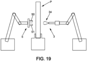
- said step b) of positioning and holding is implemented via a holding mechanism 5 comprising two clamps 50, 51, configured to hold said reinforcing element 1 in two positions, on either side, of the middle of the reinforcing element 1 along its length.
- the insertion tool which comprises the rod 30 is then actuated to pass through the bore 2 of the panel from the side opposite the side of the insertion Ci in the direction of the side of insertion and until the hook 31 at its distal end protrudes from the side of the insertion Ci, and as illustrated in figure 4 .
- the seizure of the reinforcing element 1 in step c) of seizure can be obtained while the hook 31 of the insertion tool is projecting from the insertion side, by moving the clamps 50,51 into engagement with the reinforcing element 1 from a position for which the reinforcing element does not cross the hook (ie figure 4 ) to a position in which an intermediate part such that the middle of said reinforcing element 1 passes through the hook (ie figure 5 ).
- the insertion tool 3 may comprise the rod 30 and the hook 31, but also a tube 33, the rod 30 and hook 31 assembly being mounted in the tube 33, in particular in a sliding manner with respect to the tube.
- the diameter of the tube is dimensioned with respect to the diameter of the drilling tool, namely substantially equal to or less than the diameter of the cylindrical body 40.
- the hook 31 is provided projecting from the mouth of the tube 33 when gripping the reinforcing element in step c).
- the hook 31 and the rod 30 are mounted to slide relative to the tube 33, the hook 31 is retracted within the tube 33, namely when the hook 31 is driven along the axis of the bore, from the insertion side towards the side of the panel opposite to that of the insertion during step d) of insertion.
- the hook 31 pulling the loop 12 is inside the tube 33, which is itself in the extension of the flush bore 2, as illustrated in the figure 7 , or even positioned slightly inboard as shown in figure 10 , on the side opposite to that of insertion: the loop 12 then housed in the tube 33.
- the retraction of the gripper (hook) in the tube makes it possible to constrain the loop within the tube, and thus advantageously to avoid friction (or stress) when the insertion tool pulls this loop over the length of the through bore.
- the method may also have a step e) of cutting successively to step d) of insertion, in which the loop 12 of the reinforcing element 1 is cut in the final position Pf of the reinforcing element 1.
- the reinforcing element can be divided into two sections of length 15, 16, each extending through the bore, and each exceeding the two sides of the panel by their ends 150, 151; 160, 161; and as shown in figure 8 .
- the two length sections can be provided flush with their ends 150, 151, 160, 161 on both sides of the panel, as illustrated in figure 11 .
- the two length sections can be provided flush on one side of the panel, and projecting on the other.
- step e) of cutting can be implemented by said insertion tool 3 which comprises a blade 32 mounted on the insertion tool movable relative to the hook 31: the loop 12 is cut during step e) by means of an actuating mechanism configured to pass said blade 32 from a retracted position at a distance from the hook 31, towards a cutting position in which said blade 32 cuts the loop 1 2 of reinforcement element 11 in pressing on the hook 31, with shearing effect between the blade 32 and the hook 31, if necessary the loop 12 held within the possible tube 33.
- a through reinforcement within the bore, for example consisting of a set of wires of a number equal to twice the number of wires of the reinforcing element of length L, of dimension L / 2 substantially equal to half the length L of the reinforcing element 1.
- step e) can be implemented while the loop 12 is positioned projecting from the panel on the side of the panel opposite the insertion side Ci in the final position Pf of the reinforcing element 1, by a cutting tool 6 separate from the insertion tool 3.
- This cutting tool cuts the loop 12 along an intermediate cutting plane between the hook 31 of the insertion tool 3 and the outer wall of the panel; this cut generating a fall 120 illustrated in dotted lines on the figure 12 formed by the fold of the loop 12 thus severed:
- This cutting tool can be an electric cutter, a rotary blade, mechanical scissors (for example pneumatic), an electric (or pneumatic) cutter, or else an ultrasonic cutting tool.
- a through reinforcement within the bore, for example consisting of a set of wires of a number equal to twice the number of wires of the reinforcing element of length L, of dimension slightly less than the dimension L / 2 substantially equal to half the length L of the reinforcing element 1, due to the drop 120.
- the cutting plane of the tool 6 can be substantially flush with the wall of the panel on the side opposite to the insertion side Ci, in order to obtain two sections of lengths 15, 16 crossing the bore with ends 151, 161 flush on this side and as illustrated in figure 11 .
- the cutting plane of the tool 5 can be moved away from the outer wall on the side opposite to the insertion side Ci, in order to obtain two sections of lengths 15, 16 with ends 151, 161 protruding from this side and as illustrated in figure 7 .
- step d) of insertion is carried out by the implementation of an insertion tool 3 which comprises a rod 30 configured to pass through the bore 2 of the panel from the side opposite to the insertion side Ci and in the direction of the insertion side Ci, said rod 30 being provided with a controlled clamp 34, at its distal end.
- This controlled clamp 34 projects from the insertion side Ci when the controlled clamp 34 grips the reinforcing element in step c), the controlled clamp 34 comprising two jaws 340, 341 configured to pass from an open position Po allowing the positioning of the reinforcing element 1 between the two jaws 340, 341 to a closed position Pfe in which the two jaws 340, 341 close on the reinforcing element 1 by gripping it, the insertion step d) ensuring the formation of the loop 12 around the controlled gripper 34 when the gripper is driven along the axis of the bore 2, from the insertion side Ci towards the side of the panel opposite that of the insertion.
- the insertion tool 3 comprises the rod 30 and the controlled clamp 34, but also a tube 33, the rod 30 and controlled clamp 34 assembly being slidably mounted in the tube 33.
- Said controlled gripper 34 is provided projecting from the mouth of the tube 33 when gripping the reinforcing element in step c), and in which the driven gripper 34 is retracted within the tube 33, when the driven gripper 34 is driven along the axis of the bore, from the insertion side towards the side of the panel opposite that of the insertion during the insertion step d).
- the retraction of the gripper (the gripper controlled) in the tube makes it possible to constrain the loop 12 within the tube 33, and thus advantageously to avoid friction (or constraints) when the insertion tool pulls this loop along the length of the through bore.
- the two bites 340, 341 of the clamp ordered 34 are formed by elastically deformable elements which, when protruding from the mouth of the tube 33, force the jaws 340,341, thanks to the elasticity of the elastically deformable elements, in the opening position Po where the bits 340, 341 extend radiically .
- the insertion tool is configured so that the passage of the jaws 340, 341 from the open position Po to the closed position Pfe is caused during the retraction of the clamp 34 within the tube 33 during which the two jaws 340, 341 are forced by the tube 33 to close on each other during the sliding of the rod 30 within the tube 33.
- This realization is clever. useful in that a single actuator makes it possible, by pulling on the rod, to retract the controlled clamp within the tube, but also to cause the jaws to close, or even by pushing on the rod to deploy the controlled clamp projecting from the mouth of the tube, but also to cause the opening of the jaws
- the cutting step e) is implemented by said insertion tool 3 which comprises a blade 32 mounted in the tube 33, movable relative to the controlled clamp 34: the loop 12 is cut during step e) by means of an actuating mechanism configured to pass said blade 32 from a retracted position at a distance from the controlled clamp 34 within the tube 33 in the closed position Pfe of the jaws 340, 341, to a cutting position in which said blade 32 severs loop 12 of reinforcing element 1 engaged with clamp 34 controlled within tube 33, with shearing effect between blade 32 and clamp 34.
- the blade 32 is arranged to slide; advantageously in an intermediate position between the two jaws 340, 341, configured to sever the loop of the reinforcing element 1 according to a cutting plane interposed between the two jaws 340, 341 of the gripper 34 then in the closed position Pfe.
- the risk of false cutting is limited, in particular for reinforcements of large section.
- step e) is implemented while the loop 12 is positioned projecting from the panel on the side of the panel opposite the insertion side Ci in the final position Pf of the reinforcing element, by a cutting tool 6 separate from the insertion tool 3 which cuts the loop 12 along an intermediate cutting plane between the gripper, on the one hand, consisting of the clamp 34 controlled by the insertion tool, and the wall of the panel, on the other hand , the cut generating a fall (formed by the loop fold 12.
- inclination it is understood that it can be a double inclination, namely a first inclination ⁇ , according to a first axis of rotation along a first direction parallel to the mean plane or to the mean surface of the panel, and a second inclination according to a second axis of rotation along a second direction parallel to the mean plane or to the mean surface of the panel and perpendicular to the first direction.
- the invention will also find a particular application for the implementation of a process for manufacturing a composite panel implementing the panel reinforcement process P in accordance with the invention in order to carry out insertions of reinforcing elements 1 in a panel P, each reinforcing element 1 being able to project from both sides of the panel, as for example illustrated in figure 8 , once the loop 12 has been severed, or even leveling on both sides of the panel as illustrated in figure 11 , once the loop has been severed, or even projecting from one side of the panel (Ci insertion side or opposite side) and leveling on the other side of the panel (opposite side or Ci insertion side) according to an embodiment not illustrated.
- the reinforcing element can be divided into two length sections 15, 16, each extending through the bore and each exceeding the two sides of the panel by their ends 150,151; 160,161; and as shown in figure 8 , or flush on both sides of the panel depending on the figure 11 or even projecting from one side of the panel (insertion side Ci or opposite side) and flush on the other side of the panel (opposite side or insertion side Ci) according to an embodiment not illustrated.
- two skins 17, 18 are added against the two sides of the panel P, the internal face of each skin facing the panel P in contact with the protruding/front-flush parts of the reinforcing elements 1, and as illustrated in figure 9 .
- the skins can be textile.
- a resin is then injected under vacuum impregnating the skins 17, 18 and the reinforcing elements 1 within the panel, with the creation of reinforcing bridges through the bores of the panels, each reinforcing bridge comprising a reinforcing element 1 impregnated with resin, the composite panel being obtained, after polymerization of the resin, with two skins 17, 18 connected respectively to the two sides of the panel, by their internal face, and the presence of reinforcing bridges in the form of the reinforcing element 1 impregnated with resin joining the skins 17, 18 between them.
- the reinforcing elements and the two skins comprise reinforcing fibers, and thermoplastic fibers and in which the skin and panel assembly reinforced by the reinforcing elements is heated, until the fusion of the thermoplastic fibers is obtained, the composite panel being obtained, after solidification by cooling of the thermoplastic polymer, with two skins linked by their internal face respectively to the two sides of the panel, and the presence of reinforcing bridges in the form of reinforcing fibers of the reinforcing elements impregnated with thermoplastic polymer joining the two skins between them.
- RTM Light technique which combines both the injection of the resin under a pressure greater than atmospheric pressure, but still less than or equal to 3 bars in the mold, and the placing under vacuum of the mold before injection of the resin, typically from 0.2 to 0.3 bars below atmospheric pressure, and which has the advantage of being less expensive in terms of equipment than the conventional RTM process operating at higher injection pressure.
- the counter-mold can be semi-rigid, in the form of a thick membrane, and not necessarily rigid as for a conventional RTM.
- the RTM Light finds a particular application for the transformation of low density foam panels such as polyethylene foams from 35 kg/m 3 to 50 kg/m 3 and whose cell structure, which is not very resistant to compression, does not allow transformation by the infusion technique because of the excessively high vacuum.
- a resin is injected under a pressure greater than atmospheric pressure at injection points in a mould, the injection pressure less than or equal to 3 bars, the mold maintained under vacuum between 0.2 and 0.3 bar below atmospheric pressure, the resin impregnating the skins 17, 18 and the reinforcing elements 1 within the panel, with the creation of reinforcing bridges through the bores of the panels, each reinforcing bridge comprising a reinforcing element 1 impregnated with resin, the composite panel being obtained, after polymerization of the resin, with two skins 17, 18 bonded respectively to the two sides of the panel, by their internal face, and the presence of reinforcing bridges in the form of the reinforcing element 1 impregnated with resin joining the skins 17, 18 together.
- the reinforcement process is noteworthy and advantageous in that it makes it possible to obtain reinforcement bridges between skins, with levels of reinforcement fibers greater than 30%, or even 40% by volume, in particular between 40% and 89%, by volume, or even between 45% and 89% by volume, or even between 40% and 80%, or even between 45% and 75%, or even between 45% and 70% by volume, namely a significant quantity of fibers compared to the polymerized resin of the reinforcement bridges.
- step d) Guaranteeing a controlled cylindrical surveyor bore, by minimizing the internal tensions, then makes it possible to insert the reinforcing element, in particular fibrous, according to step d) with a controlled packing in particular a section of the controlled reinforcing element, but without excess so as not to lose the cylindrical geometry giving the final shape of the reinforcing bridges during the application of the resin.
- said panel (excluding the skin) can be a multilayer of different densities and/or of different materials and/or having metal facing sheets. Par1, Par2.
- the possibility of providing reinforcement bridges of a substantial diameter makes it possible to reduce the surface density of the number of reinforcement bridges, but also to provide such reinforcements in panels of significant thickness.
- Example 1 Acrylic core material (PMI) reinforced by the process presented according to different core drilling diameters and whose bores were lined according to different filling ratios.
- Each line No. 1 to No. 9 of Table 2 provides for the insertion of two reinforcement elements (per line), according to the method of reinforcement according to the present disclosure.
- the loop formed at the end of the insertion step d) is cut dividing the reinforcing element into two length sections, protruding from the panel on these two faces
- the pair of parameters outside diameter ( ⁇ Ext) of the drilling tool/number of wires varies. It should be noted that the number of wires mentioned in the table is here double the number of wires of the reinforcing element when it is positioned in step b), i.e. the number of wires in the bore after the folding of the reinforcing element into the bore drilled in the panel at the end of step d).
- the vacuum is a vacuum of 0.9 bar below atmospheric pressure and which allows the migration of the epoxy resin impregnating the skins, but also the reinforcing threads within the drilled bores.
- the measurements of the reinforcement bridges are carried out after polymerization of the epoxy resin.
- Reinforcement bridge No. 1 and “ Reinforcement bridge No. 2 ”) are obtained in the form of threads impregnated with resin of generally cylindrical section.
- the measurement of the diameter of the reinforcement bridges is obtained using a caliper, after stripping the acrylic foam from the panel around the reinforcement bridges being measured.
- the fiber content in the reinforcement bridge (%m) is essentially determined according to the calcination method disclosed by NF EN ISO 1172 - Determination of textile glass and mineral filler content - Methods by calcination. » presented below.
- the table of the picture 2 thus presents the fiber content (in % by weight).
- Example 2 Polyurethane (PUR) core material reinforced by the process presented according to different core drilling diameters and whose bores were lined according to different filling ratios.
- [Table 3] Outer ⁇ (mm) Line No. Number of wires Reinforcement bridge n°1 Reinforcement bridge n°2 Diameter Fiber rate ⁇ (mm) Fiber rate (%m) ⁇ (mm) Fiber rate (%m) Avg (mm) standard deviation Avg (%m) standard deviation Avg (%Vf ) 4 1 36 3.19 74.2 3.21 74.5 3.2 0.01 74.3 0.2 56.7 2 44 3.23 79.2 3.27 78.8 3.25 0.03 79, 0.3 63.0 3 28 3.12 69.2 3.12 73.2 3.12 0 71.2 2.8 52.8 6 4 60 4.92 69.9 4.93 73.8 4.93 0.01 71.9 2.8 53.6 5 70 4.92 75.5 4.92 71.8 4.92 0 73.7 2.6 55.9 6 80 5 76.1 5.03 74.5 5.02 0.02
- Table 3 presents the results when the panel is a closed cell polyurethane foam, and according to the same protocol as in example 1
- the conversion of the fiber content by mass (% m) contained in the reinforcing bridge to a fiber content by volume (V fibre ) can be easily obtained by the formula of example 1 with the same values of density by volume ⁇ fibers and ⁇ resin .
- Example 3 Polyethylene (PE) core material reinforced by the process presented according to different coring diameters and whose bores were lined according to different filling ratios.
- Table 4 presents the results when the panel is a closed cell polyethylene foam, and according to the same protocol as in example 1
- the conversion of the fiber content by mass (% m) contained in the reinforcing bridge to a fiber content by volume (V fibre ) can be easily obtained by the formula of example 1 with the same values of density by volume ⁇ fibers and ⁇ resin .
- the method for determining the fiber content in the reinforcements is the calcination method presented in standard NF EN ISO 1172 - Determination of textile glass and mineral filler content - Methods by calcination. This method was used to determine %m in examples 1 to 3.
- the principle of the method is based on a mass difference between the mass of the complete composite reinforcement (glass fibers + thermosetting or thermoplastic matrix) and the mass of glass fibers of this same sample from which the matrix has been removed by calcination.
- the crucible or other container which will receive the composite reinforcement is subjected to the temperature chosen for calcination for a period of 10 minutes then, once cooled to room temperature, its mass is measured. The operation is repeated until a constant mass is obtained for the crucible.
- the composite reinforcement is placed in the previously prepared crucible and the assembly is dried at 105° C. until a constant mass is obtained.
- the mass of the assembly (crucible + composite reinforcement) is measured once the sample has returned to ambient temperature.
- the assembly is then placed in an oven having a temperature of 625° C. or else between 500° C. and 600° C. for materials (fibers or fillers) that do not support the first temperature set point in order to calcine the composite reinforcement and to recover only the reinforcing fibers present.
- the sample is kept in the drum until a constant mass is obtained.
- the oven temperature is 625°C for a period of 3 hours.
- the mass of the assembly (crucible + remaining fibres) is measured once at ambient temperature.
- the standard also specifies that a sample must weigh between 2 and 10g for composite laminates, which is not always possible for small diameter reinforcement bridges for examples 1 to 3. Also, and in examples 1 to 3, the measurements are to be carried out on a minimum of 2 samples (the most identical possible "reinforcement bridge No. 1 and "reinforcement bridge No. 2"). The result is an average of the two tests provided that the difference between the two measurements is less than 5%. If necessary, a third measurement is carried out on a 3rd sample most similar to the first two and the average of the 3 measurements is kept.
- the conversion of the mass content of fibers contained in the reinforcements to a density of fibers involves the densities of the matrix, of the reinforcing fibers and possibly of the composite (fiber + matrix).
- the densities of the components are either provided by the supplier of the raw material or are determined by the most appropriate means of measurement to quantify the volume of the element (Weighing with immersion in a solvent, determination of the volume by using a pycnometer or gas pycnometer (helium pycnometer). The mass of the element can be obtained by weighing elsewhere.
Landscapes
- Engineering & Computer Science (AREA)
- Mechanical Engineering (AREA)
- Chemical & Material Sciences (AREA)
- Composite Materials (AREA)
- Textile Engineering (AREA)
- Moulding By Coating Moulds (AREA)
- Laminated Bodies (AREA)
- Manufacturing Of Tubular Articles Or Embedded Moulded Articles (AREA)
- Body Structure For Vehicles (AREA)
- Panels For Use In Building Construction (AREA)
Priority Applications (3)
| Application Number | Priority Date | Filing Date | Title |
|---|---|---|---|
| RS20230954A RS64696B1 (sr) | 2019-07-08 | 2020-07-08 | Postupak za ojačavanje ploče i postupak za izradu kompozitne ploče primenom takvog postupka kao i kompozitna ploča dobijena na takav način |
| EP23180425.3A EP4238745B1 (fr) | 2019-07-08 | 2020-07-08 | Procede de renforcement d'un panneau et un procede de fabrication de panneau composite mettant en oeuvre un tel procede |
| HRP20231335TT HRP20231335T1 (hr) | 2019-07-08 | 2020-07-08 | Postupak ojačavanja panela i postupak proizvodnje kompozitnog panela primjenom takvog postupka, te tako načinjeni kompozitni panel |
Applications Claiming Priority (2)
| Application Number | Priority Date | Filing Date | Title |
|---|---|---|---|
| FR1907623A FR3098444B1 (fr) | 2019-07-08 | 2019-07-08 | Procédé de renforcement d’un panneau et un procédé de fabrication de panneau composite mettant en œuvre un tel procédé |
| PCT/EP2020/069244 WO2021005107A1 (fr) | 2019-07-08 | 2020-07-08 | Procede de renforcement d'un panneau et un procede de fabrication de panneau composite mettant en oeuvre un tel procede |
Related Child Applications (1)
| Application Number | Title | Priority Date | Filing Date |
|---|---|---|---|
| EP23180425.3A Division EP4238745B1 (fr) | 2019-07-08 | 2020-07-08 | Procede de renforcement d'un panneau et un procede de fabrication de panneau composite mettant en oeuvre un tel procede |
Publications (3)
| Publication Number | Publication Date |
|---|---|
| EP3996901A1 EP3996901A1 (fr) | 2022-05-18 |
| EP3996901C0 EP3996901C0 (fr) | 2023-07-26 |
| EP3996901B1 true EP3996901B1 (fr) | 2023-07-26 |
Family
ID=68733203
Family Applications (2)
| Application Number | Title | Priority Date | Filing Date |
|---|---|---|---|
| EP20736712.9A Active EP3996901B1 (fr) | 2019-07-08 | 2020-07-08 | Procede de renforcement d'un panneau et un procede de fabrication de panneau composite mettant en oeuvre un tel procede et panneau composite ainsi obtenu |
| EP23180425.3A Active EP4238745B1 (fr) | 2019-07-08 | 2020-07-08 | Procede de renforcement d'un panneau et un procede de fabrication de panneau composite mettant en oeuvre un tel procede |
Family Applications After (1)
| Application Number | Title | Priority Date | Filing Date |
|---|---|---|---|
| EP23180425.3A Active EP4238745B1 (fr) | 2019-07-08 | 2020-07-08 | Procede de renforcement d'un panneau et un procede de fabrication de panneau composite mettant en oeuvre un tel procede |
Country Status (17)
| Country | Link |
|---|---|
| US (1) | US11951693B2 (pl) |
| EP (2) | EP3996901B1 (pl) |
| JP (1) | JP7817150B2 (pl) |
| KR (1) | KR102880162B1 (pl) |
| CN (1) | CN114080317B (pl) |
| AU (1) | AU2020309155B2 (pl) |
| CA (1) | CA3143900A1 (pl) |
| ES (1) | ES2960949T3 (pl) |
| FR (1) | FR3098444B1 (pl) |
| HR (1) | HRP20231335T1 (pl) |
| HU (1) | HUE063659T2 (pl) |
| MX (1) | MX2022000391A (pl) |
| PL (1) | PL3996901T3 (pl) |
| RS (1) | RS64696B1 (pl) |
| SA (1) | SA522431306B1 (pl) |
| WO (1) | WO2021005107A1 (pl) |
| ZA (1) | ZA202200332B (pl) |
Family Cites Families (21)
| Publication number | Priority date | Publication date | Assignee | Title |
|---|---|---|---|---|
| US3030256A (en) | 1960-03-08 | 1962-04-17 | Rosenthal Harry | Reinforced laminated panels with foam core |
| JPS59192498A (ja) * | 1983-04-15 | 1984-10-31 | 株式会社アイジー技術研究所 | 複合材用穿孔装置 |
| GB9014770D0 (en) * | 1990-07-03 | 1990-08-22 | Short Brothers Plc | Manufacture of a composite material |
| DE4330402A1 (de) * | 1993-08-12 | 1995-02-16 | Manfred Dr Gehring | Kantenschutzrichtwinkel als Eckbewehrung |
| JP3594668B2 (ja) * | 1994-11-01 | 2004-12-02 | 株式会社イノアックコーポレーション | 弾性発泡体の穴開け方法 |
| JPH09267207A (ja) * | 1996-04-03 | 1997-10-14 | Cosmo Koki Co Ltd | 管体穿孔用ホールソー |
| JP2909819B1 (ja) * | 1998-05-20 | 1999-06-23 | 次郎 苗代 | 回転ポンチによる布地の孔明け装置 |
| JP3602069B2 (ja) * | 2001-06-01 | 2004-12-15 | 株式会社ミヤナガ | コアドリルのコア体結合構造 |
| US20050183813A1 (en) * | 2002-01-31 | 2005-08-25 | Gonsalves James F. | Process for manufacturing a composite sheet |
| WO2005018926A2 (en) * | 2003-03-28 | 2005-03-03 | Webcore Technologies, Inc. | Fiber reinforced composite cores and panels |
| DE102005024408A1 (de) * | 2005-05-27 | 2006-11-30 | Airbus Deutschland Gmbh | Verstärkung von Schaumwerkstoffen |
| DE102005024828A1 (de) | 2005-05-27 | 2007-03-15 | Xella Technologie- Und Forschungsgesellschaft Mbh | Befestigungsvorrichtung |
| DE102005035681A1 (de) | 2005-07-27 | 2007-02-08 | Röhm Gmbh | Fertigungsverfahren zur Armierung von Kernmaterialien für Kernverbunde sowie von Kernverbund-Strukturen |
| US7891096B2 (en) * | 2007-01-23 | 2011-02-22 | Airbus Deutschland Gmbh | Method for reinforcing a foam material as well as a sandwich component |
| DE102008001826B3 (de) * | 2008-05-16 | 2009-09-17 | Airbus Deutschland Gmbh | Ausschnittverstärkung für Kernverbunde sowie ein Verfahren zum Herstellen einer Ausschnittverstärkung für Kernverbunde |
| JP2012020330A (ja) * | 2010-07-16 | 2012-02-02 | Muramoto Kosakusho:Kk | バーリング加工方法及びバーリング加工具 |
| JP5678933B2 (ja) * | 2012-08-08 | 2015-03-04 | オイレス工業株式会社 | 薄板金属の孔明け用のパンチを具備した薄板金属の孔明け装置 |
| DE102012023815B4 (de) * | 2012-12-05 | 2016-04-28 | Airbus Operations Gmbh | Vielnadelmaschine und Verfahren zur Herstellung von verstärkten Materialien |
| FR3029834B1 (fr) | 2014-12-10 | 2019-06-07 | Doyen Entreprises | Procede pour l'insertion et la mise en place de fils individuels au travers d'un panneau |
| EP3173216B1 (en) * | 2015-11-26 | 2018-04-11 | Airbus Operations GmbH | Method and needle for reinforcing cellular materials |
| WO2017202669A1 (de) * | 2016-05-25 | 2017-11-30 | Basf Se | Faserverstärkte schaumstoffe |
-
2019
- 2019-07-08 FR FR1907623A patent/FR3098444B1/fr active Active
-
2020
- 2020-07-08 HU HUE20736712A patent/HUE063659T2/hu unknown
- 2020-07-08 CA CA3143900A patent/CA3143900A1/fr active Pending
- 2020-07-08 US US17/624,789 patent/US11951693B2/en active Active
- 2020-07-08 WO PCT/EP2020/069244 patent/WO2021005107A1/fr not_active Ceased
- 2020-07-08 AU AU2020309155A patent/AU2020309155B2/en active Active
- 2020-07-08 RS RS20230954A patent/RS64696B1/sr unknown
- 2020-07-08 JP JP2022501198A patent/JP7817150B2/ja active Active
- 2020-07-08 EP EP20736712.9A patent/EP3996901B1/fr active Active
- 2020-07-08 ES ES20736712T patent/ES2960949T3/es active Active
- 2020-07-08 KR KR1020227000469A patent/KR102880162B1/ko active Active
- 2020-07-08 EP EP23180425.3A patent/EP4238745B1/fr active Active
- 2020-07-08 HR HRP20231335TT patent/HRP20231335T1/hr unknown
- 2020-07-08 MX MX2022000391A patent/MX2022000391A/es unknown
- 2020-07-08 CN CN202080049392.4A patent/CN114080317B/zh active Active
- 2020-07-08 PL PL20736712.9T patent/PL3996901T3/pl unknown
-
2022
- 2022-01-06 SA SA522431306A patent/SA522431306B1/ar unknown
- 2022-01-06 ZA ZA2022/00332A patent/ZA202200332B/en unknown
Also Published As
| Publication number | Publication date |
|---|---|
| WO2021005107A1 (fr) | 2021-01-14 |
| EP3996901C0 (fr) | 2023-07-26 |
| MX2022000391A (es) | 2022-04-18 |
| KR20220031612A (ko) | 2022-03-11 |
| JP2022541155A (ja) | 2022-09-22 |
| ZA202200332B (en) | 2023-11-29 |
| EP3996901A1 (fr) | 2022-05-18 |
| AU2020309155A1 (en) | 2022-02-03 |
| RS64696B1 (sr) | 2023-11-30 |
| EP4238745C0 (fr) | 2025-12-10 |
| CN114080317B (zh) | 2024-04-09 |
| JP7817150B2 (ja) | 2026-02-18 |
| SA522431306B1 (ar) | 2023-11-08 |
| PL3996901T3 (pl) | 2024-02-05 |
| AU2020309155B2 (en) | 2026-01-29 |
| US11951693B2 (en) | 2024-04-09 |
| BR112022000206A2 (pt) | 2022-02-22 |
| US20220250336A1 (en) | 2022-08-11 |
| EP4238745A2 (fr) | 2023-09-06 |
| FR3098444B1 (fr) | 2021-10-01 |
| EP4238745B1 (fr) | 2025-12-10 |
| CA3143900A1 (fr) | 2021-01-14 |
| HRP20231335T1 (hr) | 2024-02-16 |
| FR3098444A1 (fr) | 2021-01-15 |
| HUE063659T2 (hu) | 2024-01-28 |
| KR102880162B1 (ko) | 2025-11-04 |
| EP4238745A3 (fr) | 2023-12-13 |
| CN114080317A (zh) | 2022-02-22 |
| ES2960949T3 (es) | 2024-03-07 |
Similar Documents
| Publication | Publication Date | Title |
|---|---|---|
| EP0916477B2 (fr) | ProcÚdÚ de moulage d'une piÞce composite, et structure composite employÚe dans ce procÚdÚ | |
| EP2282877B1 (fr) | Procédé de fabrication d'une pièce à corps creux en matériau composite et pièce ainsi obtenue | |
| EP3052286B1 (fr) | Ensemble de compactage et procede de fabrication d'une aube composite de turbomachine | |
| CA2926170C (fr) | Procede et ensemble de fabrication d'aube composite | |
| CA2727249C (fr) | Procede de fabrication d'une piece structurale en materiau composite a matrice organique, piece obtenue | |
| FR3017819A1 (fr) | Renfort fibreux pour la realisation d'une piece mecanique allongee en materiau composite | |
| EP0013648B1 (fr) | Procédé pour la réalisation d'une bielle de commande ou de transmission d'efforts | |
| EP2974854B1 (fr) | Procede de fabrication d'un longeron d'une pale, et de fabrication d'une pale | |
| FR3046563A1 (fr) | Outillage de maintien en forme et de transport pour preforme fibreuse et procede de fabrication d'une piece en materiau composite | |
| FR3046564A1 (fr) | Outillage de levage et de transport pour preforme fibreuse et procede de fabrication d'une piece en materiau composite | |
| EP4238745B1 (fr) | Procede de renforcement d'un panneau et un procede de fabrication de panneau composite mettant en oeuvre un tel procede | |
| EP2974851B1 (fr) | Procédé de fabrication d'un longeron d'une pale, et une pale | |
| FR2993492A1 (fr) | Procede de fabrication d'une piece composite en t par moulage par transfert de resine | |
| EP2593295A1 (fr) | Procede de fabrication d'une ame de bielle en materiau composite, et ame de bielle obtenue | |
| WO2013139714A2 (fr) | Procédé pour la fabrication d'un cadre de hublot en matériau composite a renfort fibreux et hublot obtenu par un tel procédé | |
| FR2671757A1 (fr) | Structures creuses allongees en materiaux composites et procedes de fabrication. |
Legal Events
| Date | Code | Title | Description |
|---|---|---|---|
| REG | Reference to a national code |
Ref country code: HR Ref legal event code: TUEP Ref document number: P20231335T Country of ref document: HR |
|
| STAA | Information on the status of an ep patent application or granted ep patent |
Free format text: STATUS: UNKNOWN |
|
| STAA | Information on the status of an ep patent application or granted ep patent |
Free format text: STATUS: THE INTERNATIONAL PUBLICATION HAS BEEN MADE |
|
| PUAI | Public reference made under article 153(3) epc to a published international application that has entered the european phase |
Free format text: ORIGINAL CODE: 0009012 |
|
| STAA | Information on the status of an ep patent application or granted ep patent |
Free format text: STATUS: REQUEST FOR EXAMINATION WAS MADE |
|
| 17P | Request for examination filed |
Effective date: 20220118 |
|
| AK | Designated contracting states |
Kind code of ref document: A1 Designated state(s): AL AT BE BG CH CY CZ DE DK EE ES FI FR GB GR HR HU IE IS IT LI LT LU LV MC MK MT NL NO PL PT RO RS SE SI SK SM TR |
|
| DAV | Request for validation of the european patent (deleted) | ||
| DAX | Request for extension of the european patent (deleted) | ||
| GRAP | Despatch of communication of intention to grant a patent |
Free format text: ORIGINAL CODE: EPIDOSNIGR1 |
|
| STAA | Information on the status of an ep patent application or granted ep patent |
Free format text: STATUS: GRANT OF PATENT IS INTENDED |
|
| INTG | Intention to grant announced |
Effective date: 20230217 |
|
| GRAS | Grant fee paid |
Free format text: ORIGINAL CODE: EPIDOSNIGR3 |
|
| GRAA | (expected) grant |
Free format text: ORIGINAL CODE: 0009210 |
|
| STAA | Information on the status of an ep patent application or granted ep patent |
Free format text: STATUS: THE PATENT HAS BEEN GRANTED |
|
| RAP1 | Party data changed (applicant data changed or rights of an application transferred) |
Owner name: ASCODERO PRODUCTIQUE Owner name: SICOMIN HOLDING |
|
| AK | Designated contracting states |
Kind code of ref document: B1 Designated state(s): AL AT BE BG CH CY CZ DE DK EE ES FI FR GB GR HR HU IE IS IT LI LT LU LV MC MK MT NL NO PL PT RO RS SE SI SK SM TR |
|
| REG | Reference to a national code |
Ref country code: CH Ref legal event code: EP |
|
| REG | Reference to a national code |
Ref country code: IE Ref legal event code: FG4D Free format text: LANGUAGE OF EP DOCUMENT: FRENCH |
|
| REG | Reference to a national code |
Ref country code: DE Ref legal event code: R096 Ref document number: 602020014506 Country of ref document: DE |
|
| U01 | Request for unitary effect filed |
Effective date: 20230808 |
|
| U07 | Unitary effect registered |
Designated state(s): AT BE BG DE DK EE FI FR IT LT LU LV MT NL PT SE SI Effective date: 20230814 |
|
| REG | Reference to a national code |
Ref country code: NO Ref legal event code: T2 Effective date: 20230726 |
|
| REG | Reference to a national code |
Ref country code: LT Ref legal event code: MG9D |
|
| PG25 | Lapsed in a contracting state [announced via postgrant information from national office to epo] |
Ref country code: GR Free format text: LAPSE BECAUSE OF FAILURE TO SUBMIT A TRANSLATION OF THE DESCRIPTION OR TO PAY THE FEE WITHIN THE PRESCRIBED TIME-LIMIT Effective date: 20231027 |
|
| PG25 | Lapsed in a contracting state [announced via postgrant information from national office to epo] |
Ref country code: IS Free format text: LAPSE BECAUSE OF FAILURE TO SUBMIT A TRANSLATION OF THE DESCRIPTION OR TO PAY THE FEE WITHIN THE PRESCRIBED TIME-LIMIT Effective date: 20231126 |
|
| REG | Reference to a national code |
Ref country code: HU Ref legal event code: AG4A Ref document number: E063659 Country of ref document: HU |
|
| PG25 | Lapsed in a contracting state [announced via postgrant information from national office to epo] |
Ref country code: IS Free format text: LAPSE BECAUSE OF FAILURE TO SUBMIT A TRANSLATION OF THE DESCRIPTION OR TO PAY THE FEE WITHIN THE PRESCRIBED TIME-LIMIT Effective date: 20231126 Ref country code: GR Free format text: LAPSE BECAUSE OF FAILURE TO SUBMIT A TRANSLATION OF THE DESCRIPTION OR TO PAY THE FEE WITHIN THE PRESCRIBED TIME-LIMIT Effective date: 20231027 |
|
| REG | Reference to a national code |
Ref country code: SK Ref legal event code: T3 Ref document number: E 42741 Country of ref document: SK |
|
| REG | Reference to a national code |
Ref country code: HR Ref legal event code: T1PR Ref document number: P20231335 Country of ref document: HR |
|
| REG | Reference to a national code |
Ref country code: ES Ref legal event code: FG2A Ref document number: 2960949 Country of ref document: ES Kind code of ref document: T3 Effective date: 20240307 |
|
| REG | Reference to a national code |
Ref country code: DE Ref legal event code: R097 Ref document number: 602020014506 Country of ref document: DE |
|
| PG25 | Lapsed in a contracting state [announced via postgrant information from national office to epo] |
Ref country code: SM Free format text: LAPSE BECAUSE OF FAILURE TO SUBMIT A TRANSLATION OF THE DESCRIPTION OR TO PAY THE FEE WITHIN THE PRESCRIBED TIME-LIMIT Effective date: 20230726 |
|
| PLBE | No opposition filed within time limit |
Free format text: ORIGINAL CODE: 0009261 |
|
| STAA | Information on the status of an ep patent application or granted ep patent |
Free format text: STATUS: NO OPPOSITION FILED WITHIN TIME LIMIT |
|
| 26N | No opposition filed |
Effective date: 20240429 |
|
| REG | Reference to a national code |
Ref country code: HR Ref legal event code: ODRP Ref document number: P20231335 Country of ref document: HR Payment date: 20240619 Year of fee payment: 5 |
|
| U20 | Renewal fee for the european patent with unitary effect paid |
Year of fee payment: 5 Effective date: 20240617 |
|
| PG25 | Lapsed in a contracting state [announced via postgrant information from national office to epo] |
Ref country code: MC Free format text: LAPSE BECAUSE OF FAILURE TO SUBMIT A TRANSLATION OF THE DESCRIPTION OR TO PAY THE FEE WITHIN THE PRESCRIBED TIME-LIMIT Effective date: 20230726 |
|
| PGFP | Annual fee paid to national office [announced via postgrant information from national office to epo] |
Ref country code: PL Payment date: 20250624 Year of fee payment: 6 |
|
| PGFP | Annual fee paid to national office [announced via postgrant information from national office to epo] |
Ref country code: RS Payment date: 20250624 Year of fee payment: 6 |
|
| PGFP | Annual fee paid to national office [announced via postgrant information from national office to epo] |
Ref country code: HR Payment date: 20250623 Year of fee payment: 6 |
|
| REG | Reference to a national code |
Ref country code: HR Ref legal event code: ODRP Ref document number: P20231335 Country of ref document: HR Payment date: 20250623 Year of fee payment: 6 |
|
| PGFP | Annual fee paid to national office [announced via postgrant information from national office to epo] |
Ref country code: TR Payment date: 20250623 Year of fee payment: 6 Ref country code: SK Payment date: 20250624 Year of fee payment: 6 |
|
| PGFP | Annual fee paid to national office [announced via postgrant information from national office to epo] |
Ref country code: CZ Payment date: 20250623 Year of fee payment: 6 |
|
| U20 | Renewal fee for the european patent with unitary effect paid |
Year of fee payment: 6 Effective date: 20250627 |
|
| PGFP | Annual fee paid to national office [announced via postgrant information from national office to epo] |
Ref country code: HU Payment date: 20250725 Year of fee payment: 6 |
|
| PGFP | Annual fee paid to national office [announced via postgrant information from national office to epo] |
Ref country code: ES Payment date: 20250811 Year of fee payment: 6 |
|
| PGFP | Annual fee paid to national office [announced via postgrant information from national office to epo] |
Ref country code: NO Payment date: 20250728 Year of fee payment: 6 |
|
| PGFP | Annual fee paid to national office [announced via postgrant information from national office to epo] |
Ref country code: GB Payment date: 20250723 Year of fee payment: 6 |
|
| PGFP | Annual fee paid to national office [announced via postgrant information from national office to epo] |
Ref country code: CH Payment date: 20250801 Year of fee payment: 6 |
|
| PGFP | Annual fee paid to national office [announced via postgrant information from national office to epo] |
Ref country code: IE Payment date: 20250728 Year of fee payment: 6 |
|
| PGFP | Annual fee paid to national office [announced via postgrant information from national office to epo] |
Ref country code: RO Payment date: 20250708 Year of fee payment: 6 |
|
| PG25 | Lapsed in a contracting state [announced via postgrant information from national office to epo] |
Ref country code: CY Free format text: LAPSE BECAUSE OF FAILURE TO SUBMIT A TRANSLATION OF THE DESCRIPTION OR TO PAY THE FEE WITHIN THE PRESCRIBED TIME-LIMIT; INVALID AB INITIO Effective date: 20200708 |