EP3996319B1 - Aktivierung und deaktivierung semipersistenter csi-berichterstattung - Google Patents
Aktivierung und deaktivierung semipersistenter csi-berichterstattung Download PDFInfo
- Publication number
- EP3996319B1 EP3996319B1 EP21215760.6A EP21215760A EP3996319B1 EP 3996319 B1 EP3996319 B1 EP 3996319B1 EP 21215760 A EP21215760 A EP 21215760A EP 3996319 B1 EP3996319 B1 EP 3996319B1
- Authority
- EP
- European Patent Office
- Prior art keywords
- csi
- csi reporting
- activation
- deactivation
- reporting
- Prior art date
- Legal status (The legal status is an assumption and is not a legal conclusion. Google has not performed a legal analysis and makes no representation as to the accuracy of the status listed.)
- Active
Links
Images


Classifications
-
- H—ELECTRICITY
- H04—ELECTRIC COMMUNICATION TECHNIQUE
- H04B—TRANSMISSION
- H04B7/00—Radio transmission systems, i.e. using radiation field
- H04B7/02—Diversity systems; Multi-antenna system, i.e. transmission or reception using multiple antennas
- H04B7/04—Diversity systems; Multi-antenna system, i.e. transmission or reception using multiple antennas using two or more spaced independent antennas
- H04B7/06—Diversity systems; Multi-antenna system, i.e. transmission or reception using multiple antennas using two or more spaced independent antennas at the transmitting station
- H04B7/0613—Diversity systems; Multi-antenna system, i.e. transmission or reception using multiple antennas using two or more spaced independent antennas at the transmitting station using simultaneous transmission
- H04B7/0615—Diversity systems; Multi-antenna system, i.e. transmission or reception using multiple antennas using two or more spaced independent antennas at the transmitting station using simultaneous transmission of weighted versions of same signal
- H04B7/0619—Diversity systems; Multi-antenna system, i.e. transmission or reception using multiple antennas using two or more spaced independent antennas at the transmitting station using simultaneous transmission of weighted versions of same signal using feedback from receiving side
- H04B7/0621—Feedback content
- H04B7/0626—Channel coefficients, e.g. channel state information [CSI]
-
- H—ELECTRICITY
- H04—ELECTRIC COMMUNICATION TECHNIQUE
- H04B—TRANSMISSION
- H04B7/00—Radio transmission systems, i.e. using radiation field
- H04B7/02—Diversity systems; Multi-antenna system, i.e. transmission or reception using multiple antennas
- H04B7/04—Diversity systems; Multi-antenna system, i.e. transmission or reception using multiple antennas using two or more spaced independent antennas
- H04B7/06—Diversity systems; Multi-antenna system, i.e. transmission or reception using multiple antennas using two or more spaced independent antennas at the transmitting station
- H04B7/0613—Diversity systems; Multi-antenna system, i.e. transmission or reception using multiple antennas using two or more spaced independent antennas at the transmitting station using simultaneous transmission
- H04B7/0615—Diversity systems; Multi-antenna system, i.e. transmission or reception using multiple antennas using two or more spaced independent antennas at the transmitting station using simultaneous transmission of weighted versions of same signal
- H04B7/0619—Diversity systems; Multi-antenna system, i.e. transmission or reception using multiple antennas using two or more spaced independent antennas at the transmitting station using simultaneous transmission of weighted versions of same signal using feedback from receiving side
- H04B7/0636—Feedback format
- H04B7/0645—Variable feedback
-
- H—ELECTRICITY
- H04—ELECTRIC COMMUNICATION TECHNIQUE
- H04L—TRANSMISSION OF DIGITAL INFORMATION, e.g. TELEGRAPHIC COMMUNICATION
- H04L1/00—Arrangements for detecting or preventing errors in the information received
- H04L1/0001—Systems modifying transmission characteristics according to link quality, e.g. power backoff
- H04L1/0002—Systems modifying transmission characteristics according to link quality, e.g. power backoff by adapting the transmission rate
- H04L1/0003—Systems modifying transmission characteristics according to link quality, e.g. power backoff by adapting the transmission rate by switching between different modulation schemes
-
- H—ELECTRICITY
- H04—ELECTRIC COMMUNICATION TECHNIQUE
- H04L—TRANSMISSION OF DIGITAL INFORMATION, e.g. TELEGRAPHIC COMMUNICATION
- H04L1/00—Arrangements for detecting or preventing errors in the information received
- H04L1/0001—Systems modifying transmission characteristics according to link quality, e.g. power backoff
- H04L1/0023—Systems modifying transmission characteristics according to link quality, e.g. power backoff characterised by the signalling
- H04L1/0026—Transmission of channel quality indication
-
- H—ELECTRICITY
- H04—ELECTRIC COMMUNICATION TECHNIQUE
- H04L—TRANSMISSION OF DIGITAL INFORMATION, e.g. TELEGRAPHIC COMMUNICATION
- H04L1/00—Arrangements for detecting or preventing errors in the information received
- H04L1/0001—Systems modifying transmission characteristics according to link quality, e.g. power backoff
- H04L1/0023—Systems modifying transmission characteristics according to link quality, e.g. power backoff characterised by the signalling
- H04L1/0027—Scheduling of signalling, e.g. occurrence thereof
-
- H—ELECTRICITY
- H04—ELECTRIC COMMUNICATION TECHNIQUE
- H04L—TRANSMISSION OF DIGITAL INFORMATION, e.g. TELEGRAPHIC COMMUNICATION
- H04L1/00—Arrangements for detecting or preventing errors in the information received
- H04L1/12—Arrangements for detecting or preventing errors in the information received by using return channel
- H04L1/16—Arrangements for detecting or preventing errors in the information received by using return channel in which the return channel carries supervisory signals, e.g. repetition request signals
- H04L1/18—Automatic repetition systems, e.g. Van Duuren systems
- H04L1/1812—Hybrid protocols; Hybrid automatic repeat request [HARQ]
- H04L1/1819—Hybrid protocols; Hybrid automatic repeat request [HARQ] with retransmission of additional or different redundancy
-
- H—ELECTRICITY
- H04—ELECTRIC COMMUNICATION TECHNIQUE
- H04L—TRANSMISSION OF DIGITAL INFORMATION, e.g. TELEGRAPHIC COMMUNICATION
- H04L5/00—Arrangements affording multiple use of the transmission path
- H04L5/0001—Arrangements for dividing the transmission path
- H04L5/0014—Three-dimensional division
- H04L5/0016—Time-frequency-code
-
- H—ELECTRICITY
- H04—ELECTRIC COMMUNICATION TECHNIQUE
- H04L—TRANSMISSION OF DIGITAL INFORMATION, e.g. TELEGRAPHIC COMMUNICATION
- H04L5/00—Arrangements affording multiple use of the transmission path
- H04L5/003—Arrangements for allocating sub-channels of the transmission path
- H04L5/0053—Allocation of signalling, i.e. of overhead other than pilot signals
- H04L5/0057—Physical resource allocation for CQI
-
- H—ELECTRICITY
- H04—ELECTRIC COMMUNICATION TECHNIQUE
- H04L—TRANSMISSION OF DIGITAL INFORMATION, e.g. TELEGRAPHIC COMMUNICATION
- H04L5/00—Arrangements affording multiple use of the transmission path
- H04L5/003—Arrangements for allocating sub-channels of the transmission path
- H04L5/0078—Timing of allocation
- H04L5/0082—Timing of allocation at predetermined intervals
-
- H—ELECTRICITY
- H04—ELECTRIC COMMUNICATION TECHNIQUE
- H04L—TRANSMISSION OF DIGITAL INFORMATION, e.g. TELEGRAPHIC COMMUNICATION
- H04L5/00—Arrangements affording multiple use of the transmission path
- H04L5/0091—Signalling for the administration of the divided path, e.g. signalling of configuration information
- H04L5/0096—Indication of changes in allocation
- H04L5/0098—Signalling of the activation or deactivation of component carriers, subcarriers or frequency bands
-
- H—ELECTRICITY
- H04—ELECTRIC COMMUNICATION TECHNIQUE
- H04W—WIRELESS COMMUNICATION NETWORKS
- H04W24/00—Supervisory, monitoring or testing arrangements
- H04W24/10—Scheduling measurement reports ; Arrangements for measurement reports
-
- H—ELECTRICITY
- H04—ELECTRIC COMMUNICATION TECHNIQUE
- H04W—WIRELESS COMMUNICATION NETWORKS
- H04W72/00—Local resource management
- H04W72/12—Wireless traffic scheduling
-
- H—ELECTRICITY
- H04—ELECTRIC COMMUNICATION TECHNIQUE
- H04W—WIRELESS COMMUNICATION NETWORKS
- H04W72/00—Local resource management
- H04W72/20—Control channels or signalling for resource management
-
- H—ELECTRICITY
- H04—ELECTRIC COMMUNICATION TECHNIQUE
- H04W—WIRELESS COMMUNICATION NETWORKS
- H04W72/00—Local resource management
- H04W72/20—Control channels or signalling for resource management
- H04W72/23—Control channels or signalling for resource management in the downlink direction of a wireless link, i.e. towards a terminal
- H04W72/232—Control channels or signalling for resource management in the downlink direction of a wireless link, i.e. towards a terminal the control data signalling from the physical layer, e.g. DCI signalling
-
- H—ELECTRICITY
- H04—ELECTRIC COMMUNICATION TECHNIQUE
- H04L—TRANSMISSION OF DIGITAL INFORMATION, e.g. TELEGRAPHIC COMMUNICATION
- H04L5/00—Arrangements affording multiple use of the transmission path
- H04L5/0091—Signalling for the administration of the divided path, e.g. signalling of configuration information
- H04L5/0094—Indication of how sub-channels of the path are allocated
Definitions
- the present disclosure relates to a wireless communication system and, more specifically, to activation and deactivation of semi-persistent Channel State Information (CSI) reporting by a wireless device.
- CSI Channel State Information
- the next generation mobile wireless communication system which is referred to as Third Generation Partnership Project (3GPP) Fifth Generation (5G) or New Radio (NR), will support a diverse set of use cases and a diverse set of deployment scenarios.
- 3GPP Third Generation Partnership Project
- 5G Fifth Generation
- NR New Radio
- the latter includes deployment at both low frequencies in the range of hundreds of megahertz (MHz), similar to Long Term Evolution (LTE) today, and very high frequencies referred to as millimeter wave (mmW) in the range of tens of gigahertz (GHz).
- MHz Megahertz
- LTE Long Term Evolution
- mmW millimeter wave
- NR will use Orthogonal Frequency Division Multiplexing (OFDM) in the downlink from a NR base station (gNB) to a User Equipment device (UE).
- OFDM Orthogonal Frequency Division Multiplexing
- gNB NR base station
- UE User Equipment device
- DFT Discrete Fourier Transform
- the basic NR physical resource can thus be seen as a time-frequency grid as illustrated in Figure 1 , where each Resource Element (RE) corresponds to one OFDM subcarrier during one OFDM symbol interval.
- Resource allocation in a slot is described in terms of Resource Blocks (RBs) in the frequency domain and number of OFDM symbols in the time domain.
- RBs Resource Blocks
- a RB corresponds to 12 contiguous subcarriers and a slot consists of 14 OFDM symbols.
- NR Different subcarrier spacing values are supported in NR.
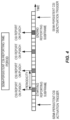
- downlink and uplink transmissions in NR are organized into equally-sized subframes similar to LTE as shown in Figure 2 .
- a subframe is further divided into slots and the number of slots per subframe is 2 ⁇ +1 for a numerology of (15 ⁇ 2 ⁇ ) kHz.
- the NR supports "slot based" transmission.
- the gNB transmits Downlink Control Information (DCI) about which UE data is to be transmitted to and what resources in the current downlink subframe the data is transmitted on.
- the DCI is carried on the Physical Downlink Control Channel (PDCCH) and data is carried on the Physical Downlink Shared Channel (PDSCH).
- PDCH Physical Downlink Control Channel
- PDSCH Physical Downlink Shared Channel
- This PDCCH is typically transmitted in Control Resource Sets (CORSETs) in the first few OFDM symbols in each slot.
- CORSETs Control Resource Sets
- a UE first decodes PDCCH and if a PDCCH is decoded successfully, it then decodes the corresponding PDSCH based on the decoded DCI in the PDCCH.
- Uplink data transmissions are also dynamically scheduled using PDCCH. Similar to downlink, a UE first decodes an uplink grant in a DCI carried by PDCCH and then transmits data over the Physical Uplink Shared Channel (PUSCH) based on the decoded control information in the uplink grant such as modulation order, coding rate, uplink resource allocation, etc. Each UE is assigned a unique Cell Radio Network Temporary Identifier (C-RNTI) during network connection.
- C-RNTI Cell Radio Network Temporary Identifier
- the Cyclic Redundancy Check (CRC) bits attached to a DCI for a UE are scrambled by the UE's C-RNTI, so a UE recognizes its own DCI by checking the CRC bits of the DCI against the assigned C-RNTI.
- uplink DCI For uplink scheduling over PUSCH, at least the following bit fields are included in an uplink DCI:
- CSI feedback is used by the gNB to obtain downlink CSI from a UE in order to determine how to transmit downlink data to a UE over a plurality of antenna ports.
- CSI typically includes a channel Rank Indicator (RI), a Precoding Matrix Indicator (PMI), and a Channel Quality Indicator (CQI).
- RI is used to indicate the number of data layers that can be transmitted simultaneously to a UE
- PMI is used to indicate the precoding matrix for the indicated data layers
- CQI is used to indicate the modulation and coding rate that can be achieved with the indicated rank and the precoding matrix.
- NR in addition to periodic and aperiodic CSI reporting as in LTE, semi-persistent CSI reporting is also supported.
- three types of CSI reporting will be supported in NR as follows:
- CSI-RS CSI Reference Signal
- CSI-RS is used for measuring downlink CSI by a UE.
- CSI-RS is transmitted over each transmit (Tx) antenna port at the gNB and for different antenna ports and the CSI-RSs are multiplexed in time, frequency, and code domain such that the channel between each Tx antenna port at the gNB and each receive antenna port at a UE can be measured by the UE.
- a time frequency resource used for transmitting CSI-RS is referred to as a CSI-RS resource.
- a UE can be configured with N ⁇ 1 CSI reporting settings (i.e., ReportConfigs), M ⁇ 1 resource settings (i.e., ResourceConfigs), and one CSI measurement setting, where the CSI measurement setting includes L ⁇ 1 measurement links (i.e., MeasLinkConfigs). At least the following configuration parameters are signaled via RRC for CSI acquisition.
- A-CSI reporting over PUSCH is triggered by a DCI for scheduling PUSCH or uplink DCI.
- a special CSI request bit field in the DCI is defined for the purpose.
- Each value of the CSI request bit field defines a codepoint and each codepoint can be associated with a higher layer configured CSI report trigger state.
- the CSI report trigger states contains a list of S c measurement links associated with A-CSI reporting.
- Each CSI report trigger state defines at least the following information:
- the bit width, L c , of the CSI request field is configurable from 0 to 6 bits.
- S c When the number of CSI triggering states, S c , is larger than the number of codepoints, i.e. S c > 2 L c - 1, a Medium Access Control (MAC) Control Element (CE) is used to select a subset of 2 L c - 1 triggering states from the S c triggering states so that there is a one-to-one mapping between each codepoint and a CSI triggering state.
- the 2 L c - 1 is due to the fact that one codepoint with setting the CSI request field to all zeroes is used to indicate no triggered report.
- Figure 3 provides an illustration of A-CSI reporting.
- Figure 4 illustrates SP-CSI reporting over PUSCH. It has been agreed that SP-CSI reporting over PUSCH is activated using DCI, and the CSI is reported on PUSCH periodically until the SP-CSI reporting is deactivated, also by DCI, as shown in Figure 4 .
- a set of SP-CSI report settings, or SP-CSI report trigger states are higher layer configured by Semi-persistent-on-PUSCHReportTrigger and the CSI request field in DCI scrambled with SP-CSI C-RNTI activates one of the SP-CSI reports or trigger states.
- a SP-CSI report trigger state may comprise one or more of a SP-CSI report setting configuration, a SP-CSI resource setting configuration for channel measurement, and a SP-CSI resource setting configuration for interference measurement. When only a single SP-CSI resource is allowed, then a SP-CSI report trigger state is equivalent to one or more SP-CSI report settings.
- a UE performs SP-CSI reporting on the PUSCH upon successful decoding an uplink DCI format.
- the uplink DCI format will contain one or more CSI Reporting Setting Indications where the associated CSI Measurement Links and CSI Resource Settings are higher layer configured.
- SP-CSI reporting on the PUSCH supports Type I and Type II CSI with wideband, partial band, and sub-band frequency granularities.
- the PUSCH resources and MCS are allocated semi-persistently by an uplink DCI.
- the gNB or UE consists of a number protocol layers, including Physical (PHY) layer, MAC layer, and RRC layer.
- the PHY layer is also referred to as Layer 1 (L1).
- the MAC layer is part of Layer 2 (L2), which also includes Radio Link Control (RLC), Packet Data Convergence Protocol (PDCP), and Service Data Adaptation Protocol (SDAP) layers.
- Layers above PHY are also referred to as higher layers, such as MAC and RRC. Part of the MAC function is to perform data scheduling while part of the RRC function is to establish, maintain, and release radio link connection between a gNB and a UE.
- the gNB can also semi-statically allocate resources for Configured Scheduling (CS) or Semi-Persistent Scheduling (SPS):
- CS Configured Scheduling
- SPS Semi-Persistent Scheduling
- RRC configures at least the following parameters when the configured grant Type 1 is configured:
- RRC configures at least the following parameters when the configured grant Type 2 is configured:
- the UE does not transmit anything on the resources configured by the RRC if the higher layers did not deliver a Transport Block (TB) to transmit on the resources allocated for SPS transmission.
- TB Transport Block
- a set of allowed periodicities P are defined in table 6.1.2.3-1 of 38.214, which is copied below, where CP is for Cyclic Prefix type.
- Table 6.1.2.3-1: Allowed periodicities P for uplink transmission without grant ⁇ CP Possible values of periodicities P [symbols] 0 Normal 2, 7, n*14, where n ⁇ 1, 2, 5, 10.
- Proposal 2 The same confirmation mechanism in LTE Rel-8 for UL SPS activation/deactivation can be used for SP-CSI.
- Proposal 3 SP-CSI specific C-RNTI is supported for SP-CSI.
- Proposal 4 SP-CSI re-activation that updates the resource assignment or other parameters is supported.
- Proposal 5 Retransmissions are not supported for SP-CSI on PUSCH.
- Proposal 6 Uplink MIMO is supported for SP-CSI on PUSCH.
- Proposal 7 The same UCI encoding for A-CSI on PUSCH is used for SP-CSI UCI encoding on PUSCH.
- Proposal 3 Support BWP-specific CSI configurations where separate independent instances of CSI report settings are configured for each candidate BWP, each mapping to independent Resource Settings.
- Proposal 4 Do not reporting CSI corresponding to a non-active BWP if the active and non-active BWPs span different PRBs.
- Proposal 5 A BWP spanning a subset of PRBs of another BWP can reuse the same CSI configuration as that BWP.
- Proposal 6 Adopt the additional CSI periodicities in Table 1 to ensure alignment between P-CSI reporting and DRX cycles for all supported subcarrier spacings.
- Proposal 7 For priority rules for CSI collision, the following definition is used: "Two CSI reports are said to collide if the time occupancy of the physical channels scheduled to carry the CSI reports overlap in at least one OFDM symbol and are transmitted on the same carrier".
- Proposal 8 For P/SP CSI collisions where all colliding CSIs are transmitted on PUCCH, the CSI with the longest periodicity has priority while the other CSIs are dropped.
- Proposal 9 Extend the agreed priority rules for CSI collision in RAN1#90b also to when Type I and Type II CSI collides.
- Proposal 10 Adopt the refined subband sizes and ranges in Table 2.
- Proposal 11 If configured to be present for a CSI report setting, the indicator of strongest DL layer within the CW with highest CQI for DL PTRS port mapping purpose, the so called CPI, is jointly encoded with RI into a single field using at most one additional bit compared to standalone RI field.
- Proposal 12 The same set of RRC configured PUSCH timing offsets Y is used for PUSCH with and without piggybacked CSI.
- Proposal 13 SP-CSI reporting on PUCCH is activated with DCI.
- Proposal 14 SP-CSI reporting on PUCCH uses semi-statically configured PUCCH resources.
- Proposal 15 Confirm the working assumption to support A-CSI on short PUCCH for Y>0.
- a method performed by a wireless device, a wireless device, a method performed by a base station and a base station are defined by the appended independent claims 1, 5, 6, 7 respectively.
- the invention is defined by the appended claims.
- Radio Node As used herein, a "radio node” is either a radio access node or a wireless device.
- Radio Access Node As used herein, a "radio access node” or “radio network node” is any node in a radio access network of a cellular communications network that operates to wirelessly transmit and/or receive signals.
- a radio access node include, but are not limited to, a base station (e.g., a New Radio (NR) base station (gNB) in a Third Generation Partnership Project (3GPP) Fifth Generation (5G) NR network or an enhanced or evolved Node B (eNB) in a 3GPP Long Term Evolution (LTE) network), a high-power or macro base station, a low-power base station (e.g., a micro base station, a pico base station, a home eNB, or the like), and a relay node.
- a base station e.g., a New Radio (NR) base station (gNB) in a Third Generation Partnership Project (3GPP) Fifth Generation (5G) NR network or an enhanced or evolved Node B (eNB) in a
- a "core network node” is any type of node in a core network.
- Some examples of a core network node include, e.g., a Mobility Management Entity (MME), a Packet Data Network Gateway (P-GW), a Service Capability Exposure Function (SCEF), or the like.
- MME Mobility Management Entity
- P-GW Packet Data Network Gateway
- SCEF Service Capability Exposure Function
- a “wireless device” is any type of device that has access to (i.e., is served by) a cellular communications network by wirelessly transmitting and/or receiving signals to a radio access node(s).
- a wireless device include, but are not limited to, a User Equipment device (UE) in a 3GPP network and a Machine Type Communication (MTC) device.
- UE User Equipment device
- MTC Machine Type Communication
- Network Node As used herein, a "network node” is any node that is either part of the radio access network or the core network of a cellular communications network/system.
- DCI Downlink Control Information
- C-RNTI SP-CSI Cell Radio Network Temporary Identifier
- the embodiment may provide one or more of the following technical advantage(s).
- the solutions allow a UE to distinguish between an activation DCI and a deactivation DCI for SP-CSI reporting.
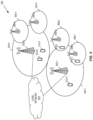
- FIG. 5 illustrates an example of a cellular communications network 500 according to the embodiment of the present disclosure.
- the cellular communications network 500 is a 5G NR network.
- the cellular communications network 500 includes base stations 502-1 and 502-2, which in 5G NR are referred to as gNBs, controlling corresponding macro cells 504-1 and 504-2.
- the base stations 502-1 and 502-2 are generally referred to herein collectively as base stations 502 and individually as base station 502.
- the macro cells 504-1 and 504-2 are generally referred to herein collectively as macro cells 504 and individually as macro cell 504.
- the cellular communications network 500 may also include a number of low power nodes 506-1 through 506-4 controlling corresponding small cells 508-1 through 508-4.
- the low power nodes 506-1 through 506-4 can be small base stations (such as pico or femto base stations) or Remote Radio Heads (RRHs), or the like. Notably, while not illustrated, one or more of the small cells 508-1 through 508-4 may alternatively be provided by the base stations 502.
- the low power nodes 506-1 through 506-4 are generally referred to herein collectively as low power nodes 506 and individually as low power node 506.
- the small cells 508-1 through 508-4 are generally referred to herein collectively as small cells 508 and individually as small cell 508.
- the base stations 502 (and optionally the low power nodes 506) are connected to a core network 510.
- the base stations 502 and the low power nodes 506 provide service to wireless devices 512-1 through 512-5 in the corresponding cells 504 and 508.
- the wireless devices 512-1 through 512-5 are generally referred to herein collectively as wireless devices 512 and individually as wireless device 512.
- the wireless devices 512 are also sometimes referred to herein as UEs.
- FIG. 6 illustrates an example of the operation of a network node (e.g., a base station 502) and a wireless device 512 to provide activation/deactivation of SP-CSI reporting.
- the network node sends, to the wireless device 512, a control message (e.g., an Uplink (UL) DCI which is also referred to herein as an UL DCI message) for activation or deactivation of SP-SCI reporting (step 600).
- the control message is also for uplink grant free data transmission, as described below in detail.
- control message is an UL DCI message that is scrambled with an identifier of the wireless device 512 (e.g., a SP-CSI C-RNTI of the wireless device 512), where the wireless device 512 is to toggle between activation and deactivation of SP-CSI reporting upon receiving the UL DCI message that is scrambled with its SP-CSI C-RNTI.
- control message is an UL DCI message that is scrambled with an identifier of the wireless device 512 (e.g., a SP-CSI C-RNTI of the wireless device 512) and includes information that indicates whether the control message is for activation of SP-CSI reporting or deactivation of SP-CSI reporting.
- this information may be one or more bits in one or more fields that are defined for other purposes and reused to provide an indication of whether the message is for activation or deactivation of SP-CSI reporting, as described in more detail below.
- this information is one or more bits of a CSI Request Field included in the UL DCI message.
- this information is indicated by a SP-CSI trigger state indicated by the UL DCI message, where separate SP-CSI trigger states are defined for activation of SP-CSI reporting and deactivation of SP-CSI reporting.
- information included in the UL DCI message and a current state of the wireless device 512 are both taken into account to determine whether to activate or deactivate SP-CSI reporting and, in unclaimed examples, whether to activate or deactivate uplink grant free transmission at the wireless device 512.
- the wireless device 512 Upon receiving the control message, the wireless device 512 determines whether the control message is for activation of SP-CSI reporting or for deactivation of SP-CSI reporting (step 602). In an unclaimed example, the wireless device 512 also determines whether the message is for activation of uplink grant free data transmission or for deactivation of uplink grant free data transmission. In some examples, this process includes determining that the control message is scrambled with the identity (e.g., SP-CSI C-RNTI) of the wireless device 512 and, if so, proceeding to determine whether to activate or deactivate SP-CSI reporting based on the message. The wireless device 512 then activates or deactivates SP-CSI reporting in accordance with the determination made in step 602 (step 604).
- identity e.g., SP-CSI C-RNTI
- SP-CSI activation and deactivation indication is to toggle between activation and deactivation (or release).
- the first transmitted UL DCI scrambled with SP-CSI C-RNTI is for SP-CSI activation.
- the second SP-CSI DCI following the first SP-CSI DCI is for deactivation (or release) of the SP-CSI activated by the first SP-CSI DCI.
- the third SP-CSI DCI following the second SP-CSI is for activation of a new SP-CSI
- the fourth SP-CSI DCI following the third SP-CSI DCI is for deactivation of the SP-CSI activated by the third SP-CSI DCI, and so on.
- An example is shown in Figure 7 .
- the drawback of this toggling approach is that it may prevent reconfiguration of an on-going SP-CSI reporting on PUSCH.
- the gNB may want to change the resource allocation or modulation order for an ongoing SP-CSI; this cannot be done with the toggling approach as a UE could treat a reconfiguration SP-CSI DCI as for deactivation.
- a UE missed a SP-CSI DCI due to, for example, decoding error then the subsequent SP-CSI reporting would be wrong.
- the UE can assume that the second SP-CSI DCI has deactivated the SP-CSI reporting on PUSCH. For instance, if the modulation order or resource allocation indicated by the first and second SP-CSI DCIs is the same, then the UE can assume that the second SP-CSI DCI has deactivated the SP-CSI reporting on PUSCH. However, if one or more bit field values between the first and second SP-CSI DCIs are different, then the UE can assume that the second SP-CSI DCI has reconfigured the SP-CSI reporting on PUSCH. For example, if the modulation order or resource allocation indicated by the first and second SP-CSI DCIs is different, then the UE can assume that the second SP-CSI DCI has reconfigured the SP-CSI reporting on PUSCH.
- Figure 8 illustrates an unclaimed example of the operation of a network node (e.g., the base station 502) and the wireless device 512 in accordance with Unclaimed example 1.
- the network node sends, to the wireless device 512, a first control message (e.g., a first UL DCI message that is scrambled with the identity (e.g., SP-CSI C-RNTI) of the wireless device 512) for activation/deactivation of SP-CSI reporting (step 800).
- the wireless device 512 determines that the control message is for activation of SP-CSI reporting since the control message is the first control message received by the wireless device 512 for activation or deactivation of SP-CSI reporting (step 802).
- the wireless device 512 activates SP-CSI reporting (step 804).
- the network node sends a second control message (e.g., a second UL DCI message that is scrambled with the identity (e.g., SP-CSI C-RNTI) of the wireless device 512) for activation/deactivation of SP-CSI reporting (step 806).
- a second control message e.g., a second UL DCI message that is scrambled with the identity (e.g., SP-CSI C-RNTI) of the wireless device 512
- the wireless device 512 determines that the control message is for deactivation of SP-CSI reporting since the control message is the second control message received by the wireless device 512 for activation or deactivation of SP-CSI reporting (step 808).
- the wireless device 512 deactivates SP-CSI reporting (step 810).
- the process can continue in this manner. In this way, the wireless device 512 toggles between activation and deactivation of SP-CSI reporting upon receiving the control messages.
- the determination to deactivate SP-CSI reporting in step 808 further includes a determination whether the values in one or more predefined fields in the second control message are the same as the values for the same field(s) in the first control message. If so, the wireless device 512 determines that SP-CSI reporting is to be deactivated. If not, the wireless device 512 determines that SP-CSI reporting is to remain activated.
- Example 1 - Reuse Some Bit Field in UL DCI for Activation and Deactivation Indication For uplink data transmission on PUSCH, when a decoding error occurs at the gNB, the gNB may request a retransmission of the data by a UE. For this purpose, the UE keeps a copy of the original data in its transmission buffer until a DCI with a New Data Indication (NDI) is received from the gNB for the same Hybrid Automatic Repeat Request (HARQ) process. When a retransmission is needed, the gNB typically sends another uplink grant in DCI with the "New Data Indication" bit set to "0" and the "Redundancy Version” bit field set to a desired value.
- NDI New Data Indication
- HARQ Hybrid Automatic Repeat Request
- the "New Data Indication” bit may be used for SP-CSI activation and deactivation indication. After a UE detects an UL DCI scrambled by its SP-CSI C-RNTI, the UE can further check the "New Data Indication” bit to determine whether it is for SP-CSI activation or deactivation. For example, the bit is set to "0" for activation and to "1" for deactivation. This allows for reconfiguration of an ongoing SP-CSI by sending a new activation DCI with new parameters such as a new resource allocation or a new modulation order. An example is shown in Figure 9 .
- the 2 bit "Redundancy Version” field in the UL DCI can be used for the purpose.
- the bits are set to "00" for activation and to "11" for deactivation.
- Embodiment - Reuse More Than One Bit Field in UL DCI for Activation and Deactivation Indication To further enhance the validation reliability for SP-CSI activation or deactivation, more than one bit field in UL DCI may be used.
- a UE For SP-CSI activation validation, a UE first validates a SP-CSI DCI in a Physical Downlink Control Channel (PDCCH) by verifying that the Cyclic Redundancy Check (CRC) bits of the DCI are scrambled by SP-CSI C-RNTI. As an example, the UE further verifies that at least one or all of the following conditions are met:
- PDCCH Physical Downlink Control Channel
- CRC Cyclic Redundancy Check
- a UE For SP-CSI deactivation or release validation, a UE first validates a SP-CSI DCI in a PDCCH by verifying that the CRC bits of the DCI are scrambled by SP-CSI C-RNTI. As an example, the UE further verifies that at least one or all of the following conditions are met:
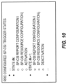
- Unclaimed example 2 - Use One Bit in the CSI Request Field in UL DCI for Activation and Deactivation Indication Another option is to use one bit in the CSI request bit field for activation and deactivation indication and the rest of the bits in the CSI request field for selecting a SP-CSI trigger state. However, when the configured number of bits in the CSI request field is small, this would reduce the number of SP-CSI trigger states that can be supported. Furthermore, if only one bit for the CSI request field is configured, then this option would not allow more than one SP-CSI trigger state, which is a limitation. This option doesn't work when the zero bit is configured for the CSI request field.
- SP-CSI activation and deactivation are defined as part of the SP-CSI trigger states, in which case for each SP-CSI reporting configuration and resource configuration, two states are configured - one for activation and the other for deactivation, as shown in Figure 10 .
- the codepoint of the CSI request field is used to indicate a joint SP-CSI reporting configuration, resource configuration, and SP-CSI activation or deactivation.
- SP-CSI state #k is indicated by the CSI request field in DCI, it is for SP-CSI activation. Otherwise, if SP-CSI state #k+1 is indicated by the CSI request field in DCI, it is for SP-CSI deactivation.
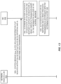
- Figure 11 illustrates one example of the operation of a network node (e.g., the base station 502) and the wireless device 512 in accordance with any one of the Embodiment and examples 1-4.
- the network node sends, to the wireless device 512, a control message (e.g., a UL DCI message that is scrambled with the identity (e.g., SP-CSI C-RNTI) of the wireless device 512) that includes infor-mation that indicates activation of SP-CSI reporting or indicates deactivation of SP-CSI reporting (step 1100).
- the information included in the control message is one or more bits in a field that are reused for purposes of indicating activation or deactivation of SP-CSI reporting.
- this information includes bits in multiple fields of the control message.
- this information includes a bit(s) in the CSI Request Field in the DCI that indicates whether the message is for activation or for deactivation of SP-CSI reporting.
- this information includes information that indicates the SP-CSI trigger state, where different SP-CSI trigger states are predefined or preconfigured for activation and deactivation of SP-CSI reporting.
- the wireless device 512 determines whether the control message is for activation of SP-CSI reporting or deactivation of SP-CSI reporting based on the information included in the control message (step 1102). More specifically, using an UL DCI message as an example, the wireless device 512 determines that the UL DCI message is scrambled with the SP-CSI C-RNTI of the wireless device 512. By determining that the UL DCI message is scrambled with the SP-CSI C-RNTI of the wireless device 512, the wireless device 512 can validate that the control message is intended for the wireless device 512 and that the control message is either for activation or for deactivation of SP-CSI.
- the wireless device 512 determines whether the UL DCI message is for activation or for deactivation of SP-CSI reporting based on the information included in the UL DCI message, as described above with respect to any one of the Embodiment and (unclaimed) examples 2-5.
- the wireless device 512 activates or deactivates SP-CSI reporting in accordance with the determination made in step 1102 (step 1104).
- This uplink grant allows the UE to convey Uplink Shared Channel (UL-SCH) on the PUSCH using uplink grant free transmission (i.e., SPS) and may optionally allow transmission of a SP-CSI report. If SPS is activated, UL-SCH may always be mapped to the PUSCH from a Medium Access Control (MAC) perspective.
- MAC Medium Access Control
- Uplink Control Information (which comprises the CSI report) is supposed to be multiplexed with the transport blocks provided by UL-SCH on L1 by mapping UCI to the allocated resource first, it may be possible to convey only SP-CSI reports on PUSCH if the resource allocation for the PUSCH is set appropriately by the gNB so that only the content of the CSI reports fits in the PUSCH payload.
- UCI Uplink Control Information
- SPS and SP-CSI reporting are activated with the same UL DCI message.
- Said UL DCI message may be differentiated from dynamic uplink grants due to CRC being scrambled with a certain Radio Network Temporary Identifier (RNTI), such as a configured Configured Scheduling (CS) RNTI.
- RNTI Radio Network Temporary Identifier
- the activation DCI may be additionally identified by the setting of a combination of certain bit fields in the DCI. In one unclaimed example, the bit fields set according to:
- the gNB may send a deactivation DCI message (which may also be CRC scrambled with a CS-RNTI).
- a deactivation DCI message (which may also be CRC scrambled with a CS-RNTI).
- the semi-persistent PUSCH transmission is stopped, implying that both SPS and any active SP-CSI reporting is deactivated.
- the CSI request field may be ignored in the deactivation DCI, and any SP-CSI report that is active is deactivated anyway regardless of if the CSI request field is equal to "0" or not.
- the format of the deactivation DCI may assert that the CSI request field is set to "0" in order to further provide DCI detection reliability for the deactivation DCI.
- the deactivation DCI may be identified by setting a certain combination of bit fields to certain values. For instance, the bit fields may be set according to:
- FIG 12 one Unclaimed example 4 is illustrated with a state transition diagram, identifying to which state the UE moves upon reception of the different DCI messages.
- any number of SP-CSI report settings may be supported and each activated SP-CSI report corresponds to a state, but only two states (#1 and #N) for activated SP-CSI reports is shown in Figure 12 , for readability, but it is implied that from the illustration that omitted SP-CSI report states #2, #3, ..., #N-1 are present as well.
- SP-CSI reporting may not be activated without SPS also being activated.
- the "states” refer to Radio Resource Control (RRC) configured SP-CSI trigger states.
- RRC Radio Resource Control
- a DCI may simultaneously activate one or more SP-CSI report settings, such that the one or more SP-CSI reports are transmitted on the same PUSCH.
- the UE stops SP-CSI reporting on the SP-CSI reports associated with the previously active SP-CSI trigger state and commences SP-CSI reporting on the SP-CSI report settings associated with the SP-CSI trigger state identified with the CSI request field in the activation DCI message.
- Figure 13 illustrates the operation of a network node (e.g., the base station 502) and the wireless device 512 in accordance with Unclaimed Example 4.
- the network node sends, to the wireless device 512, a control message (e.g., a UL DCI message that is scrambled with the identity (e.g., CS-CSI C-RNTI) of the wireless device 512) that includes information that indicates activation or deactivation of SP-CSI reporting and activation or deactivation of uplink grant free data transmission (e.g., SPS data transmission) (step 1300).
- a control message e.g., a UL DCI message that is scrambled with the identity (e.g., CS-CSI C-RNTI) of the wireless device 512
- uplink grant free data transmission e.g., SPS data transmission
- the wireless device 512 Upon receiving the control message, the wireless device 512 determines whether the control message is for activation of SP-CSI reporting or deactivation of SP-CSI reporting as well as for activation of uplink grant free data transmission or deactivation of uplink grant free data transmission based on the information included in the control message and a current state of the wireless device 512 (step 1302), as described above. The wireless device 512 activates or deactivates SP-CSI reporting in accordance with the determination made in step 1302 (step 1304).
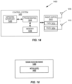
- FIG. 14 is a schematic block diagram of a radio access node 1400 according to the embodiment of the present disclosure.
- the radio access node 1400 may be, for example, a base station 502 or 506.
- the radio access node 1400 includes a control system 1402 that includes one or more processors 1404 (e.g., Central Processing Units (CPUs), Application Specific Integrated Circuits (ASICs), Field Programmable Gate Arrays (FPGAs), and/or the like), memory 1406, and a network interface 1408.
- the radio access node 1400 includes one or more radio units 1410 that each includes one or more transmitters 1412 and one or more receivers 1414 coupled to one or more antennas 1416.
- the radio unit(s) 1410 is external to the control system 1402 and connected to the control system 1402 via, e.g., a wired connection (e.g., an optical cable). However, in some other embodiments, the radio unit(s) 1410 and potentially the antenna(s) 1416 are integrated together with the control system 1402.
- the one or more processors 1404 operate to provide one or more functions of a radio access node 1400 as described herein. In some embodiments, the function(s) are implemented in software that is stored, e.g., in the memory 1406 and executed by the one or more processors 1404.
- Figure 15 is a schematic block diagram that illustrates a virtualized example of the radio access node 1400. This discussion is equally applicable to other types of network nodes. Further, other types of network nodes may have similar virtualized architectures.
- a "virtualized" radio access node is an implementation of the radio access node 1400 in which at least a portion of the functionality of the radio access node 1400 is implemented as a virtual component(s) (e.g., via a virtual machine(s) executing on a physical processing node(s) in a network(s)).
- the radio access node 1400 includes the control system 1402 that includes the one or more processors 1404 (e.g., CPUs, ASICs, FPGAs, and/or the like), the memory 1406, and the network interface 1408 and the one or more radio units 1410 that each includes the one or more transmitters 1412 and the one or more receivers 1414 coupled to the one or more antennas 1416, as described above.
- the control system 1402 is connected to the radio unit(s) 1410 via, for example, an optical cable or the like.
- the control system 1402 is connected to one or more processing nodes 1500 coupled to or included as part of a network(s) 1502 via the network interface 1408.
- Each processing node 1500 includes one or more processors 1504 (e.g., CPUs, ASICs, FPGAs, and/or the like), memory 1506, and a network interface 1508.
- functions 1510 of the radio access node 1400 described herein are implemented at the one or more processing nodes 1500 or distributed across the control system 1402 and the one or more processing nodes 1500 in any desired manner.
- some or all of the functions 1510 of the radio access node 1400 described herein are implemented as virtual components executed by one or more virtual machines implemented in a virtual environment(s) hosted by the processing node(s) 1500.
- additional signaling or communication between the processing node(s) 1500 and the control system 1402 is used in order to carry out at least some of the desired functions 1510.
- the control system 1402 may not be included, in which case the radio unit(s) 1410 communicate directly with the processing node(s) 1500 via an appropriate network interface(s).
- a computer program including instructions which, when executed by at least one processor, causes the at least one processor to carry out the functionality of radio access node 1400 or a node (e.g., a processing node 1500) implementing one or more of the functions 1510 of the radio access node 1400 in a virtual environment according to any of the examples described herein is provided.
- a carrier comprising the aforementioned computer program product is provided. The carrier is one of an electronic signal, an optical signal, a radio signal, or a computer readable storage medium (e.g., a non-transitory computer readable medium such as memory).
- FIG 16 is a schematic block diagram of the radio access node 1400 according to an unclaimed example.
- the radio access node 1400 includes one or more modules 1600, each of which is implemented in software.
- the module(s) 1600 provide the functionality of the radio access node 1400 described herein. This discussion is equally applicable to the processing node 1500 of Figure 15 where the modules 1600 may be implemented at one of the processing nodes 1500 or distributed across multiple processing nodes 1500 and/or distributed across the processing node(s) 1500 and the control system 1402.
- FIG 17 is a schematic block diagram of a UE 1700 according to the embodiment of the present disclosure.
- the UE 1700 includes one or more processors 1702 (e.g., CPUs, ASICs, FPGAs, and/or the like), memory 1704, and one or more transceivers 1706 each including one or more transmitters 1708 and one or more receivers 1710 coupled to one or more antennas 1712.
- processors 1702 e.g., CPUs, ASICs, FPGAs, and/or the like
- memory 1704 e.g., RAM, programmable gate array, and/or the like
- transceivers 1706 each including one or more transmitters 1708 and one or more receivers 1710 coupled to one or more antennas 1712.
- the functionality of the UE 1700 described above may be fully or partially implemented in software that is, e.g., stored in the memory 1704 and executed by the processor(s) 1702.
- a computer program including instructions which, when executed by at least one processor, causes the at least one processor to carry out the functionality of the UE 1700 according to any of the examples described herein is provided.
- a carrier comprising the aforementioned computer program product is provided.
- the carrier is one of an electronic signal, an optical signal, a radio signal, or a computer readable storage medium (e.g., a non-transitory computer readable medium such as memory).
- FIG 18 is a schematic block diagram of the UE 1700 according to an unclaimed example.
- the UE 1700 includes one or more modules 1800, each of which is implemented in software.
- the module(s) 1800 provide the functionality of the UE 1700 described herein.
- a communication system includes a telecommunication network 1900, such as a 3GPP-type cellular network, which comprises an access network 1902, such as a Radio Access Network (RAN), and a core network 1904.
- the access network 1902 comprises a plurality of base stations 1906A, 1906B, 1906C, such as Node Bs, eNBs, gNBs, or other types of wireless Access Points (APs), each defining a corresponding coverage area 1908A, 1908B, 1908C.
- Each base station 1906A, 1906B, 1906C is connectable to the core network 1904 over a wired or wireless connection 1910.
- a first UE 1912 located in coverage area 1908C is configured to wirelessly connect to, or be paged by, the corresponding base station 1906C.
- a second UE 1914 in coverage area 1908A is wirelessly connectable to the corresponding base station 1906A. While a plurality of UEs 1912, 1914 are illustrated in this example, the disclosed examples are equally applicable to a situation where a sole UE is in the coverage area or where a sole UE is connecting to the corresponding base station 1906.
- the telecommunication network 1900 is itself connected to a host computer 1916, which may be embodied in the hardware and/or software of a standalone server, a cloud-implemented server, a distributed server, or as processing resources in a server farm.
- the host computer 1916 may be under the ownership or control of a service provider, or may be operated by the service provider or on behalf of the service provider.
- Connections 1918 and 1920 between the telecommunication network 1900 and the host computer 1916 may extend directly from the core network 1904 to the host computer 1916 or may go via an optional intermediate network 1922.
- the intermediate network 1922 may be one of, or a combination of more than one of, a public, private, or hosted network; the intermediate network 1922, if any, may be a backbone network or the Internet; in particular, the intermediate network 1922 may comprise two or more sub-networks (not shown).
- the communication system of Figure 19 as a whole enables connectivity between the connected UEs 1912, 1914 and the host computer 1916.
- the connectivity may be described as an Over-the-Top (OTT) connection 1924.
- the host computer 1916 and the connected UEs 1912, 1914 are configured to communicate data and/or signaling via the OTT connection 1924, using the access network 1902, the core network 1904, any intermediate network 1922, and possible further infrastructure (not shown) as intermediaries.
- the OTT connection 1924 may be transparent in the sense that the participating communication devices through which the OTT connection 1924 passes are unaware of routing of uplink and downlink communications.
- the base station 1906 may not or need not be informed about the past routing of an incoming downlink communication with data originating from the host computer 1916 to be forwarded (e.g., handed over) to a connected UE 1912. Similarly, the base station 1906 need not be aware of the future routing of an outgoing uplink communication originating from the UE 1912 towards the host computer 1916.
- a host computer 2002 comprises hardware 2004 including a communication interface 2006 configured to set up and maintain a wired or wireless connection with an interface of a different communication device of the communication system 2000.
- the host computer 2002 further comprises processing circuitry 2008, which may have storage and/or processing capabilities.
- the processing circuitry 2008 may comprise one or more programmable processors, ASICs, FPGAs, or combinations of these (not shown) adapted to execute instructions.
- the host computer 2002 further comprises software 2010, which is stored in or accessible by the host computer 2002 and executable by the processing circuitry 2008.
- the software 2010 includes a host application 2012.
- the host application 2012 may be operable to provide a service to a remote user, such as a UE 2014 connecting via an OTT connection 2016 terminating at the UE 2014 and the host computer 2002. In providing the service to the remote user, the host application 2012 may provide user data which is transmitted using the OTT connection 2016.
- the communication system 2000 further includes a base station 2018provided in a telecommunication system and comprising hardware 2020 enabling it to communicate with the host computer 2002 and with the UE 2014.
- the hardware 2020 may include a communication interface 2022 for setting up and maintaining a wired or wireless connection with an interface of a different communication device of the communication system 2000, as well as a radio interface 2024 for setting up and maintaining at least a wireless connection 2026 with the UE 2014 located in a coverage area (not shown in Figure 20 ) served by the base station 2018.
- the communication interface 2022 may be configured to facilitate a connection 2028 to the host computer 2002.
- connection 2028 may be direct or it may pass through a core network (not shown in Figure 20 ) of the telecommunication system and/or through one or more intermediate networks outside the telecommunication system.
- the hardware 2020 of the base station 2018 further includes processing circuitry 2030, which may comprise one or more programmable processors, ASICs, FPGAs, or combinations of these (not shown) adapted to execute instructions.
- the base station 2018 further has software 2032 stored internally or accessible via an external connection.
- the communication system 2000 further includes the UE 2014 already referred to.
- the UE's 2014 hardware 2034 may include a radio interface 2036 configured to set up and maintain a wireless connection 2026 with a base station serving a coverage area in which the UE 2014 is currently located.
- the hardware 2034 of the UE 2014 further includes processing circuitry 2038, which may comprise one or more programmable processors, ASICs, FPGAs, or combinations of these (not shown) adapted to execute instructions.
- the UE 2014 further comprises software 2040, which is stored in or accessible by the UE 2014 and executable by the processing circuitry 2038.
- the software 2040 includes a client application 2042.
- the client application 2042 may be operable to provide a service to a human or non-human user via the UE 2014, with the support of the host computer 2002.
- the executing host application 2012 may communicate with the executing client application 2042 via the OTT connection 2016 terminating at the UE 2014 and the host computer 2002.
- the client application 2042 may receive request data from the host application 2012 and provide user data in response to the request data.
- the OTT connection 2016 may transfer both the request data and the user data.
- the client application 2042 may interact with the user to generate the user data that it provides.
- the host computer 2002, the base station 2018, and the UE 2014 illustrated in Figure 20 may be similar or identical to the host computer 1916, one of the base stations 1906A, 1906B, 1906C, and one of the UEs 1912, 1914 of Figure 19 , respectively.
- the inner workings of these entities may be as shown in Figure 20 and independently, the surrounding network topology may be that of Figure 19 .
- the OTT connection 2016 has been drawn abstractly to illustrate the communication between the host computer 2002 and the UE 2014 via the base station 2018 without explicit reference to any intermediary devices and the precise routing of messages via these devices.
- the network infrastructure may determine the routing, which may be configured to hide from the UE 2014 or from the service provider operating the host computer 2002, or both. While the OTT connection 2016 is active, the network infrastructure may further take decisions by which it dynamically changes the routing (e.g., on the basis of load balancing consideration or reconfiguration of the network).
- the wireless connection 2026 between the UE 2014 and the base station 2018 is in accordance with the teachings of the examples described throughout this disclosure.
- One or more of the various examples improve the performance of OTT services provided to the UE 2014 using the OTT connection 2016, in which the wireless connection 2026 forms the last segment. More precisely, the teachings of these examples may improve the, e.g., data rate, latency, and/or power consumption and thereby provide benefits such as, e.g., reduced user waiting time, relaxed restriction on file size, better responsiveness, and/or extended battery lifetime.
- a measurement procedure may be provided for the purpose of monitoring data rate, latency, and other factors on which the one or more examples improve.
- the measurement procedure and/or the network functionality for reconfiguring the OTT connection 2016 may be implemented in the software 2010 and the hardware 2004 of the host computer 2002 or in the software 2040 and the hardware 2034 of the UE 2014, or both.
- sensors (not shown) may be deployed in or in association with communication devices through which the OTT connection 2016 passes; the sensors may participate in the measurement procedure by supplying values of the monitored quantities exemplified above, or supplying values of other physical quantities from which the software 2010, 2040 may compute or estimate the monitored quantities.
- the reconfiguring of the OTT connection 2016 may include message format, retransmission settings, preferred routing, etc.; the reconfiguring need not affect the base station 2014, and it may be unknown or imperceptible to the base station 2014. Such procedures and functionalities may be known and practiced in the art.
- measurements may involve proprietary UE signaling facilitating the host computer 2002's measurements of throughput, propagation times, latency, and the like.
- the measurements may be implemented in that the software 2010 and 2040 causes messages to be transmitted, in particular empty or 'dummy' messages, using the OTT connection 2016 while it monitors propagation times, errors, etc.
- FIG. 21 is a flowchart illustrating a method implemented in a communication system, in accordance with one example.
- the communication system includes a host computer, a base station, and a UE which may be those described with reference to Figures 19 and 20 .
- the host computer provides user data.
- sub-step 2102 (which may be optional) of step 2100, the host computer provides the user data by executing a host application.
- the host computer initiates a transmission carrying the user data to the UE.
- step 2106 the base station transmits to the UE the user data which was carried in the transmission that the host computer initiated, in accordance with the teachings of the examples described throughout this disclosure.
- step 2108 the UE executes a client application associated with the host application executed by the host computer.
- FIG 22 is a flowchart illustrating a method implemented in a communication system, in accordance with one example.
- the communication system includes a host computer, a base station, and a UE which may be those described with reference to Figures 19 and 20 .
- the host computer provides user data.
- the host computer provides the user data by executing a host application.
- the host computer initiates a transmission carrying the user data to the UE.
- the transmission may pass via the base station, in accordance with the teachings of the examples described throughout this disclosure.
- step 2204 (which may be optional), the UE receives the user data carried in the transmission.
- FIG 23 is a flowchart illustrating a method implemented in a communication system, in accordance with one example.
- the communication system includes a host computer, a base station, and a UE which may be those described with reference to Figures 19 and 20 .
- the UE receives input data provided by the host computer. Additionally or alternatively, in step 2302, the UE provides user data.
- sub-step 2304 (which may be optional) of step 2300, the UE provides the user data by executing a client application.
- sub-step 2306 (which may be optional) of step 2302, the UE executes a client application which provides the user data in reaction to the received input data provided by the host computer.
- the executed client application may further consider user input received from the user.
- the UE initiates, in sub-step 2308 (which may be optional), transmission of the user data to the host computer.
- the host computer receives the user data transmitted from the UE, in accordance with the teachings of the examples described throughout this disclosure.
- FIG. 24 is a flowchart illustrating a method implemented in a communication system, in accordance with one example.
- the communication system includes a host computer, a base station, and a UE which may be those described with reference to Figures 19 and 20 .
- the base station receives user data from the UE.
- the base station initiates transmission of the received user data to the host computer.
- the host computer receives the user data carried in the transmission initiated by the base station.
- any appropriate steps, methods, features, functions, or benefits disclosed herein may be performed through one or more functional units or modules of one or more virtual apparatuses.
- Each virtual apparatus may comprise a number of these functional units.
- These functional units may be implemented via processing circuitry, which may include one or more microprocessor or microcontrollers, as well as other digital hardware, which may include Digital Signal Processor (DSPs), special-purpose digital logic, and the like.
- the processing circuitry may be configured to execute program code stored in memory, which may include one or several types of memory such as Read Only Memory (ROM), Random Access Memory (RAM), cache memory, flash memory devices, optical storage devices, etc.
- Program code stored in memory includes program instructions for executing one or more telecommunications and/or data communications protocols as well as instructions for carrying out one or more of the techniques described herein.
- the processing circuitry may be used to cause the respective functional unit to perform corresponding functions according to the embodiments of the present disclosure and the examples.
Landscapes
- Engineering & Computer Science (AREA)
- Signal Processing (AREA)
- Computer Networks & Wireless Communication (AREA)
- Quality & Reliability (AREA)
- Mobile Radio Communication Systems (AREA)
Claims (7)
- Verfahren, das von einer drahtlosen Vorrichtung durchgeführt wird, zur Berichterstattung hinsichtlich semipersistenter Kanalzustandsinformationen, SP-CSI, für ein drahtloses Kommunikationssystem, wobei das Verfahren Folgendes umfasst:
Empfangen einer Uplink-/Downlink-Steuerinformationsnachricht, Uplink-/Downlink-DCI-Nachricht, von einer Basisstation (502) zur Aktivierung oder Deaktivierung der SP-CSI-Berichterstattung, wobei:die Uplink-DCI-Nachricht Bits einer zyklischen Redundanzprüfung, CRC, umfasst, die mit einer temporären SP-CSI-Zellenfunknetzwerkkennung, SP-CSI-RNTI, der drahtlosen Vorrichtung verwürfelt sind; unddie Uplink-DCI-Nachricht Informationen umfasst, die angeben, ob die Uplink-DCI-Nachricht zur Aktivierung der SP-CSI-Berichterstattung oder zur Deaktivierung der SP-CSI-Berichterstattung ist, wobei die Informationen Bitwerte umfassen, die in einem oder mehreren Bitfeldern der Uplink-DCI-Nachricht konfiguriert sind, und das eine oder die mehreren Bitfelder ein oder mehrere Bitfelder umfassen, die zum Zweck des Bereitstellens einer Redundanzversion definiert sind;wobei das eine oder die mehreren Bitfelder, die zum Zweck des Bereitstellens der Redundanzversion definiert sind, alle auf null gesetzt sind und alle Bits eines Feldes zum Kommunizieren einer Nummer eines Prozesses zur hybriden automatischen Wiederholungsanforderung, HARQ, auf null gesetzt sind;Vornehmen einer Bestimmung im Hinblick darauf, ob die SP-CSI-Berichterstattung aktiviert werden soll oder die SP-CSI-Berichterstattung deaktiviert werden soll, basierend auf den in der Uplink-DCI-Nachricht umfassten Informationen; undAktivieren oder Deaktivieren der SP-CSI-Berichterstattung gemäß der Bestimmung. - Verfahren nach Anspruch 1, wobei das eine oder die mehreren Bitfelder der Uplink-DCI-Nachricht für andere Zwecke definiert sind, aber wiederverwendet werden.
- Verfahren nach Anspruch 2, wobei das eine oder die mehreren Bitfelder ein oder mehrere Bitfelder umfassen, die zum Zweck des Bereitstellens eines Indikators neuer Daten und/oder der Redundanzversion definiert sind.
- Verfahren nach Anspruch 2 oder 3, wobei bei Aktivierung der SP-CSI-Berichterstattung das eine oder die mehreren Bitfelder zum Aktivieren der SP-CSI eines oder mehrere von Folgenden umfassen:ein Feld, das zum Zweck des Kommunizierens des Indikators neuer Daten definiert ist;ein Feld, das zum Zweck des Kommunizierens der Redundanzversion definiert ist;ein Feld, das zum Zweck des Kommunizierens eines Sendeleistungssteuerbefehls für einen gemeinsamen physikalischen Uplink-Kanal definiert ist; und/oderein Feld, das zum Zweck des Kommunizierens der Nummer des Prozesses zur hybriden automatischen Wiederholungsanforderung, HARQ, definiert ist.
- Drahtlose Vorrichtung zur Berichterstattung hinsichtlich semipersistenter Kanalzustandsinformationen, SP-CSI, für ein drahtloses Kommunikationssystem, wobei die drahtlose Vorrichtung Folgendes umfasst:einen oder mehrere Sender und einen oder mehrere Empfänger; undVerarbeitungsschaltungsanordnung, die mit dem einen oder den mehreren Sendern und dem einen oder den mehreren Empfängern assoziiert ist, wobei die Verarbeitungsschaltungsanordnung so konfiguriert ist,dass sie die drahtlose Vorrichtung zu Folgendem veranlasst:
Empfangen einer von einer Basisstation (502) gesendeten Uplink-/Downlink-Steuerinformationsnachricht, Uplink-/Downlink-DCI-Nachricht, zur Aktivierung oder Deaktivierung der SP-CSI-Berichterstattung, wobei:die Uplink-DCI-Nachricht Bits einer zyklischen Redundanzprüfung, CRC, umfasst, die mit einer temporären SP-CSI-Zellenfunknetzwerkkennung, SP-CSI-RNTI, der drahtlosen Vorrichtung verwürfelt sind; unddie Uplink-DCI-Nachricht Informationen umfasst, die angeben, ob die Uplink-DCI-Nachricht zur Aktivierung der SP-CSI-Berichterstattung oder zur Deaktivierung der SP-CSI-Berichterstattung ist, wobei die Informationen Bitwerte umfassen, die in einem oder mehreren Bitfeldern der Uplink-DCI-Nachricht konfiguriert sind, und das eine oder die mehreren Bitfelder ein oder mehrere Bitfelder umfassen, die zum Zweck des Bereitstellens einer Redundanzversion definiert sind;wobei das eine oder die mehreren Bitfelder, die zum Zweck des Bereitstellens der Redundanzversion definiert sind, alle auf null gesetzt sind und alle Bits eines Feldes zum Kommunizieren einer Nummer eines Prozesses zur hybriden automatischen Wiederholungsanforderung, HARQ, auf null gesetzt sind;Vornehmen einer Bestimmung im Hinblick darauf, ob die SP-CSI-Berichterstattung aktiviert werden soll oder die SP-CSI-Berichterstattung deaktiviert werden soll, basierend auf den in der Uplink-DCI-Nachricht umfassten Informationen; undAktivieren oder Deaktivieren der SP-CSI-Berichterstattung gemäß der Bestimmung. - Verfahren, das von einer Basisstation durchgeführt wird, zur Berichterstattung hinsichtlich semipersistenter Kanalzustandsinformationen, SP-CSI, für ein drahtloses Kommunikationssystem, wobei das Verfahren Folgendes umfasst:
Senden einer Uplink-/Downlink-Steuerinformationsnachricht, Uplink-/Downlink-DCI-Nachricht, an eine drahtlose Vorrichtung (512) zur Aktivierung oder Deaktivierung von SP-CSI-Berichterstattung, wobei:die Uplink-DCI-Nachricht Bits einer zyklischen Redundanzprüfung, CRC, umfasst, die mit einer temporären SP-CSI-Zellenfunknetzwerkkennung, SP-CSI-RNTI, der drahtlosen Vorrichtung verwürfelt sind; und die Uplink-DCI-Nachricht Informationen umfasst, die angeben, ob die Uplink-DCI-Nachricht zur Aktivierung der SP-CSI-Berichterstattung oder zur Deaktivierung der SP-CSI-Berichterstattung ist, wobei die Informationen Bitwerte umfassen, die in einem oder mehreren Bitfeldern der Uplink-DCI-Nachricht konfiguriert sind, und das eine oder die mehreren Bitfelder ein oder mehrere Bitfelder umfassen, die zum Zweck des Bereitstellens einer Redundanzversion definiert sind;wobei das eine oder die mehreren Bitfelder, die zum Zweck des Bereitstellens der Redundanzversion definiert sind, alle auf null gesetzt sind und alle Bits eines Feldes zum Kommunizieren einer Nummer eines Prozesses zur hybriden automatischen Wiederholungsanforderung, HARQ, auf null gesetzt sind. - Basisstation zur Berichterstattung hinsichtlich semipersistenter Kanalzustandsinformationen, SP-CSI, für ein drahtloses Kommunikationssystem, wobei die Basisstation Folgendes umfasst:Verarbeitungsschaltungsanordnung, die so konfiguriert ist, dass sie die Basisstation zum Senden einer Uplink-/Downlink-Steuerinformationsnachricht, Uplink-/Downlink-DCI-Nachricht, an eine drahtlose Vorrichtung (512) zur Aktivierung oder Deaktivierung von SP-CSI-Berichterstattung veranlasstwobei:die Uplink-DCI-Nachricht Bits einer zyklischen Redundanzprüfung, CRC, umfasst, die mit einer temporären SP-CSI-Zellenfunknetzwerkkennung, SP-CSI-RNTI, der drahtlosen Vorrichtung verwürfelt sind; und die Uplink-DCI-Nachricht Informationen umfasst, die angeben, ob die Uplink-DCI-Nachricht zur Aktivierung der SP-CSI-Berichterstattung oder zur Deaktivierung der SP-CSI-Berichterstattung ist, wobei die Informationen Bitwerte umfassen, die in einem oder mehreren Bitfeldern der Uplink-DCI-Nachricht konfiguriert sind, und das eine oder die mehreren Bitfelder ein oder mehrere Bitfelder umfassen, die zum Zweck des Bereitstellens einer Redundanzversion definiert sind;wobei das eine oder die mehreren Bitfelder, die zum Zweck des Bereitstellens der Redundanzversion definiert sind, alle auf null gesetzt sind und alle Bits eines Feldes zum Kommunizieren einer Nummer eines Prozesses zur hybriden automatischen Wiederholungsanforderung, HARQ, auf null gesetzt sind.
Applications Claiming Priority (3)
| Application Number | Priority Date | Filing Date | Title |
|---|---|---|---|
| US201862616823P | 2018-01-12 | 2018-01-12 | |
| EP19704876.2A EP3738262B1 (de) | 2018-01-12 | 2019-01-10 | Aktivierung und deaktivierung semipersistenter csi-berichterstattung |
| PCT/IB2019/050203 WO2019138360A1 (en) | 2018-01-12 | 2019-01-10 | Activation and deactivation of semi-persistent csi reporting |
Related Parent Applications (1)
| Application Number | Title | Priority Date | Filing Date |
|---|---|---|---|
| EP19704876.2A Division EP3738262B1 (de) | 2018-01-12 | 2019-01-10 | Aktivierung und deaktivierung semipersistenter csi-berichterstattung |
Publications (3)
| Publication Number | Publication Date |
|---|---|
| EP3996319A1 EP3996319A1 (de) | 2022-05-11 |
| EP3996319B1 true EP3996319B1 (de) | 2025-05-21 |
| EP3996319C0 EP3996319C0 (de) | 2025-05-21 |
Family
ID=65409136
Family Applications (2)
| Application Number | Title | Priority Date | Filing Date |
|---|---|---|---|
| EP19704876.2A Active EP3738262B1 (de) | 2018-01-12 | 2019-01-10 | Aktivierung und deaktivierung semipersistenter csi-berichterstattung |
| EP21215760.6A Active EP3996319B1 (de) | 2018-01-12 | 2019-01-10 | Aktivierung und deaktivierung semipersistenter csi-berichterstattung |
Family Applications Before (1)
| Application Number | Title | Priority Date | Filing Date |
|---|---|---|---|
| EP19704876.2A Active EP3738262B1 (de) | 2018-01-12 | 2019-01-10 | Aktivierung und deaktivierung semipersistenter csi-berichterstattung |
Country Status (13)
| Country | Link |
|---|---|
| US (4) | US10404404B2 (de) |
| EP (2) | EP3738262B1 (de) |
| JP (2) | JP7007403B2 (de) |
| KR (3) | KR102571502B1 (de) |
| CN (2) | CN111837352A (de) |
| BR (1) | BR112020014193B1 (de) |
| DK (1) | DK3738262T3 (de) |
| ES (2) | ES3034142T3 (de) |
| HU (1) | HUE057932T2 (de) |
| MX (1) | MX393270B (de) |
| MY (1) | MY207656A (de) |
| PL (1) | PL3738262T3 (de) |
| WO (1) | WO2019138360A1 (de) |
Families Citing this family (27)
| Publication number | Priority date | Publication date | Assignee | Title |
|---|---|---|---|---|
| US10707939B2 (en) * | 2017-10-03 | 2020-07-07 | Mediatek Inc. | Codebook-based uplink transmission in wireless communications |
| WO2019103580A1 (ko) * | 2017-11-27 | 2019-05-31 | 엘지전자 주식회사 | 무선 통신 시스템에서 csi 보고를 수행하기 위한 방법 및 이를 위한 장치 |
| CN111837352A (zh) | 2018-01-12 | 2020-10-27 | 瑞典爱立信有限公司 | 半持续csi报告的激活和去激活 |
| CN111713069B (zh) * | 2018-02-15 | 2024-03-12 | 夏普株式会社 | 用户设备、基站和方法 |
| JP7064931B2 (ja) * | 2018-04-05 | 2022-05-11 | シャープ株式会社 | 基地局装置および端末装置 |
| KR102196727B1 (ko) * | 2018-05-10 | 2020-12-30 | 엘지전자 주식회사 | 무선 통신 시스템에서 pucch 자원을 구성하는 방법 및 장치 |
| JP7395468B2 (ja) * | 2018-05-10 | 2023-12-11 | 株式会社Nttドコモ | 端末、無線通信方法、基地局及びシステム |
| WO2020033937A1 (en) * | 2018-08-10 | 2020-02-13 | Intel Corporation | Downlink control channel signaling for an aperiodic channel state information trigger |
| US11290226B2 (en) | 2018-12-19 | 2022-03-29 | Ofinno, Llc | Transmission scheme for multiple transmission reception points in a radio system |
| US12156203B2 (en) * | 2019-01-11 | 2024-11-26 | Ntt Docomo, Inc. | User terminal and radio communication method |
| US11546911B2 (en) * | 2019-01-24 | 2023-01-03 | Qualcomm Incorporated | Enhancements to support multiple semi-persistent resource allocations per serving cell |
| CN113748730A (zh) * | 2019-04-23 | 2021-12-03 | 夏普株式会社 | 用于多个活动配置的授权的配置的授权确认mac ce的用户装备、基站和方法 |
| JP6924226B2 (ja) * | 2019-07-11 | 2021-08-25 | シャープ株式会社 | 端末装置、基地局装置、および、通信方法 |
| WO2021022736A1 (en) * | 2019-08-08 | 2021-02-11 | Guangdong Oppo Mobile Telecommunications Corp., Ltd. | Apparatus and method for enhanced physical downlink control channel transmission and reception |
| KR20220098725A (ko) * | 2019-11-04 | 2022-07-12 | 퀄컴 인코포레이티드 | 인터레이스 리소스 할당을 위한 반-지속성 스케줄링 비활성화 |
| US11018946B1 (en) * | 2019-11-06 | 2021-05-25 | PanPsy Technologies, LLC | Wireless device feedback for semi-persistent scheduling release |
| EP4057728A4 (de) * | 2019-11-07 | 2022-12-07 | Fujitsu Limited | Drahtloskommunikationsverfahren, vorrichtung und system |
| CN115150959B (zh) | 2019-11-08 | 2025-03-28 | 中兴通讯股份有限公司 | 一种数据处理方法、通信节点及计算机可读存储介质 |
| US12432777B2 (en) * | 2019-11-15 | 2025-09-30 | Qualcomm Incorporated | Channel state information triggering for uplink dominant traffic |
| WO2021159465A1 (en) * | 2020-02-14 | 2021-08-19 | Qualcomm Incorporated | Downlink triggered channel state information reporting for semi-persistent scheduling |
| US11664868B2 (en) * | 2020-04-09 | 2023-05-30 | Qualcomm Incorporated | Triggering aperiodic channel state information (A-CSI) reports on a physical uplink control channel (PUCCH) |
| CN113965999B (zh) * | 2020-07-21 | 2025-07-15 | 维沃移动通信有限公司 | Pdcch的校验方法、发送方法、终端及网络侧设备 |
| US12245209B2 (en) | 2020-10-16 | 2025-03-04 | Apple Inc. | Downlink (DL) and uplink (UL) scheduling for transmission above 52.6 GHz |
| CN114651511B (zh) * | 2020-10-19 | 2025-07-15 | 北京小米移动软件有限公司 | 激活指示方法和装置、激活确定方法和装置 |
| EP4298818A4 (de) * | 2021-02-23 | 2024-12-04 | Nokia Technologies Oy | Signalisierungsunterstützung für geteilte ml-unterstützung zwischen direktzugriffsnetzwerken der nächsten generation und benutzergerät |
| KR102911075B1 (ko) | 2024-05-15 | 2026-01-15 | 주식회사 모호 | 마더 몰드 설계 데이터 생성 방법 및 그 시스템 |
| WO2025098541A2 (zh) * | 2025-01-24 | 2025-05-15 | 深圳传音控股股份有限公司 | 处理方法、通信设备及存储介质 |
Family Cites Families (16)
| Publication number | Priority date | Publication date | Assignee | Title |
|---|---|---|---|---|
| EP2266358B1 (de) * | 2008-03-26 | 2012-05-30 | Nokia Corporation | Berichterstattung über kanalstatusinformationen |
| WO2011085230A2 (en) * | 2010-01-08 | 2011-07-14 | Interdigital Patent Holdings, Inc. | Channel state information transmission for multiple carriers |
| CN102158971B (zh) * | 2010-02-11 | 2014-11-05 | 华为技术有限公司 | 实现半持续调度业务或类似半持续调度业务的方法及设备 |
| CN102684835B (zh) * | 2012-05-10 | 2015-05-20 | 电信科学技术研究院 | 多点信道状态信息的上报方法和设备 |
| EP2933942B1 (de) * | 2012-12-17 | 2019-02-06 | LG Electronics Inc. | Verfahren zum empfangen eines downlink-signals, benutzergerät, verfahren zum senden eines downlink-signals und basisstation |
| EP4054108B1 (de) * | 2015-02-04 | 2024-03-27 | Huawei Technologies Co., Ltd. | Verfahren zum melden des kanalzustands und vorrichtung |
| US9991942B2 (en) * | 2015-12-30 | 2018-06-05 | Samsung Electronics Co., Ltd. | Method and apparatus for channel state information reference signal (CSI-RS) |
| WO2017222329A1 (ko) * | 2016-06-23 | 2017-12-28 | 엘지전자 주식회사 | 무선 통신 시스템에서 채널 상태 보고를 위한 방법 및 이를 위한 장치 |
| US10484064B2 (en) * | 2016-09-01 | 2019-11-19 | Samsung Electronics Co., Ltd. | Method and apparatus for downlink and uplink CSI acquisition |
| US10771211B2 (en) * | 2017-03-28 | 2020-09-08 | Samsung Electronics Co., Ltd. | Method and apparatus for channel state information (CSI) acquisition with DL and UL reference signals |
| WO2019017751A1 (ko) * | 2017-07-21 | 2019-01-24 | 엘지전자 주식회사 | 무선 통신 시스템에서 채널 상태 정보 참조 신호를 송수신하는 방법 및 이를 위한 장치 |
| US11297520B2 (en) * | 2017-08-11 | 2022-04-05 | Qualcomm Incorporated | Channel state information reporting for short transmission time intervals |
| KR102436802B1 (ko) * | 2017-08-11 | 2022-08-26 | 삼성전자주식회사 | 무선 통신 시스템에서의 비주기적 채널 상태 보고 시점 지시 방법 및 장치 |
| KR102481958B1 (ko) * | 2018-01-04 | 2022-12-28 | 삼성전자주식회사 | 반영구적 채널 상태 정보 리포트 |
| EP3509343B1 (de) | 2018-01-04 | 2022-03-09 | Comcast Cable Communications, LLC | Verfahren und systeme zur sp-csi informationsberichterstattung |
| CN111837352A (zh) | 2018-01-12 | 2020-10-27 | 瑞典爱立信有限公司 | 半持续csi报告的激活和去激活 |
-
2019
- 2019-01-10 CN CN201980018352.0A patent/CN111837352A/zh active Pending
- 2019-01-10 MX MX2020007351A patent/MX393270B/es unknown
- 2019-01-10 EP EP19704876.2A patent/EP3738262B1/de active Active
- 2019-01-10 PL PL19704876T patent/PL3738262T3/pl unknown
- 2019-01-10 HU HUE19704876A patent/HUE057932T2/hu unknown
- 2019-01-10 CN CN202311623735.5A patent/CN117692119A/zh active Pending
- 2019-01-10 KR KR1020227013819A patent/KR102571502B1/ko active Active
- 2019-01-10 ES ES21215760T patent/ES3034142T3/es active Active
- 2019-01-10 KR KR1020217023552A patent/KR102391858B1/ko active Active
- 2019-01-10 EP EP21215760.6A patent/EP3996319B1/de active Active
- 2019-01-10 JP JP2019564177A patent/JP7007403B2/ja active Active
- 2019-01-10 BR BR112020014193-3A patent/BR112020014193B1/pt active IP Right Grant
- 2019-01-10 DK DK19704876.2T patent/DK3738262T3/da active
- 2019-01-10 MY MYPI2020003606A patent/MY207656A/en unknown
- 2019-01-10 ES ES19704876T patent/ES2905200T3/es active Active
- 2019-01-10 WO PCT/IB2019/050203 patent/WO2019138360A1/en not_active Ceased
- 2019-01-10 KR KR1020207000543A patent/KR102283798B1/ko active Active
- 2019-03-12 US US16/299,764 patent/US10404404B2/en active Active
- 2019-07-23 US US16/519,125 patent/US11108495B2/en active Active
-
2020
- 2020-11-30 US US17/107,836 patent/US11139911B2/en active Active
-
2021
- 2021-04-20 US US17/235,767 patent/US11742982B2/en active Active
- 2021-11-15 JP JP2021185795A patent/JP7351885B2/ja active Active
Also Published As
Similar Documents
| Publication | Publication Date | Title |
|---|---|---|
| EP3996319B1 (de) | Aktivierung und deaktivierung semipersistenter csi-berichterstattung | |
| US10973023B2 (en) | Terminal and radio communication method | |
| JP2023526813A (ja) | 複数のtrpにわたる単一のcoresetに基づいたpdcchのダイバーシティ | |
| EP4252380B1 (de) | Zuverlässige csi-rückkopplung an mehrere trp | |
| US20220232564A1 (en) | Hybrid automatic repeat request (harq) feedback for multiple physical downlink shared channel (pdsch) with downlink (dl) semi-persistent scheduling | |
| US20260031869A1 (en) | Dynamic PUCCH Repetition via Periodic CSI | |
| EP3874640B1 (de) | Energiedetektionsanzeiger | |
| EP4038784B1 (de) | Verfahren zur decodierung eines uplink-steuerungskanals für anwendungen mit extrem zuverlässiger niedriger latenzzeit | |
| US20240031081A1 (en) | Systems and methods for timing determination for aperiodic csi on pucch | |
| JP7803438B2 (ja) | 信号送信装置、信号受信装置及び方法 | |
| US12557093B2 (en) | Configured grant enhancements in unlicensed band | |
| OA20157A (en) | Activation and deactivation of semipersistent CSI reporting. | |
| EP4165806A1 (de) | Schnelle aussenschleifenverbindungsanpassung |
Legal Events
| Date | Code | Title | Description |
|---|---|---|---|
| PUAI | Public reference made under article 153(3) epc to a published international application that has entered the european phase |
Free format text: ORIGINAL CODE: 0009012 |
|
| STAA | Information on the status of an ep patent application or granted ep patent |
Free format text: STATUS: THE APPLICATION HAS BEEN PUBLISHED |
|
| AC | Divisional application: reference to earlier application |
Ref document number: 3738262 Country of ref document: EP Kind code of ref document: P |
|
| AK | Designated contracting states |
Kind code of ref document: A1 Designated state(s): AL AT BE BG CH CY CZ DE DK EE ES FI FR GB GR HR HU IE IS IT LI LT LU LV MC MK MT NL NO PL PT RO RS SE SI SK SM TR |
|
| STAA | Information on the status of an ep patent application or granted ep patent |
Free format text: STATUS: REQUEST FOR EXAMINATION WAS MADE |
|
| 17P | Request for examination filed |
Effective date: 20221111 |
|
| RBV | Designated contracting states (corrected) |
Designated state(s): AL AT BE BG CH CY CZ DE DK EE ES FI FR GB GR HR HU IE IS IT LI LT LU LV MC MK MT NL NO PL PT RO RS SE SI SK SM TR |
|
| GRAP | Despatch of communication of intention to grant a patent |
Free format text: ORIGINAL CODE: EPIDOSNIGR1 |
|
| STAA | Information on the status of an ep patent application or granted ep patent |
Free format text: STATUS: GRANT OF PATENT IS INTENDED |
|
| INTG | Intention to grant announced |
Effective date: 20250102 |
|
| GRAS | Grant fee paid |
Free format text: ORIGINAL CODE: EPIDOSNIGR3 |
|
| GRAA | (expected) grant |
Free format text: ORIGINAL CODE: 0009210 |
|
| STAA | Information on the status of an ep patent application or granted ep patent |
Free format text: STATUS: THE PATENT HAS BEEN GRANTED |
|
| AC | Divisional application: reference to earlier application |
Ref document number: 3738262 Country of ref document: EP Kind code of ref document: P |
|
| AK | Designated contracting states |
Kind code of ref document: B1 Designated state(s): AL AT BE BG CH CY CZ DE DK EE ES FI FR GB GR HR HU IE IS IT LI LT LU LV MC MK MT NL NO PL PT RO RS SE SI SK SM TR |
|
| REG | Reference to a national code |
Ref country code: GB Ref legal event code: FG4D |
|
| REG | Reference to a national code |
Ref country code: CH Ref legal event code: EP |
|
| REG | Reference to a national code |
Ref country code: DE Ref legal event code: R096 Ref document number: 602019070455 Country of ref document: DE |
|
| REG | Reference to a national code |
Ref country code: IE Ref legal event code: FG4D |
|
| U01 | Request for unitary effect filed |
Effective date: 20250602 |
|
| U07 | Unitary effect registered |
Designated state(s): AT BE BG DE DK EE FI FR IT LT LU LV MT NL PT RO SE SI Effective date: 20250611 |
|
| REG | Reference to a national code |
Ref country code: ES Ref legal event code: FG2A Ref document number: 3034142 Country of ref document: ES Kind code of ref document: T3 Effective date: 20250813 |
|
| PG25 | Lapsed in a contracting state [announced via postgrant information from national office to epo] |
Ref country code: GR Free format text: LAPSE BECAUSE OF FAILURE TO SUBMIT A TRANSLATION OF THE DESCRIPTION OR TO PAY THE FEE WITHIN THE PRESCRIBED TIME-LIMIT Effective date: 20250822 Ref country code: NO Free format text: LAPSE BECAUSE OF FAILURE TO SUBMIT A TRANSLATION OF THE DESCRIPTION OR TO PAY THE FEE WITHIN THE PRESCRIBED TIME-LIMIT Effective date: 20250821 |
|
| PG25 | Lapsed in a contracting state [announced via postgrant information from national office to epo] |
Ref country code: PL Free format text: LAPSE BECAUSE OF FAILURE TO SUBMIT A TRANSLATION OF THE DESCRIPTION OR TO PAY THE FEE WITHIN THE PRESCRIBED TIME-LIMIT Effective date: 20250521 |
|
| PG25 | Lapsed in a contracting state [announced via postgrant information from national office to epo] |
Ref country code: HR Free format text: LAPSE BECAUSE OF FAILURE TO SUBMIT A TRANSLATION OF THE DESCRIPTION OR TO PAY THE FEE WITHIN THE PRESCRIBED TIME-LIMIT Effective date: 20250521 |
|
| PG25 | Lapsed in a contracting state [announced via postgrant information from national office to epo] |
Ref country code: RS Free format text: LAPSE BECAUSE OF FAILURE TO SUBMIT A TRANSLATION OF THE DESCRIPTION OR TO PAY THE FEE WITHIN THE PRESCRIBED TIME-LIMIT Effective date: 20250821 |
|
| PG25 | Lapsed in a contracting state [announced via postgrant information from national office to epo] |
Ref country code: IS Free format text: LAPSE BECAUSE OF FAILURE TO SUBMIT A TRANSLATION OF THE DESCRIPTION OR TO PAY THE FEE WITHIN THE PRESCRIBED TIME-LIMIT Effective date: 20250921 |
|
| PG25 | Lapsed in a contracting state [announced via postgrant information from national office to epo] |
Ref country code: SM Free format text: LAPSE BECAUSE OF FAILURE TO SUBMIT A TRANSLATION OF THE DESCRIPTION OR TO PAY THE FEE WITHIN THE PRESCRIBED TIME-LIMIT Effective date: 20250521 |
|
| PG25 | Lapsed in a contracting state [announced via postgrant information from national office to epo] |
Ref country code: CZ Free format text: LAPSE BECAUSE OF FAILURE TO SUBMIT A TRANSLATION OF THE DESCRIPTION OR TO PAY THE FEE WITHIN THE PRESCRIBED TIME-LIMIT Effective date: 20250521 |
|
| PG25 | Lapsed in a contracting state [announced via postgrant information from national office to epo] |
Ref country code: SK Free format text: LAPSE BECAUSE OF FAILURE TO SUBMIT A TRANSLATION OF THE DESCRIPTION OR TO PAY THE FEE WITHIN THE PRESCRIBED TIME-LIMIT Effective date: 20250521 |
|
| REG | Reference to a national code |
Ref country code: CH Ref legal event code: U11 Free format text: ST27 STATUS EVENT CODE: U-0-0-U10-U11 (AS PROVIDED BY THE NATIONAL OFFICE) Effective date: 20260201 |