EP3874640B1 - Energiedetektionsanzeiger - Google Patents
Energiedetektionsanzeiger Download PDFInfo
- Publication number
- EP3874640B1 EP3874640B1 EP19880113.6A EP19880113A EP3874640B1 EP 3874640 B1 EP3874640 B1 EP 3874640B1 EP 19880113 A EP19880113 A EP 19880113A EP 3874640 B1 EP3874640 B1 EP 3874640B1
- Authority
- EP
- European Patent Office
- Prior art keywords
- energy detection
- network node
- energy
- grant
- detection indication
- Prior art date
- Legal status (The legal status is an assumption and is not a legal conclusion. Google has not performed a legal analysis and makes no representation as to the accuracy of the status listed.)
- Active
Links
Images


Classifications
-
- H—ELECTRICITY
- H04—ELECTRIC COMMUNICATION TECHNIQUE
- H04B—TRANSMISSION
- H04B17/00—Monitoring; Testing
- H04B17/30—Monitoring; Testing of propagation channels
- H04B17/309—Measuring or estimating channel quality parameters
- H04B17/318—Received signal strength
-
- H—ELECTRICITY
- H04—ELECTRIC COMMUNICATION TECHNIQUE
- H04B—TRANSMISSION
- H04B17/00—Monitoring; Testing
- H04B17/30—Monitoring; Testing of propagation channels
- H04B17/309—Measuring or estimating channel quality parameters
-
- H—ELECTRICITY
- H04—ELECTRIC COMMUNICATION TECHNIQUE
- H04L—TRANSMISSION OF DIGITAL INFORMATION, e.g. TELEGRAPHIC COMMUNICATION
- H04L1/00—Arrangements for detecting or preventing errors in the information received
- H04L1/12—Arrangements for detecting or preventing errors in the information received by using return channel
- H04L1/16—Arrangements for detecting or preventing errors in the information received by using return channel in which the return channel carries supervisory signals, e.g. repetition request signals
- H04L1/1607—Details of the supervisory signal
- H04L1/1657—Implicit acknowledgement of correct or incorrect reception, e.g. with a moving window
-
- H—ELECTRICITY
- H04—ELECTRIC COMMUNICATION TECHNIQUE
- H04L—TRANSMISSION OF DIGITAL INFORMATION, e.g. TELEGRAPHIC COMMUNICATION
- H04L1/00—Arrangements for detecting or preventing errors in the information received
- H04L1/12—Arrangements for detecting or preventing errors in the information received by using return channel
- H04L1/16—Arrangements for detecting or preventing errors in the information received by using return channel in which the return channel carries supervisory signals, e.g. repetition request signals
- H04L1/1607—Details of the supervisory signal
- H04L1/1692—Physical properties of the supervisory signal, e.g. acknowledgement by energy bursts
-
- H—ELECTRICITY
- H04—ELECTRIC COMMUNICATION TECHNIQUE
- H04W—WIRELESS COMMUNICATION NETWORKS
- H04W72/00—Local resource management
- H04W72/20—Control channels or signalling for resource management
- H04W72/23—Control channels or signalling for resource management in the downlink direction of a wireless link, i.e. towards a terminal
Definitions
- the present disclosure relates to wireless communications, and in particular, to an energy detection indicator.
- a slot may be defined to be 14 symbols and a subframe may be 1 millisecond (ms).
- the length of a subframe may hence be as in Long Term Evolution (LTE); however, depending of numerology the number of slots per subframe can vary in NR.
- LTE Long Term Evolution
- the numerologies 15 kHz and 30 kHz Sub-Carrier Spacing (SCS) can be supported while 60 kHz SCS may be optional for a wireless device (WD), such as a user equipment (UE).
- WD wireless device
- UE user equipment
- the 15 kHz SCS may be equal to the LTE numerology for normal cyclic prefix.
- Downlink control information is transmitted over a Physical Downlink Control Channel (PDCCH) and is blindly searched for by the WD.
- the search performed by the WD may involve one or more decoding attempts that are performed based on a hypothetical PDCCH located in pre-defined time-frequency locations, called search space entry.
- the set of time-frequency locations where a PDCCH may be received may be called a search space.
- the region of frequency resources within a slot wherein the search space is defined can be called Control Region Set (CORESET) and can be configured very flexibly.
- CORESET Control Region Set
- a WD can have several CORESETs configured.
- the search space for a CORESET may further include multiple time-locations where PDCCH is monitored.
- Type A transmissions may be slot-based, where a slot is defined as 14 orthogonal frequency division multiplexed (OFDM) symbols, while Type B is non-slot-based.
- OFDM orthogonal frequency division multiplexed
- Type B is non-slot-based.
- the purpose of Type B may be to enable making short transmissions that can start and end more flexibly than Type A.
- Mini-slot transmissions can be dynamically scheduled and in 3GPP Release 15 (Rel-15). For example, mini-slots may:
- NR can support flexible starts and ends of mini-slot transmissions it may be convenient from a scheduling perspective to define transmission time intervals (TTIs) and keep transmissions within a TTI.
- TTIs transmission time intervals
- Type B transmissions may reduce latency for Ultra-Reliable Low-Latency Communication (URLLC).
- URLLC Ultra-Reliable Low-Latency Communication
- the transmissions can be scheduled and start sooner than for slot-based transmissions where scheduling and transmissions wait until the next slot.
- the NR can support two types of configured grants, Type 1 and Type 2.
- the WD may be radio resource control (RRC) configured with a grant that indicates the required transmission parameters; while for Type 2 the configured grant may be partly RRC configured and partly L1 signaled (e.g., DCI signaling).
- RRC radio resource control
- the resource allocation may follow an UL, i.e., from the wireless device to the network node, grant received on the DCI and the resource then recurs periodically, where the period is configured by RRC.
- the UL grant may have a time domain resource assignment field that provides a row index of a higher layer configured table e.g., pusch-symbolAllocation, where the indexed row defines the slot offset K2, the start and length indicator SLIV, and the physical uplink shared channel (PUSCH) mapping type to be applied in the PUSCH transmission.
- the WD may transmit a Medium Access Control-Control Element (MAC-CE) confirm message when the configured grant is activated or deactivated.
- MAC-CE Medium Access Control-Control Element
- a configured grant can use one or more Hybrid Automatic Repeat reQuest (HARQ) processes.
- HARQ Hybrid Automatic Repeat reQuest
- the number of HARQ processes may be specified as well as a configuredGrantTime, which can take values of one or more periods P.
- the HARQ process ID may be determined by for example 3GPP Technical Specification (TS) 38.321, v15.2.0, Section 5.4.1, as follows:
- HARQ-based retransmission may be a useful solution, if latency requirements allow for retransmission.
- NR 3GPP Rel-15 (with implicit HARQ ACK/NACK), it may be specified in the MAC spec that the WD starts a timer when a MAC protocol data unit (PDU) is sent on the configured grant and flushes the buffer for new data when that timer expires.
- PDU MAC protocol data unit
- the WD may assume an implicit HARQ ACK after the timer expires.
- a dynamic grant for retransmission can be sent before the timer expires. This retransmission grant may effectively serve as an HARQ NACK.
- the RRC ConfiguredGrantConfig information element is defined in 3GPP TS 38.331, as shown below according to 3GPP TS 38.331, version 15.3.0.
- ConfiguredGrantConfig field descriptions antennaPort Indicates the antenna port(s) to be used for this configuration, and the maximum bitwidth is 5. See TS 38.214, section 6.1.2, and TS 38.212, section 7.3.1.
- cg-DMRS-Configuration DMRS configuration corresponds to L1 parameter 'UL-TWG-DMRS' (see TS 38.214, section 6.1.2).
- configuredGrantTimer Indicates the initial value of the configured grant timer (see TS 38.321,) in number of periodicities.
- dmrs-SeqInitialization The network configures this field if transformPrecoder is disabled. Otherwise the field is absent.
- frequencyDomainAllocation Indicates the frequency domain resource allocation, see TS 38.214, section 6.1.2, and TS 38.212, section 7.3.1).
- frequencyHopping The value intraSlot enables 'Intra-slot frequency hopping' and the value interSlot enables 'Inter-slot frequency hopping'. If the field is absent, frequency hopping is not configured.
- frequencyHoppingOffset Enables intra-slot frequency hopping with the given frequency hopping offset. Frequency hopping offset used when frequency hopping is enabled. Corresponds to L1 parameter 'Frequency-hopping-offset' (see TS 38.214, section 6.1.2).
- mcs-Table Indicates the MCS table the UE shall use for PUSCH without transform precoding.
- mcs-TableTransformPrecoder Indicates the MCS table the UE shall use for PUSCH with transform precoding. If the field is absent the UE applies the value 64QAM.
- mcsAndTBS The modulation order, target code rate and TB size (see TS38.214, section 6.1.2). The NW does not configure the values 28 ⁇ 31 in this version of the specification.
- nrofHARQ-Processes The number of HARQ processes configured. It applies for both Type 1 and Type 2. See TS 38.321, section 5.4.1. p0-PUSCH-Alpha Index of the P0-PUSCH-AlphaSet to be used for this configuration.
- L1 parameter 'UL-TWG-periodicity' (see TS 38.321, section 5.8.2).
- rbg-Size Selection between configuration 1 and configuration 2 for RBG size for PUSCH.
- the NW may only set the field to config2 if resourceAllocation is set to resourceAllocationType0 or dynamicSwitch.
- rbg-Size is used when the transformPrecoder parameter is disabled.
- repK-RV The redundancy version (RV) sequence to use. See TS 38.214, section 6.1.2. The network configures this field if repetitions are used, i.e., if repK is set to n2, n4 or n8.
- transformPrecoder Enables or disables transform precoding for type 1 and type2. If the field is absent, the UE enables or disables transform precoding in accordance with the field msg3-transformPrecoder in RACH-ConfigCommon, see 38.214, section 6.1.3.
- uci-OnPUSCH Selection between and configuration of dynamic and semi-static beta-offset. For Type 1 UL data transmission without grant, uci-OnPUSCH should be set to semiStatic.
- the WD may not be able to determine which of at least two cases is occurring, e.g., whether a lack of HARQ feedback from the network node indicates an implicit HARQ ACK or whether the network node is unaware that an UL transmission was even sent by the WD.
- 3GPP document with a title "Discussion on evaluation methodology for reliability" defines that before decoding PUSCH at gNB, the gNB has to detect PUSCH transmission by detecting DMRS or energy of PUSCH transmission.
- the invention is defined by a method implemented in a network node according to claim 1, a method implemented in a wireless device according to claim 4, a network node according to claim 10 and a wireless device according to claim 11. Further details are defined by claims 2, 3 and 5-9.
- a configured grant occurs periodically, and therefore, it may not be efficient for MAC to send a packet if the buffer is empty.
- a skip uplink transmission mechanism may be used, that may advantageously save energy and/or reduce interference.
- the WD may not be able to distinguish between two cases, since in both cases the WD does not receive any response from the network node (e.g., gNB).
- the two cases may be as follows:
- an explicit HARQ feedback (or more precisely, HARQ ACK is needed since HARQ NACK is already implicitly defined via the re-transmission DL grant) is introduced, then it can increase resource usage of the DL DCI.
- BLER Block Error Rate
- the target Block Error Rate (BLER) for URLLC is 10 -5 -10 -6 .
- BLER target Block Error Rate
- an average network node may send 999,999 HARQ-ACK but only one NACK.
- some embodiments of this disclosure propose sending a signal for Case 2, which could have lower occurrence and therefore a lower signaling load than HARQ ACK.
- Some embodiments introduce a new downlink control signaling arrangement, which may be called energy_detection_indicator, and which can be transmitted to the WD for a configured grant transmission.
- the energy_detection_indicator may be one bit of information which comes out of the energy-detection process over the assigned resources for an uplink's configured grant transmission.
- the signaling is sent to the WD through the next available DCI.
- the signaling is sent where a separate/common physical downlink shared channel (PDSCH) resource can be allocated for the signaling transmission.
- PDSCH physical downlink shared channel
- the techniques in this disclosure allow the energy_detection_indicator to be sent occasionally, only when the detected energy is less than a pre-defined threshold. This occasional transmission can reduce the load of the added signaling as compared to existing techniques. Accordingly, some embodiments of this disclosure may improve the reliability of uplink configured grant transmissions.
- relational terms such as “first” and “second,” “top” and “bottom,” and the like, may be used solely to distinguish one entity or element from another entity or element without necessarily requiring or implying any physical or logical relationship or order between such entities or elements.
- the terminology used herein is for the purpose of describing particular embodiments only and is not intended to be limiting of the concepts described herein.
- the singular forms “a”, “an” and “the” are intended to include the plural forms as well, unless the context clearly indicates otherwise.
- the joining term, "in communication with” and the like may be used to indicate electrical or data communication, which may be accomplished by physical contact, induction, electromagnetic radiation, radio signaling, infrared signaling or optical signaling, for example.
- electrical or data communication may be accomplished by physical contact, induction, electromagnetic radiation, radio signaling, infrared signaling or optical signaling, for example.
- Coupled may be used herein to indicate a connection, although not necessarily directly, and may include wired and/or wireless connections.
- network node can be any kind of network node comprised in a radio network which may further comprise any of base station (BS), radio base station, base transceiver station (BTS), base station controller (BSC), radio network controller (RNC), g Node B (gNB), evolved Node B (eNB or eNodeB), Node B, multi-standard radio (MSR) radio node such as MSRBS, multi-cell/multicast coordination entity (MCE), relay node, integrated access and backhaul (IAB) node, donor node controlling relay, radio access point (AP), transmission points, transmission nodes, Remote Radio Unit (RRU) Remote Radio Head (RRH), a core network node (e.g., mobile management entity (MME), self-organizing network (SON) node, a coordinating node, positioning node, MDT node, etc.), an external node (e.g., 3rd party node, a node external to the current network), nodes in distributed antenna system (DA).
- BS base station
- wireless device or a user equipment (UE) are used interchangeably.
- the WD herein can be any type of wireless device capable of communicating with a network node or another WD over radio signals, such as wireless device (WD).
- the WD may also be a radio communication device, target device, device to device (D2D) WD, machine type WD or WD capable of machine to machine communication (M2M), low-cost and/or low-complexity WD, a sensor equipped with WD, Tablet, mobile terminals, smart phone, laptop embedded equipped (LEE), laptop mounted equipment (LME), USB dongles, Customer Premises Equipment (CPE), an Internet of Things (IoT) device, or a Narrowband IoT (NB-IOT) device etc.
- D2D device to device
- M2M machine to machine communication
- M2M machine to machine communication
- Tablet mobile terminals
- smart phone laptop embedded equipped (LEE), laptop mounted equipment (LME), USB dongles
- CPE Customer Premises Equipment
- IoT Internet of Things
- NB-IOT Narrowband IoT
- radio network node can be any kind of a radio network node which may comprise any of base station, radio base station, base transceiver station, base station controller, network controller, RNC, evolved Node B (eNB), Node B, gNB, Multi-cell/multicast Coordination Entity (MCE), relay node, IAB node, access point, radio access point, Remote Radio Unit (RRU) Remote Radio Head (RRH).
- RNC evolved Node B
- MCE Multi-cell/multicast Coordination Entity
- RRU Remote Radio Unit
- RRH Remote Radio Head
- resource is intended to be interpreted in a general way. It may indicate an arbitrary or predetermined combination of subcarriers, time slots, mini-slots, symbols, codes and/or spatial dimensions.
- the allocation/assignment of radio resources to the at least one wireless device for communications may be interpreted as the set of resources for use for the at least one wireless device, that have been configured, e.g., preconfigured, by the network node.
- the radio resources comprised in the allocation/assignment may be referred to herein as the assigned resources to the at least one wireless device.
- the assigned resources are configured by higher layers, such as RRC, for UL transmissions.
- the assigned resources may the assigned or configured in other ways.
- energy detection may include detecting power-related or energy-related or amplitude-related or phase-related or signal strength-related aspects of a signal or resources.
- information on one or more resources may be considered to be transmitted in a message having a specific format.
- a message may comprise or represent bits representing payload information and coding bits, e.g., for error coding.
- receiving (or obtaining) information may comprise receiving one or more information messages (e.g., energy detection indictor or re-transmission). It may be considered that receiving signaling or messages comprises demodulating and/or decoding and/or detecting one or more messages, in particular a message carried by the signaling, e.g. based on an assumed set of resources, which may be searched and/or listened for. It may be assumed that both sides of the communication are aware of the configurations, and may determine the set of resources. In some embodiments, energy detection may be performed e.g., by network node even before demodulation and/or decoding a potential message is attempted.
- information messages e.g., energy detection indictor or re-transmission.
- receiving signaling or messages comprises demodulating and/or decoding and/or detecting one or more messages, in particular a message carried by the signaling, e.g. based on an assumed set of resources, which may be searched and/or listened for. It may be assumed that both sides of the communication
- An indication (e.g., an energy detection indication etc.) generally may explicitly and/or implicitly indicate the information it represents and/or indicates. Implicit indication may for example be based on position and/or resource used for transmission. Explicit indication may for example be based on a parametrization with one or more parameters, and/or one or more index or indices corresponding to a table, and/or one or more bit patterns representing the information.
- WCDMA Wide Band Code Division Multiple Access
- WiMax Worldwide Interoperability for Microwave Access
- UMB Ultra Mobile Broadband
- GSM Global System for Mobile Communications
- functions described herein as being performed by a wireless device or a network node may be distributed over a plurality of wireless devices and/or network nodes.
- the functions of the network node and wireless device described herein are not limited to performance by a single physical device and, in fact, can be distributed among several physical devices.
- FIG. 1 a schematic diagram of a communication system 10, according to an embodiment, such as a 3GPP-type cellular network that may support standards such as LTE and/or NR (5G), which comprises an access network 12, such as a radio access network, and a core network 14.
- the access network 12 comprises a plurality of network nodes 16a, 16b, 16c (referred to collectively as network nodes 16), such as NBs, eNBs, gNBs or other types of wireless access points, each defining a corresponding coverage area 18a, 18b, 18c (referred to collectively as coverage areas 18).
- Each network node 16a, 16b, 16c is connectable to the core network 14 over a wired or wireless connection 20.
- a first wireless device (WD) 22a located in coverage area 18a is configured to wirelessly connect to, or be paged by, the corresponding network node 16a.
- a second WD 22b in coverage area 18b is wirelessly connectable to the corresponding network node 16b. While a plurality of WDs 22a, 22b (collectively referred to as wireless devices 22) are illustrated in this example, the disclosed embodiments are equally applicable to a situation where a sole WD is in the coverage area or where a sole WD is connecting to the corresponding network node 16. Note that although only two WDs 22 and three network nodes 16 are shown for convenience, the communication system may include many more WDs 22 and network nodes 16.
- a WD 22 can be in simultaneous communication and/or configured to separately communicate with more than one network node 16 and more than one type of network node 16.
- a WD 22 can have dual connectivity with a network node 16 that supports LTE and the same or a different network node 16 that supports NR.
- WD 22 can be in communication with an eNB for LTE/E-UTRAN and a gNB for NR/NG-RAN.
- the communication system 10 may itself be connected to a host computer 24, which may be embodied in the hardware and/or software of a standalone server, a cloud-implemented server, a distributed server or as processing resources in a server farm.
- the host computer 24 may be under the ownership or control of a service provider, or may be operated by the service provider or on behalf of the service provider.
- the connections 26, 28 between the communication system 10 and the host computer 24 may extend directly from the core network 14 to the host computer 24 or may extend via an optional intermediate network 30.
- the intermediate network 30 may be one of, or a combination of more than one of, a public, private or hosted network.
- the intermediate network 30, if any, may be a backbone network or the Internet. In some embodiments, the intermediate network 30 may comprise two or more sub-networks (not shown).
- the communication system of FIG. 1 as a whole enables connectivity between one of the connected WDs 22a, 22b and the host computer 24.
- the connectivity may be described as an over-the-top (OTT) connection.
- the host computer 24 and the connected WDs 22a, 22b are configured to communicate data and/or signaling via the OTT connection, using the access network 12, the core network 14, any intermediate network 30 and possible further infrastructure (not shown) as intermediaries.
- the OTT connection may be transparent in the sense that at least some of the participating communication devices through which the OTT connection passes are unaware of routing of uplink and downlink communications.
- a network node 16 may not or need not be informed about the past routing of an incoming downlink communication with data originating from a host computer 24 to be forwarded (e.g., handed over) to a connected WD 22a. Similarly, the network node 16 need not be aware of the future routing of an outgoing uplink communication originating from the WD 22a towards the host computer 24.
- a network node 16 is configured to include an energy detection unit 32 which is configured to perform energy detection on assigned resources corresponding to a configured uplink grant.
- the energy detection unit 32 may be configured to, based on a level of the detected energy, one of: send an energy detection indication corresponding to the assigned resources associated with the configured uplink grant; and demodulate and decode a transport block associated with the configured uplink grant.
- a wireless device 22 is configured to include a re-transmission determination unit 34 which is configured to receive an energy detection indication corresponding to assigned resources associated with a configured uplink grant; and determine whether to perform an UL re-transmission based at least in part on the energy detection indication.
- a re-transmission determination unit 34 which is configured to receive an energy detection indication corresponding to assigned resources associated with a configured uplink grant; and determine whether to perform an UL re-transmission based at least in part on the energy detection indication.
- a host computer 24 comprises hardware (HW) 38 including a communication interface 40 configured to set up and maintain a wired or wireless connection with an interface of a different communication device of the communication system 10.
- the host computer 24 further comprises processing circuitry 42, which may have storage and/or processing capabilities.
- the processing circuitry 42 may include a processor 44 and memory 46.
- the processing circuitry 42 may comprise integrated circuitry for processing and/or control, e.g., one or more processors and/or processor cores and/or FPGAs (Field Programmable Gate Array) and/or ASICs (Application Specific Integrated Circuitry) adapted to execute instructions.
- processors and/or processor cores and/or FPGAs Field Programmable Gate Array
- ASICs Application Specific Integrated Circuitry
- the processor 44 may be configured to access (e.g., write to and/or read from) memory 46, which may comprise any kind of volatile and/or nonvolatile memory, e.g., cache and/or buffer memory and/or RAM (Random Access Memory) and/or ROM (Read-Only Memory) and/or optical memory and/or EPROM (Erasable Programmable Read-Only Memory).
- memory 46 may comprise any kind of volatile and/or nonvolatile memory, e.g., cache and/or buffer memory and/or RAM (Random Access Memory) and/or ROM (Read-Only Memory) and/or optical memory and/or EPROM (Erasable Programmable Read-Only Memory).
- Processing circuitry 42 may be configured to control any of the methods and/or processes described herein and/or to cause such methods, and/or processes to be performed, e.g., by host computer 24.
- Processor 44 corresponds to one or more processors 44 for performing host computer 24 functions described herein.
- the host computer 24 includes memory 46 that is configured to store data, programmatic software code and/or other information described herein.
- the software 48 and/or the host application 50 may include instructions that, when executed by the processor 44 and/or processing circuitry 42, causes the processor 44 and/or processing circuitry 42 to perform the processes described herein with respect to host computer 24.
- the instructions may be software associated with the host computer 24.
- the software 48 may be executable by the processing circuitry 42.
- the software 48 includes a host application 50.
- the host application 50 may be operable to provide a service to a remote user, such as a WD 22 connecting via an OTT connection 52 terminating at the WD 22 and the host computer 24.
- the host application 50 may provide user data which is transmitted using the OTT connection 52.
- the "user data" may be data and information described herein as implementing the described functionality.
- the host computer 24 may be configured for providing control and functionality to a service provider and may be operated by the service provider or on behalf of the service provider.
- the processing circuitry 42 of the host computer 24 may enable the host computer 24 to observe, monitor, control, transmit to and/or receive from the network node 16 and/or the wireless device 22.
- the processing circuitry 42 of the host computer 24 may include a monitor unit 54 configured to enable the service provider to observe, monitor, control, transmit to and/or receive from the network node 16 and/or the wireless device 22.
- the communication system 10 further includes a network node 16 provided in a communication system 10 and including hardware 58 enabling it to communicate with the host computer 24 and with the WD 22.
- the hardware 58 may include a communication interface 60 for setting up and maintaining a wired or wireless connection with an interface of a different communication device of the communication system 10, as well as a radio interface 62 for setting up and maintaining at least a wireless connection 64 with a WD 22 located in a coverage area 18 served by the network node 16.
- the radio interface 62 may be formed as or may include, for example, one or more RF transmitters, one or more RF receivers, and/or one or more RF transceivers.
- the communication interface 60 may be configured to facilitate a connection 66 to the host computer 24.
- the connection 66 may be direct or it may pass through a core network 14 of the communication system 10 and/or through one or more intermediate networks 30 outside the communication system 10.
- the hardware 58 of the network node 16 further includes processing circuitry 68.
- the processing circuitry 68 may include a processor 70 and a memory 72.
- the processing circuitry 68 may comprise integrated circuitry for processing and/or control, e.g., one or more processors and/or processor cores and/or FPGAs (Field Programmable Gate Array) and/or ASICs (Application Specific Integrated Circuitry) adapted to execute instructions.
- FPGAs Field Programmable Gate Array
- ASICs Application Specific Integrated Circuitry
- the processor 70 may be configured to access (e.g., write to and/or read from) the memory 72, which may comprise any kind of volatile and/or nonvolatile memory, e.g., cache and/or buffer memory and/or RAM (Random Access Memory) and/or ROM (Read-Only Memory) and/or optical memory and/or EPROM (Erasable Programmable Read-Only Memory).
- volatile and/or nonvolatile memory e.g., cache and/or buffer memory and/or RAM (Random Access Memory) and/or ROM (Read-Only Memory) and/or optical memory and/or EPROM (Erasable Programmable Read-Only Memory).
- the network node 16 further has software 74 stored internally in, for example, memory 72, or stored in external memory (e.g., database, storage array, network storage device, etc.) accessible by the network node 16 via an external connection.
- the software 74 may be executable by the processing circuitry 68.
- the processing circuitry 68 may be configured to control any of the methods and/or processes described herein and/or to cause such methods, and/or processes to be performed, e.g., by network node 16.
- Processor 70 corresponds to one or more processors 70 for performing network node 16 functions described herein.
- the memory 72 is configured to store data, programmatic software code and/or other information described herein.
- the software 74 may include instructions that, when executed by the processor 70 and/or processing circuitry 68, causes the processor 70 and/or processing circuitry 68 to perform the processes described herein with respect to network node 16, such as the process described with reference to the flowchart in FIG. 7 and other figures.
- processing circuitry 68 of the network node 16 may include energy detection unit 32 configured to perform energy detection on assigned resources corresponding to a configured uplink grant.
- the processing circuitry 68 and/or the energy detection unit 32 is further configured to communication an indication of a level of the detected energy to the wireless device as part of a HARQ feedback scheme. In some embodiments, the processing circuitry 68 and/or the energy detection unit 32 is further configured to at least one of: determine whether the detected energy is less than or equal to a pre-defined threshold value; determine whether or not to communicate an indication of a level of the detected energy based on whether the detected energy is less than or equal to the pre-defined threshold value; and determine whether or not to demodulate and decode an uplink transmission on the assigned resources based on the level of the detected energy.
- the processing circuitry 68 and/or the energy detection unit 32 is further configured to communication an indication of a level of the detected energy in a downlink control information (DCI) message. In some embodiments, the processing circuitry 68 and/or the energy detection unit 32 is further configured to perform the energy detection by being configured to perform a demodulation reference signal (DMRS) sequence detection.
- DCI downlink control information
- DMRS demodulation reference signal
- the communication system 10 further includes the WD 22 already referred to.
- the WD 22 may have hardware 80 that may include a radio interface 82 configured to set up and maintain a wireless connection 64 with a network node 16 serving a coverage area 18 in which the WD 22 is currently located.
- the radio interface 82 may be formed as or may include, for example, one or more RF transmitters, one or more RF receivers, and/or one or more RF transceivers.
- the hardware 80 of the WD 22 further includes processing circuitry 84.
- the processing circuitry 84 may include a processor 86 and memory 88.
- the processing circuitry 84 may comprise integrated circuitry for processing and/or control, e.g., one or more processors and/or processor cores and/or FPGAs (Field Programmable Gate Array) and/or ASICs (Application Specific Integrated Circuitry) adapted to execute instructions.
- the processor 86 may be configured to access (e.g., write to and/or read from) memory 88, which may comprise any kind of volatile and/or nonvolatile memory, e.g., cache and/or buffer memory and/or RAM (Random Access Memory) and/or ROM (Read-Only Memory) and/or optical memory and/or EPROM (Erasable Programmable Read-Only Memory).
- memory 88 may comprise any kind of volatile and/or nonvolatile memory, e.g., cache and/or buffer memory and/or RAM (Random Access Memory) and/or ROM (Read-Only Memory) and/or optical memory and/or EPROM (Erasable Programmable Read-Only Memory).
- the WD 22 may further comprise software 90, which is stored in, for example, memory 88 at the WD 22, or stored in external memory (e.g., database, storage array, network storage device, etc.) accessible by the WD 22.
- the software 90 may be executable by the processing circuitry 84.
- the software 90 may include a client application 92.
- the client application 92 may be operable to provide a service to a human or non-human user via the WD 22, with the support of the host computer 24.
- an executing host application 50 may communicate with the executing client application 92 via the OTT connection 52 terminating at the WD 22 and the host computer 24.
- the client application 92 may receive request data from the host application 50 and provide user data in response to the request data.
- the OTT connection 52 may transfer both the request data and the user data.
- the client application 92 may interact with the user to generate the user data that it provides.
- the processing circuitry 84 may be configured to control any of the methods and/or processes described herein and/or to cause such methods, and/or processes to be performed, e.g., by WD 22.
- the processor 86 corresponds to one or more processors 86 for performing WD 22 functions described herein.
- the WD 22 includes memory 88 that is configured to store data, programmatic software code and/or other information described herein.
- the software 90 and/or the client application 92 may include instructions that, when executed by the processor 86 and/or processing circuitry 84, causes the processor 86 and/or processing circuitry 84 to perform the processes described herein with respect to WD 22, such as the process described with reference to the flowchart in FIG. 8 and other figures.
- the processing circuitry 84 of the wireless device 22 may include a re-transmission determination unit 34 configured to receive an energy detection indication corresponding to assigned resources associated with a configured uplink grant; and determine whether to perform an uplink (UL) re-transmission based at least in part on the energy detection indication.
- a re-transmission determination unit 34 configured to receive an energy detection indication corresponding to assigned resources associated with a configured uplink grant; and determine whether to perform an uplink (UL) re-transmission based at least in part on the energy detection indication.
- the energy detection indication indicates a level of energy detected by the network node 16 on the assigned resources as part of a HARQ feedback scheme. In some embodiments, the energy detection indication is received in a downlink control information (DCI) message. In some embodiments, the processing circuitry 68 and/or the energy detection unit 32 is configured to perform the UL re-transmission based on whether the energy detection indication indicates an energy level that is less than a pre-defined threshold value.
- DCI downlink control information
- the inner workings of the network node 16, WD 22, and host computer 24 may be as shown in FIG. 2 and independently, the surrounding network topology may be that of FIG. 1 .
- the OTT connection 52 has been drawn abstractly to illustrate the communication between the host computer 24 and the wireless device 22 via the network node 16, without explicit reference to any intermediary devices and the precise routing of messages via these devices.
- Network infrastructure may determine the routing, which it may be configured to hide from the WD 22 or from the service provider operating the host computer 24, or both. While the OTT connection 52 is active, the network infrastructure may further take decisions by which it dynamically changes the routing (e.g., on the basis of load balancing consideration or reconfiguration of the network).
- the wireless connection 64 between the WD 22 and the network node 16 is in accordance with the teachings of the embodiments described throughout this disclosure.
- One or more of the various embodiments improve the performance of OTT services provided to the WD 22 using the OTT connection 52, in which the wireless connection 64 may form the last segment. More precisely, the teachings of some of these embodiments may improve the data rate, latency, and/or power consumption and thereby provide benefits such as reduced user waiting time, relaxed restriction on file size, better responsiveness, extended battery lifetime, etc.
- a measurement procedure may be provided for the purpose of monitoring data rate, latency and other factors on which the one or more embodiments improve.
- the measurement procedure and/or the network functionality for reconfiguring the OTT connection 52 may be implemented in the software 48 of the host computer 24 or in the software 90 of the WD 22, or both.
- sensors (not shown) may be deployed in or in association with communication devices through which the OTT connection 52 passes; the sensors may participate in the measurement procedure by supplying values of the monitored quantities exemplified above, or supplying values of other physical quantities from which software 48, 90 may compute or estimate the monitored quantities.
- the reconfiguring of the OTT connection 52 may include message format, retransmission settings, preferred routing etc.; the reconfiguring need not affect the network node 16, and it may be unknown or imperceptible to the network node 16. Some such procedures and functionalities may be known and practiced in the art.
- measurements may involve proprietary WD signaling facilitating the host computer's 24 measurements of throughput, propagation times, latency and the like.
- the measurements may be implemented in that the software 48, 90 causes messages to be transmitted, in particular empty or 'dummy' messages, using the OTT connection 52 while it monitors propagation times, errors etc.
- the host computer 24 includes processing circuitry 42 configured to provide user data and a communication interface 40 that is configured to forward the user data to a cellular network for transmission to the WD 22.
- the cellular network also includes the network node 16 with a radio interface 62.
- the network node 16 is configured to, and/or the network node's 16 processing circuitry 68 is configured to perform the functions and/or methods described herein for preparing/initiating/maintaining/supporting/ending a transmission to the WD 22, and/or preparing/terminating/maintaining/supporting/ending in receipt of a transmission from the WD 22.
- the host computer 24 includes processing circuitry 42 and a communication interface 40 that is configured to a communication interface 40 configured to receive user data originating from a transmission from a WD 22 to a network node 16.
- the WD 22 is configured to, and/or comprises a radio interface 82 and/or processing circuitry 84 configured to perform the functions and/or methods described herein for preparing/initiating/maintaining/supporting/ending a transmission to the network node 16, and/or preparing/terminating/maintaining/supporting/ending in receipt of a transmission from the network node 16.
- FIGS. 1 and 2 show various "units" such as energy detection unit 32, and re-transmission determination unit 34 as being within a respective processor, it is contemplated that these units may be implemented such that a portion of the unit is stored in a corresponding memory within the processing circuitry. In other words, the units may be implemented in hardware or in a combination of hardware and software within the processing circuitry.
- FIG. 3 is a flowchart illustrating an exemplary method implemented in a communication system, such as, for example, the communication system of FIGS. 1 and 2 , in accordance with one embodiment.
- the communication system may include a host computer 24, a network node 16 and a WD 22, which may be those described with reference to FIG. 2 .
- the host computer 24 provides user data (Block S 100).
- the host computer 24 provides the user data by executing a host application, such as, for example, the host application 50 (Block S102).
- the host computer 24 initiates a transmission carrying the user data to the WD 22 (Block S 104).
- the network node 16 transmits to the WD 22 the user data which was carried in the transmission that the host computer 24 initiated, in accordance with the teachings of the embodiments described throughout this disclosure (Block S106).
- the WD 22 executes a client application, such as, for example, the client application 92, associated with the host application 50 executed by the host computer 24 (Block S 108).
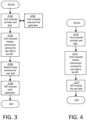
- FIG. 4 is a flowchart illustrating an exemplary method implemented in a communication system, such as, for example, the communication system of FIG. 1 , in accordance with one embodiment.
- the communication system may include a host computer 24, a network node 16 and a WD 22, which may be those described with reference to FIGS. 1 and 2 .
- the host computer 24 provides user data (Block S110).
- the host computer 24 provides the user data by executing a host application, such as, for example, the host application 50.
- the host computer 24 initiates a transmission carrying the user data to the WD 22 (Block 5112).
- the transmission may pass via the network node 16, in accordance with the teachings of the embodiments described throughout this disclosure.
- the WD 22 receives the user data carried in the transmission (Block S 114).
- FIG. 5 is a flowchart illustrating an exemplary method implemented in a communication system, such as, for example, the communication system of FIG. 1 , in accordance with one embodiment.
- the communication system may include a host computer 24, a network node 16 and a WD 22, which may be those described with reference to FIGS. 1 and 2 .
- the WD 22 receives input data provided by the host computer 24 (Block S1 16).
- the WD 22 executes the client application 92, which provides the user data in reaction to the received input data provided by the host computer 24 (Block S 118).
- the WD 22 provides user data (Block S120).
- the WD provides the user data by executing a client application, such as, for example, client application 92 (Block S 122).
- client application 92 may further consider user input received from the user.
- the WD 22 may initiate, in an optional third substep, transmission of the user data to the host computer 24 (Block S124).
- the host computer 24 receives the user data transmitted from the WD 22, in accordance with the teachings of the embodiments described throughout this disclosure (Block S126).
- FIG. 6 is a flowchart illustrating an exemplary method implemented in a communication system, such as, for example, the communication system of FIG. 1 , in accordance with one embodiment.
- the communication system may include a host computer 24, a network node 16 and a WD 22, which may be those described with reference to FIGS. 1 and 2 .
- the network node 16 receives user data from the WD 22 (Block S128).
- the network node 16 initiates transmission of the received user data to the host computer 24 (Block S 130).
- the host computer 24 receives the user data carried in the transmission initiated by the network node 16 (Block S132).
- FIG. 7 is a flowchart of an exemplary process in a network node 16 for providing for an energy detection indicator according to some embodiments of this disclosure.
- One or more Blocks and/or functions performed by network node 16 may be performed by one or more elements of network node 16 such as by the energy detection unit 32 in processing circuitry 68, processor 70, radio interface 62, etc.
- the example process includes performing (Block 134), such as for example via the energy detection unit 32, processing circuitry 68, processor 70, communication interface 60 and/or radio interface 62, energy detection on assigned resources corresponding to a configured uplink grant for a wireless device 22.
- the process includes, based on a level of the detected energy, one of: sending (Block S 136), such as for example via the energy detection unit 32, processing circuitry 68, processor 70, communication interface 60 and/or radio interface 62, an energy detection indication corresponding to the assigned resources associated with the configured uplink grant; and demodulating and decoding, such as via the energy detection unit 32, processing circuitry 68, processor 70, communication interface 60 and/or radio interface 62, a transport block associated with the configured uplink grant.
- sending Block S 136
- demodulating and decoding such as via the energy detection unit 32, processing circuitry 68, processor 70, communication interface 60 and/or radio interface 62, a transport block associated with the configured uplink grant.
- the method further includes if the transport block is correctly decoded, using an implicit hybrid automatic repeat request, HARQ, acknowledgement, ACK, scheme; and if the transport block is not correctly decoded, sending a dynamic grant for retransmission.
- the dynamic grant for retransmission indicates to the wireless device a hybrid automatic repeat request, HARQ, non-acknowledgement, NACK, for the transport block.
- one of sending the energy detection indication and demodulating and decoding the transport block further including: if the level of the detected energy is less than a predefined threshold, sending, such as via the energy detection unit 32, processing circuitry 68, processor 70, communication interface 60 and/or radio interface 62, the energy detection indication corresponding to the assigned resources associated with the configured uplink grant; and if the level of the detected energy is at least equal to the predefined threshold, demodulating and decoding, such as via the energy detection unit 32, processing circuitry 68, processor 70, communication interface 60 and/or radio interface 62, the transport block associated with the configured uplink grant.
- the method further includes, as a result of sending the energy detection indication before a timer expires, receiving, such as via the energy detection unit 32, processing circuitry 68, processor 70, communication interface 60 and/or radio interface 62, a retransmission of the transport block from the WD 22.
- the energy detection indication indicates to the WD 22 whether to retransmit data in a buffer.
- sending the energy detection indication further includes sending, such as via the energy detection unit 32, processing circuitry 68, processor 70, communication interface 60 and/or radio interface 62, the energy detection indication in a downlink control information, DCI, message.
- sending the energy detection indication in the DCI message further includes setting, such as via the energy detection unit 32, processing circuitry 68, processor 70, communication interface 60 and/or radio interface 62, at least one DCI field to a special value, the special value representing the energy detection indication.
- sending the energy detection indication further includes sending the energy detection indication in a group common downlink control information, DCI, message.
- the energy detection indication in the group common DCI message includes at least one bitmap indicating energy detection in physical resource block, PRB, groups.
- sending the energy detection indication further includes sending, such as via the energy detection unit 32, processing circuitry 68, processor 70, communication interface 60 and/or radio interface 62, the energy detection indication in a physical downlink shared channel, PDSCH.
- performing the energy detection on the assigned resources corresponding to the configured uplink grant further includes performing, such as via the energy detection unit 32, processing circuitry 68, processor 70, communication interface 60 and/or radio interface 62, a demodulation reference signal, DMRS, sequence detection on the assigned resources corresponding to the configured uplink grant, the DMRS sequence detection assuming that the wireless device has transmitted a physical uplink shared channel and an associated DMRS according to the configured uplink grant.
- DMRS demodulation reference signal
- performing the energy detection on the assigned resources corresponding to the configured uplink grant further includes performing, such as via the energy detection unit 32, processing circuitry 68, processor 70, communication interface 60 and/or radio interface 62, the energy detection on the assigned resources based on a radio frequency signal detected on the assigned resources corresponding to the configured uplink grant.
- the method further includes communicating, such as for example via the energy detection unit 32 and/or the radio interface 62, an indication of a level of the detected energy to the wireless device as part of a HARQ feedback scheme.
- the method further includes at least one of: determining, such as for example via the energy detection unit 32, whether the detected energy is less than or equal to a pre-defined threshold value; determining, such as for example via the energy detection unit 32, whether or not to communicate an indication of a level of the detected energy based on whether the detected energy is less than or equal to the pre-defined threshold value; and determining, such as for example via the energy detection unit 32, whether or not to demodulate and decode an uplink transmission on the assigned resources based on the level of the detected energy.
- the method further includes communicating, such as for example via the energy detection unit 32 and/or the radio interface 62, an indication of a level of the detected energy in a downlink control information (DCI) message.
- the performing the energy detection comprises performing, such as for example via the energy detection unit 32, a demodulation reference signal (DMRS) sequence detection.
- DMRS demodulation reference signal
- FIG. 8 is a flowchart of an exemplary process in a wireless device 22 according to some embodiments of the present disclosure.
- One or more Blocks and/or functions performed by wireless device 22 may be performed by one or more elements of wireless device 22 such as by the retransmission determination unit 34 in processing circuitry 84, processor 86, radio interface 82, etc.
- the example method includes receiving (Block S 13 8), such as for example via radio interface 82, processing circuitry 84, processor 86 and/or retransmission determination unit 34, an energy detection indication corresponding to assigned resources associated with a configured uplink grant.
- the method includes determining (Block S 140), such as for example via the re-transmission determination unit 34, processing circuitry 84, processor 86 and/or radio interface 82, whether to perform an uplink (UL) re-transmission based at least in part on the energy detection indication.
- the method further includes determining, such as for example via the retransmission determination unit 34, processing circuitry 84, processor 86 and/or radio interface 82, whether data was transmitted in the assigned resources associated with the configured uplink grant, the uplink retransmission being conditioned on the data being transmitted in the assigned resources associated with the configured uplink grant.
- the energy detection indication indicates a level of energy detected on the assigned resources associated with the configured uplink grant relative to a predefined threshold.
- the method further includes if a dynamic grant for retransmission on resources associated with the configured uplink grant is received, retransmit on the resources based on the dynamic grant.
- the dynamic grant for retransmission indicates to the wireless device 22 a hybrid automatic repeat request, HARQ, non-acknowledgement, NACK.
- determining whether to perform the uplink retransmission based at least in part on the received energy detection indication further includes if the energy detection indication is received before a timer expires, assuming, such as for example via the re-transmission determination unit 34, processing circuitry 84, processor 86 and/or radio interface 82, hybrid automatic repeat request, HARQ, non-acknowledgement, NACK and performing the uplink retransmission.
- the energy detection indication indicates to the WD 22 whether to retransmit data in a buffer.
- receiving the energy detection indication further includes receiving, such as for example via the re-transmission determination unit 34, processing circuitry 84, processor 86 and/or radio interface 82, the energy detection indication in a downlink control information, DCI, message.
- receiving the energy detection indication in the DCI message further includes receiving, such as for example via the re-transmission determination unit 34, processing circuitry 84, processor 86 and/or radio interface 82, at least one DCI field that is set to a special value, the special value representing the energy detection indication.
- receiving the energy detection indication further includes receiving, such as for example via the re-transmission determination unit 34, processing circuitry 84, processor 86 and/or radio interface 82, the energy detection indication in a group common downlink control information, DCI, message.
- the energy detection indication in the group common DCI message includes at least one bitmap indicating energy detection in physical resource block, PRB, groups.
- receiving the energy detection indication further includes receiving, such as for example via the re-transmission determination unit 34, processing circuitry 84, processor 86 and/or radio interface 82, the energy detection indication in a physical downlink shared channel, PDSCH.
- the energy detection indication indicates a level of energy detected by a network node on the assigned resources as part of a HARQ feedback scheme.
- the energy detection indication is received in a downlink control information (DCI) message.
- the method further includes performing, such as via the re-transmission determination unit 34, the UL re-transmission based on whether the energy detection indication indicates an energy level that is less than a pre-defined threshold value.
- DCI downlink control information
- the network node 16 may receive data over a physical uplink shared channel (PUSCH) according to the RRC configuration.
- PUSCH physical uplink shared channel
- the network node 16 perform an energy detection process (in addition to the network node's 16 typical activities of decoding data in the PUSCH) over the assigned time-frequency resources for the WD's 22 configured grants.
- FIG. 9 illustrates a schematic of an example energy detection scheme for an uplink grant-free transmission.
- the energy detector unit 32 in the network node 16 examines whether the energy level over the assigned resources is smaller than a pre-defined threshold value.
- the network node 16 may assume Case 2 (e.g., WD 22 sent UL transmission on the assigned resources unsuccessfully). Thus, the network node 16 can send an energy level feedback to the WD 22 indicating e.g., the detected energy level. Otherwise (e.g., if the detected energy level meets or exceeds the pre-defined threshold value), the network node 16 may not send the energy feedback signal to the WD 22.
- Case 2 e.g., WD 22 sent UL transmission on the assigned resources unsuccessfully.
- the network node 16 can send an energy level feedback to the WD 22 indicating e.g., the detected energy level. Otherwise (e.g., if the detected energy level meets or exceeds the pre-defined threshold value), the network node 16 may not send the energy feedback signal to the WD 22.
- a timer may be defined for the energy level feedback.
- the energy level feedback is required to be sent to the WD 22 before such timer expires. If no energy level feedback is sent to WD 22 before the timer expires, the WD 22 may assume Case 1 (e.g., network node 16 received and decoded uplink transmission successfully); thus an implicit ACK scheme can be used and the WD 22 can flush its buffer for the corresponding transport block. In some embodiments, if an energy level feedback is received by the WD 22 before the timer expires, the WD 22 may assume Case 2 and retransmit the UL transmission.
- FIG. 10 illustrates an example of the WD 22 receiving the feedback (e.g., energy detection indication) from the network node 16 as a result of the detected energy being lower than the threshold.
- the WD 22 since the WD 22 may know whether or not, in the previous transmission occasion, the WD 22 sent UL data, the WD 22 can interpret the received energy detector indicator as HARQ NACK or a normal incident.
- FIG. 11 illustrates an example flowchart of a WD 22 decision-making process based on the received signals from the network node 16. As shown in FIG. 11 , there may be data in the WD 22 buffer (Block S150). The WD 22 may determine whether data was transmitted on the previous configured grant (Block S152).
- the WD 22 may determine whether the energy detector signal is less than (or at most meets) a threshold (Block S156). If yes, the WD 22 may consider it a NACK and arrange for re-transmission of the contents of the buffer (Block S158). If no (e.g., the energy detector signal is more than (or at least meets) a threshold, the WD 22 may continue operation based on the current specification (e.g., in some embodiments, this may include flushing the buffer when the timer expires as described in the introduction section).
- the energy detection may be based on baseband signals and using a demodulation reference signal (DMRS) sequence detection. That is, the network node 16 may perform DMRS sequence detection assuming the WD 22 has transmitted PUSCH and associated DMRS according to its UL configured grant configuration. In another embodiment, the energy detection can be based on a radio frequency (RF) signal.
- DMRS demodulation reference signal
- the energy-detection indicator is sent in a group-common DCI to the WD 22.
- the energy-detection indicator is a bitmap of Physical Resource Block (PRB) groups.
- the PRBs may be divided into resource block groups (RBGs).
- RBG resource block groups
- an RBG may include a pair of adjacent PRBs, and the PRBs may be grouped into pairs of PRBs such as (PRB0, PRB1), (PRB2, PRB3), (PRB4, PRB5), (PRB6, PRB7), etc.
- the network node 16 may transmit a bitmap or a sequence of bits (e.g., 0011000).
- the group-common DCI may include and/or indicate, implicitly or explicitly, a time reference back in time relative to the time of reception of the group-common DCI.
- a first configured grant may use PRB2-PRB3 in a first part of a slot; while a second configured grant may also use PRB2-PRB3, but in a second part of a slot.
- the group-common DCI may comprise a first and second bitmap referencing a first and second part of a slot, respectively.
- the network node 16 may perform PUSCH detection according to each individual WD's 22 UL configured grant configuration, including cg-DMRS-Configuration, resourceAllocation, repK, periodicity, etc.
- a WD 22 with an active UL configured grant may be denoted WD_A.
- the network node 16 may then perform energy detection according to the UL configured grant configuration of WD_A, for example, by sequence detection of DMRS according WD_A's cg-DMRS-Configuration, frequencyHopping, repK, etc.
- the energy detection may be performed for each occasion that the WD-A may transmit a TB associated with the CG.
- the energy detection may be performed before the network node 16 performs demodulation and decoding of a potential TB carried by the PUSCH associated with the UL configured grant.
- the WD-A may transmit a TB associated with the CG,
- how to set the value of threshold_A for WD_A may be determined by the network node 16 implementation.
- the threshold A can be set considering the specific configuration of WD_A, for example, the DMRS configuration, antenna port configuration, PUSCH power control configuration of WD_A, etc.
- the threshold_A can be the same as threshold_B of a different WD 22, WD_B, for example, when WD_A and WD_B have similar configurations.
- the threshold_A can be different from threshold_B WD_B, for example, when WD_A and WD_B have different DMRS configuration.
- the energy level feedback can be signaled (e.g., by network node 16) by setting fields of DCI format 0_0 to special values.
- the following setting of special fields may provide for the energy_detection indicator as follows, in Table 1: Table 1. DCI format for energy level feedback.
- DCI format 0_0 Comment New data indicator Set to '0' This differentiates from activation/release DCI of Type 2 CG, which sets "new data indicator” to '1' Frequency domain resource assignment set to all '1's Release DCI of Type 2 CG also sets "Frequency domain resource assignment" to all '1's Time domain resource assignment set to '1111' This differentiates from activation/release DCI of Type 2 CG, which does not set “Time domain resource assignment” to special values Redundancy version set to '11' This differentiates from activation/release DCI of Type 2 CG, which sets "redundancy version” to '00' Modulation and coding scheme set to all '1's Release DCI of Type 2 CG also sets "Modulation and coding scheme" to all '1's
- HARQ process number field in DCI is shown set to the actual HARQ process number of the associated TB.
- the WD 22 may be allowed to start PUSCH transmission at multiple slots for e.g., 3GPP Rel-15 (and possibly mini-slots for future releases).
- the network node 16 may in some embodiments transmit only one energy_detection_indicator for each period, when the network node 16 has decided that WD 22 didn't transmit TB for the entire set of repK slots (or mini-slots).
- the indicator may be deactivated or may be sent in a less frequent manner.
- the indicator may be sent only periodically with possibly a larger period than the configured grant UL period.
- the indication may be deactivated when a condition is met, e.g., when a number of consecutive indication transmissions exceeds a certain threshold.
- the indication may be reactivated following certain condition, e.g.,
- the usage of indication may be according to the indication state (e.g., activated or deactivated) configured in e.g., RRC. If the indication is set to activated, the techniques in this disclosure for energy detection feedback may be used; otherwise if deactivated no energy detection indication may be used.
- the indication state e.g., activated or deactivated
- RRC Radio Resource Control
- comparison operations for a threshold or threshold value may be indicated such as greater than, or less than, or equal to. It should be understood that different types of operations can be used in other embodiments to implement the techniques in this disclosure. For example, where one embodiment may include performing a particular action if a detected level is less than a threshold, another embodiment may include performing the particular action if a detected level is less than or equal to the threshold. Any such comparison operators may be used. Furthermore, in some embodiments, there may be more than one threshold, such as for example, a hierarchy of threshold levels, such as a first threshold level where one type of indicator is sent in one message and, for example, another threshold level that can be used to trigger yet another type of indicator or another type of message or even addition information in the message to be sent.
- the concepts described herein may be embodied as a method, data processing system, computer program product and/or computer storage media storing an executable computer program. Accordingly, the concepts described herein may take the form of an entirely hardware embodiment, an entirely software embodiment or an embodiment combining software and hardware aspects all generally referred to herein as a "circuit" or “module.” Any process, step, action and/or functionality described herein may be performed by, and/or associated to, a corresponding module, which may be implemented in software and/or firmware and/or hardware. Furthermore, the disclosure may take the form of a computer program product on a tangible computer usable storage medium having computer program code embodied in the medium that can be executed by a computer. Any suitable tangible computer readable medium may be utilized including hard disks, CD-ROMs, electronic storage devices, optical storage devices, or magnetic storage devices.
- These computer program instructions may also be stored in a computer readable memory or storage medium that can direct a computer or other programmable data processing apparatus to function in a particular manner, such that the instructions stored in the computer readable memory produce an article of manufacture including instruction means which implement the function/act specified in the flowchart and/or block diagram block or blocks.
- the computer program instructions may also be loaded onto a computer or other programmable data processing apparatus to cause a series of operational steps to be performed on the computer or other programmable apparatus to produce a computer implemented process such that the instructions which execute on the computer or other programmable apparatus provide steps for implementing the functions/acts specified in the flowchart and/or block diagram block or blocks.
- Computer program code for carrying out operations of the concepts described herein may be written in an object oriented programming language such as Java ® or C++.
- the computer program code for carrying out operations of the disclosure may also be written in conventional procedural programming languages, such as the "C" programming language.
- the program code may execute entirely on the user's computer, partly on the user's computer, as a stand-alone software package, partly on the user's computer and partly on a remote computer or entirely on the remote computer.
- the remote computer may be connected to the user's computer through a local area network (LAN) or a wide area network (WAN), or the connection may be made to an external computer (for example, through the Internet using an Internet Service Provider).
- LAN local area network
- WAN wide area network
- Internet Service Provider for example, AT&T, MCI, Sprint, EarthLink, MSN, GTE, etc.
Landscapes
- Engineering & Computer Science (AREA)
- Computer Networks & Wireless Communication (AREA)
- Signal Processing (AREA)
- Quality & Reliability (AREA)
- Physics & Mathematics (AREA)
- Electromagnetism (AREA)
- Mobile Radio Communication Systems (AREA)
Claims (11)
- Verfahren, das in einem Netzwerkknoten (16) implementiert wird, wobei das Verfahren umfasst:
Durchführen (S134) von Energiedetektion an zugeordneten Ressourcen, die einer konfigurierten Uplink-Freigabe für eine drahtlose Vorrichtung, WD, (22) entsprechen, wobei das Durchführen der Energiedetektion an den zugeordneten Ressourcen, die der konfigurierten Uplink-Freigabe entsprechen, ferner eines von Folgendem umfasst:Durchführen einer Demodulationsreferenzsignalfolgedetektion, DMRS-Folgedetektion, an den zugeordneten Ressourcen, die der konfigurierten Uplink-Freigabe entsprechen, wobei die DMRS-Folgedetektion voraussetzt, dass die drahtlose Vorrichtung einen Transportblock auf einem gemeinsamen physikalischen Uplink-Kanal und einem assoziierten DMRS gemäß der konfigurierten Uplink-Freigabe gesendet hat; undDurchführen der Energiedetektion an den zugeordneten Ressourcen, die der konfigurierten Uplink-Freigabe entsprechen, auf einem gemeinsamen physikalischen Uplink-Kanal, auf dem von der drahtlosen Vorrichtung ein Transportblock gesendet wird, basierend auf einem Hochfrequenzsignal, das auf den zugeordneten Ressourcen, die der konfigurierten Uplink-Freigabe entsprechen, detektiert wird; und basierend auf einem Niveau der detektierten Energie eines von Folgendem:wenn das Niveau der detektierten Energie unter einem Schwellenwert liegt, Senden (S136) einer Energiedetektionsanzeige, die den zugeordneten Ressourcen entspricht, die mit der konfigurierten Uplink-Freigabe assoziiert sind, wobei als Ergebnis des Sendens der Energiedetektionsanzeige, bevor ein Zeitgeber abläuft, der gestartet wurde, als der Transportblock auf dem gemeinsamen physikalischen Uplink-Kanal gesendet wurde, eine Neuübertragung des Transportblocks von der WD (22) empfangen wird; undwenn das Niveau der detektierten Energie zumindest gleich dem Schwellenwert ist, Demodulieren und Decodieren des mit der konfigurierten Uplink-Freigabe assoziierten Transportblocks,wobei der Schwellenwert unter Berücksichtigung der spezifischen Konfiguration der WD (22) eingestellt wird, wobei die Konfiguration eine oder mehrere von folgenden umfasst: eine DMRS-Konfiguration, eine Antennenanschlusskonfiguration, eine PUSCH-Leistungssteuerungskonfiguration der WD (22). - Verfahren nach Anspruch 1, ferner umfassend:wenn der Transportblock korrekt decodiert wird, Verwenden eines Schemas einer impliziten Bestätigung, ACK, einer hybriden automatischen Wiederholungsanforderung, HARQ; und,wenn der Transportblock nicht korrekt decodiert wird, Senden einer dynamischen Freigabe für Neuübertragung, wobei die dynamische Freigabe für Neuübertragung der drahtlosen Vorrichtung (22) eine Negativbestätigung, NACK, einer hybriden automatischen Wiederholungsanforderung, HARQ, für den Transportblock anzeigt.
- Verfahren nach einem der Ansprüche 1 bis 3, wobei das Senden der Energiedetektionsanzeige ferner umfasst:
Senden der Energiedetektionsanzeige in einer Downlink-Steuerinformationsnachricht, DCI-Nachricht. - Verfahren, das in einer drahtlosen Vorrichtung, WD, (22) implementiert wird, wobei das Verfahren umfasst:Senden eines Transportblocks auf einem gemeinsamen physikalischen Uplink-Kanal, PUSCH, zusammen mit einem assoziierten Demodulationsreferenzsignal, DMRS, gemäß einer konfigurierten Uplink-Freigabe;Empfangen (S138) einer Energiedetektionsanzeige von einem Netzwerkknoten, die zugeordneten Ressourcen entspricht, die mit der konfigurierten Uplink-Freigabe assoziiert sind, wenn das Niveau der Energie, die durch den Netzwerkknoten an den zugeordneten Ressourcen detektiert wird, die der konfigurierten Freigabe entsprechen, unter einem Schwellenwert liegt, wobei der Schwellenwert am Netzwerkknoten unter Berücksichtigung der spezifischen Konfiguration der WD eingestellt wird, wobei die Konfiguration eine oder mehrere von einer DMRS-Konfiguration, einer Antennenanschlusskonfiguration und einer PUSCH-Leistungssteuerungskonfiguration der WD umfasst;wobei das Verfahren ferner umfasst:
Bestimmen (S140) zumindest teilweise basierend auf der empfangenen Energiedetektionsanzeige, ob eine Uplink-Neuübertragung durchgeführt werden soll, wobei das Bestimmen zumindest teilweise basierend auf der empfangenen Energiedetektionsanzeige, ob eine Uplink-Neuübertragung durchgeführt werden soll, ferner umfasst:wenn die Energiedetektionsanzeige empfangen wird, bevor ein Zeitgeber abläuft, der gestartet wurde, als der Transportblock auf dem gemeinsamen physikalischen Uplink-Kanal gesendet wurde, Voraussetzen einer Negativbestätigung, NACK, einer hybriden automatischen Wiederholungsanforderung, HARQ, und Durchführen der Uplink-Neuübertragung des Transportblocks; und,wenn keine Energiedetektionsanzeige empfangen wird, bevor der Zeitgeber abläuft, Voraussetzen einer impliziten HARQ-Bestätigung, ACK. - Verfahren nach Anspruch 4, ferner umfassend:
Bestimmen (S152), ob Daten in den zugeordneten Ressourcen gesendet wurden, die mit der konfigurierten Uplink-Freigabe assoziiert sind, wobei die Uplink-Neuübertragung davon abhängig gemacht wird, dass die Daten in den zugeordneten Ressourcen gesendet werden, die mit der konfigurierten Uplink-Freigabe assoziiert sind. - Verfahren nach einem der Ansprüche 4 und 5, wobei die Energiedetektionsanzeige ein Niveau von Energie, die an den zugeordneten Ressourcen detektiert wird, die mit der konfigurierten Uplink-Freigabe assoziiert sind, relativ zu einer vordefinierten Schwelle anzeigt.
- Verfahren nach einem der Ansprüche 4 bis 6, ferner umfassend:
wenn eine dynamische Freigabe für Neuübertragung auf Ressourcen, die mit der konfigurierten Uplink-Freigabe assoziiert sind, empfangen wird, erneutes Senden auf den Ressourcen basierend auf der dynamischen Freigabe. - Verfahren nach einem der Ansprüche 4 bis 7, wobei die Energiedetektionsanzeige der WD (22) anzeigt, ob Daten in einem Puffer erneut gesendet werden.
- Verfahren nach einem der Ansprüche 4 bis 8, wobei das Empfangen der Energiedetektionsanzeige ferner umfasst:
Empfangen der Energiedetektionsanzeige in einer Downlink-Steuerinformationsnachricht, DCI-Nachricht. - Netzwerkknoten (16), umfassend eine Verarbeitungsschaltungsanordnung (68) und einen Speicher, wobei der Netzwerkknoten zum Ausführen des Verfahrens nach Anspruch 1 konfiguriert ist.
- Drahtlose Vorrichtung (22), umfassend eine Verarbeitungsschaltungsanordnung (84) und einen Speicher, wobei die drahtlose Vorrichtung zum Ausführen des Verfahrens nach Anspruch 4 konfiguriert ist.
Applications Claiming Priority (2)
| Application Number | Priority Date | Filing Date | Title |
|---|---|---|---|
| US201862755007P | 2018-11-02 | 2018-11-02 | |
| PCT/SE2019/051095 WO2020091681A1 (en) | 2018-11-02 | 2019-10-31 | Energy detection indicator |
Publications (3)
| Publication Number | Publication Date |
|---|---|
| EP3874640A1 EP3874640A1 (de) | 2021-09-08 |
| EP3874640A4 EP3874640A4 (de) | 2022-07-20 |
| EP3874640B1 true EP3874640B1 (de) | 2024-10-23 |
Family
ID=70464303
Family Applications (1)
| Application Number | Title | Priority Date | Filing Date |
|---|---|---|---|
| EP19880113.6A Active EP3874640B1 (de) | 2018-11-02 | 2019-10-31 | Energiedetektionsanzeiger |
Country Status (3)
| Country | Link |
|---|---|
| US (1) | US20220014283A1 (de) |
| EP (1) | EP3874640B1 (de) |
| WO (1) | WO2020091681A1 (de) |
Families Citing this family (2)
| Publication number | Priority date | Publication date | Assignee | Title |
|---|---|---|---|---|
| WO2020167229A1 (en) | 2019-02-15 | 2020-08-20 | Telefonaktiebolaget Lm Ericsson (Publ) | Reliability enhancement for user equipment with partial repetitions in configured grant |
| CN114710217B (zh) * | 2022-05-12 | 2022-08-19 | 广州世炬网络科技有限公司 | 一种数据传输方法、装置、设备及存储介质 |
Family Cites Families (7)
| Publication number | Priority date | Publication date | Assignee | Title |
|---|---|---|---|---|
| CN102057718B (zh) * | 2008-04-14 | 2014-02-12 | 株式会社Ntt都科摩 | 用户装置及通信控制方法 |
| US9048986B2 (en) * | 2011-08-12 | 2015-06-02 | Qualcomm Incorporated | Mitigation of lost resource allocation synchronization between a user equipment (UE) and an evolved node B (eNodeB) |
| CN105578580B (zh) * | 2014-11-03 | 2021-06-04 | 北京三星通信技术研究有限公司 | 功率控制、上报和上行发送的方法、用户设备和控制节点 |
| US10355830B2 (en) * | 2015-12-07 | 2019-07-16 | Telefonaktiebolaget Lm Ericsson (Publ) | Uplink mac protocol aspects |
| US10687335B2 (en) * | 2016-06-10 | 2020-06-16 | Qualcomm Incorporated | Informing base station regarding user equipment's reception of beam change instruction |
| EP3602889B1 (de) * | 2017-03-24 | 2025-01-29 | Telefonaktiebolaget LM Ericsson (PUBL) | Verfahren zur neuübertragung in der semipersisten planung ohne explizites harq-feedback |
| EP3909162A1 (de) * | 2019-01-11 | 2021-11-17 | Telefonaktiebolaget Lm Ericsson (Publ) | Gemeinsame nack für berechtigungsfreie uplink-übertragungen |
-
2019
- 2019-10-31 EP EP19880113.6A patent/EP3874640B1/de active Active
- 2019-10-31 US US17/288,806 patent/US20220014283A1/en not_active Abandoned
- 2019-10-31 WO PCT/SE2019/051095 patent/WO2020091681A1/en not_active Ceased
Also Published As
| Publication number | Publication date |
|---|---|
| EP3874640A1 (de) | 2021-09-08 |
| US20220014283A1 (en) | 2022-01-13 |
| EP3874640A4 (de) | 2022-07-20 |
| WO2020091681A1 (en) | 2020-05-07 |
Similar Documents
| Publication | Publication Date | Title |
|---|---|---|
| US11742982B2 (en) | Activation and deactivation of semi-persistent CSI reporting | |
| CN113261224B (zh) | 用于单dci多时隙调度的harq处理 | |
| JP6584958B2 (ja) | 端末装置、基地局装置および通信方法 | |
| US20200275413A1 (en) | Method and system for determining configuration profiles for grant free communications | |
| EP3811701B1 (de) | Steuersignalisierung für wiederholten sendevorgang | |
| US12207240B2 (en) | Hybrid automatic repeat request (HARQ) feedback for multiple physical downlink shared channel (PDSCH) with downlink (DL) semi-persistent scheduling | |
| WO2020067967A1 (en) | Frequency hopping for transmission with multiple repetitions | |
| JP2019527987A (ja) | 復号ベースのチャネルビジーレシオの決定を用いたlte−v2vのための輻輳制御 | |
| CN116210281A (zh) | 用于自适应地请求按需系统信息的技术 | |
| EP4014404B1 (de) | Übertragung von uplink-steuerungsinformationen mit kollidierendem pusch | |
| US20240305417A1 (en) | Hybrid automatic repeat request (harq) feedback en-/disabling for multicast | |
| US12063676B2 (en) | Inter-modulation avoidance for transmission on different frequencies | |
| EP3841692B1 (de) | Verbesserungen zur angleichung von begrenzten pufferraten | |
| EP3874640B1 (de) | Energiedetektionsanzeiger | |
| WO2022216212A1 (en) | Signaling paging early indicators (pei) with additional information | |
| EP3874653B1 (de) | Erweiterte überwachung eines physikalischen downlink-steuerungskanals | |
| WO2020032852A1 (en) | Beta factors for uplink control information | |
| WO2021069646A1 (en) | Downlink aspects of contention free shared preconfigured uplink resources based on multi user multiple input multiple output | |
| US12557093B2 (en) | Configured grant enhancements in unlicensed band | |
| EP4154455B1 (de) | Konfigurierte gewährungsverbesserungen in einem unlizenzierten band |
Legal Events
| Date | Code | Title | Description |
|---|---|---|---|
| STAA | Information on the status of an ep patent application or granted ep patent |
Free format text: STATUS: THE INTERNATIONAL PUBLICATION HAS BEEN MADE |
|
| PUAI | Public reference made under article 153(3) epc to a published international application that has entered the european phase |
Free format text: ORIGINAL CODE: 0009012 |
|
| STAA | Information on the status of an ep patent application or granted ep patent |
Free format text: STATUS: REQUEST FOR EXAMINATION WAS MADE |
|
| 17P | Request for examination filed |
Effective date: 20210428 |
|
| AK | Designated contracting states |
Kind code of ref document: A1 Designated state(s): AL AT BE BG CH CY CZ DE DK EE ES FI FR GB GR HR HU IE IS IT LI LT LU LV MC MK MT NL NO PL PT RO RS SE SI SK SM TR |
|
| DAV | Request for validation of the european patent (deleted) | ||
| DAX | Request for extension of the european patent (deleted) | ||
| A4 | Supplementary search report drawn up and despatched |
Effective date: 20220617 |
|
| RIC1 | Information provided on ipc code assigned before grant |
Ipc: H04W 72/14 20090101ALI20220611BHEP Ipc: H04L 1/08 20060101ALI20220611BHEP Ipc: H04B 17/309 20150101ALI20220611BHEP Ipc: H04L 1/16 20060101AFI20220611BHEP |
|
| STAA | Information on the status of an ep patent application or granted ep patent |
Free format text: STATUS: EXAMINATION IS IN PROGRESS |
|
| 17Q | First examination report despatched |
Effective date: 20230612 |
|
| REG | Reference to a national code |
Ref country code: DE Ref legal event code: R079 Free format text: PREVIOUS MAIN CLASS: H04L0001160000 Ipc: H04L0001160700 Ref document number: 602019060926 Country of ref document: DE |
|
| RIC1 | Information provided on ipc code assigned before grant |
Ipc: H04B 17/309 20150101ALI20240328BHEP Ipc: H04L 1/08 20060101ALI20240328BHEP Ipc: H04L 1/1607 20230101AFI20240328BHEP |
|
| GRAP | Despatch of communication of intention to grant a patent |
Free format text: ORIGINAL CODE: EPIDOSNIGR1 |
|
| STAA | Information on the status of an ep patent application or granted ep patent |
Free format text: STATUS: GRANT OF PATENT IS INTENDED |
|
| INTG | Intention to grant announced |
Effective date: 20240513 |
|
| GRAS | Grant fee paid |
Free format text: ORIGINAL CODE: EPIDOSNIGR3 |
|
| GRAA | (expected) grant |
Free format text: ORIGINAL CODE: 0009210 |
|
| STAA | Information on the status of an ep patent application or granted ep patent |
Free format text: STATUS: THE PATENT HAS BEEN GRANTED |
|
| AK | Designated contracting states |
Kind code of ref document: B1 Designated state(s): AL AT BE BG CH CY CZ DE DK EE ES FI FR GB GR HR HU IE IS IT LI LT LU LV MC MK MT NL NO PL PT RO RS SE SI SK SM TR |
|
| REG | Reference to a national code |
Ref country code: GB Ref legal event code: FG4D |
|
| REG | Reference to a national code |
Ref country code: CH Ref legal event code: EP |
|
| REG | Reference to a national code |
Ref country code: DE Ref legal event code: R096 Ref document number: 602019060926 Country of ref document: DE |
|
| REG | Reference to a national code |
Ref country code: IE Ref legal event code: FG4D |
|
| REG | Reference to a national code |
Ref country code: LT Ref legal event code: MG9D |
|
| REG | Reference to a national code |
Ref country code: NL Ref legal event code: MP Effective date: 20241023 |
|
| REG | Reference to a national code |
Ref country code: AT Ref legal event code: MK05 Ref document number: 1735726 Country of ref document: AT Kind code of ref document: T Effective date: 20241023 |
|
| PG25 | Lapsed in a contracting state [announced via postgrant information from national office to epo] |
Ref country code: NL Free format text: LAPSE BECAUSE OF FAILURE TO SUBMIT A TRANSLATION OF THE DESCRIPTION OR TO PAY THE FEE WITHIN THE PRESCRIBED TIME-LIMIT Effective date: 20241023 |
|
| PG25 | Lapsed in a contracting state [announced via postgrant information from national office to epo] |
Ref country code: NL Free format text: LAPSE BECAUSE OF FAILURE TO SUBMIT A TRANSLATION OF THE DESCRIPTION OR TO PAY THE FEE WITHIN THE PRESCRIBED TIME-LIMIT Effective date: 20241023 |
|
| PG25 | Lapsed in a contracting state [announced via postgrant information from national office to epo] |
Ref country code: IS Free format text: LAPSE BECAUSE OF FAILURE TO SUBMIT A TRANSLATION OF THE DESCRIPTION OR TO PAY THE FEE WITHIN THE PRESCRIBED TIME-LIMIT Effective date: 20250223 Ref country code: PT Free format text: LAPSE BECAUSE OF FAILURE TO SUBMIT A TRANSLATION OF THE DESCRIPTION OR TO PAY THE FEE WITHIN THE PRESCRIBED TIME-LIMIT Effective date: 20250224 Ref country code: HR Free format text: LAPSE BECAUSE OF FAILURE TO SUBMIT A TRANSLATION OF THE DESCRIPTION OR TO PAY THE FEE WITHIN THE PRESCRIBED TIME-LIMIT Effective date: 20241023 |
|
| PG25 | Lapsed in a contracting state [announced via postgrant information from national office to epo] |
Ref country code: FI Free format text: LAPSE BECAUSE OF FAILURE TO SUBMIT A TRANSLATION OF THE DESCRIPTION OR TO PAY THE FEE WITHIN THE PRESCRIBED TIME-LIMIT Effective date: 20241023 |
|
| PG25 | Lapsed in a contracting state [announced via postgrant information from national office to epo] |
Ref country code: BG Free format text: LAPSE BECAUSE OF FAILURE TO SUBMIT A TRANSLATION OF THE DESCRIPTION OR TO PAY THE FEE WITHIN THE PRESCRIBED TIME-LIMIT Effective date: 20241023 |
|
| PG25 | Lapsed in a contracting state [announced via postgrant information from national office to epo] |
Ref country code: ES Free format text: LAPSE BECAUSE OF FAILURE TO SUBMIT A TRANSLATION OF THE DESCRIPTION OR TO PAY THE FEE WITHIN THE PRESCRIBED TIME-LIMIT Effective date: 20241023 |
|
| PG25 | Lapsed in a contracting state [announced via postgrant information from national office to epo] |
Ref country code: NO Free format text: LAPSE BECAUSE OF FAILURE TO SUBMIT A TRANSLATION OF THE DESCRIPTION OR TO PAY THE FEE WITHIN THE PRESCRIBED TIME-LIMIT Effective date: 20250123 |
|
| PG25 | Lapsed in a contracting state [announced via postgrant information from national office to epo] |
Ref country code: AT Free format text: LAPSE BECAUSE OF FAILURE TO SUBMIT A TRANSLATION OF THE DESCRIPTION OR TO PAY THE FEE WITHIN THE PRESCRIBED TIME-LIMIT Effective date: 20241023 Ref country code: LV Free format text: LAPSE BECAUSE OF FAILURE TO SUBMIT A TRANSLATION OF THE DESCRIPTION OR TO PAY THE FEE WITHIN THE PRESCRIBED TIME-LIMIT Effective date: 20241023 Ref country code: GR Free format text: LAPSE BECAUSE OF FAILURE TO SUBMIT A TRANSLATION OF THE DESCRIPTION OR TO PAY THE FEE WITHIN THE PRESCRIBED TIME-LIMIT Effective date: 20250124 |
|
| PG25 | Lapsed in a contracting state [announced via postgrant information from national office to epo] |
Ref country code: PL Free format text: LAPSE BECAUSE OF FAILURE TO SUBMIT A TRANSLATION OF THE DESCRIPTION OR TO PAY THE FEE WITHIN THE PRESCRIBED TIME-LIMIT Effective date: 20241023 |
|
| PG25 | Lapsed in a contracting state [announced via postgrant information from national office to epo] |
Ref country code: RS Free format text: LAPSE BECAUSE OF FAILURE TO SUBMIT A TRANSLATION OF THE DESCRIPTION OR TO PAY THE FEE WITHIN THE PRESCRIBED TIME-LIMIT Effective date: 20250123 |
|
| REG | Reference to a national code |
Ref country code: DE Ref legal event code: R119 Ref document number: 602019060926 Country of ref document: DE |
|
| REG | Reference to a national code |
Ref country code: CH Ref legal event code: PL |
|
| PG25 | Lapsed in a contracting state [announced via postgrant information from national office to epo] |
Ref country code: SM Free format text: LAPSE BECAUSE OF FAILURE TO SUBMIT A TRANSLATION OF THE DESCRIPTION OR TO PAY THE FEE WITHIN THE PRESCRIBED TIME-LIMIT Effective date: 20241023 |
|
| PG25 | Lapsed in a contracting state [announced via postgrant information from national office to epo] |
Ref country code: MC Free format text: LAPSE BECAUSE OF FAILURE TO SUBMIT A TRANSLATION OF THE DESCRIPTION OR TO PAY THE FEE WITHIN THE PRESCRIBED TIME-LIMIT Effective date: 20241023 |
|
| PG25 | Lapsed in a contracting state [announced via postgrant information from national office to epo] |
Ref country code: DE Free format text: LAPSE BECAUSE OF NON-PAYMENT OF DUE FEES Effective date: 20250501 |
|
| PG25 | Lapsed in a contracting state [announced via postgrant information from national office to epo] |
Ref country code: DK Free format text: LAPSE BECAUSE OF FAILURE TO SUBMIT A TRANSLATION OF THE DESCRIPTION OR TO PAY THE FEE WITHIN THE PRESCRIBED TIME-LIMIT Effective date: 20241023 |
|
| PG25 | Lapsed in a contracting state [announced via postgrant information from national office to epo] |
Ref country code: LU Free format text: LAPSE BECAUSE OF NON-PAYMENT OF DUE FEES Effective date: 20241031 Ref country code: BE Free format text: LAPSE BECAUSE OF NON-PAYMENT OF DUE FEES Effective date: 20241031 |
|
| PG25 | Lapsed in a contracting state [announced via postgrant information from national office to epo] |
Ref country code: EE Free format text: LAPSE BECAUSE OF FAILURE TO SUBMIT A TRANSLATION OF THE DESCRIPTION OR TO PAY THE FEE WITHIN THE PRESCRIBED TIME-LIMIT Effective date: 20241023 |
|
| PG25 | Lapsed in a contracting state [announced via postgrant information from national office to epo] |
Ref country code: CH Free format text: LAPSE BECAUSE OF NON-PAYMENT OF DUE FEES Effective date: 20241031 |
|
| PG25 | Lapsed in a contracting state [announced via postgrant information from national office to epo] |
Ref country code: RO Free format text: LAPSE BECAUSE OF FAILURE TO SUBMIT A TRANSLATION OF THE DESCRIPTION OR TO PAY THE FEE WITHIN THE PRESCRIBED TIME-LIMIT Effective date: 20241023 |
|
| PG25 | Lapsed in a contracting state [announced via postgrant information from national office to epo] |
Ref country code: SK Free format text: LAPSE BECAUSE OF FAILURE TO SUBMIT A TRANSLATION OF THE DESCRIPTION OR TO PAY THE FEE WITHIN THE PRESCRIBED TIME-LIMIT Effective date: 20241023 |
|
| PG25 | Lapsed in a contracting state [announced via postgrant information from national office to epo] |
Ref country code: CZ Free format text: LAPSE BECAUSE OF FAILURE TO SUBMIT A TRANSLATION OF THE DESCRIPTION OR TO PAY THE FEE WITHIN THE PRESCRIBED TIME-LIMIT Effective date: 20241023 |
|
| PG25 | Lapsed in a contracting state [announced via postgrant information from national office to epo] |
Ref country code: IT Free format text: LAPSE BECAUSE OF FAILURE TO SUBMIT A TRANSLATION OF THE DESCRIPTION OR TO PAY THE FEE WITHIN THE PRESCRIBED TIME-LIMIT Effective date: 20241023 |
|
| REG | Reference to a national code |
Ref country code: BE Ref legal event code: MM Effective date: 20241031 |
|
| PLBE | No opposition filed within time limit |
Free format text: ORIGINAL CODE: 0009261 |
|
| STAA | Information on the status of an ep patent application or granted ep patent |
Free format text: STATUS: NO OPPOSITION FILED WITHIN TIME LIMIT |
|
| PG25 | Lapsed in a contracting state [announced via postgrant information from national office to epo] |
Ref country code: SE Free format text: LAPSE BECAUSE OF FAILURE TO SUBMIT A TRANSLATION OF THE DESCRIPTION OR TO PAY THE FEE WITHIN THE PRESCRIBED TIME-LIMIT Effective date: 20241023 |
|
| 26N | No opposition filed |
Effective date: 20250724 |
|
| PG25 | Lapsed in a contracting state [announced via postgrant information from national office to epo] |
Ref country code: FR Free format text: LAPSE BECAUSE OF NON-PAYMENT OF DUE FEES Effective date: 20241223 |
|
| PG25 | Lapsed in a contracting state [announced via postgrant information from national office to epo] |
Ref country code: IE Free format text: LAPSE BECAUSE OF NON-PAYMENT OF DUE FEES Effective date: 20241031 |
|
| PGFP | Annual fee paid to national office [announced via postgrant information from national office to epo] |
Ref country code: GB Payment date: 20251027 Year of fee payment: 7 |