EP3994380B1 - Magnetventil - Google Patents
Magnetventil Download PDFInfo
- Publication number
- EP3994380B1 EP3994380B1 EP20740229.8A EP20740229A EP3994380B1 EP 3994380 B1 EP3994380 B1 EP 3994380B1 EP 20740229 A EP20740229 A EP 20740229A EP 3994380 B1 EP3994380 B1 EP 3994380B1
- Authority
- EP
- European Patent Office
- Prior art keywords
- housing body
- solenoid valve
- coil
- metal yoke
- additives
- Prior art date
- Legal status (The legal status is an assumption and is not a legal conclusion. Google has not performed a legal analysis and makes no representation as to the accuracy of the status listed.)
- Active
Links
Images

Classifications
-
- F—MECHANICAL ENGINEERING; LIGHTING; HEATING; WEAPONS; BLASTING
- F16—ENGINEERING ELEMENTS AND UNITS; GENERAL MEASURES FOR PRODUCING AND MAINTAINING EFFECTIVE FUNCTIONING OF MACHINES OR INSTALLATIONS; THERMAL INSULATION IN GENERAL
- F16K—VALVES; TAPS; COCKS; ACTUATING-FLOATS; DEVICES FOR VENTING OR AERATING
- F16K31/00—Actuating devices; Operating means; Releasing devices
- F16K31/02—Actuating devices; Operating means; Releasing devices electric; magnetic
- F16K31/06—Actuating devices; Operating means; Releasing devices electric; magnetic using a magnet, e.g. diaphragm valves, cutting off by means of a liquid
- F16K31/0675—Electromagnet aspects, e.g. electric supply therefor
-
- F—MECHANICAL ENGINEERING; LIGHTING; HEATING; WEAPONS; BLASTING
- F16—ENGINEERING ELEMENTS AND UNITS; GENERAL MEASURES FOR PRODUCING AND MAINTAINING EFFECTIVE FUNCTIONING OF MACHINES OR INSTALLATIONS; THERMAL INSULATION IN GENERAL
- F16K—VALVES; TAPS; COCKS; ACTUATING-FLOATS; DEVICES FOR VENTING OR AERATING
- F16K27/00—Construction of housing; Use of materials therefor
- F16K27/02—Construction of housing; Use of materials therefor of lift valves
- F16K27/029—Electromagnetically actuated valves
-
- F—MECHANICAL ENGINEERING; LIGHTING; HEATING; WEAPONS; BLASTING
- F16—ENGINEERING ELEMENTS AND UNITS; GENERAL MEASURES FOR PRODUCING AND MAINTAINING EFFECTIVE FUNCTIONING OF MACHINES OR INSTALLATIONS; THERMAL INSULATION IN GENERAL
- F16K—VALVES; TAPS; COCKS; ACTUATING-FLOATS; DEVICES FOR VENTING OR AERATING
- F16K31/00—Actuating devices; Operating means; Releasing devices
- F16K31/02—Actuating devices; Operating means; Releasing devices electric; magnetic
- F16K31/06—Actuating devices; Operating means; Releasing devices electric; magnetic using a magnet, e.g. diaphragm valves, cutting off by means of a liquid
- F16K31/0644—One-way valve
- F16K31/0655—Lift valves
-
- F—MECHANICAL ENGINEERING; LIGHTING; HEATING; WEAPONS; BLASTING
- F16—ENGINEERING ELEMENTS AND UNITS; GENERAL MEASURES FOR PRODUCING AND MAINTAINING EFFECTIVE FUNCTIONING OF MACHINES OR INSTALLATIONS; THERMAL INSULATION IN GENERAL
- F16K—VALVES; TAPS; COCKS; ACTUATING-FLOATS; DEVICES FOR VENTING OR AERATING
- F16K31/00—Actuating devices; Operating means; Releasing devices
- F16K31/02—Actuating devices; Operating means; Releasing devices electric; magnetic
- F16K31/06—Actuating devices; Operating means; Releasing devices electric; magnetic using a magnet, e.g. diaphragm valves, cutting off by means of a liquid
- F16K31/0686—Braking, pressure equilibration, shock absorbing
- F16K31/0696—Shock absorbing, e.g. using a dash-pot
Definitions
- the invention relates to a solenoid valve.
- Solenoid valves known in the prior art have a coil with an armature means mounted within the coil so as to be axially movable against a spring load, a metal yoke enclosing the coil and a housing surrounding the arrangement.
- the housing serves to electrically insulate and protect the magnet arrangement from external influences and is made of an electrically non-conductive material, for example a plastic.
- Such solenoid valves known in the prior art are used, for example, as electrically operated precursors for pneumatic directional valves (“pilot solenoid valve"), with the armature means being designed, for example, with sealing means for a corresponding sealing seat for a gaseous or liquid fluid or acting on a separate actuating element with a sealing means to which it is physically or functionally connected.
- a housing for electromagnets used to actuate valves consisting of a coil and a laminated core surrounding it, which is made of a cast resin (duroplast) and is provided with cooling fins on its outside in order to significantly increase the heat-dissipating surface.
- a cast resin duroplast
- the production of a valve housing with a resin in a casting process is relatively time-consuming.
- Typical cast resins also have a relatively brittle material properties after they have hardened, which means that they are subject to relatively strong material aging due to the intended heat input.
- the adhesive connection of the cast resin at the flat interfaces to the laminated core surrounding the coil can also lead to stress-related cracks in the cast resin body due to the different thermal expansion coefficients of the two materials.
- a housing for a solenoid valve equipped with a valve body in cartridge design which consists of an injection-molded part made of synthetic resin, which encloses the valve construction and which can be designed with a rib-like structure on its outside.
- a solenoid coil is carried in a coil body, which is fastened in a tubular frame, which is encapsulated in an outer body made of a suitable synthetic resin.
- Conventional synthetic resins have only limited thermal conductivity, which means that the achievable heat dissipation via the surface of the synthetic resin housing is correspondingly limited.
- the injection-molded connection of the synthetic resin housing to the tubular frame of the coil body is usually also adhesive at the flat interfaces, which can lead to stress-related cracks in the synthetic resin body due to the different thermal expansion coefficients of the synthetic resin and the frame.
- a valve device with an electrically actuated solenoid valve serving as a pilot valve which has a valve housing in which a solenoid coil is arranged and which has an outer surface facing the environment, on which several cooling fins separated from one another by gaps are provided at least in the area of the solenoid coil, the gaps provided between the cooling fins being open at the ends.
- the cooling fins serve to increase the air gaps available for the air flow and thus to improve heat dissipation by convection.
- the housing section designed with cooling fins can be designed as a plastic part. Conventional plastics have only limited thermal conductivity, which means that the achievable heat dissipation via the surface of the plastic housing is correspondingly limited.
- Technical methods for producing or connecting the plastic part of the valve housing to the solenoid coil are determined by the EP 0 615 088 B1 not disclosed.
- the invention is based on the object of avoiding the disadvantages described.
- a solenoid valve is to be provided which has effective heat dissipation to the surrounding atmosphere and which enables the realization of relatively small solenoid valves with simultaneously relatively high switching and closing forces.
- the core of the invention is a solenoid valve which comprises a housing body made of a thermoplastic material, a coil and a metal yoke which at least partially surrounds the coil, wherein the housing body is designed as an injection-molded part which surrounds the coil, electrically insulating additives are added to the thermoplastic material to improve its thermal conductivity and the housing body is designed with ribs on its outside and wherein the metal yoke is designed as a component which partially surrounds the housing body and is mechanically connected to it.
- the housing body made of a thermoplastic material body is made of a metal yoke which is designed as an injection-molded part which surrounds the coil, electrically insulating additives are added to the thermoplastic material to improve its thermal conductivity and the housing body is designed with ribs on its outside and wherein the metal yoke is designed as a component which partially surrounds the housing body and is mechanically connected to it. Additives with increased thermal conductivity and the simultaneous formation of ribs on the outside of the housing body that increase the surface area for heat dissipation to the surrounding atmosphere ensure effective heat dissipation.
- This enables the realization of relatively small solenoid valves with a relatively high electrical output, which in turn enables relatively high switching and closing forces to be achieved.
- the solenoid valve is structurally simple and inexpensive to manufacture. Since the metal yoke does not directly surround the coil, but is designed as a component that partially surrounds the housing body from the outside and is only mechanically connected to the housing body, stress-related cracks in the housing body due to different thermal expansion coefficients of the two components are avoided at the same time.
- the metal yoke has no adhesive connection to the plastic housing body at its flat interfaces. Due to the purely mechanical connection between the metal yoke arranged on the outside and the housing body directly enclosing the coil, minimal heat-related relative movements between the metal yoke and the housing body are possible. On the interfaces between the plastic housing body and the coil, however, there are no comparable stress moments because the coil has no comparable flat interfaces to the injection-molded part enclosing it on its outside formed by the coil winding.
- the invention provides a solenoid valve with an increased installable power with the same spatial dimensions.
- the metal yoke surrounds the housing body in a U-shape or as a longitudinally cut, partially hollow cylinder.
- the metal yoke is mechanically connected to the housing body by at least one screw connection formed between the flanks or legs enclosing the housing body.
- Mineral and/or inorganic solids are particularly easy to process additives.
- Solid additives with good properties that are particularly inexpensive and available on the market are boron nitrite and/or aluminum oxide.
- Coils for solenoid valves are usually made of an inner carrier element and an outer coil winding, for example made of copper.
- the carrier element is also made of a plastic with increased thermal conductivity due to electrically insulating additives, additionally improved heat dissipation via the carrier element is ensured at the same time.
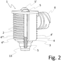
- the Fig.1 and the Fig.2 show the solenoid valve 1 in a perspective front and rear view.
- the solenoid valve 1 has a housing body 2 made of a thermoplastic material and a metal yoke 3 partially enclosing the housing body 2.
- the housing body 2 is formed on its outside with a rib structure that increases the surface for convective heat dissipation to the surrounding atmosphere, of which in the Fig. 1 to Fig. 3 to maintain the For clarity, only the individual ribs 4, 4', 4" and 4′′′ are provided with reference symbols as examples.
- the metal yoke 3 is connected to the housing body 2 in a force-locking manner by the screws 5 and 5'.
- the housing body 2 is formed on its front side with the hollow cylindrical connection base 6 in which electrical contact pins 7 and 7' are arranged.
- the connection base 6 serves to accommodate a plug connection means corresponding to this for establishing an electrical connection of the coil to a power supply.
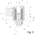
- the Fig.3 shows a schematic longitudinal section through the solenoid valve 1.
- the coil winding 9 is carried on the coil carrier 8.
- the tubular magnet armature 10 is guided axially within the guide sleeve 11 within a central cylindrical recess in the coil carrier 8. When the coil is electrically actuated, the magnet armature 10 moves upwards against the force of the spring 12, whereby a fluid connection can be released in the pneumatic valve part 13.
- the housing body 2 is made of a thermoplastic material and is designed as an injection-molded part that directly encloses the coil.
- the coil is directly overmolded with the thermoplastic material and the housing body 2 is thus molded directly onto the coil in one piece.
- This method of production ensures particularly good heat conduction between the coil and the housing body 2, since an optimal form fit without gaps is created between the thermoplastic material of the housing body 2.
- electrically insulating additives are added to the thermoplastic material, which at the same time have a significantly higher thermal conductivity than the plastic, which improves the dissipation of heat from the coil winding 9 via the housing body 2 to the surrounding atmosphere.
- the solenoid valve 1 enables the installation of a relatively higher output with the same size compared to the designs known in the prior art.
Landscapes
- Engineering & Computer Science (AREA)
- General Engineering & Computer Science (AREA)
- Mechanical Engineering (AREA)
- Physics & Mathematics (AREA)
- Electromagnetism (AREA)
- Magnetically Actuated Valves (AREA)
- Electromagnets (AREA)
Description
- Die Erfindung betrifft ein Magnetventil.
- Im Stand der Technik bekannte Magnetventile weisen eine Spule mit einem innerhalb der Spule axialbeweglich gegen eine Federbelastung gelagerten Ankermittel, ein die Spule umgreifendes Metalljoch und ein die Anordnung umgebendes Gehäuse auf. Das Gehäuse dient der elektrischen Isolierung und dem Schutz der Magnetanordnung vor äußeren Einwirkungen und ist hierzu aus einem elektrisch nicht-leitfähigen Material, beispielsweise einem Kunststoff, gebildet. Derartige im Stand der Technik bekannte Magnetventile finden beispielsweise als elektrische betätigte Vorstufen für pneumatische Wegeventile Anwendung ("Pilot-Magnetventil"), wobei das Ankermittel beispielsweise mit Dichtmitteln für einen korrespondierenden Dichtsitz für ein gasförmiges oder flüssiges Fluid ausgebildet ist oder auf ein separates Stellelement mit einem Dichtmittel einwirkt, mit dem es körperlich oder funktional verbunden ist.
- Es bestehen Marktanforderungen, solche Magnetventile möglichst kleinbauend mit einem gleichzeitig möglichst hohen Durchfluss auszubilden. Hierbei besteht ein Zielkonflikt zwischen benötigten relativ hohen Schalt- und Schließkräften einerseits und den hieraus resultierenden relativ hohen Temperaturen andererseits, die sich aufgrund der geforderten Schalt- und Schließkräfte infolge des Wärmeeintrags durch die hierfür erforderliche elektrische Leistung in der Spulenwicklung bei einer verhältnismäßig kleinen Bauform betriebsbedingt ergeben. Die maximal installierbare elektrische Leistung ist durch die maximal zulässige Temperatur begrenzt, die sich beim Betrieb im Gleichgewichtszustand zwischen dem Wärmeeintrag aufgrund der elektrischen Leistung und der Wärmeableitung über die Spulenoberfläche und Gehäuseoberfläche des Magnetventils an die umgebende Atmosphäre einstellt. Aus den genannten Gründen ist eine möglichst effektive Wärmeableitung über die Oberfläche des elektrisch isolierenden Gehäuses des Magnetventils an die umgebende Atmosphäre wünschenswert.
- Aus der
DE 1 797 854 U ist ein Gehäuse für der Betätigung von Ventilen dienende Elektromagneten, bestehend aus einer Spule und einem diese umgebenden Blechpaket bekannt, welches aus einem Gießharz (Duroplast) gefertigt und auf seiner Außenseite mit Kühlrippen versehen ist, um die wärmeabführende Oberfläche wesentlich zu vergrößern. Zur Verbesserung der Wärmeableitung wird ferner vorgeschlagen, dem Gießharz wärmeleitende Füllstoffe beizugeben. Die Herstellung eines Ventilgehäuses mit einem Harz in einem Gussprozess ist verhältnismäßig zeitaufwendig. Typische Gießharze weisen nach Ihrer Aushärtung ferner eine relativ spröde Materialbeschaffenheit auf, wodurch diese aufgrund des bestimmungsgemäßen Wärmeeintrags einer verhältnismäßig starken Materialalterung unterliegen. Die adhäsive Verbindung des Gießharzes an den ebenen Grenzflächen zu dem die Spule umgebenden Blechpaket kann hierbei zudem aufgrund der unterschiedlichen Wärmeausdehnungskoeffizienten der beiden Materialien zur spannungsbedingten Rissbildungen im Gießharzkörper führen. - Aus der
DE 33 22 844 A1 ist ein Gehäuse für ein mit einem Ventilkörper ausgerüsteten Solenoid-Ventil in Patronenbauweise bekannt, das aus einem Spritzguss-Formteil aus Kunstharz besteht, welches die Ventilkonstruktion einschließt und das auf seiner Außenseite mit einer rippenähnlichen Struktur ausgeführt sein kann. Hierbei ist eine Solenoid-Spule in einem Spulenkörper getragen, der in einem rohrförmigen Rahmen befestigt ist, welcher in einem aus einem geeigneten Kunstharz gebildeten Außenkörper eingekapselt ist. Herkömmliche Kunstharze weisen eine nur begrenzte Wärmeleitfähigkeit auf, wodurch die erreichbare Wärmeableitung über die Oberfläche des Kunstharzgehäuses entsprechend begrenzt ist. Ferner ist die Spritzguss-Verbindung des Kunstharzgehäuses mit dem rohrförmigen Rahmen des Spulenkörpers an den ebenen Grenzflächen üblicherweise auch adhäsiv, wodurch aufgrund der unterschiedlichen Wärmeausdehnungskoeffizienten des Kunstharzes und des Rahmens spannungsbedingte Rissbildungen im Kunstharzkörper entstehen können. - Aus der
EP 0 615 088 B1 ist eine Ventileinrichtung mit einem elektrisch betätigbaren - als Vorsteuerventil dienenden - Magnetventil bekannt, das ein Ventilgehäuse aufweist, in dem eine Magnetspule angeordnet ist, und das eine der Umgebung zugewandte Außenfläche besitzt, an der zumindest im Bereich der Magnetspule mehrere durch Zwischenräume voneinander getrennte Kühlrippen vorgesehen sind, wobei die zwischen den Kühlrippen vorgesehenen Zwischenräume endseitig offen sind. Die Kühlrippen dienen der Vergrößerung der für die Luftströmung zur Verfügung stehenden Luftspalte und damit zu einer verbesserten Wärmeabfuhr durch Konvektion. Der mit Kühlrippen ausgestaltete Gehäuseabschnitt kann als Kunststoffteil ausgeführt sein. Herkömmliche Kunststoffe weisen eine nur begrenzte Wärmeleitfähigkeit auf, wodurch die erreichbare Wärmeableitung über die Oberfläche des Kunststoffgehäuses entsprechend begrenzt ist. Technische Wege zur Herstellung oder Verbindung des Kunststoffteils des Ventilgehäuses mit der Magnetspule sind von derEP 0 615 088 B1 nicht offenbart. - Weitere für den Gegenstand von Anspruch 1 relevante Dokumente sind
US 6 073 904 A ,US 5 710 475 A undUS 4 240 468 A . - Der Erfindung liegt die Aufgabe zu Grunde, die dargestellten Nachteile zu vermeiden. Insbesondere soll ein Magnetventil bereitgestellt werden, welches eine effektive Wärmeableitung an die umgebende Atmosphäre aufweist und welches die Realisierung verhältnismäßig kleinbauender Magnetventile mit gleichzeitig verhältnismäßig hohen Schalt- und Schließkräften ermöglicht.
- Die Aufgabe wird erfindungsgemäß gelöst durch ein Magnetventil nach Anspruch 1. Vorteilhafte Weiterbildungen der Erfindung sind in den Unteransprüchen angegeben.
- Der Kern der Erfindung bildet ein Magnetventil, welches einen aus einem thermoplastischen Kunststoff gebildeten Gehäusekörper, einer Spule und ein die Spule zumindest teilweise umgreifendes Metalljoch umfasst, wobei der Gehäusekörper als ein die Spule umschließendes Spritzgussteil ausgeführt ist, dem thermoplastischen Kunststoff elektrisch isolierende Additive zur Verbesserung seiner thermischen Leitfähigkeit beigegeben sind und der Gehäusekörper auf seiner Außenseite mit Rippen ausgebildet ist und wobei das Metalljoch als ein den Gehäusekörper teilweise umgreifendes Bauteil ausgeführt und mit diesem mechanisch verbunden ist. Mit dem aus einem thermoplastischen Kunststoffkörper gebildeten Gehäusekörper ist durch die Beigabe von Additiven mit einer erhöhten thermischen Leitfähigkeit und die gleichzeitige Ausbildung von die Oberfläche zur Wärmeableitung an die umgebende Atmosphäre vergrößernden Rippen auf der Außenseite des Gehäusekörpers eine effektive Wärmeableitung gewährleistet. Als Additive sind jegliche zur Verarbeitung mit Kunststoff geeigneten Stoffe verwendbar, die eine mit Kunststoffen vergleichbare, nur äußerst geringe elektrische Leitfähigkeit (Isolator) besitzen, gleichzeitig jedoch eine gegenüber dem jeweils verwendeten Kunststoff deutlich erhöhte thermische Leitfähigkeit aufweisen. Dies ermöglicht die Realisierung verhältnismäßig kleinbauender Magnetventile mit einer gleichzeitig relativ hohen elektrischen Leistung, wodurch wiederrum verhältnismäßig hohe Schalt- und Schließkräfte realisierbar sind. Durch die Ausgestaltung des Gehäusekörpers als Spritzgussteil ist das Magnetventil konstruktiv einfach und kostengünstig herstellbar. Indem das Metalljoch nicht unmittelbar die Spule umgreift, sondern als ein den Gehäusekörper von außen teilweise umgreifendes Bauteil ausgeführt ist, welches mit dem Gehäusekörper lediglich mechanisch verbunden ist, werden gleichzeitig spannungsbedingte Risse im Gehäusekörper aufgrund unterschiedlicher Wärmeausdehnungskoeffizienten der beiden Komponenten vermieden. Denn das Metalljoch weist an seinen ebenen Grenzflächen keine adhäsive Verbindung zu dem Kunststoff-Gehäusekörper auf. Aufgrund der rein mechanischen Verbindung zwischen dem außen angeordneten Metalljoch und dem unmittelbar die Spule umschließenden Gehäusekörper sind minimale wärmebedingte Relativbewegungen zwischen dem Metalljoch und den Gehäusekörper ermöglicht. An den Grenzflächen zwischen dem Kunststoff-Gehäusekörper und der Spule sind hingegen keine vergleichbaren Spannungsmomente gegeben, weil die Spule auf ihrer von der Spulenwicklung gebildeten Außenseite keine vergleichbaren ebenen Grenzflächen zu dem ihm umschließenden Spritzgussteil aufweist. Durch die Erfindung wird ein Magnetventil mit einer erhöhten installierbaren Leistung bei gleichbleibender räumlicher Dimensionierung bereitgestellt.
- Ein besonders gute Wärmeleitung zwischen der Spule und dem Gehäusekörper ist gewährleistet, indem der Gehäusekörper als ein einteiliges Bauteil unmittelbar an die Spule angeformt ist. Dies ermöglicht gleichzeitig eine einfache und kostengünstige Herstellung.
- In einer vorteilhaften Ausgestaltung umgreift das Metalljoch den Gehäusekörper U-förmig oder als längsgeschnittener, teilweiser Hohlzylinder.
- Zur konstruktiv einfachen und kostengünstig herstellbaren Ausführung der mechanischen Verbindung ist das Metalljoch mit mindestens einer zwischen den Gehäusekörper umgreifenden Flanken oder Schenkeln gebildeten Schraubverbindung mit diesem mechanisch verbunden.
- Als besonders einfach verarbeitbare Additive sind mineralische und/oder anorganische Feststoffe verwendbar. Im Markt besonders kostengünstig verfügbare Feststoff-Additive mit guten Eigenschaften sind Bornitrit und/oder Aluminiumoxid.
- Spulen für Magnetventile sind in der Regel aus einem inneren Trägerelement und einer äußeren Spulenwicklung, beispielsweise aus Kupfer, gebildet. Indem hierbei auch das Trägerelement aus einem Kunststoff mit durch elektrisch isolierende Additive erhöhten thermischen Leitfähigkeit gebildet ist, ist gleichzeitig eine zusätzlich verbesserte Wärmeableitung über das Trägerelement gewährleistet.
- Indem zwischen dem Gehäusekörper und dem ihn teilweise umgreifenden Metalljoch ein oder mehrere Elastomer-Elemente angeordnet sind, wird eine zusätzlich verbesserte Bewegungsfreiheit zwischen Gehäusekörper und Metalljoch erreicht und mögliche Spannungen im Betrieb weiter reduziert.
- Weitere Vorteile der Erfindung sind nachstehend gemeinsam mit der Beschreibung eines bevorzugten Ausführungsbeispiels der Erfindung anhand der Figuren näher dargestellt. Es zeigen:
- Fig. 1
- eine perspektivische Frontansicht eines Magnetventils.
- Fig. 2
- eine weitere perspektivische Darstellung des Magnetventils gemäß
Fig. 1 . - Fig. 3
- eine schematische Längsschnittdarstellung des Magnetventils gemäß der
Fig. 1 . - Die
Fig. 1 und dieFig. 2 zeigen das Magnetventil 1 in einer perspektivischen Front- und Rückansicht. Das Magnetventil 1 weist einen aus einem thermoplastischen Kunststoff gebildeten Gehäusekörper 2 und ein den Gehäusekörper 2 teilweise umgreifendes Metalljoch 3 auf. Der Gehäusekörper 2 ist auf seiner Außenseite mit einer die Oberfläche zur konvektiven Wärmeableitung an die umgebende Atmosphäre vergrößernden Rippenstruktur ausgebildet, von denen in denFig. 1 bis Fig. 3 zur Beibehaltung der Übersichtlichkeit lediglich die einzelnen Rippen 4, 4', 4" und 4‴ exemplarisch mit Bezugszeichen versehen sind. Das Metalljoch 3 ist mit dem Gehäusekörper 2 kraftschlüssig durch die Schrauben 5 und 5' verbunden. Der Gehäusekörper 2 ist an seiner Frontseite mit dem hohlzylindrischen Anschlusssockel 6 ausgebildet, in dem elektrische Kontaktstifte 7 und 7' angeordnet sind. Der Anschlusssockel 6 dient der Aufnahme eines mit diesem korrespondierenden Steckverbindungsmittels zur Herstellung einer elektrischen Verbindung der Spule mit einer Stromversorgung. DieFig. 3 zeigt einen schematischen Längsschnitt durch das Magnetventil 1. Auf dem Spulenträger 8 ist die Spulenwicklung 9 getragen. Innerhalb einer zentralen zylindrischen Aussparung des Spulenträgers 8 ist der rohrförmige Magnetanker 10 innerhalb der Führungshülse 11 axialbeweglich geführt. Bei der elektrischen Betätigung der Spule bewegt sich der Magnetanker 10 entgegen der Kraft der Feder 12 nach oben, wodurch im pneumatischen Ventilteil 13 eine Fluidverbindung freigebbar ist. Der Gehäusekörper 2 ist aus einem thermoplastischen Kunststoff gebildet und als ein die Spule unmittelbar umschließendes Spritzgussteil ausgeführt. Zur Herstellung des Gehäusekörpers 2 wird die Spule direkt mit dem thermoplastischen Kunststoff umspritzt und der Gehäusekörper 2 mithin unmittelbar einteilig an die Spule angeformt. Auf diese Herstellungsweise ist eine besonders gute Wärmeleitung zwischen der Spule und dem Gehäusekörper 2 gewährleistet, da zwischen dem thermoplastischen Material des Gehäusekörpers 2 ein optimaler Formschluss ohne Spalte hergestellt wird. Dem thermoplastischen Kunststoff sind hierbei zur Verbesserung seiner thermischen Leitfähigkeit elektrisch isolierende Additive mit einer gleichzeitig gegenüber dem Kunststoff deutlich erhöhten thermischen Leitfähigkeit beigegeben, was die Ableitung der Wärme aus der Spulenwicklung 9 über den Gehäusekörper 2 an die an die umgebende Atmosphäre verbessert. Indem das Metalljoch 3 den aus Kunststoff gebildeten Gehäusekörper 2 von außen umgreift und mit diesem lediglich mechanisch kraftschlüssig verbunden ist, sind bei Temperaturänderungen Relativbewegungen zwischen dem Metalljoch 3 und dem Gehäusekörper 2 ermöglicht, wodurch mechanische Beschädigungen des Gehäusekörpers vermieden werden. Das Magnetventil 1 ermöglicht gegenüber den im Stand der Technik bekannten Konstruktionen die Installation einer relativ höheren Leistung bei gleicher Baugröße. -
- 1
- Magnetventil
- 2
- Gehäusekörper
- 3
- Metalljoch
- 4, 4', 4", 4‴
- Rippe
- 5, 5'
- Schraube
- 6
- Anschlusssockel
- 7, 7'
- Kontaktstift
- 8
- Spulenträger
- 9
- Spulenwicklung
- 10
- Magnetanker
- 11
- Führungshülse
- 12
- Feder
- 13
- Ventilteil
Claims (8)
- Magnetventil (1), umfassend einen aus einem thermoplastischen Kunststoff gebildeten Gehäusekörper (2), eine Spule und ein zumindest teilweise um die Spule angeordnetes Metalljoch (3), wobei das Metalljoch (3) als ein den Gehäusekörper (2) teilweise umgreifendes Bauteil ausgeführt und mit diesem mechanisch verbunden ist, und wobei der Gehäusekörper (2) als ein die Spule umschließendes Spritzgussteil ausgeführt ist, dadurch gekennzeichnet, dass dem thermoplastischen Kunststoff elektrisch isolierende Additive zur Erhöhung seiner thermischen Leitfähigkeit beigegeben sind und der Gehäusekörper (2) auf seiner Außenseite mit Rippen ausgebildet ist.
- Magnetventil (1) nach Anspruch 1, dadurch gekennzeichnet, dass der Gehäusekörper (2) als ein einteiliges Bauteil unmittelbar an die Spule angeformt ist.
- Magnetventil : (1) nach Anspruch 1 oder 2, dadurch gekennzeichnet, dass das Metalljoch (3) den Gehäusekörper (2) U-förmig oder als längsgeschnittener, teilweiser Hohlzylinder umgreift.
- Magnetventil (1) nach einem der Ansprüche 1 bis 3, dadurch gekennzeichnet, dass das Metalljoch (3) mit mindestens einer zwischen den Gehäusekörper (2) umgreifenden Flanken oder Schenkeln gebildeten Schraubverbindung mit diesem mechanisch verbunden ist.
- Magnetventil (1) nach einem Ansprüche 1 bis 4, dadurch gekennzeichnet, dass das die Additive mineralische und/oder anorganische Feststoffe sind.
- Magnetventil (1) nach Anspruch 5, dadurch gekennzeichnet, dass die Additive Bornitrit und/oder Aluminiumoxid sind.
- Magnetventil (1) nach einem der Ansprüche 1 bis 6, dadurch gekennzeichnet, dass die Spule ein inneres Trägerelement (8) und eine äußere Spulenwicklung (9) umfasst, wobei das Trägerelement (8) aus einem Kunststoff mit durch elektrisch isolierende Additive erhöhten thermischen Leitfähigkeit gebildet ist.
- Magnetventil (1) nach einem der Ansprüche 1 bis 7, dadurch gekennzeichnet, dass zwischen dem Gehäusekörper (2) und dem ihn teilweise umgreifenden Metalljoch (3) ein oder mehrere Elastomer-Elemente angeordnet sind.
Applications Claiming Priority (2)
| Application Number | Priority Date | Filing Date | Title |
|---|---|---|---|
| DE102019004597.1A DE102019004597A1 (de) | 2019-07-04 | 2019-07-04 | Magnetventil |
| PCT/DE2020/100592 WO2021001000A1 (de) | 2019-07-04 | 2020-07-03 | Magnetventil |
Publications (2)
| Publication Number | Publication Date |
|---|---|
| EP3994380A1 EP3994380A1 (de) | 2022-05-11 |
| EP3994380B1 true EP3994380B1 (de) | 2024-08-28 |
Family
ID=71614661
Family Applications (1)
| Application Number | Title | Priority Date | Filing Date |
|---|---|---|---|
| EP20740229.8A Active EP3994380B1 (de) | 2019-07-04 | 2020-07-03 | Magnetventil |
Country Status (7)
| Country | Link |
|---|---|
| US (1) | US11846362B2 (de) |
| EP (1) | EP3994380B1 (de) |
| JP (1) | JP7490683B2 (de) |
| CN (1) | CN114026355B (de) |
| DE (2) | DE102019004597A1 (de) |
| MX (1) | MX2021015856A (de) |
| WO (1) | WO2021001000A1 (de) |
Families Citing this family (6)
| Publication number | Priority date | Publication date | Assignee | Title |
|---|---|---|---|---|
| DE102021208742A1 (de) * | 2021-08-11 | 2023-02-16 | Robert Bosch Gesellschaft mit beschränkter Haftung | Magnetspule mit Kühlstruktur und Magnetventil mit derartiger Magnetspule |
| CN113611478B (zh) * | 2021-10-08 | 2022-01-25 | 余姚市三力信电磁阀有限公司 | 一种用于电磁阀的电磁线圈结构 |
| CN217081611U (zh) * | 2022-04-18 | 2022-07-29 | 盾安环境技术有限公司 | 电磁阀及其线圈、线圈的外壳 |
| DE102022116095A1 (de) | 2022-06-28 | 2023-12-28 | Sysko AG Systeme & Komponenten | Treiberspulenvorrichtung |
| DE102023101721A1 (de) | 2023-01-24 | 2024-07-25 | Bürkert Werke GmbH & Co. KG | Kühlvorrichtung für ein Spulengehäuse eines Magnetventilantriebs und Einheit mit einem Magnetventilantrieb und einer Kühlvorrichtung |
| CN117869649A (zh) * | 2024-01-10 | 2024-04-12 | 江苏恩迪汽车系统股份有限公司 | 汽车座椅用一体式散热电磁阀阀组及散热方法 |
Family Cites Families (19)
| Publication number | Priority date | Publication date | Assignee | Title |
|---|---|---|---|---|
| DE1797854U (de) * | 1959-05-06 | 1959-10-15 | Hahn Magnet Ing Fred Hahn | Ventilmagnet. |
| US4240468A (en) * | 1977-03-30 | 1980-12-23 | Hauni-Werke Korber & Co. Kg | Solenoid operated valve |
| GB2124034B (en) * | 1982-06-28 | 1986-09-10 | Imp Clevite Inc | Solenoid valve |
| US4526340A (en) * | 1982-06-28 | 1985-07-02 | Imperial Clevite Inc. | Solenoid valve |
| DE3314722C1 (de) * | 1983-04-22 | 1984-06-20 | Danfoss A/S, Nordborg | Magnetventil fuer Kaelteanlagen |
| US5011872A (en) * | 1987-12-21 | 1991-04-30 | The Carborudum Company | Thermally conductive ceramic/polymer composites |
| DE9303660U1 (de) * | 1993-03-12 | 1993-05-06 | Festo KG, 7300 Esslingen | Ventileinrichtung, insbesondere für die Pneumatik |
| US5552222A (en) * | 1995-01-27 | 1996-09-03 | General Electric Company | Electrically conductive articles comprising insulation resistant to corona discharge-induced degradation |
| US5710475A (en) * | 1995-11-22 | 1998-01-20 | General Electric Company | Insulation of high thermal conductivity and apparatus containing same |
| JPH09250650A (ja) * | 1996-03-18 | 1997-09-22 | Aichi Electric Co Ltd | 防湿型電磁弁 |
| US6073904A (en) * | 1997-10-02 | 2000-06-13 | Diller; Ronald G. | Latching coil valve |
| JP3660135B2 (ja) * | 1998-07-30 | 2005-06-15 | 株式会社ケーヒン | バルブの駆動部の固定構造 |
| WO2001066933A1 (en) * | 2000-03-08 | 2001-09-13 | Hitachi, Ltd. | Electromagnetic type fuel injection valve |
| US20040108395A1 (en) * | 2001-09-13 | 2004-06-10 | Hitachi, Ltd. | Electromagnetic fuel injector |
| DE102010042069A1 (de) * | 2010-10-06 | 2012-04-12 | Robert Bosch Gmbh | Verfahren zum Herstellen von Magnetspulen |
| DE102011056853A1 (de) * | 2011-12-22 | 2013-06-27 | Eto Magnetic Gmbh | Spulenträger sowie elektromagnetische Stellvorrichtung mit Spulenträger |
| JP2015008309A (ja) * | 2014-08-08 | 2015-01-15 | 株式会社鷺宮製作所 | モールドコイルおよびモールドコイルを用いた電磁弁 |
| DE102015007694A1 (de) * | 2015-06-17 | 2016-12-22 | Andreas Stihl Ag & Co. Kg | Elektromagnetisches Ventil für ein Kraftstoffsystem |
| CN208967097U (zh) * | 2018-08-24 | 2019-06-11 | 上海侨亨实业有限公司 | 脉冲电磁阀 |
-
2019
- 2019-07-04 DE DE102019004597.1A patent/DE102019004597A1/de not_active Withdrawn
-
2020
- 2020-07-03 US US17/624,623 patent/US11846362B2/en active Active
- 2020-07-03 JP JP2021578129A patent/JP7490683B2/ja active Active
- 2020-07-03 EP EP20740229.8A patent/EP3994380B1/de active Active
- 2020-07-03 CN CN202080048910.0A patent/CN114026355B/zh active Active
- 2020-07-03 WO PCT/DE2020/100592 patent/WO2021001000A1/de not_active Ceased
- 2020-07-03 MX MX2021015856A patent/MX2021015856A/es unknown
- 2020-07-03 DE DE112020003211.6T patent/DE112020003211A5/de not_active Withdrawn
Also Published As
| Publication number | Publication date |
|---|---|
| JP2022538662A (ja) | 2022-09-05 |
| BR112021025785A2 (pt) | 2022-04-12 |
| JP7490683B2 (ja) | 2024-05-27 |
| MX2021015856A (es) | 2022-04-18 |
| DE112020003211A5 (de) | 2022-03-17 |
| DE102019004597A1 (de) | 2021-01-07 |
| CN114026355A (zh) | 2022-02-08 |
| US11846362B2 (en) | 2023-12-19 |
| WO2021001000A1 (de) | 2021-01-07 |
| US20220252175A1 (en) | 2022-08-11 |
| EP3994380A1 (de) | 2022-05-11 |
| CN114026355B (zh) | 2024-09-06 |
Similar Documents
| Publication | Publication Date | Title |
|---|---|---|
| EP3994380A1 (de) | Magnetventil | |
| EP1292994B1 (de) | Piezoaktor | |
| EP0642141B1 (de) | Überspannungsableiter | |
| EP0545038B1 (de) | Überspannungsableiter | |
| DE29712502U1 (de) | Elektromagnetischer Aktuator mit Gehäuse | |
| DE4428869C2 (de) | Magnetventil | |
| DE102014215916A1 (de) | Sensoreinrichtung für einen Elektromotor sowie Elektromotor mit der Sensoreinrichtung | |
| DE102015203435A1 (de) | Temperatursensor, Stator und Verfahren zur Herstellung eines Stators sowie elektrische Maschine mit Temperatursensor und Stator | |
| EP2430756B1 (de) | Sensor | |
| DE102009028501A1 (de) | Kraftstoffzumesseinrichtung für eine Kraftstoffeinspritzanlage | |
| DE102016211536A1 (de) | Elektromotor sowie ein Verfahren zu dessen Herstellung | |
| DE102019217964A1 (de) | Kühlsystem und Bauteil für eine elektrische Maschine mit Hohlleiterkühlung | |
| DE102004060532A1 (de) | Vorrichtung mit Formgedächtniselement | |
| EP1878030B1 (de) | Elektropneumatisches patronenventil, insbesondere zum einsatz als vorsteuerventil bei einem schmalbauenden pneumatikventil für eine kompakte ventileinheit | |
| EP1737715B1 (de) | Magnetventil | |
| EP1394399A1 (de) | Fahrzeug-Elektromagnetventil, insbesondere Abgasrückführventil, und Verfahren zur Herstellung eines Fahrzeug-Elektromagnetventils | |
| EP3993562B1 (de) | Heizpatrone mit keramischer vergussmasse | |
| DE10319632B4 (de) | Pilotmagnetventil | |
| WO2018224376A1 (de) | Elektronisches bauteil und verfahren zu dessen herstellung | |
| EP3446012B1 (de) | Pneumatische mehrventilvorrichtung sowie herstellverfahren | |
| DE102011112755B4 (de) | Elektro-Magnet, Verfahren zur Herstellung eines Elektro-Magneten und dessen Verwendung, Ventil mit einem Elektromagneten und dessen Verwendung sowie Luftfahrzeug | |
| DE102014103245B4 (de) | Elektromagnetventil sowie Pneumatiksystem | |
| DE102015105116B4 (de) | Elektromagnetventil sowie sicherheitsrelevantes Pneumatiksystem mit einem solchen Elektromagnetventil | |
| WO2000070197A1 (de) | Elektromechanischer stellantrieb | |
| DE10310460B3 (de) | Tauchspulenaktor |
Legal Events
| Date | Code | Title | Description |
|---|---|---|---|
| STAA | Information on the status of an ep patent application or granted ep patent |
Free format text: STATUS: UNKNOWN |
|
| STAA | Information on the status of an ep patent application or granted ep patent |
Free format text: STATUS: THE INTERNATIONAL PUBLICATION HAS BEEN MADE |
|
| PUAI | Public reference made under article 153(3) epc to a published international application that has entered the european phase |
Free format text: ORIGINAL CODE: 0009012 |
|
| STAA | Information on the status of an ep patent application or granted ep patent |
Free format text: STATUS: REQUEST FOR EXAMINATION WAS MADE |
|
| 17P | Request for examination filed |
Effective date: 20220131 |
|
| AK | Designated contracting states |
Kind code of ref document: A1 Designated state(s): AL AT BE BG CH CY CZ DE DK EE ES FI FR GB GR HR HU IE IS IT LI LT LU LV MC MK MT NL NO PL PT RO RS SE SI SK SM TR |
|
| DAV | Request for validation of the european patent (deleted) | ||
| DAX | Request for extension of the european patent (deleted) | ||
| P01 | Opt-out of the competence of the unified patent court (upc) registered |
Effective date: 20230529 |
|
| GRAP | Despatch of communication of intention to grant a patent |
Free format text: ORIGINAL CODE: EPIDOSNIGR1 |
|
| STAA | Information on the status of an ep patent application or granted ep patent |
Free format text: STATUS: GRANT OF PATENT IS INTENDED |
|
| INTG | Intention to grant announced |
Effective date: 20240129 |
|
| GRAS | Grant fee paid |
Free format text: ORIGINAL CODE: EPIDOSNIGR3 |
|
| GRAA | (expected) grant |
Free format text: ORIGINAL CODE: 0009210 |
|
| STAA | Information on the status of an ep patent application or granted ep patent |
Free format text: STATUS: THE PATENT HAS BEEN GRANTED |
|
| AK | Designated contracting states |
Kind code of ref document: B1 Designated state(s): AL AT BE BG CH CY CZ DE DK EE ES FI FR GB GR HR HU IE IS IT LI LT LU LV MC MK MT NL NO PL PT RO RS SE SI SK SM TR |
|
| REG | Reference to a national code |
Ref country code: CH Ref legal event code: EP |
|
| REG | Reference to a national code |
Ref country code: DE Ref legal event code: R096 Ref document number: 502020009035 Country of ref document: DE |
|
| REG | Reference to a national code |
Ref country code: IE Ref legal event code: FG4D Free format text: LANGUAGE OF EP DOCUMENT: GERMAN |
|
| REG | Reference to a national code |
Ref country code: NL Ref legal event code: FP |
|
| REG | Reference to a national code |
Ref country code: SE Ref legal event code: TRGR |
|
| REG | Reference to a national code |
Ref country code: LT Ref legal event code: MG9D |
|
| PG25 | Lapsed in a contracting state [announced via postgrant information from national office to epo] |
Ref country code: NO Free format text: LAPSE BECAUSE OF FAILURE TO SUBMIT A TRANSLATION OF THE DESCRIPTION OR TO PAY THE FEE WITHIN THE PRESCRIBED TIME-LIMIT Effective date: 20241128 |
|
| PG25 | Lapsed in a contracting state [announced via postgrant information from national office to epo] |
Ref country code: PT Free format text: LAPSE BECAUSE OF FAILURE TO SUBMIT A TRANSLATION OF THE DESCRIPTION OR TO PAY THE FEE WITHIN THE PRESCRIBED TIME-LIMIT Effective date: 20241230 Ref country code: PL Free format text: LAPSE BECAUSE OF FAILURE TO SUBMIT A TRANSLATION OF THE DESCRIPTION OR TO PAY THE FEE WITHIN THE PRESCRIBED TIME-LIMIT Effective date: 20240828 Ref country code: FI Free format text: LAPSE BECAUSE OF FAILURE TO SUBMIT A TRANSLATION OF THE DESCRIPTION OR TO PAY THE FEE WITHIN THE PRESCRIBED TIME-LIMIT Effective date: 20240828 Ref country code: GR Free format text: LAPSE BECAUSE OF FAILURE TO SUBMIT A TRANSLATION OF THE DESCRIPTION OR TO PAY THE FEE WITHIN THE PRESCRIBED TIME-LIMIT Effective date: 20241129 |
|
| PG25 | Lapsed in a contracting state [announced via postgrant information from national office to epo] |
Ref country code: BG Free format text: LAPSE BECAUSE OF FAILURE TO SUBMIT A TRANSLATION OF THE DESCRIPTION OR TO PAY THE FEE WITHIN THE PRESCRIBED TIME-LIMIT Effective date: 20240828 |
|
| PG25 | Lapsed in a contracting state [announced via postgrant information from national office to epo] |
Ref country code: LV Free format text: LAPSE BECAUSE OF FAILURE TO SUBMIT A TRANSLATION OF THE DESCRIPTION OR TO PAY THE FEE WITHIN THE PRESCRIBED TIME-LIMIT Effective date: 20240828 |
|
| PG25 | Lapsed in a contracting state [announced via postgrant information from national office to epo] |
Ref country code: IS Free format text: LAPSE BECAUSE OF FAILURE TO SUBMIT A TRANSLATION OF THE DESCRIPTION OR TO PAY THE FEE WITHIN THE PRESCRIBED TIME-LIMIT Effective date: 20241228 |
|
| PG25 | Lapsed in a contracting state [announced via postgrant information from national office to epo] |
Ref country code: HR Free format text: LAPSE BECAUSE OF FAILURE TO SUBMIT A TRANSLATION OF THE DESCRIPTION OR TO PAY THE FEE WITHIN THE PRESCRIBED TIME-LIMIT Effective date: 20240828 |
|
| PG25 | Lapsed in a contracting state [announced via postgrant information from national office to epo] |
Ref country code: ES Free format text: LAPSE BECAUSE OF FAILURE TO SUBMIT A TRANSLATION OF THE DESCRIPTION OR TO PAY THE FEE WITHIN THE PRESCRIBED TIME-LIMIT Effective date: 20240828 Ref country code: RS Free format text: LAPSE BECAUSE OF FAILURE TO SUBMIT A TRANSLATION OF THE DESCRIPTION OR TO PAY THE FEE WITHIN THE PRESCRIBED TIME-LIMIT Effective date: 20241128 |
|
| PG25 | Lapsed in a contracting state [announced via postgrant information from national office to epo] |
Ref country code: RS Free format text: LAPSE BECAUSE OF FAILURE TO SUBMIT A TRANSLATION OF THE DESCRIPTION OR TO PAY THE FEE WITHIN THE PRESCRIBED TIME-LIMIT Effective date: 20241128 Ref country code: PT Free format text: LAPSE BECAUSE OF FAILURE TO SUBMIT A TRANSLATION OF THE DESCRIPTION OR TO PAY THE FEE WITHIN THE PRESCRIBED TIME-LIMIT Effective date: 20241230 Ref country code: PL Free format text: LAPSE BECAUSE OF FAILURE TO SUBMIT A TRANSLATION OF THE DESCRIPTION OR TO PAY THE FEE WITHIN THE PRESCRIBED TIME-LIMIT Effective date: 20240828 Ref country code: NO Free format text: LAPSE BECAUSE OF FAILURE TO SUBMIT A TRANSLATION OF THE DESCRIPTION OR TO PAY THE FEE WITHIN THE PRESCRIBED TIME-LIMIT Effective date: 20241128 Ref country code: LV Free format text: LAPSE BECAUSE OF FAILURE TO SUBMIT A TRANSLATION OF THE DESCRIPTION OR TO PAY THE FEE WITHIN THE PRESCRIBED TIME-LIMIT Effective date: 20240828 Ref country code: IS Free format text: LAPSE BECAUSE OF FAILURE TO SUBMIT A TRANSLATION OF THE DESCRIPTION OR TO PAY THE FEE WITHIN THE PRESCRIBED TIME-LIMIT Effective date: 20241228 Ref country code: HR Free format text: LAPSE BECAUSE OF FAILURE TO SUBMIT A TRANSLATION OF THE DESCRIPTION OR TO PAY THE FEE WITHIN THE PRESCRIBED TIME-LIMIT Effective date: 20240828 Ref country code: GR Free format text: LAPSE BECAUSE OF FAILURE TO SUBMIT A TRANSLATION OF THE DESCRIPTION OR TO PAY THE FEE WITHIN THE PRESCRIBED TIME-LIMIT Effective date: 20241129 Ref country code: FI Free format text: LAPSE BECAUSE OF FAILURE TO SUBMIT A TRANSLATION OF THE DESCRIPTION OR TO PAY THE FEE WITHIN THE PRESCRIBED TIME-LIMIT Effective date: 20240828 Ref country code: ES Free format text: LAPSE BECAUSE OF FAILURE TO SUBMIT A TRANSLATION OF THE DESCRIPTION OR TO PAY THE FEE WITHIN THE PRESCRIBED TIME-LIMIT Effective date: 20240828 Ref country code: BG Free format text: LAPSE BECAUSE OF FAILURE TO SUBMIT A TRANSLATION OF THE DESCRIPTION OR TO PAY THE FEE WITHIN THE PRESCRIBED TIME-LIMIT Effective date: 20240828 |
|
| PG25 | Lapsed in a contracting state [announced via postgrant information from national office to epo] |
Ref country code: SM Free format text: LAPSE BECAUSE OF FAILURE TO SUBMIT A TRANSLATION OF THE DESCRIPTION OR TO PAY THE FEE WITHIN THE PRESCRIBED TIME-LIMIT Effective date: 20240828 Ref country code: RO Free format text: LAPSE BECAUSE OF FAILURE TO SUBMIT A TRANSLATION OF THE DESCRIPTION OR TO PAY THE FEE WITHIN THE PRESCRIBED TIME-LIMIT Effective date: 20240828 Ref country code: DK Free format text: LAPSE BECAUSE OF FAILURE TO SUBMIT A TRANSLATION OF THE DESCRIPTION OR TO PAY THE FEE WITHIN THE PRESCRIBED TIME-LIMIT Effective date: 20240828 |
|
| PG25 | Lapsed in a contracting state [announced via postgrant information from national office to epo] |
Ref country code: EE Free format text: LAPSE BECAUSE OF FAILURE TO SUBMIT A TRANSLATION OF THE DESCRIPTION OR TO PAY THE FEE WITHIN THE PRESCRIBED TIME-LIMIT Effective date: 20240828 |
|
| PG25 | Lapsed in a contracting state [announced via postgrant information from national office to epo] |
Ref country code: CZ Free format text: LAPSE BECAUSE OF FAILURE TO SUBMIT A TRANSLATION OF THE DESCRIPTION OR TO PAY THE FEE WITHIN THE PRESCRIBED TIME-LIMIT Effective date: 20240828 |
|
| PG25 | Lapsed in a contracting state [announced via postgrant information from national office to epo] |
Ref country code: SK Free format text: LAPSE BECAUSE OF FAILURE TO SUBMIT A TRANSLATION OF THE DESCRIPTION OR TO PAY THE FEE WITHIN THE PRESCRIBED TIME-LIMIT Effective date: 20240828 |
|
| REG | Reference to a national code |
Ref country code: DE Ref legal event code: R097 Ref document number: 502020009035 Country of ref document: DE |
|
| PLBE | No opposition filed within time limit |
Free format text: ORIGINAL CODE: 0009261 |
|
| STAA | Information on the status of an ep patent application or granted ep patent |
Free format text: STATUS: NO OPPOSITION FILED WITHIN TIME LIMIT |
|
| 26N | No opposition filed |
Effective date: 20250530 |
|
| REG | Reference to a national code |
Ref country code: DE Ref legal event code: R119 Ref document number: 502020009035 Country of ref document: DE |
|
| REG | Reference to a national code |
Ref country code: CH Ref legal event code: H13 Free format text: ST27 STATUS EVENT CODE: U-0-0-H10-H13 (AS PROVIDED BY THE NATIONAL OFFICE) Effective date: 20260224 |
|
| REG | Reference to a national code |
Ref country code: NL Ref legal event code: MM Effective date: 20250801 |
|
| PG25 | Lapsed in a contracting state [announced via postgrant information from national office to epo] |
Ref country code: LU Free format text: LAPSE BECAUSE OF NON-PAYMENT OF DUE FEES Effective date: 20250703 |
|
| GBPC | Gb: european patent ceased through non-payment of renewal fee |
Effective date: 20250703 |
|
| REG | Reference to a national code |
Ref country code: BE Ref legal event code: MM Effective date: 20250731 |
|
| PG25 | Lapsed in a contracting state [announced via postgrant information from national office to epo] |
Ref country code: GB Free format text: LAPSE BECAUSE OF NON-PAYMENT OF DUE FEES Effective date: 20250703 |
|
| PG25 | Lapsed in a contracting state [announced via postgrant information from national office to epo] |
Ref country code: DE Free format text: LAPSE BECAUSE OF NON-PAYMENT OF DUE FEES Effective date: 20260203 |
|
| PG25 | Lapsed in a contracting state [announced via postgrant information from national office to epo] |
Ref country code: BE Free format text: LAPSE BECAUSE OF NON-PAYMENT OF DUE FEES Effective date: 20250731 |
|
| PG25 | Lapsed in a contracting state [announced via postgrant information from national office to epo] |
Ref country code: NL Free format text: LAPSE BECAUSE OF NON-PAYMENT OF DUE FEES Effective date: 20250801 |
|
| PG25 | Lapsed in a contracting state [announced via postgrant information from national office to epo] |
Ref country code: FR Free format text: LAPSE BECAUSE OF NON-PAYMENT OF DUE FEES Effective date: 20250731 |
|
| PG25 | Lapsed in a contracting state [announced via postgrant information from national office to epo] |
Ref country code: CH Free format text: LAPSE BECAUSE OF NON-PAYMENT OF DUE FEES Effective date: 20250731 |