EP3994361B1 - Pumpenanordnung mit temperierbarem gehäuseteil - Google Patents
Pumpenanordnung mit temperierbarem gehäuseteil Download PDFInfo
- Publication number
- EP3994361B1 EP3994361B1 EP20743595.9A EP20743595A EP3994361B1 EP 3994361 B1 EP3994361 B1 EP 3994361B1 EP 20743595 A EP20743595 A EP 20743595A EP 3994361 B1 EP3994361 B1 EP 3994361B1
- Authority
- EP
- European Patent Office
- Prior art keywords
- temperature
- pump arrangement
- wall
- chamber
- collection chamber
- Prior art date
- Legal status (The legal status is an assumption and is not a legal conclusion. Google has not performed a legal analysis and makes no representation as to the accuracy of the status listed.)
- Active
Links
Images


Classifications
-
- B—PERFORMING OPERATIONS; TRANSPORTING
- B22—CASTING; POWDER METALLURGY
- B22F—WORKING METALLIC POWDER; MANUFACTURE OF ARTICLES FROM METALLIC POWDER; MAKING METALLIC POWDER; APPARATUS OR DEVICES SPECIALLY ADAPTED FOR METALLIC POWDER
- B22F10/00—Additive manufacturing of workpieces or articles from metallic powder
- B22F10/20—Direct sintering or melting
- B22F10/25—Direct deposition of metal particles, e.g. direct metal deposition [DMD] or laser engineered net shaping [LENS]
-
- B—PERFORMING OPERATIONS; TRANSPORTING
- B22—CASTING; POWDER METALLURGY
- B22F—WORKING METALLIC POWDER; MANUFACTURE OF ARTICLES FROM METALLIC POWDER; MAKING METALLIC POWDER; APPARATUS OR DEVICES SPECIALLY ADAPTED FOR METALLIC POWDER
- B22F12/00—Apparatus or devices specially adapted for additive manufacturing; Auxiliary means for additive manufacturing; Combinations of additive manufacturing apparatus or devices with other processing apparatus or devices
- B22F12/38—Housings, e.g. machine housings
-
- B—PERFORMING OPERATIONS; TRANSPORTING
- B22—CASTING; POWDER METALLURGY
- B22F—WORKING METALLIC POWDER; MANUFACTURE OF ARTICLES FROM METALLIC POWDER; MAKING METALLIC POWDER; APPARATUS OR DEVICES SPECIALLY ADAPTED FOR METALLIC POWDER
- B22F5/00—Manufacture of workpieces or articles from metallic powder characterised by the special shape of the product
- B22F5/10—Manufacture of workpieces or articles from metallic powder characterised by the special shape of the product of articles with cavities or holes, not otherwise provided for in the preceding subgroups
-
- B—PERFORMING OPERATIONS; TRANSPORTING
- B33—ADDITIVE MANUFACTURING TECHNOLOGY
- B33Y—ADDITIVE MANUFACTURING, i.e. MANUFACTURING OF THREE-DIMENSIONAL [3D] OBJECTS BY ADDITIVE DEPOSITION, ADDITIVE AGGLOMERATION OR ADDITIVE LAYERING, e.g. BY 3D PRINTING, STEREOLITHOGRAPHY OR SELECTIVE LASER SINTERING
- B33Y10/00—Processes of additive manufacturing
-
- F—MECHANICAL ENGINEERING; LIGHTING; HEATING; WEAPONS; BLASTING
- F04—POSITIVE - DISPLACEMENT MACHINES FOR LIQUIDS; PUMPS FOR LIQUIDS OR ELASTIC FLUIDS
- F04D—NON-POSITIVE-DISPLACEMENT PUMPS
- F04D1/00—Radial-flow pumps, e.g. centrifugal pumps; Helico-centrifugal pumps
-
- F—MECHANICAL ENGINEERING; LIGHTING; HEATING; WEAPONS; BLASTING
- F04—POSITIVE - DISPLACEMENT MACHINES FOR LIQUIDS; PUMPS FOR LIQUIDS OR ELASTIC FLUIDS
- F04D—NON-POSITIVE-DISPLACEMENT PUMPS
- F04D15/00—Control, e.g. regulation, of pumps, pumping installations or systems
- F04D15/02—Stopping of pumps, or operating valves, on occurrence of unwanted conditions
- F04D15/0245—Stopping of pumps, or operating valves, on occurrence of unwanted conditions responsive to a condition of the pump
- F04D15/0263—Stopping of pumps, or operating valves, on occurrence of unwanted conditions responsive to a condition of the pump the condition being temperature, ingress of humidity or leakage
-
- F—MECHANICAL ENGINEERING; LIGHTING; HEATING; WEAPONS; BLASTING
- F04—POSITIVE - DISPLACEMENT MACHINES FOR LIQUIDS; PUMPS FOR LIQUIDS OR ELASTIC FLUIDS
- F04D—NON-POSITIVE-DISPLACEMENT PUMPS
- F04D29/00—Details, component parts, or accessories
- F04D29/02—Selection of particular materials
- F04D29/026—Selection of particular materials especially adapted for liquid pumps
-
- F—MECHANICAL ENGINEERING; LIGHTING; HEATING; WEAPONS; BLASTING
- F04—POSITIVE - DISPLACEMENT MACHINES FOR LIQUIDS; PUMPS FOR LIQUIDS OR ELASTIC FLUIDS
- F04D—NON-POSITIVE-DISPLACEMENT PUMPS
- F04D29/00—Details, component parts, or accessories
- F04D29/40—Casings; Connections of working fluid
- F04D29/42—Casings; Connections of working fluid for radial or helico-centrifugal pumps
- F04D29/426—Casings; Connections of working fluid for radial or helico-centrifugal pumps especially adapted for liquid pumps
-
- F—MECHANICAL ENGINEERING; LIGHTING; HEATING; WEAPONS; BLASTING
- F04—POSITIVE - DISPLACEMENT MACHINES FOR LIQUIDS; PUMPS FOR LIQUIDS OR ELASTIC FLUIDS
- F04D—NON-POSITIVE-DISPLACEMENT PUMPS
- F04D29/00—Details, component parts, or accessories
- F04D29/58—Cooling; Heating; Diminishing heat transfer
- F04D29/586—Cooling; Heating; Diminishing heat transfer specially adapted for liquid pumps
-
- F—MECHANICAL ENGINEERING; LIGHTING; HEATING; WEAPONS; BLASTING
- F04—POSITIVE - DISPLACEMENT MACHINES FOR LIQUIDS; PUMPS FOR LIQUIDS OR ELASTIC FLUIDS
- F04D—NON-POSITIVE-DISPLACEMENT PUMPS
- F04D29/00—Details, component parts, or accessories
- F04D29/58—Cooling; Heating; Diminishing heat transfer
- F04D29/586—Cooling; Heating; Diminishing heat transfer specially adapted for liquid pumps
- F04D29/588—Cooling; Heating; Diminishing heat transfer specially adapted for liquid pumps cooling or heating the machine
-
- B—PERFORMING OPERATIONS; TRANSPORTING
- B22—CASTING; POWDER METALLURGY
- B22D—CASTING OF METALS; CASTING OF OTHER SUBSTANCES BY THE SAME PROCESSES OR DEVICES
- B22D25/00—Special casting characterised by the nature of the product
- B22D25/02—Special casting characterised by the nature of the product by its peculiarity of shape; of works of art
-
- B—PERFORMING OPERATIONS; TRANSPORTING
- B22—CASTING; POWDER METALLURGY
- B22F—WORKING METALLIC POWDER; MANUFACTURE OF ARTICLES FROM METALLIC POWDER; MAKING METALLIC POWDER; APPARATUS OR DEVICES SPECIALLY ADAPTED FOR METALLIC POWDER
- B22F10/00—Additive manufacturing of workpieces or articles from metallic powder
- B22F10/20—Direct sintering or melting
- B22F10/28—Powder bed fusion, e.g. selective laser melting [SLM] or electron beam melting [EBM]
-
- B—PERFORMING OPERATIONS; TRANSPORTING
- B22—CASTING; POWDER METALLURGY
- B22F—WORKING METALLIC POWDER; MANUFACTURE OF ARTICLES FROM METALLIC POWDER; MAKING METALLIC POWDER; APPARATUS OR DEVICES SPECIALLY ADAPTED FOR METALLIC POWDER
- B22F12/00—Apparatus or devices specially adapted for additive manufacturing; Auxiliary means for additive manufacturing; Combinations of additive manufacturing apparatus or devices with other processing apparatus or devices
- B22F12/50—Means for feeding of material, e.g. heads
- B22F12/53—Nozzles
-
- B—PERFORMING OPERATIONS; TRANSPORTING
- B33—ADDITIVE MANUFACTURING TECHNOLOGY
- B33Y—ADDITIVE MANUFACTURING, i.e. MANUFACTURING OF THREE-DIMENSIONAL [3D] OBJECTS BY ADDITIVE DEPOSITION, ADDITIVE AGGLOMERATION OR ADDITIVE LAYERING, e.g. BY 3D PRINTING, STEREOLITHOGRAPHY OR SELECTIVE LASER SINTERING
- B33Y80/00—Products made by additive manufacturing
-
- F—MECHANICAL ENGINEERING; LIGHTING; HEATING; WEAPONS; BLASTING
- F05—INDEXING SCHEMES RELATING TO ENGINES OR PUMPS IN VARIOUS SUBCLASSES OF CLASSES F01-F04
- F05D—INDEXING SCHEME FOR ASPECTS RELATING TO NON-POSITIVE-DISPLACEMENT MACHINES OR ENGINES, GAS-TURBINES OR JET-PROPULSION PLANTS
- F05D2230/00—Manufacture
- F05D2230/20—Manufacture essentially without removing material
- F05D2230/21—Manufacture essentially without removing material by casting
- F05D2230/211—Manufacture essentially without removing material by casting by precision casting, e.g. microfusing or investment casting
-
- F—MECHANICAL ENGINEERING; LIGHTING; HEATING; WEAPONS; BLASTING
- F05—INDEXING SCHEMES RELATING TO ENGINES OR PUMPS IN VARIOUS SUBCLASSES OF CLASSES F01-F04
- F05D—INDEXING SCHEME FOR ASPECTS RELATING TO NON-POSITIVE-DISPLACEMENT MACHINES OR ENGINES, GAS-TURBINES OR JET-PROPULSION PLANTS
- F05D2260/00—Function
- F05D2260/30—Retaining components in desired mutual position
- F05D2260/31—Retaining bolts or nuts
-
- Y—GENERAL TAGGING OF NEW TECHNOLOGICAL DEVELOPMENTS; GENERAL TAGGING OF CROSS-SECTIONAL TECHNOLOGIES SPANNING OVER SEVERAL SECTIONS OF THE IPC; TECHNICAL SUBJECTS COVERED BY FORMER USPC CROSS-REFERENCE ART COLLECTIONS [XRACs] AND DIGESTS
- Y02—TECHNOLOGIES OR APPLICATIONS FOR MITIGATION OR ADAPTATION AGAINST CLIMATE CHANGE
- Y02P—CLIMATE CHANGE MITIGATION TECHNOLOGIES IN THE PRODUCTION OR PROCESSING OF GOODS
- Y02P10/00—Technologies related to metal processing
- Y02P10/25—Process efficiency
Definitions
- the invention relates to a pump arrangement according to the preamble of claim 1 and a method according to the preamble of claim 9.
- Such pump arrangements are often used in industrial plants, especially in the chemical and petrochemical industries.
- Media are often pumped or conveyed that can only be conveyed or pumped at a certain temperature.
- One such medium is sulphur. If the temperature drops or rises too much at some points in the pump during the pumping process, the medium can crystallise and cause the pump to run dry. Furthermore, such crystallisation can also contaminate the pumped medium.
- Known heated spiral casings have the disadvantage that they consist of several individual parts, which are usually connected by welding. Leaks can occur at the welds if they are not welded correctly, which significantly impairs the function of the pump.
- the US 2007/0000648 A1 describes a system with a pump for cooling electronic components.
- the US 3 936 220 A discloses a pump for hot and cold media with a jacket structure surrounding the pump through which a temperature control medium flows, which keeps the medium to be pumped at a desired temperature.
- heating the housing cover / spiral casing of the pump is often not sufficient to achieve an optimum temperature for pumping a specific medium.
- sealing covers have the additional disadvantage that they consist of several individual parts, which are usually connected to one another by welding. Leaks can occur at the welds if they are not welded correctly, which further impairs the function of the pump.
- sealing covers With such sealing covers, the additional arrangement of lines that run through a possible cooling/heating chamber arranged in the sealing cover is difficult or not feasible in practice. For example, in order to provide external circulation with a conventional sealing cover, the heating chamber of the sealing cover would have to be drilled through.
- the present invention is based on the object of mitigating or even completely eliminating the deficiencies of the devices known from the prior art. Specifically, it is an object of the present invention to provide a pump arrangement by means of which the conveyance of media at an optimal conveying temperature is ensured.
- the first collection chamber and the second collection chamber are formed in the temperature control chamber.
- the first connection device is provided for a supply line through which the cooling or heating medium flows into the temperature control chamber to control the temperature of the hydraulic housing. Furthermore, the second connection device is provided for connecting a supply line through which the cooling or heating medium flows out of the temperature control chamber.
- the at least one channel or channels have a defined structure which serves to maximize turbulence in the cooling or heating medium and thus to maximize heat exchange.
- the component preferably has a support structure.
- the support structure absorbs the forces and moments that occur, for example, at the suction and pressure ports and dissipates them.
- the component is stiffened with a minimum of dead weight, which, for example, minimizes the risk of the impeller grinding against a split ring that is usually housed in the hydraulic housing or against part of the hydraulic housing.
- the support structure formed on the outer wall by material accumulation thus supports and relieves both the relatively thin inner wall and the relatively thin outer wall of the hydraulic housing.
- the support structure connects defined components of the component to one another, in particular housing feet, suction nozzles, pressure nozzles and connection points to which further components of the pump arrangement can be attached.
- free ends of the support structure have blind holes for receiving suitable fastening means, in particular screws or threaded bolts. Internal threads are advantageously provided into which the fastening means can be screwed.
- a further object of the present invention is to provide a method for producing a hydraulic housing for a pump arrangement as a one-piece component by means of 3D printing, in particular metallic 3D printing, selective laser melting (SLM), or by means of investment casting.
- 3D printing in particular metallic 3D printing, selective laser melting (SLM), or by means of investment casting.
- SLM selective laser melting
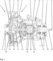
- the Fig. 1 shows a pump arrangement 1 in the form of a magnetic coupling pump arrangement.
- the pump arrangement 1 has a multi-part pump housing 2 of a centrifugal pump, which comprises a temperature-controlled component 3 designed as a hydraulic housing, a housing cover 4, a bearing support lantern 5, a bearing support 6 and a bearing cover 7.
- the component 3 which in the present example is designed as a hydraulic housing, has an inlet opening 9 on a suction nozzle 8 for sucking in a conveying medium and an outlet opening 11 on a pressure nozzle 10 for expelling the conveying medium.
- the housing cover 4 is arranged on the side of the hydraulic housing 3 opposite the inlet opening 9.
- the bearing support lantern 5 is fastened to the side of the housing cover 4 facing away from the hydraulic housing 3.
- the bearing support 6 is attached to the side of the bearing support lantern 5 opposite the housing cover 4.
- the bearing cover 7 is in turn fastened to the side of the bearing support 6 facing away from the bearing support lantern 5.
- a containment shell 12 is attached to the side of the housing cover 4 facing away from the hydraulic housing 3 and extends at least partially through an interior space 13 delimited by the pump housing 2, in particular by the housing cover 4, by the bearing support lantern 5 and by the bearing support 6.
- the containment shell 12 hermetically seals a chamber 14 enclosed by it from the interior space 13.
- An impeller shaft 15 rotatable about a rotation axis A extends from a flow chamber 16 delimited by the hydraulic housing 3 and the housing cover 4 through an opening 17 provided in the housing cover 4 into the chamber 14.
- a bearing arrangement 21 which is operatively connected to the impeller shaft 15 which can be driven to rotate about the axis of rotation A.
- a drive motor (not shown), preferably an electric motor, drives a drive shaft 22.
- the drive shaft 22, which can be driven to rotate about the axis of rotation A, is arranged essentially coaxially with the impeller shaft 15.
- the drive shaft 22 extends through the bearing cover 7 and the bearing carrier 6 and is mounted in two ball bearings 23, 24 accommodated in the bearing carrier 6.
- An outer rotor 26 carrying several magnets 25 is arranged at the free end of the drive shaft 22. The magnets 25 are arranged on the side of the outer rotor 26 facing the containment shell 12.
- the outer rotor 26 extends at least partially over the containment shell 12 and interacts with the inner rotor 19 in such a way that the rotating outer rotor 26 also sets the inner rotor 19 and thus the impeller shaft 15 and the impeller 18 into a rotational movement by means of magnetic forces.
- the Fig. 2 , 3 and 4 show exemplary designs of the hydraulic housing 3 in detail.
- the hydraulic housing 3 has a first wall or inner wall 27 and a second wall or outer wall 28 spaced from the inner wall 27.
- the inner wall 27 and the outer wall 28 form or delimit a temperature control chamber 29.
- the temperature control chamber 29 extends between the inner wall 27 and the outer wall 28 and essentially over the part of the inner wall 27 that delimits the flow chamber 16. That is, from a surface 30 of the hydraulic housing 3, against which the housing cover 4 rests, over the entire hydraulic housing 3 to the suction nozzle 8.
- a plurality of struts 31 are provided in the temperature control chamber 29, which connect the inner wall 27 to the outer wall 28. This creates, as shown schematically in Fig.
- circular channels 32 which are arranged essentially concentrically to the axis of rotation A. If the struts are omitted, a circular channel 32 is created, which in section, as shown in Fig. 4 shown, has a substantially S-shaped course.
- the struts 31 and the channels 32 are not continuous, ie they are interrupted.
- Fig. 5 The web shown in Fig. 1, which extends from the pressure port 10 to the suction port 8 and connects the inner wall 27 and the outer wall 28, forms a partition wall 33 in the temperature control chamber 29.
- the struts 31 do not touch the partition wall 33, so that, as in Fig. 5 shown schematically, a first collecting chamber 34 and a second collecting chamber 35 are formed in the tempering chamber 29.
- the first collecting chamber 34 and the second collecting chamber 35 have a substantially radial extension, starting from an area close to the suction nozzle 8, in particular in the direction of the pressure nozzle 10.
- the struts 31 are also not continuous. This creates a third, in the Fig. 5 schematically shown collecting chamber 36 is formed.
- a first connection device 37 is provided on the pressure port 10, via which a cooling or heating medium can flow into the temperature control chamber 29 for tempering, ie for cooling and/or heating the hydraulic housing 3.
- a second connection device, to which the reference number 38 refers, via which the cooling or heating medium can flow out of the temperature control chamber 29 again, is arranged opposite the first connection device 37.
- the arrangement of the second connection device 38 is best shown in the Fig. 5 recognizable.
- the channel 32 or the channels 32 have a defined structure O, which is used to maximize turbulence in the cooling or heating medium and thus to maximize serve for heat exchange.
- there are channels 32 which are, for example, circular, oval, essentially L- or V-shaped or have depressions.
- the struts 31 can, for example, have a wing-like profile.
- the channel 32 or the channels 32 and the struts 31 can also have bionic structures, for example a sharkskin-like structure.
- the outer wall 28 has a defined surface structure O on the side facing the outside environment, in particular a wave-like surface structure O.
- the hydraulic housing 3 has a fourth connection device 40 which is intended for the complete emptying of the flow chamber 16.
- the connection device 40 is arranged above the connection device 39.
- the connection device 40 is arranged such that the emptying of the flow chamber 16 takes place essentially in the axial direction.
- the cooling or heating medium flows via the first connection device 37 into the first collecting chamber 34 of the temperature control chamber 29 and from there into the individual channels 32 which are directly connected to one another in terms of fluid technology, finally into the second collecting chamber 35 and from there via the second connection device 38 out of the temperature control chamber 29. In this way, a uniform temperature distribution across the hydraulic housing 3 is achieved.
- cooling or heating medium can also be supplied to the temperature control chamber 29 via the second connection device 38 and flows out of the temperature control chamber 29 via the first connection device 37.
- the hydraulic housing 3 also has a support structure 41, which absorbs and dissipates the forces and moments occurring at the suction nozzle 8 and the pressure nozzle 10. In addition, this stiffens the hydraulic housing 3, which reduces the risk of the impeller 18 grinding against a Fig. 1 shown split ring 42 or on a part of the hydraulic housing 3.
- the support structure 41 formed on the outer wall 28 by material accumulation thus supports and relieves both the relatively thin inner wall 27 and the relatively thin outer wall of the hydraulic housing 3.
- the support structure 41 connects defined components of the hydraulic housing to one another, in particular housing feet 43, suction nozzle 8, pressure nozzle 10 and connection points 44 to which further components of the pump arrangement can be fastened, for example the housing cover 4.
- the support structure 41 is designed to be optimized for force flow and topology.
- the support structure 41 essentially has horizontal, vertical and diagonal material accumulations that form node or intersection points 45. Free ends 46 of the support structure 41 have blind holes 47 that are intended to accommodate fastening means (not shown), for example screws or threaded bolts.
- the Fig. 1 shows a pump arrangement 1 in the form of a magnetic coupling pump arrangement.
- the hydraulic housing 3 according to the invention can be used with other pump arrangements, for example canned motor pumps, inline pumps or any pumps without a magnetic coupling.
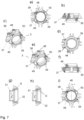
- a non-inventive, temperature-controlled component 3 which in the example shown is designed as a sealing cover, in particular for accommodating a mechanical seal, has a connection device 37 or inlet for cooling / heating medium and a second connection device 38 or outlet for cooling / heating medium.
- the first connection device 37 and the second connection device 38 are arranged opposite one another.
- the temperature control medium is thus guided through the ring-shaped component 3.
- a partition wall (not shown here) can be provided in the temperature control chamber so that a first collection chamber and a second collection chamber are formed in the temperature control chamber.
- the cooling/heating medium circulates in at least one channel 32, which is formed in the interior of the temperature-controlled component 3 and is provided with defined surface structures O to maximize turbulence in the cooling/heating medium and thus to maximize heat exchange.
- the sealing cover 3 has a third connection device 39, which can be used for draining the cooling/heating medium contained therein at the lowest point of the cooling/heating channel 32 or the temperature control chamber not shown in the sealing cover.
- a fifth connection device 48 can be provided for external circulation, which can be led out of the component 3 again via the third connection device.
- the temperature-controlled component 3 1 not according to the invention can also be equipped with a sixth connection device 49 or inlet for quenching medium and a seventh connection device 50 or outlet for quenching medium.
- the housing parts 3 described above for a pump arrangement 1 are advantageously produced as a one-piece component by means of 3D printing, in particular metallic 3D printing, selective laser melting (SLM), or by means of investment casting.
- 3D printing in particular metallic 3D printing, selective laser melting (SLM), or by means of investment casting.
- SLM selective laser melting
Landscapes
- Engineering & Computer Science (AREA)
- Mechanical Engineering (AREA)
- Manufacturing & Machinery (AREA)
- Chemical & Material Sciences (AREA)
- Materials Engineering (AREA)
- General Engineering & Computer Science (AREA)
- Physics & Mathematics (AREA)
- Thermal Sciences (AREA)
- Structures Of Non-Positive Displacement Pumps (AREA)
- Details Of Reciprocating Pumps (AREA)
- Details And Applications Of Rotary Liquid Pumps (AREA)
Description
- Die Erfindung betrifft eine Pumpenanordnung gemäß des Oberberiffs des Anspruchs 1 und ein Verfahren gemäß des Oberbegriffs des Anspruchs 9.
- Derartige Pumpenanordnungen werden oftmals in Industrieanlagen, insbesondere in der Chemie und Petrochemie, eingesetzt. Dabei werden häufig Medien gepumpt bzw. gefördert, welche nur bei einer bestimmten Temperatur förderbar bzw. pumpbar sind.
- Ein derartiges Medium ist beispielsweise Schwefel. Sinkt oder steigt die Temperatur während des Pumpprozesses an einigen Stellen in der Pumpe zu stark, kann das Medium auskristallisieren und somit einen Trockenlauf der Pumpe verursachen. Weiterhin kann ein derartiges Auskristallisieren auch das Fördermedium verunreinigen.
- Ein weiteres Beispiel ist die Förderung von Schweröl oder Bitumen. Zur Förderung dieser Medien müssen die eingesetzten Pumpen beispielsweise bei sehr tiefen Temperaturen vorgeheizt werden, um ein Trockenlaufen der Pumpe zu vermeiden, da Schweröl und Bitumen ohne eine vorherige Erwärmung zu viskos sind, um pumpbar zu sein. Unter anderem bei Prozesspumpen ist eine genaue Regulierung der Temperatur von entscheidender Bedeutung, da schwankende Temperaturen einen gesamten Anlagenprozess stören können.
- Bekannte beheizbare Spiralgehäuse haben den Nachteil, dass sie aus mehreren Einzelteilen bestehen, welche meist durch Schweißen miteinander verbunden werden. An den Schweißstellen kann es zu Leckagen kommen, wenn diese nicht korrekt verschweißt sind, was die Funktion der Pumpe wesentlich verschlechtert.
- Zudem gestaltet es sich bei derartigen Schweißkonstruktionen schwierig, das komplette Gehäuse inklusive der Flansche gleichmäßig zu temperieren.
- In der
WO 2016/116428 A1 wird eine Pumpe beschrieben, deren Gehäuse zur Beheizung einen Hohlraum aufweist, der von einem Temperiermedium durchströmt wird. - Die
US 2007/0000648 A1 beschreibt ein System mit einer Pumpe zur Kühlung von elektronischen Komponenten. - Aus der
FR 2 008 305 A1 - Die
US 3 936 220 A offenbart eine Pumpe für heiße und kalte Medien mit einer die Pumpe umgebenden Mantelkonstruktion durch die ein Temperatursteuermedium strömt, das das zu fördernde Medium auf eine gewünschte Temperatur hält. - Aus der
US 2006/171801 A1 ist eine Kühlkörpervorrichtung mit einem Kühler und einer Kreiselpumpe bekannt, wobei die Kreiselpumpe Wärme von der wärmeerzeugenden Komponente abführt. - Bei herkömmlichen Pumpen können die an den Stutzen bzw. Einlass- und Auslassöffnungen anliegenden Kräfte und Momente das Gehäuse verformen und zu einem Anlaufen des Laufrads an angrenzende Bauteile der Pumpe führen.
- Auch der Punkt im Prozessfluss / der Ort an der Pumpe, an dem eine Gleitringdichtung meist angeordnet ist, insbesondere der Bereich zwischen der Welle und dem Gehäusedeckel einer Pumpe, hat sich in der Praxis als ein kritischer Bereich erwiesen, in dem es relativ häufig zu Problemen bezüglich der Bereitstellung der erforderlichen Temperatur kommt.
- Die Beheizung des Gehäusedeckels / Spiralgehäuses der Pumpe reicht an diesem Punkt häufig nicht aus, um eine optimale Temperatur zur Förderung eines bestimmten Mediums zu erreichen.
- Zudem haben konventionelle Dichtungsdeckel den zusätzlichen Nachteil, dass sie aus mehreren Einzelteilen bestehen, welche meist durch Schweißen miteinander verbunden sind. An den Schweißstellen kann es zu Leckagen kommen, wenn diese nicht korrekt verschweißt sind, was die Funktion der Pumpe weiter verschlechtert.
- Zudem gestaltet sich bei derartigen Dichtungsdeckeln das zusätzliche Anordnen von Leitungen, welche durch eine etwaige in dem Dichtungsdeckel angeordnete Kühl-I Heizkammer verlaufen, schwierig bzw. ist in der Praxis nicht realisierbar. Beispielsweise müsste zur Bereitstellung einer externen Zirkulation bei einem herkömmlichen Dichtungsdeckel der Heizraum des Dichtungsdeckels durchgebohrt werden.
- Der vorliegenden Erfindung liegt die Aufgabe zugrunde, die Mängel der aus dem Stand der Technik bekannten Vorrichtungen abzumildern oder gar ganz zu beheben. Konkret ist es eine Aufgabe der vorliegenden Erfindung eine Pumpenanordnung bereitzustellen, mittels dessen die Förderung von Medien bei optimaler Fördertemperatur gewährleistet ist.
- Diese Aufgabe wird durch eine Pumpenanordnung mit den Merkmalen des Anspruchs 1 gelöst.
- Als besonders vorteilhaft hat sich erwiesen, dass in der Temperierkammer eine Vielzahl von Streben vorgesehen sind, welche die Innenwandung mit der Außenwandung verbinden und im Wesentlichen konzentrisch zur Drehachse angeordnete kreisartig verlaufende Kanäle bilden. Dadurch ist sichergestellt, dass selbst bei Verstopfung eines Kanals oder sogar von mehreren Kanälen das Bauteil beheizt oder gekühlt werden kann.
- Damit alle Kanäle gleichzeitig durchströmt werden können, sind in der Temperierkammer die erste Sammelkammer und die zweite Sammelkammer ausgebildet.
- Damit das Kühl- oder Heizmedium bedienungsfreundlich der Temperierkammer zugeführt bzw. abgeführt werden kann, ist die erste Anschlussvorrichtung für eine Versorgungsleitung vorgesehen, über die das Kühl- oder Heizmedium zum Temperieren des Hydraulikgehäuses in die Temperierkammer einströmt. Desweiteren ist die zweite Anschlussvorrichtung zum Anschließen einer Versorgungsleitung vorgesehen, über die das Kühl- oder Heizmedium aus der Temperierkammer wieder ausströmt.
- Dabei hat es sich als besonders vorteilhaft erwiesen, dass in der Temperierkammer im Wesentlichen konzentrisch zur Drehachse angeordneter kreisartig verlaufende Kanäle ausgebildet sind.
- Dass eine dritte Sammelkammer ausgebildet ist vereinfacht im Bedarfsfall ein vollständiges entleeren der Kanäle.
- Um bei Bedarf eine vollständige Entleerung der Temperierkammer auf einfache Art und Weise sicherzustellen, weist das temperierbare Bauteil eine mit der dritten Sammelkammer verbundene dritte Anschlussvorrichtung zum Anschließen einer weiteren Leitung auf.
- In vorteilhafterweise weist der wenigstens eine Kanal bzw. die Kanäle eine definierte Strukturierung auf, die zur Maximierung von Turbulenzen in dem Kühl- oder Heizmedium und somit zur Maximierung des Wärmeaustauschs dient.
- Um eine gleichmäßige Temperaturverteilung gewährleisten zu können, ist es vorteilhaft, Außenwandung und Innenwandung möglichst dünn auszubilden. Damit das temperierbare Bauteil dem Druck im Inneren sicher standhalten kann, weist vorteilsweise das Bauteil eine Stützstruktur auf. Die Stützstruktur nimmt die beispielsweise an Saugstutzen und Druckstutzen auftretenden Kräfte und Momente auf und leitet diese ab. Zudem wird eine Versteifung des Bauteils bei minimalen Eigengewicht erzielt, wodurch z.B. das Risiko des Anschleifens des Laufrads an einem üblicherweise im Hydraulikgehäuse untergebrachten Spaltring oder an einem Teil des Hydraulikgehäuses minimiert. Die an der Außenwandung durch Materialanhäufung ausgebildete Stützstruktur stützt und entlastet somit sowohl die relativ dünne Innenwandung als auch die relativ dünne Außenwandung des Hydraulikgehäuses.
- Dabei ist es besonders vorteilhaft, wenn die Stützstruktur definierte Bauelemente des Bauteiles miteinander verbindet, insbesondere Gehäusefüße, Saugstutzen, Druckstutzen und Verbindungsstellen, an welche weitere Bauteile der Pumpenanordnung befestigbar sind.
- Eine weitere vorteilhafte Ausgestaltung sieht vor, dass die Stützstruktur im Wesentlichen horizontal, vertikal und diagonal verlaufende Materialanhäufungen aufweist, die Knoten- oder Kreuzungspunkte bilden.
- Als besonders vorteilhaft hat sich herausgestellt, dass freie Enden der Stützstruktur Sacklöcher zur Aufnahme von geeigneten Befestigungsmitteln, insbesondere Schrauben oder Gewindebolzen, aufweisen. Dabei sind vorteilhafterweise Innengewinde vorgesehen, in die die Befestigungsmittel einschraubbar sind.
- Eine weiterer Aufgabe der vorliegenden Erfindung besteht darin, ein Verfahren zur Herstellung eines Hydraulikgehäuses für eine Pumpenanordnung als einstückiges Bauteil mittels 3D-Drucks, insbesondere metallischen 3D-Drucks, Selektiven Laser-Schmelzens (SLM), oder mittels Feingusses, bereitzustellen.
- Weitere Vorteile, Merkmale und Effekte der vorliegenden Erfindung ergeben sich aus den nachstehenden Figuren. Hierbei zeigen
- Fig. 1
- einen Längsschnitt durch eine Pumpenanordnung mit einem erfindungsgemäßen Hydraulikgehäuse,
- Fig. 2
- einen Längsschnitt durch das erfindungsgemäße Hydraulikgehäuse in vergrößerter Darstellung,
- Fig. 3
- eine perspektivische Darstellung des Hydraulikgehäuses gemäß
Fig. 2 , - Fig. 4
- einen Längsschnitt durch eine weitere Ausführungsform des Hydraulikgehäuses und
- Fig. 5
- eine schematische Darstellung des Hydraulikgehäuses.
- Fig. 6
- verschiedene Ansichten eines nicht erfindungsgemäßen Dichtungsdeckels und
- Fig. 7
- verschiedene Ansichten eines nicht erfindungsgemäßen Dichtungsdeckels mit einem Anschluss für Quench-Medium
- Die
Fig. 1 zeigt eine Pumpenanordnung 1 in Form einer Magnetkupplungspumpenanordnung. Die Pumpenanordnung 1 weist ein mehrteiliges Pumpengehäuse 2 einer Kreiselpumpe auf, das ein temperierbares als Hydraulikgehäuse ausgebildetes Bauteil 3, einen Gehäusedeckel 4, eine Lagerträgerlaterne 5, einen Lagerträger 6 und einen Lagerdeckel 7 umfasst. - Das im vorliegenden Beispiel als Hydraulikgehäuse ausgebildete Bauteil 3 weist an einem Saugstutzen 8 eine Einlassöffnung 9 zum Ansaugen eines Fördermediums und an einem Druckstutzen 10 eine Auslassöffnung 11 zum Ausstoßen des Fördermediums auf. Der Gehäusedeckel 4 ist an der der Einlassöffnung 9 gegenüberliegenden Seite des Hydraulikgehäuses 3 angeordnet. An der dem Hydraulikgehäuse 3 abgewandten Seite des Gehäusedeckels 4 ist die Lagerträgerlaterne 5 befestigt. Der Lagerträger 6 ist an der dem Gehäusedeckel 4 gegenüberliegenden Seite der Lagerträgerlaterne 5 angebracht. Der Lagerdeckel 7 ist wiederum an der der Lagerträgerlaterne 5 abgewandten Seite des Lagerträgers 6 befestigt.
- Ein Spalttopf 12 ist an der dem Hydraulikgehäuse 3 abgewandten Seite des Gehäusedeckels 4 befestigt und erstreckt sich zumindest teilweise durch einen vom Pumpengehäuse 2, insbesondere vom Gehäusedeckel 4, von der Lagerträgerlaterne 5 und von dem Lagerträger 6 begrenzten Innenraum 13. Der Spalttopf 12 dichtet eine von ihm umschlossene Kammer 14 hermetisch gegenüber dem Innenraum 13 ab.
- Eine um eine Drehachse A drehbare Laufradwelle 15 erstreckt sich von einer mittels des Hydraulikgehäuses 3 und des Gehäusedeckels 4 begrenzten Strömungskammer 16 durch eine in dem Gehäusedeckel 4 vorgesehene Öffnung 17 in die Kammer 14.
- An einem innerhalb der Strömungskammer 16 liegenden Wellenende der Laufradwelle 15 ist ein Laufrad 18 befestigt, am gegenüberliegenden Wellenende ist ein innerhalb der Kammer 14 angeordneter Innenrotor 19 angeordnet. Der Innenrotor 19 ist mit mehreren Magneten 20 bestückt, die an der dem Spalttopf 12 zugewandten Seite des Innenrotors 19 angeordnet sind.
- Zwischen Laufrad 18 und Innenrotor 19 ist eine mit der um die Drehachse A drehbar antreibbaren Laufradwelle 15 in Wirkverbindung stehende Lageranordnung 21 angeordnet.
- Ein nicht dargestellter Antriebsmotor, vorzugsweise ein Elektromotor, treibt eine Antriebswelle 22 an. Die um die Drehachse A drehbar antreibbare Antriebswelle 22 ist im Wesentlichen koaxial mit der Laufradwelle 15 angeordnet. Die Antriebswelle 22 erstreckt sich durch den Lagerdeckel 7 sowie den Lagerträger 6 und ist in zwei in dem Lagerträger 6 untergebrachten Kugellagern 23, 24 gelagert. Am freien Ende der Antriebswelle 22 ist ein mehrere Magnete 25 tragender Außenrotor 26 angeordnet. Die Magnete 25 sind an der dem Spalttopf 12 zugewandten Seite des Außenrotors 26 angeordnet. Der Außenrotor 26 erstreckt sich zumindest teilweise über den Spalttopf 12 und wirkt mit dem Innenrotor 19 zusammen, derart, dass der rotierende Außenrotor 26 mittels magnetischer Kräfte den Innenrotor 19 und somit die Laufradwelle 15 und das Laufrad 18 ebenfalls in eine Rotationsbewegung versetzt.
- Die
Fig. 2 ,3 und4 zeigen beispielhafte Ausführungen des Hydraulikgehäuses 3 im Detail. Das Hydraulikgehäuse 3 weist eine erste Wandung bzw. Innenwandung 27 und eine von der Innenwandung 27 beabstandete zweite Wandung bzw. Außenwandung 28 auf. Innenwandung 27 und Außenwandung 28 bilden bzw. begrenzen eine Temperierkammer 29. Die Temperierkammer 29 erstreckt sich zwischen Innenwandung 27 und Außenwandung 28 und im Wesentlichen über den die Strömungskammer 16 begrenzenden Teil der Innenwandung 27. Das heißt, von einer Fläche 30 des Hydraulikgehäuses 3, an welcher der Gehäusedeckel 4 anliegt, über das ganze Hydrauligehäuse 3 bis zum Saugstutzen 8. Bei dem gezeigten Ausführungsbeispiel sind in der Temperierkammer 29 eine Vielzahl von Streben 31 vorgesehen, welche die Innenwandung 27 mit der Außenwandung 28 verbinden. Dadurch entstehen, wie schemtisch inFig. 5 dargestellt, kreisartig verlaufende Kanäle 32, die im Wesentlichen konzentrisch zur Drehachse A angeordnet sind. Wird auf die Streben verzichtet, entsteht ein kreisartig verlaufender Kanal 32, der im Schnitt, wie er inFig. 4 dargestellt ist, einen im Wesentlichen S-förmigen Verlauf aufweist. - Wie in der
Fig. 5 gezeigt, sind in einem Bereich, der sich vom Saugstutzen 8 zum Druckstutzen 10 erstreckt, die Streben 31 und die Kanäle 32 nicht durchgängig, d.h. sie sind unterbrochen. Ein in derFig. 5 dargestellter, sich vom Druckstutzen 10 zum Saugstutzen 8 erstreckender Steg, der Innenwandung 27 und Außenwandung 28 verbindet, bildet eine Trennwand 33 in der Temperierkammer 29. Die Streben 31 berühren die Trennwand 33 dabei nicht, sodass, wie inFig. 5 schematisch gezeigt, in der Temperierkammer 29 eine erste Sammelkammer 34 und eine zweite Sammelkammer 35 gebildet werden. Erste Sammelkammer 34 und zweite Sammelkammer 35 weisen beginnend von einem Bereich nahe des Saugstutzens 8 eine im Wesentlichen radiale Ausdehnung, insbesondere in Richtung Druckstutzen 10 auf. In einem sich radial erstreckenden Bereich, der bei dem stehenden Hydraulikgehäuse 3 unterhalb des Saugstutzens 8 liegt, sind die Streben 31 ebenfalls nicht durchgängig ausgebildet. Dadurch wird eine dritte, in derFig. 5 schematisch gezeigte Sammelkammer 36 gebildet. - Wie in der
Fig. 3 gezeigt, ist am Druckstutzen 10 eine erste Anschlussvorrichtung 37 vorgesehen, über die ein Kühl- oder Heizmedium zum Temperieren, d. h. zum Kühlen und/oder Beheizen des Hydraulikgehäuses 3 in die Temperierkammer 29 einströmen kann. Eine zweite Anschlussvorrichtung, auf die das Bezugszeichen 38 verweist, über die das Kühl- oder Heizmedium aus der Temperierkammer 29 wieder ausströmen kann, ist der ersten Anschlussvorrichtung 37 gegenüberliegend angeordnet. Die Anordnung der zweiten Anschlussvorrichtung 38 ist am besten in derFig. 5 erkennbar. - Das Hydraulikgehäuse 3 weist eine mit der dritten Sammelkammer 36 verbundene dritte Anschlussvorrichtung 39 auf, die für die vollständige Entleerung der Temperierkammer 29 vorgesehen ist. Die Anschlussvorrichtung 39 ist derart angeordnet, dass die Entleerung der Temperierkammer 29 im Wesentlichen in axialer Richtung erfolgt. Die Anschlussvorrichtung 39 ist zum vollständigen Ablassen des enthaltenen Kühl- bzw.Heizmediums am tiefsten Punkt der Temperierkammer 29 ausgebildet.
- Der Kanal 32 bzw. die Kanäle 32 weisen eine definierte Strukturierung O auf, die zur Maximierung von Turbulenzen in dem Kühl- oder Heizmedium und somit zur Maximierung des Wärmeaustauschs dienen. Bei dem gezeigten Ausführungsbeispiel gibt es Kanäle 32, die beispielsweise kreisrund, oval, im Wesentlichen L- oder V-örmig ausgebildet sind oder Vertiefungen aufweisen. Die Streben 31 können z.B. ein flügelartiges Profil aufweisen. Der Kanal 32 bzw. die Kanäle 32 sowie die Streben 31 können auch bionischen Strukturen, beispielsweise ein haifischhautähnliche Struktur aufweisen. Bei der beispielhaft gezeigten Ausführungsform weist die Außenwandung 28 an der zur Au-βenumgebung gerichteten Seite eine definierte Oberflächenstrukturierung O, insbesondere eine wellenartig ausgebildete Oberflächenstrukturierung O, auf.
- Wie aus den
Fig. 2 und3 ersichtlich, weist das Hydraulikgehäuse 3 eine vierte Anschlussvorrichtung 40 auf, die für die vollständige Entleerung der Strömungskammer 16 bestimmt ist. Die Anschlussvorrichtung 40 ist über der Anschlussvorrichtung 39 angeordnet. Die Anschlussvorrichtung 40 ist derart angeordnet, dass die Entleerung der Strömungskammer 16 im Wesentlichen in axialer Richtung erfolgt. - Zum Kühlen oder Beheizen des Hydraulikgehäuses 3 strömt das Kühl- oder Heizmedium über die erste Anschlussvorrichtung 37 in die erste Sammelkammer 34 der Temperierkammer 29 und von dort in die fluidtechnich direkt miteinander in Verbindung stehenden einzelnen Kanäle 32 bis schließlich in die zweite Sammelkammer 35 und von dort über die zweite Anschlussvorrichtung 38 aus der Temperierkammer 29. Dabei wird eine gleichmäßige Temperaturverteilung über das Hydraulikgehäuse 3 erreicht.
- Es versteht sich, dass das Kühl- oder Heizmedium auch über die zweite Anschlussvorrichtung 38 der Temperierkammer 29 zugeführt werden kann und über die erste Anschlussvorrichtung 37 aus der Temperierkammer 29 ausströmt.
- Wie in den
Fig. 2 bis 4 gezeigt, weist das Hydraulikgehäuse 3 zudem eine Stützstruktur 41 auf, welches die an Saugstutzen 8 und Druckstutzen 10 auftretenden Kräfte und Momente aufnimmt und ableitet. Zudem wird dadurch eine Versteifung des Hydraulikgehäuse 3 erzielt, welche das Risiko des Anschleifens des Laufrads 18 an einem in derFig. 1 gezeigten Spaltring 42 oder an einem Teil des Hydraulikgehäuses 3 minimiert. Die an der Außenwandung 28 durch Materialanhäufung ausgebildete Stützstruktur 41 stützt und entlastet somit sowohl die relativ dünne Innenwandung 27 als auch die relativ dünne Außenwandung des Hydraulikgehäuses 3. Die Stützstruktur 41 verbindet definierte Bauelemente des Hydraulikgehäuses miteinander, insbesondere Gehäusefüße 43, Saugstutzen 8, Druckstutzen 10 und Verbindungsstellen 44, an welche weitere Bauteile der Pumpenanordnung befestigbar sind, beispielsweise der Gehäusedeckel 4. - Die Stützsruktur 41 ist kraftflussoptimiert bzw. topologieoptimiert ausgeführt. Die Stützstruktur 41 weist im Wesentlichen horizontal, vertikal und diagonal verlaufende Materialanhäufungen auf, die Knoten- oder Kreuzungspunkte 45 bilden. Freie Enden 46 der Stützstruktur 41 weisen Sacklöcher 47 auf, die zur Aufnahme von nicht dargestellten Befestigungsmitteln, beispielsweise Schrauben oder Gewindebolzen, vorgesehen sind. Die
Fig. 1 zeigt eine Pumpenanordnung 1 in Form einer Magnetkupplungspumpenanordnung. Es ist jedoch ersichtlich, dass das erfindungsgemäße Hydraulikgehäuse 3 bei anderen Pumpenanordnungen, beispielsweise Spaltrohrmotorpumpen, Inlinepumpen beliebige Pumpen ohne Magnetkupplung, anwendbar ist. - Wie in den
Figuren 6a -6i gezeigt, weist ein nicht erfindungsgemäßes, temperierbares Bauteil 3, das in dem gezeigten Beispiel als ein Dichtungsdeckel, insbesondere für die Unterbringung einer Gleitringdichtung, ausgebildet ist, einen Anschlussvorrichtung 37 bzw. Einlass für Kühl- / Heizmedium und eine zweite Anschlussvorrichtung 38 bzw. Auslass für Kühl- / Heizmedium auf. Erste Anschlussvorrichtung 37 und zweite Anschlussvorrichtung 38 gegenüberliegend angeordnet. Das Temperiermedium wird somit also durch das ringförmige Bauteil 3 geführt. Wie zurFig. 5 beschrieben kann eine hier nicht gezeigte Trennwand in der Temperierkammer vorgesehen sein, sodass in der Temperierkammer eine erste Sammelkammer und eine zweite Sammelkammer gebildet werden. - Das Kühl- / Heizmedium zirkuliert in wenigstens einem Kanal 32, welche im Innern des temperierbaren Bauteils 3 ausgebildet ist und mit definierten Oberflächenstrukturierungen O zur Maximierung von Turbulenzen in dem Kühl- / Heizmedium und somit zur Maximierung des Wärmeaustauschs versehen sind.
- Zudem weist der Dichtungsdeckel 3 eine dritte Anschlussvorrichtung 39 auf, welche für das Ablassen des enthaltenen Kühl-/Heizmediums am tiefsten Punkt des Kühl-/Heizkanals 32 bzw. der beim Dichtungsdeckel nicht gezeigten Temperierkammer genutzt werden kann. Für eine externe Zirkulation kann eine fünfte Anschlussvorrichtung 48 vorgesehen sein, die über die dritte Anschlussvorrichtung wieder aus dem Bauteil 3 ausgeleitet werden kann..
- Wie in den
Figuren 7a -7i gezeigt, kann das nicht erfindungsgemäße temperierbare Bauteil 3 1 zudem mit einer sechsten Anschlussvorrichtung 49 bzw. Einlass für Quench-Medium und einer siebten Anschlussvorrichtung 50 bzw. Auslass für Quench-Medium ausgestattet sein. - In den
Figuren 7g und 7h ist zudem ersichtlich, dass in dem temperierbaren Bauteil 3 eine Verdrehsicherung 51 einer Gleitringdichtung integriert ist. - Die vorstehend beschriebenen Gehäuseteile 3 für eine Pumpenanordnung 1 werden vorteilhafterweise als einstückiges Bauteil mittels 3D-Drucks, insbesondere metallischen 3D-Drucks, Selektiven Laser-Schmelzens (SLM), oder mittels Feingusses hergestellt.
Claims (9)
- Pumpenanordnung (1) zur Förderung von bei bestimmten Temperaturen förderbaren Medien miteiner von einem Hydraulikgehäuse (3) und einem Gehäusedeckel (4) gebildeten Strömungskammer (16),einer um eine Drehachse (A) drehbar antreibbaren Laufradwelle (15),einem an einem innerhalb der Strömungskammer (16) liegenden Ende der Laufradwelle (15) befestigten Laufrad (18),einem Saugstutzen (8), und mit wenigstens einem temperierbaren Gehäuseteil (3), wobei das wenigstens eine temperierbare Gehäuseteil (3) eine das temperierbare Medium berührende erste Wandung (27) und eine von der ersten Wandung (27) beabstandete zweite Wandung (28) aufweist,die erste Wandung (27) und die zweite Wandung (28) eine Temperierkammer (29) zum Temperieren des Gehäuseteils (3) bilden,in der Temperierkammer (29) eine Vielzahl von Streben (31) vorgesehen sind, welche die erste Wandung (27) mit der zweiten Wandung (28) verbinden und im Wesentlichen konzentrisch zur Drehachse (A) angeordnete kreisartig verlaufende Kanäle (32) bilden,in der Temperierkammer (29) eine erste Sammelkammer (34) und eine zweite Sammelkammer (35) ausgebildet sind,die erste Sammelkammer (34) und die zweite Sammelkammer (35) über die Kanäle (32) fluidtechnisch miteinander in Verbindung stehen,eine erste Anschlussvorrichtung (37) vorgesehen ist, über die ein Kühl- oder Heizmedium zum Temperieren des Gehäuseteils (3) in die erste Sammelkammer (34) der Temperierkammer (29) einströmt, undeine zweite Anschlussvorrichtung (38) vorgesehen ist, über die das Kühl- oder Heizmedium aus der zweiten Sammelkammer (35) der Temperierkammer (29) wieder ausströmt,dadurch gekennzeichnet, dassdie Sammelkammern beginnend von einem Bereich nahe des Saugstutzens (8) eine im Wesentlichen radiale Ausdehnung aufweisen.
- Pumpenanordnung (1) nach Anspruch 1, dadurch gekennzeichnet, dass durch eine Unterbrechung der Streben (31) eine dritte Sammelkammer (36) ausgebildet ist.
- Pumpenanordnung (1) nach Anspruch 2, dadurch gekennzeichnet, dass das temperierbare Bauteil (3) eine mit der dritten Sammelkammer (36) verbundene dritte Anschlussvorrichtung (39) aufweist, die für die vollständige Entleerung der Temperierkammer (29) vorgesehen ist.
- Pumpenanordnung (1) nach einem der Ansprüche 1 bis 3, dadurch gekennzeichnet, dass die Kanäle (32) eine definierte Strukturierung aufweisen, die zur Maximierung von Turbulenzen in dem Kühl- oder Heizmedium und somit zur Maximierung des Wärmeaustauschs dient.
- Pumpenanordnung (1) nach einem der Ansprüche 1 bis 4, dadurch gekennzeichnet, dass das Hydraulikgehäuse (3) eine Stützstruktur (41) aufweist.
- Pumpenanordnung (1) nach Anspruch 5, dadurch gekennzeichnet, dass die Stützstruktur (41) definierte Bauelemente des Hydraulikgehäuses (3) miteinander verbindet, insbesondere Gehäusefüße (43), Saugstutzen (8), Druckstutzen (10) und Verbindungsstellen (44), an welche weitere Bauteile der Pumpenanordnung (1) befestigbar sind.
- Pumpenanordnung (1) nach einem der Ansprüche 5 oder 6, 7, dadurch gekennzeichnet, dass die Stützstruktur (41) im Wesentlichen horizontal, vertikal und diagonal verlaufende Materialanhäufungen aufweist, die Knoten- oder Kreuzungspunkte (45) bilden.
- Pumpenanordnung (1) nach einem der Ansprüche 5 bis 7, dadurch gekennzeichnet, dass freie Enden (46) der Stützstruktur (41) zur Aufnahme von geeigneten Befestigungsmitteln, insbesondere Schrauben oder Gewindebolzen, Sacklöcher (47) aufweisen.
- Verfahren zur Herstellung eines temperierbaren Gehäuseteiles (3) für eine Pumpenanordnung (1) nach einem der vorhergehenden Ansprüche, als einstückiges Bauteil mittels 3D-Drucks.
Applications Claiming Priority (5)
| Application Number | Priority Date | Filing Date | Title |
|---|---|---|---|
| DE102019004538 | 2019-07-01 | ||
| DE102019008561 | 2019-12-10 | ||
| DE102020003929.4A DE102020003929A1 (de) | 2019-07-01 | 2020-06-30 | Pumpenanordnung |
| DE102020003928.6A DE102020003928A1 (de) | 2019-07-01 | 2020-06-30 | Pumpenanordnung mit temperierbarem Gehäuseteil |
| PCT/EP2020/068532 WO2021001428A1 (de) | 2019-07-01 | 2020-07-01 | Pumpenanordnung mit temperierbarem gehäuseteil |
Publications (3)
| Publication Number | Publication Date |
|---|---|
| EP3994361A1 EP3994361A1 (de) | 2022-05-11 |
| EP3994361B1 true EP3994361B1 (de) | 2024-10-09 |
| EP3994361C0 EP3994361C0 (de) | 2024-10-09 |
Family
ID=71738085
Family Applications (2)
| Application Number | Title | Priority Date | Filing Date |
|---|---|---|---|
| EP20743595.9A Active EP3994361B1 (de) | 2019-07-01 | 2020-07-01 | Pumpenanordnung mit temperierbarem gehäuseteil |
| EP20743594.2A Active EP3994359B1 (de) | 2019-07-01 | 2020-07-01 | Pumpenanordnung |
Family Applications After (1)
| Application Number | Title | Priority Date | Filing Date |
|---|---|---|---|
| EP20743594.2A Active EP3994359B1 (de) | 2019-07-01 | 2020-07-01 | Pumpenanordnung |
Country Status (8)
| Country | Link |
|---|---|
| US (2) | US12270416B2 (de) |
| EP (2) | EP3994361B1 (de) |
| KR (1) | KR102859174B1 (de) |
| CN (2) | CN114008327A (de) |
| DE (2) | DE102020003929A1 (de) |
| HU (1) | HUE069715T2 (de) |
| PL (1) | PL3994361T3 (de) |
| WO (2) | WO2021001422A2 (de) |
Families Citing this family (2)
| Publication number | Priority date | Publication date | Assignee | Title |
|---|---|---|---|---|
| EP4180667A1 (de) * | 2021-11-15 | 2023-05-17 | Grundfos Holding A/S | Heiz- und/oder kühlvorrichtung mit einer in einen wärmetauscher integrierten pumpe |
| EP4508337A1 (de) * | 2022-07-15 | 2025-02-19 | Weir Pump And Valve Solutions, Inc | Pumpe mit ummanteltem rohr |
Family Cites Families (25)
| Publication number | Priority date | Publication date | Assignee | Title |
|---|---|---|---|---|
| USRE19826E (en) * | 1936-01-21 | aisenstein | ||
| US2181677A (en) * | 1936-09-26 | 1939-11-28 | A C Whittome Proprietary Ltd | Rotary pumping apparatus |
| US3802804A (en) * | 1967-07-21 | 1974-04-09 | March Mfg Co | Magnetically coupled pump structure |
| FR2008305A1 (de) * | 1968-05-11 | 1970-01-16 | Emu Unterwasserpumpen | |
| US3936220A (en) | 1974-08-26 | 1976-02-03 | Controls Southeast, Inc. | Jacket construction for fluid-circulating pumps |
| FR2288891A1 (fr) | 1974-10-25 | 1976-05-21 | Camiva | Pompe centrifuge combinee pour equipements de vehicules automobiles et materiels de secours et de lutte contre l'incendie |
| US5752803A (en) * | 1996-03-27 | 1998-05-19 | Goulds Pumps, Incorporated | High pressure centrifugal slurry pump |
| US7156614B2 (en) | 2000-01-26 | 2007-01-02 | The Gorman-Rupp Company | Centrifugal pump with multiple inlets |
| US7906068B2 (en) * | 2003-07-14 | 2011-03-15 | Cooper Paul V | Support post system for molten metal pump |
| US20060171801A1 (en) | 2004-12-27 | 2006-08-03 | Matsushita Electric Industrial Co., Ltd. | Heatsink apparatus |
| US7262967B2 (en) | 2005-06-29 | 2007-08-28 | Intel Corporation | Systems for low cost coaxial liquid cooling |
| DE102012104736B4 (de) * | 2012-05-31 | 2016-02-04 | ipp Pump Products GmbH | Drehkolbenpumpe |
| EP2713058B1 (de) | 2012-09-26 | 2016-11-30 | Pierburg Pump Technology GmbH | Pumpenkopf für eine zentrifugalpumpe sowie verfahren zur herstellung eines derartigen pumpenkopfes |
| JP5761170B2 (ja) * | 2012-12-27 | 2015-08-12 | トヨタ自動車株式会社 | ターボチャージャ |
| CN203867983U (zh) | 2014-01-13 | 2014-10-08 | 浙江华工汽车零部件有限公司 | 一种汽车水泵总成 |
| JP2015143476A (ja) * | 2014-01-31 | 2015-08-06 | 日立アプライアンス株式会社 | ポンプ装置 |
| PL3247480T3 (pl) * | 2015-01-21 | 2019-06-28 | Basf Se | Kolumna do oczyszczania przez destylację bezwodników kwasów karboksylowych |
| US20160245291A1 (en) | 2015-02-19 | 2016-08-25 | Franklin Electric Co., Inc. | Self-priming centrifugal pump |
| FR3049655B1 (fr) * | 2016-04-01 | 2020-02-21 | Arianegroup Sas | Carter ameliore de turbopompe d'alimentation en ergol pour moteur-fusee |
| DK3464904T3 (da) * | 2016-06-03 | 2022-05-09 | Gea Tds Gmbh | Centrifugalpumpe til varmefølsomme, flydende fødevareprodukter samt løbehjul til en sådan centrifugalpumpe |
| RU174862U1 (ru) | 2016-12-13 | 2017-11-08 | Акционерное общество "Объединенная двигателестроительная корпорация" (АО "ОДК") | Сопловой аппарат турбины |
| US11511372B2 (en) * | 2017-04-28 | 2022-11-29 | Fluid Handling Llc | Technique to improve the performance of a pump with a trimmed impeller using additive manufacturing |
| EP3434909B1 (de) | 2017-07-25 | 2023-09-27 | CIRCOR Pumps North America, LLC | Pumpengehäuse mit integrierten stützflansch und ansaugflansch |
| RU182033U1 (ru) | 2017-12-13 | 2018-08-01 | федеральное государственное автономное образовательное учреждение высшего образования "Самарский национальный исследовательский университет имени академика С.П. Королева" | Печатающая головка устройства для объемной печати расплавленным металлом |
| RU184894U1 (ru) | 2018-03-27 | 2018-11-13 | Генрих Геннадьевич Мельников | Катушка блока триммера зернометателя |
-
2020
- 2020-06-30 DE DE102020003929.4A patent/DE102020003929A1/de active Pending
- 2020-06-30 DE DE102020003928.6A patent/DE102020003928A1/de active Pending
- 2020-07-01 CN CN202080048256.3A patent/CN114008327A/zh active Pending
- 2020-07-01 HU HUE20743595A patent/HUE069715T2/hu unknown
- 2020-07-01 US US17/597,264 patent/US12270416B2/en active Active
- 2020-07-01 US US17/597,244 patent/US12060894B2/en active Active
- 2020-07-01 WO PCT/EP2020/068519 patent/WO2021001422A2/de not_active Ceased
- 2020-07-01 WO PCT/EP2020/068532 patent/WO2021001428A1/de not_active Ceased
- 2020-07-01 KR KR1020217043419A patent/KR102859174B1/ko active Active
- 2020-07-01 CN CN202080048463.9A patent/CN114008331B/zh active Active
- 2020-07-01 EP EP20743595.9A patent/EP3994361B1/de active Active
- 2020-07-01 EP EP20743594.2A patent/EP3994359B1/de active Active
- 2020-07-01 PL PL20743595.9T patent/PL3994361T3/pl unknown
Also Published As
| Publication number | Publication date |
|---|---|
| DE102020003928A1 (de) | 2021-01-07 |
| WO2021001422A3 (de) | 2021-04-29 |
| EP3994359A2 (de) | 2022-05-11 |
| US12060894B2 (en) | 2024-08-13 |
| CN114008327A (zh) | 2022-02-01 |
| CN114008331B (zh) | 2025-02-11 |
| WO2021001422A2 (de) | 2021-01-07 |
| US20220316495A1 (en) | 2022-10-06 |
| KR20220027890A (ko) | 2022-03-08 |
| US20220316497A1 (en) | 2022-10-06 |
| US12270416B2 (en) | 2025-04-08 |
| HUE069715T2 (hu) | 2025-04-28 |
| DE102020003929A1 (de) | 2021-01-07 |
| EP3994359C0 (de) | 2024-11-06 |
| KR102859174B1 (ko) | 2025-09-11 |
| EP3994361C0 (de) | 2024-10-09 |
| PL3994361T3 (pl) | 2025-03-03 |
| EP3994361A1 (de) | 2022-05-11 |
| CN114008331A (zh) | 2022-02-01 |
| EP3994359B1 (de) | 2024-11-06 |
| WO2021001428A1 (de) | 2021-01-07 |
Similar Documents
| Publication | Publication Date | Title |
|---|---|---|
| DE112011103349B4 (de) | Kühlmittel-Ablasssystem und Verfahren für eine elektrische Maschine | |
| DE69614599T2 (de) | Spaltrohrmotor-Umfülltauchpumpe | |
| EP3145638B1 (de) | Zentrifuge | |
| DE112012001700T5 (de) | Elektrotauchpumpendruckmodul mit verbesserter Schmierung und Temperaturabführung | |
| DE3828512C2 (de) | ||
| DE19963171A1 (de) | Gekühlte Schraubenvakuumpumpe | |
| EP2348221B1 (de) | Kreiselpumpenaggregat | |
| DE202019101918U1 (de) | Temperiervorrichtung für Antriebs- und/oder Getriebeeinheiten wie Tunnelbohrer-Getriebe | |
| EP3994359B1 (de) | Pumpenanordnung | |
| EP3464904B1 (de) | Zentrifugalpumpe für hitzeempfindliche flüssige nahrungsmittelprodukte und laufrad für eine solche zentrifugalpumpe | |
| EP4381206A1 (de) | Stirnradgetriebe | |
| DE102011015215A1 (de) | Wärmetauscher | |
| DE4337761A1 (de) | Rotierendes Maschinenteil, insbesondere Rotor eines Zykloidal-Schiffspropellers | |
| WO1984000409A1 (fr) | Dispositif d'entrainement hydrostatique, en particulier pour tambours malaxeurs de camions betonniere | |
| EP0735655B1 (de) | Magnetkupplung | |
| DE102020201998B4 (de) | Spalttopf mit integrierter Kühlung oder Heizung | |
| DE102005036347A1 (de) | Elektromotor mit koaxial zugeordneter Pumpe | |
| DE102018102024A1 (de) | Rotierende elektrische Maschine in Innenläuferausführung zur Umwandlung von mechanischer Energie in elektrische Energie oder umgekehrt | |
| DE102007036032A1 (de) | Unterwassermotor mit Wärmetauscher | |
| WO2009015959A1 (de) | Verfahren zur abfuhr von wärme von bauteilen einer flüssigkeitspumpe | |
| DE19817483A1 (de) | Heizgerät mittels viskosem Fluid | |
| EP4004373B1 (de) | Pumpenanordnung mit einem schmier- und kühlsystem | |
| DE102007024617B4 (de) | Wärmetauschmodul und Getriebe | |
| EP4060185B1 (de) | Kühlmodul für eine hydromaschine, hydromaschine damit, und hydraulisches aggregat | |
| EP1484568A2 (de) | Vorrichtung zum Wärmeaustausch |
Legal Events
| Date | Code | Title | Description |
|---|---|---|---|
| STAA | Information on the status of an ep patent application or granted ep patent |
Free format text: STATUS: UNKNOWN |
|
| STAA | Information on the status of an ep patent application or granted ep patent |
Free format text: STATUS: THE INTERNATIONAL PUBLICATION HAS BEEN MADE |
|
| PUAI | Public reference made under article 153(3) epc to a published international application that has entered the european phase |
Free format text: ORIGINAL CODE: 0009012 |
|
| STAA | Information on the status of an ep patent application or granted ep patent |
Free format text: STATUS: REQUEST FOR EXAMINATION WAS MADE |
|
| 17P | Request for examination filed |
Effective date: 20211202 |
|
| AK | Designated contracting states |
Kind code of ref document: A1 Designated state(s): AL AT BE BG CH CY CZ DE DK EE ES FI FR GB GR HR HU IE IS IT LI LT LU LV MC MK MT NL NO PL PT RO RS SE SI SK SM TR |
|
| RIN1 | Information on inventor provided before grant (corrected) |
Inventor name: GROESCHEL, JUERGEN Inventor name: BUTHMANN, LUKAS |
|
| DAV | Request for validation of the european patent (deleted) | ||
| DAX | Request for extension of the european patent (deleted) | ||
| GRAP | Despatch of communication of intention to grant a patent |
Free format text: ORIGINAL CODE: EPIDOSNIGR1 |
|
| STAA | Information on the status of an ep patent application or granted ep patent |
Free format text: STATUS: GRANT OF PATENT IS INTENDED |
|
| INTG | Intention to grant announced |
Effective date: 20240513 |
|
| GRAS | Grant fee paid |
Free format text: ORIGINAL CODE: EPIDOSNIGR3 |
|
| GRAA | (expected) grant |
Free format text: ORIGINAL CODE: 0009210 |
|
| STAA | Information on the status of an ep patent application or granted ep patent |
Free format text: STATUS: THE PATENT HAS BEEN GRANTED |
|
| AK | Designated contracting states |
Kind code of ref document: B1 Designated state(s): AL AT BE BG CH CY CZ DE DK EE ES FI FR GB GR HR HU IE IS IT LI LT LU LV MC MK MT NL NO PL PT RO RS SE SI SK SM TR |
|
| REG | Reference to a national code |
Ref country code: CH Ref legal event code: EP |
|
| REG | Reference to a national code |
Ref country code: DE Ref legal event code: R096 Ref document number: 502020009438 Country of ref document: DE |
|
| REG | Reference to a national code |
Ref country code: IE Ref legal event code: FG4D Free format text: LANGUAGE OF EP DOCUMENT: GERMAN |
|
| U01 | Request for unitary effect filed |
Effective date: 20241023 |
|
| U07 | Unitary effect registered |
Designated state(s): AT BE BG DE DK EE FI FR IT LT LU LV MT NL PT RO SE SI Effective date: 20241107 |
|
| PG25 | Lapsed in a contracting state [announced via postgrant information from national office to epo] |
Ref country code: IS Free format text: LAPSE BECAUSE OF FAILURE TO SUBMIT A TRANSLATION OF THE DESCRIPTION OR TO PAY THE FEE WITHIN THE PRESCRIBED TIME-LIMIT Effective date: 20250209 Ref country code: HR Free format text: LAPSE BECAUSE OF FAILURE TO SUBMIT A TRANSLATION OF THE DESCRIPTION OR TO PAY THE FEE WITHIN THE PRESCRIBED TIME-LIMIT Effective date: 20241009 |
|
| PG25 | Lapsed in a contracting state [announced via postgrant information from national office to epo] |
Ref country code: ES Free format text: LAPSE BECAUSE OF FAILURE TO SUBMIT A TRANSLATION OF THE DESCRIPTION OR TO PAY THE FEE WITHIN THE PRESCRIBED TIME-LIMIT Effective date: 20241009 |
|
| PG25 | Lapsed in a contracting state [announced via postgrant information from national office to epo] |
Ref country code: NO Free format text: LAPSE BECAUSE OF FAILURE TO SUBMIT A TRANSLATION OF THE DESCRIPTION OR TO PAY THE FEE WITHIN THE PRESCRIBED TIME-LIMIT Effective date: 20250109 |
|
| PG25 | Lapsed in a contracting state [announced via postgrant information from national office to epo] |
Ref country code: GR Free format text: LAPSE BECAUSE OF FAILURE TO SUBMIT A TRANSLATION OF THE DESCRIPTION OR TO PAY THE FEE WITHIN THE PRESCRIBED TIME-LIMIT Effective date: 20250110 |
|
| REG | Reference to a national code |
Ref country code: HU Ref legal event code: AG4A Ref document number: E069715 Country of ref document: HU |
|
| PG25 | Lapsed in a contracting state [announced via postgrant information from national office to epo] |
Ref country code: RS Free format text: LAPSE BECAUSE OF FAILURE TO SUBMIT A TRANSLATION OF THE DESCRIPTION OR TO PAY THE FEE WITHIN THE PRESCRIBED TIME-LIMIT Effective date: 20250109 |
|
| PG25 | Lapsed in a contracting state [announced via postgrant information from national office to epo] |
Ref country code: SM Free format text: LAPSE BECAUSE OF FAILURE TO SUBMIT A TRANSLATION OF THE DESCRIPTION OR TO PAY THE FEE WITHIN THE PRESCRIBED TIME-LIMIT Effective date: 20241009 |
|
| PGFP | Annual fee paid to national office [announced via postgrant information from national office to epo] |
Ref country code: PL Payment date: 20250627 Year of fee payment: 6 |
|
| PG25 | Lapsed in a contracting state [announced via postgrant information from national office to epo] |
Ref country code: SK Free format text: LAPSE BECAUSE OF FAILURE TO SUBMIT A TRANSLATION OF THE DESCRIPTION OR TO PAY THE FEE WITHIN THE PRESCRIBED TIME-LIMIT Effective date: 20241009 |
|
| PGFP | Annual fee paid to national office [announced via postgrant information from national office to epo] |
Ref country code: TR Payment date: 20250627 Year of fee payment: 6 |
|
| PG25 | Lapsed in a contracting state [announced via postgrant information from national office to epo] |
Ref country code: CZ Free format text: LAPSE BECAUSE OF FAILURE TO SUBMIT A TRANSLATION OF THE DESCRIPTION OR TO PAY THE FEE WITHIN THE PRESCRIBED TIME-LIMIT Effective date: 20241009 |
|
| PGFP | Annual fee paid to national office [announced via postgrant information from national office to epo] |
Ref country code: HU Payment date: 20250702 Year of fee payment: 6 |
|
| PLBE | No opposition filed within time limit |
Free format text: ORIGINAL CODE: 0009261 |
|
| STAA | Information on the status of an ep patent application or granted ep patent |
Free format text: STATUS: NO OPPOSITION FILED WITHIN TIME LIMIT |
|
| U20 | Renewal fee for the european patent with unitary effect paid |
Year of fee payment: 6 Effective date: 20250722 |
|
| 26N | No opposition filed |
Effective date: 20250710 |
|
| PGFP | Annual fee paid to national office [announced via postgrant information from national office to epo] |
Ref country code: GB Payment date: 20250725 Year of fee payment: 6 |
|
| REG | Reference to a national code |
Ref country code: CH Ref legal event code: H13 Free format text: ST27 STATUS EVENT CODE: U-0-0-H10-H13 (AS PROVIDED BY THE NATIONAL OFFICE) Effective date: 20260224 |
|
| PG25 | Lapsed in a contracting state [announced via postgrant information from national office to epo] |
Ref country code: CH Free format text: LAPSE BECAUSE OF NON-PAYMENT OF DUE FEES Effective date: 20250731 |