EP3993587A1 - Water-cooler heat dissipation device and electrical device - Google Patents
Water-cooler heat dissipation device and electrical device Download PDFInfo
- Publication number
- EP3993587A1 EP3993587A1 EP21192686.0A EP21192686A EP3993587A1 EP 3993587 A1 EP3993587 A1 EP 3993587A1 EP 21192686 A EP21192686 A EP 21192686A EP 3993587 A1 EP3993587 A1 EP 3993587A1
- Authority
- EP
- European Patent Office
- Prior art keywords
- heat dissipation
- water
- cooled
- heat
- dissipation fins
- Prior art date
- Legal status (The legal status is an assumption and is not a legal conclusion. Google has not performed a legal analysis and makes no representation as to the accuracy of the status listed.)
- Granted
Links
Images


Classifications
-
- H—ELECTRICITY
- H05—ELECTRIC TECHNIQUES NOT OTHERWISE PROVIDED FOR
- H05K—PRINTED CIRCUITS; CASINGS OR CONSTRUCTIONAL DETAILS OF ELECTRIC APPARATUS; MANUFACTURE OF ASSEMBLAGES OF ELECTRICAL COMPONENTS
- H05K7/00—Constructional details common to different types of electric apparatus
- H05K7/20—Modifications to facilitate cooling, ventilating, or heating
- H05K7/20218—Modifications to facilitate cooling, ventilating, or heating using a liquid coolant without phase change in electronic enclosures
-
- H—ELECTRICITY
- H05—ELECTRIC TECHNIQUES NOT OTHERWISE PROVIDED FOR
- H05K—PRINTED CIRCUITS; CASINGS OR CONSTRUCTIONAL DETAILS OF ELECTRIC APPARATUS; MANUFACTURE OF ASSEMBLAGES OF ELECTRICAL COMPONENTS
- H05K7/00—Constructional details common to different types of electric apparatus
- H05K7/20—Modifications to facilitate cooling, ventilating, or heating
- H05K7/20845—Modifications to facilitate cooling, ventilating, or heating for automotive electronic casings
- H05K7/20872—Liquid coolant without phase change
-
- H—ELECTRICITY
- H10—SEMICONDUCTOR DEVICES; ELECTRIC SOLID-STATE DEVICES NOT OTHERWISE PROVIDED FOR
- H10W—GENERIC PACKAGES, INTERCONNECTIONS, CONNECTORS OR OTHER CONSTRUCTIONAL DETAILS OF DEVICES COVERED BY CLASS H10
- H10W40/00—Arrangements for thermal protection or thermal control
- H10W40/40—Arrangements for thermal protection or thermal control involving heat exchange by flowing fluids
- H10W40/47—Arrangements for thermal protection or thermal control involving heat exchange by flowing fluids by flowing liquids, e.g. forced water cooling
-
- F—MECHANICAL ENGINEERING; LIGHTING; HEATING; WEAPONS; BLASTING
- F28—HEAT EXCHANGE IN GENERAL
- F28F—DETAILS OF HEAT-EXCHANGE AND HEAT-TRANSFER APPARATUS, OF GENERAL APPLICATION
- F28F3/00—Plate-like or laminated elements; Assemblies of plate-like or laminated elements
- F28F3/02—Elements or assemblies thereof with means for increasing heat-transfer area, e.g. with fins, with recesses, with corrugations
- F28F3/04—Elements or assemblies thereof with means for increasing heat-transfer area, e.g. with fins, with recesses, with corrugations the means being integral with the element
- F28F3/048—Elements or assemblies thereof with means for increasing heat-transfer area, e.g. with fins, with recesses, with corrugations the means being integral with the element in the form of ribs integral with the element or local variations in thickness of the element, e.g. grooves, microchannels
-
- H—ELECTRICITY
- H05—ELECTRIC TECHNIQUES NOT OTHERWISE PROVIDED FOR
- H05K—PRINTED CIRCUITS; CASINGS OR CONSTRUCTIONAL DETAILS OF ELECTRIC APPARATUS; MANUFACTURE OF ASSEMBLAGES OF ELECTRICAL COMPONENTS
- H05K7/00—Constructional details common to different types of electric apparatus
- H05K7/20—Modifications to facilitate cooling, ventilating, or heating
- H05K7/20218—Modifications to facilitate cooling, ventilating, or heating using a liquid coolant without phase change in electronic enclosures
- H05K7/20254—Cold plates transferring heat from heat source to coolant
-
- H—ELECTRICITY
- H05—ELECTRIC TECHNIQUES NOT OTHERWISE PROVIDED FOR
- H05K—PRINTED CIRCUITS; CASINGS OR CONSTRUCTIONAL DETAILS OF ELECTRIC APPARATUS; MANUFACTURE OF ASSEMBLAGES OF ELECTRICAL COMPONENTS
- H05K7/00—Constructional details common to different types of electric apparatus
- H05K7/20—Modifications to facilitate cooling, ventilating, or heating
- H05K7/2039—Modifications to facilitate cooling, ventilating, or heating characterised by the heat transfer by conduction from the heat generating element to a dissipating body
-
- H—ELECTRICITY
- H05—ELECTRIC TECHNIQUES NOT OTHERWISE PROVIDED FOR
- H05K—PRINTED CIRCUITS; CASINGS OR CONSTRUCTIONAL DETAILS OF ELECTRIC APPARATUS; MANUFACTURE OF ASSEMBLAGES OF ELECTRICAL COMPONENTS
- H05K7/00—Constructional details common to different types of electric apparatus
- H05K7/20—Modifications to facilitate cooling, ventilating, or heating
- H05K7/2039—Modifications to facilitate cooling, ventilating, or heating characterised by the heat transfer by conduction from the heat generating element to a dissipating body
- H05K7/20436—Inner thermal coupling elements in heat dissipating housings, e.g. protrusions or depressions integrally formed in the housing
-
- H—ELECTRICITY
- H05—ELECTRIC TECHNIQUES NOT OTHERWISE PROVIDED FOR
- H05K—PRINTED CIRCUITS; CASINGS OR CONSTRUCTIONAL DETAILS OF ELECTRIC APPARATUS; MANUFACTURE OF ASSEMBLAGES OF ELECTRICAL COMPONENTS
- H05K7/00—Constructional details common to different types of electric apparatus
- H05K7/20—Modifications to facilitate cooling, ventilating, or heating
- H05K7/20845—Modifications to facilitate cooling, ventilating, or heating for automotive electronic casings
- H05K7/20854—Heat transfer by conduction from internal heat source to heat radiating structure
-
- F—MECHANICAL ENGINEERING; LIGHTING; HEATING; WEAPONS; BLASTING
- F28—HEAT EXCHANGE IN GENERAL
- F28F—DETAILS OF HEAT-EXCHANGE AND HEAT-TRANSFER APPARATUS, OF GENERAL APPLICATION
- F28F2230/00—Sealing means
-
- F—MECHANICAL ENGINEERING; LIGHTING; HEATING; WEAPONS; BLASTING
- F28—HEAT EXCHANGE IN GENERAL
- F28F—DETAILS OF HEAT-EXCHANGE AND HEAT-TRANSFER APPARATUS, OF GENERAL APPLICATION
- F28F2240/00—Spacing means
Definitions
- the present application relates to the technical field of heat dissipation of electrical devices, and in particular to a water-cooler heat dissipation device. Another object of the present application is to provide an electrical device including the above water-cooler heat dissipation device.
- the liquid cooling method is used by an electric vehicle controller, and a water-cooled plate of the electric vehicle controller is generally designed with different sizes of fins in a cavity to form different water passages, so that an area of a tooth is as large as possible and a heat dissipation area of the water-cooled plate is increased.
- a conventional water-cooled heat dissipation device is formed by die-casting.
- the heat dissipation fins cannot be thinned and the tooth spacing is reduced, which also limits the heat dissipation area of the tooth, and results in poor heat dissipation efficiency of the water-cooled heat dissipation device.
- An object according to the present application is to provide a water-cooled heat dissipation device, so as to improve the heat dissipation efficiency of the water-cooled heat dissipation device.
- Another object according to the present application is to provide an electrical device including the above water-cooled heat dissipation device.
- a water-cooled heat dissipation device which includes a first water-cooled plate and a sealing plate.
- the first water-cooled plate includes a first water-cooled substrate and multiple first heat dissipation fins arranged on the first water-cooled substrate.
- the sealing plate includes a sealing plate substrate and multiple second heat dissipation fins arranged on the sealing plate substrate and each arranged between two first heat dissipation fins, and the first water-cooled substrate is hermetically matched with the sealing plate substrate to form a water-cooled cavity for accommodating the multiple first heat dissipation fins and the multiple second heat dissipation fins.
- the water-cooled heat dissipation device includes a first heat-conducting component with one end connected to the first water-cooled substrate and the other end connected to the second heat dissipation fins.
- the first heat-conducting component includes a first elastic compression member, a first end of the first elastic compression member is connected to the first water-cooled substrate, and a second end of the first elastic compression member is connected to free ends of the second heat dissipation fins.
- the first heat-conducting component includes a first heat-conducting plate connected at the second end of the first elastic compression member, and the first elastic compression member abuts against the second heat dissipation fins through the first heat-conducting plate.
- the first elastic compression member is a spring
- the second end of the first elastic compression member is a heat-conducting plane which abuts against the first heat dissipation fins.
- multiple first elastic compression members are arranged between two adjacent first heat dissipation fins.
- the first heat-conducting component is first heat-conducting glue filled at a groove bottom of the two adjacent first heat dissipation fins.
- the sealing plate is a second water-cooled plate
- the water-cooled heat dissipation device further includes a second heat-conducting component with one end connected to the first heat dissipation fins and the other end connected to the sealing plate substrate.
- the second heat-conducting component includes a second elastic compression member, a first end of the second elastic compression member is connected to the sealing plate substrate, and a second end of the second elastic compression member is connected to free ends of the first heat dissipation fins.
- the second heat-conducting component includes a second heat-conducting plate connected at the second end of the second elastic compression member, and the second elastic compression member abuts against the first heat dissipation fins through the second heat-conducting plate.
- the second elastic compression member is a spring
- the second end of the second elastic compression member is a heat-conducting plane which abuts against the first heat dissipation fins.
- multiple second elastic compression members are arranged between two adjacent second heat dissipation fins.
- the second heat-conducting component is second heat-conducting glue filled at a groove bottom of the two adjacent second heat dissipation fins.
- spacing between the two adjacent first heat dissipation fins is equal to spacing between the two adjacent second heat dissipation fins.
- the multiple first heat dissipation fins and the multiple second heat dissipation fins are arranged alternately in sequence.
- the first water-cooled plate and/or the sealing plate have/has an integrally formed structure.
- the first water-cooled plate and/or the sealing plate have/has a die-casting structure.
- An electrical device includes a water-cooled heat dissipation device and a heat generating module arranged on the water-cooled heat dissipation device, and the water-cooled heat dissipation device is the water-cooled heat dissipation device according to any one of the above.
- the electrical device is an electric vehicle controller.
- the water-cooled heat dissipation device includes the first water-cooled plate and the sealing plate.
- the first water-cooled plate includes a first water-cooled substrate and the first heat dissipation fins arranged on the first water-cooled substrate.
- the sealing plate includes the sealing plate substrate and the second heat dissipation fins arranged on the sealing plate substrate and each arranged between two first heat dissipation fins, and the first water-cooled substrate is hermetically matched with the sealing plate substrate to form the water-cooled cavity for accommodating the first heat dissipation fins and the second heat dissipation fins.
- the second heat dissipation fins are provided on the sealing plate substrate, so as to increases the overall heat dissipation area of the water-cooled heat dissipation device, thereby improving the heat dissipation efficiency of the water-cooled heat dissipation device.
- a core of the present application is to provide a water-cooled heat dissipation device, so as to improve the heat dissipation efficiency of the water-cooled heat dissipation device.
- Another object according to the present application is to provide an electrical device including the above water-cooled heat dissipation device.
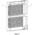
- the water-cooled heat dissipation device includes a first water-cooled plate 1 and a sealing plate 2.
- a water inlet and a water outlet may be arranged at corresponding positions of the first water-cooled plate 1 and the sealing plate 2 as required, which is not limited in this application.
- the first water-cooled plate 1 includes a first water-cooled substrate 1-1 and multiple first heat dissipation fins 1-3 arranged on the first water-cooled substrate 1-1.
- the first heat dissipation fins 1-3 may have a flat plate structure or a curved structure or the like.
- the first heat dissipation fins 1-3 may be mounted on the first water-cooled substrate 1-1 by gluing, welding or the like. Preferably, any two adjacent first heat dissipation fins 1-3 have a same spacing.
- the sealing plate 2 includes a sealing plate substrate 2-1 and multiple second heat dissipation fins 2-2 arranged on the sealing plate substrate 2-1 and each arranged between two first heat dissipation fins 1-3, and one second heat dissipation fin 2-2 is provided between the two first heat dissipation fins 1-3.
- the second heat dissipation fins 2-2 may have a flat plate structure or a curved structure or the like.
- the second heat dissipation fins 2-2 may be mounted on the first water-cooled substrate 1-1 by gluing, welding or the like. Preferably, any two adjacent second heat dissipation fins 2-2 have a same spacing.
- the first heat dissipation fins 1-3 and the second heat dissipation fins 2-2 are arranged alternately in sequence. That is, one second heat dissipation fin 2-2 is provided between the two adjacent first heat dissipation fins 1-3.
- the first water-cooled plate 1 and/or the sealing plate 2 have/has an integrally formed structure.
- the first water-cooled plate 1 and/or the sealing plate 2 have/has a die-casting structure.
- the first water-cooled plate 1 and the sealing plate 2 have a die-casting structure, which may both be an aluminum member.
- spacing between the two adjacent first heat dissipation fins 1-3 is equal to spacing between the two adjacent second heat dissipation fins 2-2.
- the first water-cooled plate 1 and the sealing plate 2 are formed by die-casting, so that the problem of water-cooled heat dissipation with large loss is solved at low cost, which effectively enhances the heat dissipation capacity of the water-cooled system, reduces the cost, and has strong practicability.
- the first water-cooled substrate 1-1 is hermetically matched with the sealing plate substrate 2-1 to form a water-cooled cavity 1-2 for accommodating the first heat dissipation fins 1-3 and the second heat dissipation fins 2-2.
- the water-cooled cavity 1-2 may be provided in a groove structure on the first water-cooled substrate 1-1.
- a heat generation module 3 is attached to an outside of the first water-cooled substrate 1-1, and the heat of the heat generation module 3 is taken away by the water flowing in the water-cooled cavity 1-2.
- the first heat dissipation fins 1-3 are formed by die-casting on the first water-cooled substrate 1-1
- the corresponding second heat dissipation fins 2-2 are formed by die-casting on the sealing plate 2, so that the first water-cooled plate 1 and the sealing plate 2 may be mounted in a staggered position together to form the water-cooled cavity 1-2.
- a heat dissipation area of the fins may be doubled, thereby effectively improving the heat dissipation efficiency of the water-cooled heat dissipation device.
- the water-cooled heat dissipation device further includes a first heat-conducting component with one end connected to the first water-cooled substrate 1-1 and the other end connected to the second heat dissipation fins 2-2.
- one of the first water-cooled substrate 1-1 and the second heat dissipation fin 2-2 is fixedly connected to the first heat-conducting component, and the other one of the first water-cooled substrate 1-1 and the second heat dissipation fin 2-2 abuts against the first heat-conducting component.
- the first heat-conducting component is made of material with relatively high thermal conductivity.
- the first heat-conducting component includes a first elastic compression member 4, a first end of the first elastic compression member 4 is connected to the first water-cooled substrate 1-1, and a second end of the first elastic compression member 4 is connected to free ends of the second heat dissipation fins 2-2.
- the first elastic compression member 4 may be a spring.
- the second end of the first elastic compression member 4 is a heat-conducting plane which abuts against the second heat dissipation fins 2-2.
- the spring type may be a flat spring so as to increase a contact area between the second heat dissipation fins 2-2 and the first water-cooled substrate 1-1.
- the first heat-conducting component includes a first heat-conducting plate connected at the second end of the first elastic compression member 4, and the first elastic compression member 4 abuts against the second heat dissipation fins 2-2 through the first heat-conducting plate.
- the first heat-conducting plate By providing the first heat-conducting plate, on one hand, the heat-conducting area is increased, and on the other hand, the first heat-conducting component is in stable contact with the second heat dissipation fin 2-2.
- the first elastic compression member 4 may be mounted by welding, gluing, crimping, interference fit, etc., and the spring material may be made of metal with a relatively high thermal conductivity, which is able to enhance the heat dissipation effect of the second heat dissipation fins 2-2.
- first elastic compression members 4 are arranged between the two adjacent first heat dissipation fins 1-3. Specifically, any two adjacent first elastic compression members 4 in the same row have a same spacing.
- the first heat-conducting component is first heat-conducting glue 5 filled at a groove bottom of the two adjacent first heat dissipation fins 1-3.
- the first heat-conducting glue 5 is heat-conducting glue with a relatively high thermal conductivity.
- the second heat dissipation fin 2-2 may be connected to the first water-cooled substrate 1-1 through the first heat-conducting glue 5.
- the sealing plate 2 is used as a second water-cooled plate
- the sealing plate substrate 2-1 is used as a second water-cooled substrate
- the water-cooled heat dissipation device further includes a second heat-conducting component with one end connected to the first heat dissipation fin 1-3 and the other end connected to the sealing plate substrate 2-1.
- one of the sealing plate substrate 2-1 and the first heat dissipation fin 1-3 is fixedly connected to the second heat-conducting component, and the other one of the sealing plate substrate 2-1 and the first heat dissipation fin 1-3 abuts against the second heat-conducting component.
- the second heat-conducting component is made of material with relatively high thermal conductivity.
- the second heat-conducting component includes a second elastic compression member 7, a first end of the second elastic compression member 7 is connected to the sealing plate substrate 2-1, and a second end of the second elastic compression member 7 is connected to free ends of the first heat dissipation fins 1-3.
- the second elastic compression member 7 may be a spring.
- the second end of the second elastic compression member 7 is a heat-conducting plane which abuts against the first heat dissipation fins 1-3.
- the spring type may be a flat spring so as to increase a contact area between the first heat dissipation fins 1-3 and the sealing plate substrate 2-1.
- the second elastic compression member 7 may be mounted by welding, gluing, crimping, interference fit, etc., and the spring material may be made of metal with a relatively high thermal conductivity, which is able to enhance the heat dissipation effect of the first heat dissipation fins 1-3.
- the second heat-conducting component includes a second heat-conducting plate connected at the second end of the second elastic compression member 7, and the second elastic compression member 7 abuts against the first heat dissipation fin 1-3 through the second heat-conducting plate.
- multiple second elastic compression members 7 are arranged between the two adjacent second heat dissipation fins. Specifically, any two adjacent second elastic compression members 7 in the same row have a same spacing.
- the second heat-conducting component is second heat-conducting glue 6 filled at a groove bottom of the two adjacent second heat dissipation fins 2-2.
- the second heat-conducting glue 6 is heat-conducting glue with a relatively high thermal conductivity.
- the first heat dissipation fins 1-3 may be connected to the sealing plate substrate 2-1 through the second heat-conducting glue 6.
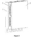
- An electrical device includes a water-cooled heat dissipation device and a heat generation module 3 arranged on the water-cooled heat dissipation device, and the water-cooled heat dissipation device is the water-cooled heat dissipation device according to any one of the above.
- the electrical device is an electric vehicle controller, or the electrical device may be other electrical device structures.
- the specific structure of the water-cooled heat dissipation device has been described above. And this application includes the above water-cooled heat dissipation device, which also has the above technical effects.
Landscapes
- Engineering & Computer Science (AREA)
- Microelectronics & Electronic Packaging (AREA)
- Physics & Mathematics (AREA)
- Thermal Sciences (AREA)
- Mechanical Engineering (AREA)
- General Engineering & Computer Science (AREA)
- Cooling Or The Like Of Electrical Apparatus (AREA)
- Cooling Or The Like Of Semiconductors Or Solid State Devices (AREA)
Abstract
Description
- The present application relates to the technical field of heat dissipation of electrical devices, and in particular to a water-cooler heat dissipation device. Another object of the present application is to provide an electrical device including the above water-cooler heat dissipation device.
- For heat dissipation mounted with a heating device, natural cooling and air cooling are generally used to dissipate heat. However, for an electrical device with high heat flux density, air cooling can no longer meet the heat dissipation requirement, and a liquid cooling method with a relatively great heat exchange capacity is required for heat dissipation.
- For example, the liquid cooling method is used by an electric vehicle controller, and a water-cooled plate of the electric vehicle controller is generally designed with different sizes of fins in a cavity to form different water passages, so that an area of a tooth is as large as possible and a heat dissipation area of the water-cooled plate is increased. A conventional water-cooled heat dissipation device is formed by die-casting. However, due to the limitation of the die-casting molding process, the heat dissipation fins cannot be thinned and the tooth spacing is reduced, which also limits the heat dissipation area of the tooth, and results in poor heat dissipation efficiency of the water-cooled heat dissipation device.
- Therefore, those skilled in the art have a strong desire is how to improve the heat dissipation efficiency of the water-cooled heat dissipation device.
- An object according to the present application is to provide a water-cooled heat dissipation device, so as to improve the heat dissipation efficiency of the water-cooled heat dissipation device. Another object according to the present application is to provide an electrical device including the above water-cooled heat dissipation device.
- In order to achieve the above objects, a water-cooled heat dissipation device is provided according to the present application, which includes a first water-cooled plate and a sealing plate. The first water-cooled plate includes a first water-cooled substrate and multiple first heat dissipation fins arranged on the first water-cooled substrate. The sealing plate includes a sealing plate substrate and multiple second heat dissipation fins arranged on the sealing plate substrate and each arranged between two first heat dissipation fins, and the first water-cooled substrate is hermetically matched with the sealing plate substrate to form a water-cooled cavity for accommodating the multiple first heat dissipation fins and the multiple second heat dissipation fins.
- Preferably, the water-cooled heat dissipation device includes a first heat-conducting component with one end connected to the first water-cooled substrate and the other end connected to the second heat dissipation fins.
- Preferably, the first heat-conducting component includes a first elastic compression member, a first end of the first elastic compression member is connected to the first water-cooled substrate, and a second end of the first elastic compression member is connected to free ends of the second heat dissipation fins.
- Preferably, the first heat-conducting component includes a first heat-conducting plate connected at the second end of the first elastic compression member, and the first elastic compression member abuts against the second heat dissipation fins through the first heat-conducting plate.
- Preferably, the first elastic compression member is a spring, and the second end of the first elastic compression member is a heat-conducting plane which abuts against the first heat dissipation fins.
- Preferably, multiple first elastic compression members are arranged between two adjacent first heat dissipation fins.
- Preferably, the first heat-conducting component is first heat-conducting glue filled at a groove bottom of the two adjacent first heat dissipation fins.
- Preferably, the sealing plate is a second water-cooled plate, and the water-cooled heat dissipation device further includes a second heat-conducting component with one end connected to the first heat dissipation fins and the other end connected to the sealing plate substrate.
- Preferably, the second heat-conducting component includes a second elastic compression member, a first end of the second elastic compression member is connected to the sealing plate substrate, and a second end of the second elastic compression member is connected to free ends of the first heat dissipation fins.
- Preferably, the second heat-conducting component includes a second heat-conducting plate connected at the second end of the second elastic compression member, and the second elastic compression member abuts against the first heat dissipation fins through the second heat-conducting plate.
- Preferably, the second elastic compression member is a spring, and the second end of the second elastic compression member is a heat-conducting plane which abuts against the first heat dissipation fins.
- Preferably, multiple second elastic compression members are arranged between two adjacent second heat dissipation fins.
- Preferably, the second heat-conducting component is second heat-conducting glue filled at a groove bottom of the two adjacent second heat dissipation fins.
- Preferably, spacing between the two adjacent first heat dissipation fins is equal to spacing between the two adjacent second heat dissipation fins.
- Preferably, the multiple first heat dissipation fins and the multiple second heat dissipation fins are arranged alternately in sequence.
- Preferably, the first water-cooled plate and/or the sealing plate have/has an integrally formed structure.
- Preferably, the first water-cooled plate and/or the sealing plate have/has a die-casting structure.
- An electrical device includes a water-cooled heat dissipation device and a heat generating module arranged on the water-cooled heat dissipation device, and the water-cooled heat dissipation device is the water-cooled heat dissipation device according to any one of the above.
- Preferably, the electrical device is an electric vehicle controller.
- In the above technical solution, the water-cooled heat dissipation device according to the present application includes the first water-cooled plate and the sealing plate. The first water-cooled plate includes a first water-cooled substrate and the first heat dissipation fins arranged on the first water-cooled substrate. The sealing plate includes the sealing plate substrate and the second heat dissipation fins arranged on the sealing plate substrate and each arranged between two first heat dissipation fins, and the first water-cooled substrate is hermetically matched with the sealing plate substrate to form the water-cooled cavity for accommodating the first heat dissipation fins and the second heat dissipation fins.
- As can be seen from the above description, in the water-cooled heat dissipation device according to the present application, the second heat dissipation fins are provided on the sealing plate substrate, so as to increases the overall heat dissipation area of the water-cooled heat dissipation device, thereby improving the heat dissipation efficiency of the water-cooled heat dissipation device.
- For more clearly illustrating embodiments of the present application or the technical solutions in the conventional technology, drawings to be used in the description of the embodiments or the conventional technology will be briefly described hereinafter. Apparently, the drawings in the following description are only some embodiments of the present application. For those skilled in the art, other drawings may be obtained based on the provided drawings without any creative work.
-
Figure 1 is a three-dimensional structural sectional diagram of a water-cooled heat dissipation device according to an embodiment of the present application; -
Figure 2 is a three-dimensional structural diagram of an electrical device according to an embodiment of the present application; -
Figure 3 is a schematic structural diagram of a first water-cooled plate according to an embodiment of the present application; -
Figure 4 is a schematic structural diagram of a sealing plate according to an embodiment of the present application; -
Figure 5 is a partial schematic structural diagram of a first water-cooled heat dissipation device according to an embodiment of the present application; -
Figure 6 is a three-dimensional structural diagram of the first water-cooled heat dissipation device inFIG. 5 ; - Figure is a partial schematic structural diagram of a second water-cooled heat dissipation device according to an embodiment of the present application;
-
Figure 8 is a partial schematic structural diagram of a third water-cooled heat dissipation device according to an embodiment of the present application; -
Figure 9 is a partial schematic structural diagram of a fourth water-cooled heat dissipation device according to an embodiment of the present application; -
Figure 10 is a partial schematic structural diagram of a fifth water-cooled heat dissipation device according to an embodiment of the present application. - A core of the present application is to provide a water-cooled heat dissipation device, so as to improve the heat dissipation efficiency of the water-cooled heat dissipation device. Another object according to the present application is to provide an electrical device including the above water-cooled heat dissipation device.
- In order to enable those skilled in the art to better understand the technical solutions of the present application, the present application will be further described in detail below with reference to the drawings and embodiments.
- References are made to
Figure 1 to 10 . - In a specific embodiment, the water-cooled heat dissipation device according to an embodiment of the present application includes a first water-cooled
plate 1 and asealing plate 2. Specifically, a water inlet and a water outlet may be arranged at corresponding positions of the first water-cooledplate 1 and thesealing plate 2 as required, which is not limited in this application. - The first water-cooled
plate 1 includes a first water-cooled substrate 1-1 and multiple first heat dissipation fins 1-3 arranged on the first water-cooled substrate 1-1. Specifically, the first heat dissipation fins 1-3 may have a flat plate structure or a curved structure or the like. The first heat dissipation fins 1-3 may be mounted on the first water-cooled substrate 1-1 by gluing, welding or the like. Preferably, any two adjacent first heat dissipation fins 1-3 have a same spacing. - The
sealing plate 2 includes a sealing plate substrate 2-1 and multiple second heat dissipation fins 2-2 arranged on the sealing plate substrate 2-1 and each arranged between two first heat dissipation fins 1-3, and one second heat dissipation fin 2-2 is provided between the two first heat dissipation fins 1-3. Specifically, the second heat dissipation fins 2-2 may have a flat plate structure or a curved structure or the like. The second heat dissipation fins 2-2 may be mounted on the first water-cooled substrate 1-1 by gluing, welding or the like. Preferably, any two adjacent second heat dissipation fins 2-2 have a same spacing. - As shown in
Figure 5 , preferably, the first heat dissipation fins 1-3 and the second heat dissipation fins 2-2 are arranged alternately in sequence. That is, one second heat dissipation fin 2-2 is provided between the two adjacent first heat dissipation fins 1-3. - In order to improve assembly efficiency, preferably, the first water-cooled
plate 1 and/or the sealingplate 2 have/has an integrally formed structure. Specifically, the first water-cooledplate 1 and/or the sealingplate 2 have/has a die-casting structure. The first water-cooledplate 1 and the sealingplate 2 have a die-casting structure, which may both be an aluminum member. - Specifically, in order to improve the uniformity of heat dissipation, preferably, spacing between the two adjacent first heat dissipation fins 1-3 is equal to spacing between the two adjacent second heat dissipation fins 2-2.
- The first water-cooled
plate 1 and the sealingplate 2 are formed by die-casting, so that the problem of water-cooled heat dissipation with large loss is solved at low cost, which effectively enhances the heat dissipation capacity of the water-cooled system, reduces the cost, and has strong practicability. - The first water-cooled substrate 1-1 is hermetically matched with the sealing plate substrate 2-1 to form a water-cooled cavity 1-2 for accommodating the first heat dissipation fins 1-3 and the second heat dissipation fins 2-2. Specifically, the water-cooled cavity 1-2 may be provided in a groove structure on the first water-cooled substrate 1-1.
- Specifically, a
heat generation module 3 is attached to an outside of the first water-cooled substrate 1-1, and the heat of theheat generation module 3 is taken away by the water flowing in the water-cooled cavity 1-2. Specifically, the first heat dissipation fins 1-3 are formed by die-casting on the first water-cooled substrate 1-1, and the corresponding second heat dissipation fins 2-2 are formed by die-casting on the sealingplate 2, so that the first water-cooledplate 1 and the sealingplate 2 may be mounted in a staggered position together to form the water-cooled cavity 1-2. On this basis, a heat dissipation area of the fins may be doubled, thereby effectively improving the heat dissipation efficiency of the water-cooled heat dissipation device. - Due to the assembly and processing errors of the first water-cooled
plate 1 and the sealingplate 2, the second heat dissipation fins 2-2 may not be possible to closely fit with the first water-cooled substrate 1-1. Preferably, the water-cooled heat dissipation device further includes a first heat-conducting component with one end connected to the first water-cooled substrate 1-1 and the other end connected to the second heat dissipation fins 2-2. In order to facilitate assembly and disassembly, preferably, one of the first water-cooled substrate 1-1 and the second heat dissipation fin 2-2 is fixedly connected to the first heat-conducting component, and the other one of the first water-cooled substrate 1-1 and the second heat dissipation fin 2-2 abuts against the first heat-conducting component. Specifically, the first heat-conducting component is made of material with relatively high thermal conductivity. - As shown in
Figure 7 , the first heat-conducting component includes a firstelastic compression member 4, a first end of the firstelastic compression member 4 is connected to the first water-cooled substrate 1-1, and a second end of the firstelastic compression member 4 is connected to free ends of the second heat dissipation fins 2-2. - Specifically, the first
elastic compression member 4 may be a spring. In order to improve the thermal conduction efficiency, preferably, the second end of the firstelastic compression member 4 is a heat-conducting plane which abuts against the second heat dissipation fins 2-2. That is, the spring type may be a flat spring so as to increase a contact area between the second heat dissipation fins 2-2 and the first water-cooled substrate 1-1. - Preferably, the first heat-conducting component includes a first heat-conducting plate connected at the second end of the first
elastic compression member 4, and the firstelastic compression member 4 abuts against the second heat dissipation fins 2-2 through the first heat-conducting plate. By providing the first heat-conducting plate, on one hand, the heat-conducting area is increased, and on the other hand, the first heat-conducting component is in stable contact with the second heat dissipation fin 2-2. - Specifically, the first
elastic compression member 4 may be mounted by welding, gluing, crimping, interference fit, etc., and the spring material may be made of metal with a relatively high thermal conductivity, which is able to enhance the heat dissipation effect of the second heat dissipation fins 2-2. - In order to further improve the thermal conduction effect, preferably, multiple first
elastic compression members 4 are arranged between the two adjacent first heat dissipation fins 1-3. Specifically, any two adjacent firstelastic compression members 4 in the same row have a same spacing. - As shown in
Figure 8 , in another embodiment, the first heat-conducting component is first heat-conductingglue 5 filled at a groove bottom of the two adjacent first heat dissipation fins 1-3. Specifically, the first heat-conductingglue 5 is heat-conducting glue with a relatively high thermal conductivity. Specifically, the second heat dissipation fin 2-2 may be connected to the first water-cooled substrate 1-1 through the first heat-conductingglue 5. - In a case that the
heat generation modules 3 are mounted on two sides of the water-cooled heat dissipation device, preferably, the sealingplate 2 is used as a second water-cooled plate, the sealing plate substrate 2-1 is used as a second water-cooled substrate, and the water-cooled heat dissipation device further includes a second heat-conducting component with one end connected to the first heat dissipation fin 1-3 and the other end connected to the sealing plate substrate 2-1. By providing the second heat-conducting component, the heat of theheat generation module 3 on the second water-cooled plate may be taken out as soon as possible. - In order to facilitate assembly and disassembly, preferably, one of the sealing plate substrate 2-1 and the first heat dissipation fin 1-3 is fixedly connected to the second heat-conducting component, and the other one of the sealing plate substrate 2-1 and the first heat dissipation fin 1-3 abuts against the second heat-conducting component. Specifically, the second heat-conducting component is made of material with relatively high thermal conductivity.
- As shown in
Figure 10 , specifically, the second heat-conducting component includes a secondelastic compression member 7, a first end of the secondelastic compression member 7 is connected to the sealing plate substrate 2-1, and a second end of the secondelastic compression member 7 is connected to free ends of the first heat dissipation fins 1-3. - Specifically, the second
elastic compression member 7 may be a spring. In order to improve the thermal conduction efficiency, preferably, the second end of the secondelastic compression member 7 is a heat-conducting plane which abuts against the first heat dissipation fins 1-3. That is, the spring type may be a flat spring so as to increase a contact area between the first heat dissipation fins 1-3 and the sealing plate substrate 2-1. - Specifically, the second
elastic compression member 7 may be mounted by welding, gluing, crimping, interference fit, etc., and the spring material may be made of metal with a relatively high thermal conductivity, which is able to enhance the heat dissipation effect of the first heat dissipation fins 1-3. - In an embodiment, the second heat-conducting component includes a second heat-conducting plate connected at the second end of the second
elastic compression member 7, and the secondelastic compression member 7 abuts against the first heat dissipation fin 1-3 through the second heat-conducting plate. By providing the second heat-conducting plate, on one hand, the heat-conducting area is increased, and on the other hand, the second heat-conducting component is in stable contact with the first heat dissipation fins 1-3. - In order to further improve the thermal conduction effect, preferably, multiple second
elastic compression members 7 are arranged between the two adjacent second heat dissipation fins. Specifically, any two adjacent secondelastic compression members 7 in the same row have a same spacing. - As shown in
Figure 9 . In another embodiment, the second heat-conducting component is second heat-conductingglue 6 filled at a groove bottom of the two adjacent second heat dissipation fins 2-2. Specifically, the second heat-conductingglue 6 is heat-conducting glue with a relatively high thermal conductivity. Specifically, the first heat dissipation fins 1-3 may be connected to the sealing plate substrate 2-1 through the second heat-conductingglue 6. - An electrical device according to the present application includes a water-cooled heat dissipation device and a
heat generation module 3 arranged on the water-cooled heat dissipation device, and the water-cooled heat dissipation device is the water-cooled heat dissipation device according to any one of the above. Specifically, the electrical device is an electric vehicle controller, or the electrical device may be other electrical device structures. The specific structure of the water-cooled heat dissipation device has been described above. And this application includes the above water-cooled heat dissipation device, which also has the above technical effects. - The above embodiments are described in a progressive manner. Each of the embodiments is mainly focused on describing its differences from other embodiments, and reference may be made among these embodiments with respect to the same or similar parts.
- The above illustration of the disclosed embodiments can enable those skilled in the art to implement or use the present application. Various modifications to the embodiments are apparent to the person skilled in the art, and the general principle herein can be implemented in other embodiments without departing from the spirit or scope of the present application. Therefore, the present application is not limited to the embodiments described herein, but should be in accordance with the broadest scope consistent with the principle and novel features disclosed herein.
| 1 | first water-cooled plate; | 1-1 | first water-cooled substrate; |
| 1-2 | water cooled cavity; | 1-3 | first heat dissipation fin; |
| 2 | sealing plate; | 2-1 | sealing plate substrate; |
| 2-2 | second heat dissipation fin; | 3 | heat generation module; |
| 4 | first elastic compression member; | 5 | first heat-conducting glue; |
| 6 | second heat-conducting glue; | 7 | second elastic compression member. |
Claims (19)
- A water-cooled heat dissipation device, comprising a first water-cooled plate (1) and a sealing plate (2); whereinthe first water-cooled plate (1) comprises a first water-cooled substrate (1-1) and a plurality of first heat dissipation fins (1-3) arranged on the first water-cooled substrate (1-1); andthe sealing plate (2) comprises a sealing plate substrate (2-1) and a plurality of second heat dissipation fins (2-2) arranged on the sealing plate substrate (2-1) and each arranged between two of the plurality of first heat dissipation fins (1-3), and the first water-cooled substrate (1-1) is hermetically matched with the sealing plate substrate (2-2) to form a water-cooled cavity (1-2) for accommodating the plurality of first heat dissipation fins (1-3) and the plurality of second heat dissipation fins (2-2).
- The water-cooled heat dissipation device according to claim 1, further comprising a first heat-conducting component with one end connected to the first water-cooled substrate (1-1) and the other end connected to the second heat dissipation fins (2-2).
- The water-cooled heat dissipation device according to claim 2, wherein the first heat-conducting component comprises a first elastic compression member (4), a first end of the first elastic compression member (4) is connected to the first water-cooled substrate (1-1), and a second end of the first elastic compression member (4) is connected to free ends of the second heat dissipation fins (2-2).
- The water-cooled heat dissipation device according to claim 3, wherein the first heat-conducting component comprises a first heat-conducting plate connected at the second end of the first elastic compression member (4), and the first elastic compression member (4) abuts against the second heat dissipation fins (2-2) through the first heat-conducting plate.
- The water-cooled heat dissipation device according to claim 3, wherein the first elastic compression member (4) is a spring, and the second end of the first elastic compression member (4) is a heat-conducting plane which abuts against the first heat dissipation fins (1-3).
- The water-cooled heat dissipation device according to claim 3, wherein a plurality of first elastic compression members (4) are arranged between two adjacent first heat dissipation fins (1-3).
- The water-cooled heat dissipation device according to claim 2, wherein the first heat-conducting component is first heat-conducting glue (5) filled at a groove bottom of the two adjacent first heat dissipation fins (1-3).
- The water-cooled heat dissipation device according to claim 2, wherein the sealing plate (2) is a second water-cooled plate, and the water-cooled heat dissipation device comprises a second heat-conducting component with one end connected to the first heat dissipation fins (1-3) and the other end connected with the sealing plate substrate (2-1).
- The water-cooled heat dissipation device according to claim 8, wherein the second heat-conducting component comprises a second elastic compression member (7), a first end of the second elastic compression member (7) is connected to the sealing plate substrate (2-1), and a second end of the second elastic compression member (7) is connected to free ends of the first heat dissipation fins (1-3).
- The water-cooled heat dissipation device according to claim 9, wherein the second heat-conducting component comprises a second heat-conducting plate connected at the second end of the second elastic compression member (7), and the second elastic compression member (7) abuts against the first heat dissipation fins (1-3) through the second heat-conducting plate.
- The water-cooled heat dissipation device according to claim 10, wherein the second elastic compression member (7) is a spring, and the second end of the second elastic compression member (7) is a heat-conducting plane which abuts against the first heat dissipation fins (1-3).
- The water-cooled heat dissipation device according to claim 9, wherein a plurality of second elastic compression members (7) are arranged between two adjacent second heat dissipation fins.
- The water-cooled heat dissipation device according to claim 8, wherein the second heat-conducting component is second heat-conducting glue (6) filled at a groove bottom of the two adjacent second heat dissipation fins (2-2).
- The water-cooled heat dissipation device according to claim 1, wherein spacing between the two adjacent first heat dissipation fins (1-3) is equal to spacing between the two adjacent second heat dissipation fins (2-2).
- The water-cooled heat dissipation device according to claim 1, wherein the plurality of first heat dissipation fins (1-3) and the plurality of second heat dissipation fins (2-2) are arranged alternately in sequence.
- The water-cooled heat dissipation device according to any one of claims 1 to 15, wherein the first water-cooled plate (1) and/or the sealing plate (2) have/has an integrally formed structure.
- The water-cooled heat dissipation device according to claim 16, wherein the first water-cooled plate (1) and/or the sealing plate (2) have/has a die-casting structure.
- An electrical device, comprising a water-cooled heat dissipation device and a heat generation module (3) arranged on the water-cooled heat dissipation device, wherein the water-cooled heat dissipation device is the water-cooled heat dissipation device according to any one of claims 1 to 17.
- The electrical device according to claim 18, wherein the electrical device is an electric vehicle controller.
Applications Claiming Priority (1)
| Application Number | Priority Date | Filing Date | Title |
|---|---|---|---|
| CN202011204606.9A CN112292007A (en) | 2020-11-02 | 2020-11-02 | Water-cooling heat dissipation device and electrical apparatus |
Publications (2)
| Publication Number | Publication Date |
|---|---|
| EP3993587A1 true EP3993587A1 (en) | 2022-05-04 |
| EP3993587B1 EP3993587B1 (en) | 2023-10-04 |
Family
ID=74353981
Family Applications (1)
| Application Number | Title | Priority Date | Filing Date |
|---|---|---|---|
| EP21192686.0A Active EP3993587B1 (en) | 2020-11-02 | 2021-08-23 | Water-cooler heat dissipation device and electrical device |
Country Status (4)
| Country | Link |
|---|---|
| US (1) | US20220142009A1 (en) |
| EP (1) | EP3993587B1 (en) |
| CN (1) | CN112292007A (en) |
| ES (1) | ES2966071T3 (en) |
Cited By (2)
| Publication number | Priority date | Publication date | Assignee | Title |
|---|---|---|---|---|
| CN115051677A (en) * | 2022-06-21 | 2022-09-13 | 北京中科飞鸿科技股份有限公司 | Balanced SAW Filter |
| CN115275436A (en) * | 2022-09-13 | 2022-11-01 | 青岛科技大学 | Heat dissipation device for new energy battery box |
Families Citing this family (2)
| Publication number | Priority date | Publication date | Assignee | Title |
|---|---|---|---|---|
| CN115512935B (en) * | 2022-11-10 | 2025-04-29 | 安徽兆晟新能源科技有限公司 | A water-cooled special transformer |
| CN117213285A (en) * | 2023-09-06 | 2023-12-12 | 中国工程物理研究院核物理与化学研究所 | High-temperature coupling heat transfer interface adopting variable thermal resistance and application thereof |
Citations (4)
| Publication number | Priority date | Publication date | Assignee | Title |
|---|---|---|---|---|
| EP0717440B1 (en) * | 1994-12-15 | 2003-04-23 | Hitachi, Ltd. | Cooling device of multi-chip module |
| US20150008574A1 (en) * | 2012-09-19 | 2015-01-08 | Fuji Electric Co., Ltd. | Semiconductor device and method for manufacturing semiconductor device |
| EP3217137A1 (en) * | 2016-03-10 | 2017-09-13 | Commissariat à l'Energie Atomique et aux Energies Alternatives | Device for thermally cooling an object from a cold source such as a cryogenic fluid bath |
| CN108302970A (en) * | 2017-01-13 | 2018-07-20 | 双鸿科技股份有限公司 | Water cooling head |
Family Cites Families (28)
| Publication number | Priority date | Publication date | Assignee | Title |
|---|---|---|---|---|
| US3524497A (en) * | 1968-04-04 | 1970-08-18 | Ibm | Heat transfer in a liquid cooling system |
| US6898082B2 (en) * | 2002-05-10 | 2005-05-24 | Serguei V. Dessiatoun | Enhanced heat transfer structure with heat transfer members of variable density |
| JP4325219B2 (en) * | 2003-02-26 | 2009-09-02 | 日本電気株式会社 | Electronic device casing structure and method for adjusting the pressure inside the sealed casing |
| US20060087816A1 (en) * | 2004-09-21 | 2006-04-27 | Ingo Ewes | Heat-transfer devices |
| US7408780B2 (en) * | 2005-06-14 | 2008-08-05 | International Business Machines Corporation | Compliant thermal interface structure utilizing spring elements with fins |
| TWM289878U (en) * | 2005-11-11 | 2006-04-21 | Cooler Master Co Ltd | Heat-dissipation structure of water-cooling type parallel runner |
| US8094453B2 (en) * | 2009-09-30 | 2012-01-10 | International Business Machines Corporation | Compliant conduction rail assembly and method facilitating cooling of an electronics structure |
| WO2012114475A1 (en) * | 2011-02-23 | 2012-08-30 | トヨタ自動車株式会社 | Cooling device |
| CN102394229A (en) * | 2011-09-28 | 2012-03-28 | 中国北车集团大连机车研究所有限公司 | Plate radiator |
| CN102563998A (en) * | 2011-12-26 | 2012-07-11 | 联合汽车电子有限公司 | Flat water-cooling heat radiation device |
| CN202816913U (en) * | 2012-10-24 | 2013-03-20 | 中国电子科技集团公司第三十八研究所 | Microchannel liquid-cooled heat sink device |
| CN103747654A (en) * | 2013-12-24 | 2014-04-23 | 周细文 | Water cooling plate for heat dissipation of high-power electrical heating element |
| US10178805B2 (en) * | 2014-05-23 | 2019-01-08 | Tesla, Inc. | Heatsink with internal cavity for liquid cooling |
| CN204272577U (en) * | 2014-12-14 | 2015-04-15 | 天津芯之铠热管理技术研发有限公司 | A kind of two-way laminating cooled plate |
| CN204809210U (en) * | 2015-06-04 | 2015-11-25 | 番禺得意精密电子工业有限公司 | Elasticity conducting strip |
| US10265812B2 (en) * | 2015-08-12 | 2019-04-23 | International Business Machines Corporation | Liquid-cooled, composite heat sink assemblies |
| CN205080487U (en) * | 2015-09-09 | 2016-03-09 | 番禺得意精密电子工业有限公司 | Elasticity conducting strip |
| CN206674409U (en) * | 2017-03-21 | 2017-11-24 | 株洲中车奇宏散热技术有限公司 | A kind of band two-sided cooled plate of fin structure |
| CN206610885U (en) * | 2017-03-31 | 2017-11-03 | 北京畅的科技开发有限公司 | A kind of cooling device of new-energy automobile |
| CN107104086B (en) * | 2017-05-18 | 2019-01-29 | 苏州汇川联合动力系统有限公司 | Liquid cooling device and motor controller |
| CN207573821U (en) * | 2017-12-14 | 2018-07-03 | 苏州众能医疗科技有限公司 | A kind of two-sided water cooling plate heat dissipating device |
| CN107995837A (en) * | 2017-12-28 | 2018-05-04 | 深圳红河马智能数字动力技术有限公司 | Air-cooled, water cooling two uses radiator |
| CN110197935B (en) * | 2018-02-27 | 2021-11-12 | 格朗吉斯铝业(上海)有限公司 | Water cooling plate for battery module |
| CN111206975A (en) * | 2018-11-22 | 2020-05-29 | 扬州恒旺热交换器有限公司 | Oil cooler core |
| CN110631386B (en) * | 2019-09-09 | 2020-09-25 | 贵州永红航空机械有限责任公司 | Micro-channel plate-fin heat exchanger and forming and assembling method |
| CN211656029U (en) * | 2020-03-24 | 2020-10-09 | 新乡市振源电器股份有限公司 | A Soft-Start Controller With Overload Protection |
| CN211792640U (en) * | 2020-04-14 | 2020-10-27 | 株洲中车时代电气股份有限公司 | Water-cooling radiating fin structure for motor controller |
| CN111698882A (en) * | 2020-06-27 | 2020-09-22 | 江苏海鼎电气科技有限公司 | Internal drainage type water-cooling air-cooling electronic electric heat dissipation device |
-
2020
- 2020-11-02 CN CN202011204606.9A patent/CN112292007A/en active Pending
-
2021
- 2021-08-20 US US17/408,286 patent/US20220142009A1/en not_active Abandoned
- 2021-08-23 EP EP21192686.0A patent/EP3993587B1/en active Active
- 2021-08-23 ES ES21192686T patent/ES2966071T3/en active Active
Patent Citations (4)
| Publication number | Priority date | Publication date | Assignee | Title |
|---|---|---|---|---|
| EP0717440B1 (en) * | 1994-12-15 | 2003-04-23 | Hitachi, Ltd. | Cooling device of multi-chip module |
| US20150008574A1 (en) * | 2012-09-19 | 2015-01-08 | Fuji Electric Co., Ltd. | Semiconductor device and method for manufacturing semiconductor device |
| EP3217137A1 (en) * | 2016-03-10 | 2017-09-13 | Commissariat à l'Energie Atomique et aux Energies Alternatives | Device for thermally cooling an object from a cold source such as a cryogenic fluid bath |
| CN108302970A (en) * | 2017-01-13 | 2018-07-20 | 双鸿科技股份有限公司 | Water cooling head |
Cited By (2)
| Publication number | Priority date | Publication date | Assignee | Title |
|---|---|---|---|---|
| CN115051677A (en) * | 2022-06-21 | 2022-09-13 | 北京中科飞鸿科技股份有限公司 | Balanced SAW Filter |
| CN115275436A (en) * | 2022-09-13 | 2022-11-01 | 青岛科技大学 | Heat dissipation device for new energy battery box |
Also Published As
| Publication number | Publication date |
|---|---|
| CN112292007A (en) | 2021-01-29 |
| US20220142009A1 (en) | 2022-05-05 |
| EP3993587B1 (en) | 2023-10-04 |
| ES2966071T3 (en) | 2024-04-18 |
Similar Documents
| Publication | Publication Date | Title |
|---|---|---|
| EP3993587B1 (en) | Water-cooler heat dissipation device and electrical device | |
| KR101940577B1 (en) | Heating sink and power battery system | |
| JP5975110B2 (en) | Semiconductor device | |
| US9287193B2 (en) | Semiconductor device | |
| WO2022222759A1 (en) | Radiator, packaging structure, and electronic device | |
| EP3787387A1 (en) | Inverter and heat dissipation device thereof | |
| CN105916357A (en) | Power supply heat dissipation device based on cold plate and method thereof | |
| CN210200705U (en) | High-efficiency heat dissipation module | |
| JP6361597B2 (en) | Semiconductor device | |
| WO2026066969A1 (en) | Power-module heat dissipation structure and on-board charger using same | |
| CN115666100A (en) | Heat radiation structure and power module assembly | |
| JP2018063999A (en) | Semiconductor device | |
| CN222561999U (en) | Water cooling plate components | |
| JP6686848B2 (en) | Power module | |
| CN220489099U (en) | Water cooling device for ultra-high power solid-state light source | |
| CN211578734U (en) | Heat conducting device for electronic device | |
| CN211580493U (en) | Electronic component heat radiation assembly | |
| JP6468095B2 (en) | Semiconductor device | |
| CN211745055U (en) | High-efficiency radiator for electronic component | |
| CN216600653U (en) | Radiators and Cooling Devices | |
| CN217426895U (en) | Battery package and car | |
| CN221228136U (en) | Power converter | |
| CN211909490U (en) | High-efficiency heat dissipation device | |
| CN216600640U (en) | Radiator, power module and driver | |
| CN213126954U (en) | Radiator and intelligent electrical apparatus |
Legal Events
| Date | Code | Title | Description |
|---|---|---|---|
| PUAI | Public reference made under article 153(3) epc to a published international application that has entered the european phase |
Free format text: ORIGINAL CODE: 0009012 |
|
| STAA | Information on the status of an ep patent application or granted ep patent |
Free format text: STATUS: THE APPLICATION HAS BEEN PUBLISHED |
|
| AK | Designated contracting states |
Kind code of ref document: A1 Designated state(s): AL AT BE BG CH CY CZ DE DK EE ES FI FR GB GR HR HU IE IS IT LI LT LU LV MC MK MT NL NO PL PT RO RS SE SI SK SM TR |
|
| STAA | Information on the status of an ep patent application or granted ep patent |
Free format text: STATUS: REQUEST FOR EXAMINATION WAS MADE |
|
| 17P | Request for examination filed |
Effective date: 20220909 |
|
| RBV | Designated contracting states (corrected) |
Designated state(s): AL AT BE BG CH CY CZ DE DK EE ES FI FR GB GR HR HU IE IS IT LI LT LU LV MC MK MT NL NO PL PT RO RS SE SI SK SM TR |
|
| GRAP | Despatch of communication of intention to grant a patent |
Free format text: ORIGINAL CODE: EPIDOSNIGR1 |
|
| STAA | Information on the status of an ep patent application or granted ep patent |
Free format text: STATUS: GRANT OF PATENT IS INTENDED |
|
| RIC1 | Information provided on ipc code assigned before grant |
Ipc: F28F 13/00 20060101ALI20230425BHEP Ipc: H05K 7/20 20060101AFI20230425BHEP |
|
| INTG | Intention to grant announced |
Effective date: 20230526 |
|
| GRAS | Grant fee paid |
Free format text: ORIGINAL CODE: EPIDOSNIGR3 |
|
| P01 | Opt-out of the competence of the unified patent court (upc) registered |
Effective date: 20230718 |
|
| GRAA | (expected) grant |
Free format text: ORIGINAL CODE: 0009210 |
|
| STAA | Information on the status of an ep patent application or granted ep patent |
Free format text: STATUS: THE PATENT HAS BEEN GRANTED |
|
| AK | Designated contracting states |
Kind code of ref document: B1 Designated state(s): AL AT BE BG CH CY CZ DE DK EE ES FI FR GB GR HR HU IE IS IT LI LT LU LV MC MK MT NL NO PL PT RO RS SE SI SK SM TR |
|
| REG | Reference to a national code |
Ref country code: GB Ref legal event code: FG4D |
|
| REG | Reference to a national code |
Ref country code: CH Ref legal event code: EP |
|
| REG | Reference to a national code |
Ref country code: IE Ref legal event code: FG4D Ref country code: NL Ref legal event code: FP |
|
| REG | Reference to a national code |
Ref country code: DE Ref legal event code: R096 Ref document number: 602021005589 Country of ref document: DE |
|
| REG | Reference to a national code |
Ref country code: LT Ref legal event code: MG9D |
|
| REG | Reference to a national code |
Ref country code: AT Ref legal event code: MK05 Ref document number: 1619230 Country of ref document: AT Kind code of ref document: T Effective date: 20231004 |
|
| PG25 | Lapsed in a contracting state [announced via postgrant information from national office to epo] |
Ref country code: GR Free format text: LAPSE BECAUSE OF FAILURE TO SUBMIT A TRANSLATION OF THE DESCRIPTION OR TO PAY THE FEE WITHIN THE PRESCRIBED TIME-LIMIT Effective date: 20240105 |
|
| PG25 | Lapsed in a contracting state [announced via postgrant information from national office to epo] |
Ref country code: IS Free format text: LAPSE BECAUSE OF FAILURE TO SUBMIT A TRANSLATION OF THE DESCRIPTION OR TO PAY THE FEE WITHIN THE PRESCRIBED TIME-LIMIT Effective date: 20240204 |
|
| PG25 | Lapsed in a contracting state [announced via postgrant information from national office to epo] |
Ref country code: LT Free format text: LAPSE BECAUSE OF FAILURE TO SUBMIT A TRANSLATION OF THE DESCRIPTION OR TO PAY THE FEE WITHIN THE PRESCRIBED TIME-LIMIT Effective date: 20231004 |
|
| REG | Reference to a national code |
Ref country code: ES Ref legal event code: FG2A Ref document number: 2966071 Country of ref document: ES Kind code of ref document: T3 Effective date: 20240418 |
|
| PG25 | Lapsed in a contracting state [announced via postgrant information from national office to epo] |
Ref country code: AT Free format text: LAPSE BECAUSE OF FAILURE TO SUBMIT A TRANSLATION OF THE DESCRIPTION OR TO PAY THE FEE WITHIN THE PRESCRIBED TIME-LIMIT Effective date: 20231004 |
|
| PG25 | Lapsed in a contracting state [announced via postgrant information from national office to epo] |
Ref country code: LT Free format text: LAPSE BECAUSE OF FAILURE TO SUBMIT A TRANSLATION OF THE DESCRIPTION OR TO PAY THE FEE WITHIN THE PRESCRIBED TIME-LIMIT Effective date: 20231004 Ref country code: IS Free format text: LAPSE BECAUSE OF FAILURE TO SUBMIT A TRANSLATION OF THE DESCRIPTION OR TO PAY THE FEE WITHIN THE PRESCRIBED TIME-LIMIT Effective date: 20240204 Ref country code: GR Free format text: LAPSE BECAUSE OF FAILURE TO SUBMIT A TRANSLATION OF THE DESCRIPTION OR TO PAY THE FEE WITHIN THE PRESCRIBED TIME-LIMIT Effective date: 20240105 Ref country code: BG Free format text: LAPSE BECAUSE OF FAILURE TO SUBMIT A TRANSLATION OF THE DESCRIPTION OR TO PAY THE FEE WITHIN THE PRESCRIBED TIME-LIMIT Effective date: 20240104 Ref country code: AT Free format text: LAPSE BECAUSE OF FAILURE TO SUBMIT A TRANSLATION OF THE DESCRIPTION OR TO PAY THE FEE WITHIN THE PRESCRIBED TIME-LIMIT Effective date: 20231004 Ref country code: PT Free format text: LAPSE BECAUSE OF FAILURE TO SUBMIT A TRANSLATION OF THE DESCRIPTION OR TO PAY THE FEE WITHIN THE PRESCRIBED TIME-LIMIT Effective date: 20240205 |
|
| PG25 | Lapsed in a contracting state [announced via postgrant information from national office to epo] |
Ref country code: SE Free format text: LAPSE BECAUSE OF FAILURE TO SUBMIT A TRANSLATION OF THE DESCRIPTION OR TO PAY THE FEE WITHIN THE PRESCRIBED TIME-LIMIT Effective date: 20231004 Ref country code: RS Free format text: LAPSE BECAUSE OF FAILURE TO SUBMIT A TRANSLATION OF THE DESCRIPTION OR TO PAY THE FEE WITHIN THE PRESCRIBED TIME-LIMIT Effective date: 20231004 Ref country code: PL Free format text: LAPSE BECAUSE OF FAILURE TO SUBMIT A TRANSLATION OF THE DESCRIPTION OR TO PAY THE FEE WITHIN THE PRESCRIBED TIME-LIMIT Effective date: 20231004 Ref country code: NO Free format text: LAPSE BECAUSE OF FAILURE TO SUBMIT A TRANSLATION OF THE DESCRIPTION OR TO PAY THE FEE WITHIN THE PRESCRIBED TIME-LIMIT Effective date: 20240104 Ref country code: LV Free format text: LAPSE BECAUSE OF FAILURE TO SUBMIT A TRANSLATION OF THE DESCRIPTION OR TO PAY THE FEE WITHIN THE PRESCRIBED TIME-LIMIT Effective date: 20231004 Ref country code: HR Free format text: LAPSE BECAUSE OF FAILURE TO SUBMIT A TRANSLATION OF THE DESCRIPTION OR TO PAY THE FEE WITHIN THE PRESCRIBED TIME-LIMIT Effective date: 20231004 |
|
| REG | Reference to a national code |
Ref country code: DE Ref legal event code: R097 Ref document number: 602021005589 Country of ref document: DE |
|
| PG25 | Lapsed in a contracting state [announced via postgrant information from national office to epo] |
Ref country code: DK Free format text: LAPSE BECAUSE OF FAILURE TO SUBMIT A TRANSLATION OF THE DESCRIPTION OR TO PAY THE FEE WITHIN THE PRESCRIBED TIME-LIMIT Effective date: 20231004 |
|
| PG25 | Lapsed in a contracting state [announced via postgrant information from national office to epo] |
Ref country code: CZ Free format text: LAPSE BECAUSE OF FAILURE TO SUBMIT A TRANSLATION OF THE DESCRIPTION OR TO PAY THE FEE WITHIN THE PRESCRIBED TIME-LIMIT Effective date: 20231004 |
|
| PG25 | Lapsed in a contracting state [announced via postgrant information from national office to epo] |
Ref country code: SK Free format text: LAPSE BECAUSE OF FAILURE TO SUBMIT A TRANSLATION OF THE DESCRIPTION OR TO PAY THE FEE WITHIN THE PRESCRIBED TIME-LIMIT Effective date: 20231004 |
|
| PG25 | Lapsed in a contracting state [announced via postgrant information from national office to epo] |
Ref country code: SM Free format text: LAPSE BECAUSE OF FAILURE TO SUBMIT A TRANSLATION OF THE DESCRIPTION OR TO PAY THE FEE WITHIN THE PRESCRIBED TIME-LIMIT Effective date: 20231004 Ref country code: SK Free format text: LAPSE BECAUSE OF FAILURE TO SUBMIT A TRANSLATION OF THE DESCRIPTION OR TO PAY THE FEE WITHIN THE PRESCRIBED TIME-LIMIT Effective date: 20231004 Ref country code: RO Free format text: LAPSE BECAUSE OF FAILURE TO SUBMIT A TRANSLATION OF THE DESCRIPTION OR TO PAY THE FEE WITHIN THE PRESCRIBED TIME-LIMIT Effective date: 20231004 Ref country code: IT Free format text: LAPSE BECAUSE OF FAILURE TO SUBMIT A TRANSLATION OF THE DESCRIPTION OR TO PAY THE FEE WITHIN THE PRESCRIBED TIME-LIMIT Effective date: 20231004 Ref country code: EE Free format text: LAPSE BECAUSE OF FAILURE TO SUBMIT A TRANSLATION OF THE DESCRIPTION OR TO PAY THE FEE WITHIN THE PRESCRIBED TIME-LIMIT Effective date: 20231004 Ref country code: DK Free format text: LAPSE BECAUSE OF FAILURE TO SUBMIT A TRANSLATION OF THE DESCRIPTION OR TO PAY THE FEE WITHIN THE PRESCRIBED TIME-LIMIT Effective date: 20231004 Ref country code: CZ Free format text: LAPSE BECAUSE OF FAILURE TO SUBMIT A TRANSLATION OF THE DESCRIPTION OR TO PAY THE FEE WITHIN THE PRESCRIBED TIME-LIMIT Effective date: 20231004 |
|
| PLBE | No opposition filed within time limit |
Free format text: ORIGINAL CODE: 0009261 |
|
| STAA | Information on the status of an ep patent application or granted ep patent |
Free format text: STATUS: NO OPPOSITION FILED WITHIN TIME LIMIT |
|
| 26N | No opposition filed |
Effective date: 20240705 |
|
| PG25 | Lapsed in a contracting state [announced via postgrant information from national office to epo] |
Ref country code: SI Free format text: LAPSE BECAUSE OF FAILURE TO SUBMIT A TRANSLATION OF THE DESCRIPTION OR TO PAY THE FEE WITHIN THE PRESCRIBED TIME-LIMIT Effective date: 20231004 |
|
| PG25 | Lapsed in a contracting state [announced via postgrant information from national office to epo] |
Ref country code: SI Free format text: LAPSE BECAUSE OF FAILURE TO SUBMIT A TRANSLATION OF THE DESCRIPTION OR TO PAY THE FEE WITHIN THE PRESCRIBED TIME-LIMIT Effective date: 20231004 |
|
| REG | Reference to a national code |
Ref country code: CH Ref legal event code: PL |
|
| PG25 | Lapsed in a contracting state [announced via postgrant information from national office to epo] |
Ref country code: LU Free format text: LAPSE BECAUSE OF NON-PAYMENT OF DUE FEES Effective date: 20240823 |
|
| PG25 | Lapsed in a contracting state [announced via postgrant information from national office to epo] |
Ref country code: MC Free format text: LAPSE BECAUSE OF FAILURE TO SUBMIT A TRANSLATION OF THE DESCRIPTION OR TO PAY THE FEE WITHIN THE PRESCRIBED TIME-LIMIT Effective date: 20231004 Ref country code: CH Free format text: LAPSE BECAUSE OF NON-PAYMENT OF DUE FEES Effective date: 20240831 |
|
| REG | Reference to a national code |
Ref country code: BE Ref legal event code: MM Effective date: 20240831 |
|
| PG25 | Lapsed in a contracting state [announced via postgrant information from national office to epo] |
Ref country code: BE Free format text: LAPSE BECAUSE OF NON-PAYMENT OF DUE FEES Effective date: 20240831 |
|
| PG25 | Lapsed in a contracting state [announced via postgrant information from national office to epo] |
Ref country code: IE Free format text: LAPSE BECAUSE OF NON-PAYMENT OF DUE FEES Effective date: 20240823 |
|
| PGFP | Annual fee paid to national office [announced via postgrant information from national office to epo] |
Ref country code: NL Payment date: 20250829 Year of fee payment: 5 |
|
| PG25 | Lapsed in a contracting state [announced via postgrant information from national office to epo] |
Ref country code: FI Free format text: LAPSE BECAUSE OF FAILURE TO SUBMIT A TRANSLATION OF THE DESCRIPTION OR TO PAY THE FEE WITHIN THE PRESCRIBED TIME-LIMIT Effective date: 20231004 |
|
| PGFP | Annual fee paid to national office [announced via postgrant information from national office to epo] |
Ref country code: ES Payment date: 20250901 Year of fee payment: 5 |
|
| PGFP | Annual fee paid to national office [announced via postgrant information from national office to epo] |
Ref country code: DE Payment date: 20250916 Year of fee payment: 5 |
|
| PGFP | Annual fee paid to national office [announced via postgrant information from national office to epo] |
Ref country code: FR Payment date: 20250829 Year of fee payment: 5 |
|
| PG25 | Lapsed in a contracting state [announced via postgrant information from national office to epo] |
Ref country code: CY Free format text: LAPSE BECAUSE OF FAILURE TO SUBMIT A TRANSLATION OF THE DESCRIPTION OR TO PAY THE FEE WITHIN THE PRESCRIBED TIME-LIMIT; INVALID AB INITIO Effective date: 20210823 |
|
| PG25 | Lapsed in a contracting state [announced via postgrant information from national office to epo] |
Ref country code: HU Free format text: LAPSE BECAUSE OF FAILURE TO SUBMIT A TRANSLATION OF THE DESCRIPTION OR TO PAY THE FEE WITHIN THE PRESCRIBED TIME-LIMIT; INVALID AB INITIO Effective date: 20210823 |
|
| GBPC | Gb: european patent ceased through non-payment of renewal fee |
Effective date: 20250823 |