EP3993132A1 - Automatic id allocation system and method for battery module - Google Patents
Automatic id allocation system and method for battery module Download PDFInfo
- Publication number
- EP3993132A1 EP3993132A1 EP20850843.2A EP20850843A EP3993132A1 EP 3993132 A1 EP3993132 A1 EP 3993132A1 EP 20850843 A EP20850843 A EP 20850843A EP 3993132 A1 EP3993132 A1 EP 3993132A1
- Authority
- EP
- European Patent Office
- Prior art keywords
- battery module
- pressure
- pressure value
- battery
- information
- Prior art date
- Legal status (The legal status is an assumption and is not a legal conclusion. Google has not performed a legal analysis and makes no representation as to the accuracy of the status listed.)
- Granted
Links
Images




Classifications
-
- H—ELECTRICITY
- H01—ELECTRIC ELEMENTS
- H01M—PROCESSES OR MEANS, e.g. BATTERIES, FOR THE DIRECT CONVERSION OF CHEMICAL ENERGY INTO ELECTRICAL ENERGY
- H01M10/00—Secondary cells; Manufacture thereof
- H01M10/42—Methods or arrangements for servicing or maintenance of secondary cells or secondary half-cells
- H01M10/4221—Methods or arrangements for servicing or maintenance of secondary cells or secondary half-cells with battery type recognition
-
- H—ELECTRICITY
- H01—ELECTRIC ELEMENTS
- H01M—PROCESSES OR MEANS, e.g. BATTERIES, FOR THE DIRECT CONVERSION OF CHEMICAL ENERGY INTO ELECTRICAL ENERGY
- H01M10/00—Secondary cells; Manufacture thereof
- H01M10/42—Methods or arrangements for servicing or maintenance of secondary cells or secondary half-cells
-
- H—ELECTRICITY
- H01—ELECTRIC ELEMENTS
- H01M—PROCESSES OR MEANS, e.g. BATTERIES, FOR THE DIRECT CONVERSION OF CHEMICAL ENERGY INTO ELECTRICAL ENERGY
- H01M10/00—Secondary cells; Manufacture thereof
- H01M10/42—Methods or arrangements for servicing or maintenance of secondary cells or secondary half-cells
- H01M10/4207—Methods or arrangements for servicing or maintenance of secondary cells or secondary half-cells for several batteries or cells simultaneously or sequentially
-
- H—ELECTRICITY
- H01—ELECTRIC ELEMENTS
- H01M—PROCESSES OR MEANS, e.g. BATTERIES, FOR THE DIRECT CONVERSION OF CHEMICAL ENERGY INTO ELECTRICAL ENERGY
- H01M10/00—Secondary cells; Manufacture thereof
- H01M10/42—Methods or arrangements for servicing or maintenance of secondary cells or secondary half-cells
- H01M10/425—Structural combination with electronic components, e.g. electronic circuits integrated to the outside of the casing
-
- H—ELECTRICITY
- H01—ELECTRIC ELEMENTS
- H01M—PROCESSES OR MEANS, e.g. BATTERIES, FOR THE DIRECT CONVERSION OF CHEMICAL ENERGY INTO ELECTRICAL ENERGY
- H01M10/00—Secondary cells; Manufacture thereof
- H01M10/42—Methods or arrangements for servicing or maintenance of secondary cells or secondary half-cells
- H01M10/48—Accumulators combined with arrangements for measuring, testing or indicating the condition of cells, e.g. the level or density of the electrolyte
-
- H—ELECTRICITY
- H01—ELECTRIC ELEMENTS
- H01M—PROCESSES OR MEANS, e.g. BATTERIES, FOR THE DIRECT CONVERSION OF CHEMICAL ENERGY INTO ELECTRICAL ENERGY
- H01M10/00—Secondary cells; Manufacture thereof
- H01M10/42—Methods or arrangements for servicing or maintenance of secondary cells or secondary half-cells
- H01M10/48—Accumulators combined with arrangements for measuring, testing or indicating the condition of cells, e.g. the level or density of the electrolyte
- H01M10/482—Accumulators combined with arrangements for measuring, testing or indicating the condition of cells, e.g. the level or density of the electrolyte for several batteries or cells simultaneously or sequentially
-
- H—ELECTRICITY
- H01—ELECTRIC ELEMENTS
- H01M—PROCESSES OR MEANS, e.g. BATTERIES, FOR THE DIRECT CONVERSION OF CHEMICAL ENERGY INTO ELECTRICAL ENERGY
- H01M50/00—Constructional details or processes of manufacture of the non-active parts of electrochemical cells other than fuel cells, e.g. hybrid cells
- H01M50/20—Mountings; Secondary casings or frames; Racks, modules or packs; Suspension devices; Shock absorbers; Transport or carrying devices; Holders
- H01M50/258—Modular batteries; Casings provided with means for assembling
-
- H—ELECTRICITY
- H04—ELECTRIC COMMUNICATION TECHNIQUE
- H04Q—SELECTING
- H04Q9/00—Arrangements in telecontrol or telemetry systems for selectively calling a substation from a main station, in which substation desired apparatus is selected for applying a control signal thereto or for obtaining measured values therefrom
-
- H—ELECTRICITY
- H04—ELECTRIC COMMUNICATION TECHNIQUE
- H04Q—SELECTING
- H04Q9/00—Arrangements in telecontrol or telemetry systems for selectively calling a substation from a main station, in which substation desired apparatus is selected for applying a control signal thereto or for obtaining measured values therefrom
- H04Q9/02—Automatically-operated arrangements
-
- H—ELECTRICITY
- H01—ELECTRIC ELEMENTS
- H01M—PROCESSES OR MEANS, e.g. BATTERIES, FOR THE DIRECT CONVERSION OF CHEMICAL ENERGY INTO ELECTRICAL ENERGY
- H01M10/00—Secondary cells; Manufacture thereof
- H01M10/42—Methods or arrangements for servicing or maintenance of secondary cells or secondary half-cells
- H01M10/425—Structural combination with electronic components, e.g. electronic circuits integrated to the outside of the casing
- H01M2010/4271—Battery management systems including electronic circuits, e.g. control of current or voltage to keep battery in healthy state, cell balancing
-
- H—ELECTRICITY
- H01—ELECTRIC ELEMENTS
- H01M—PROCESSES OR MEANS, e.g. BATTERIES, FOR THE DIRECT CONVERSION OF CHEMICAL ENERGY INTO ELECTRICAL ENERGY
- H01M10/00—Secondary cells; Manufacture thereof
- H01M10/42—Methods or arrangements for servicing or maintenance of secondary cells or secondary half-cells
- H01M10/425—Structural combination with electronic components, e.g. electronic circuits integrated to the outside of the casing
- H01M2010/4278—Systems for data transfer from batteries, e.g. transfer of battery parameters to a controller, data transferred between battery controller and main controller
-
- Y—GENERAL TAGGING OF NEW TECHNOLOGICAL DEVELOPMENTS; GENERAL TAGGING OF CROSS-SECTIONAL TECHNOLOGIES SPANNING OVER SEVERAL SECTIONS OF THE IPC; TECHNICAL SUBJECTS COVERED BY FORMER USPC CROSS-REFERENCE ART COLLECTIONS [XRACs] AND DIGESTS
- Y02—TECHNOLOGIES OR APPLICATIONS FOR MITIGATION OR ADAPTATION AGAINST CLIMATE CHANGE
- Y02E—REDUCTION OF GREENHOUSE GAS [GHG] EMISSIONS, RELATED TO ENERGY GENERATION, TRANSMISSION OR DISTRIBUTION
- Y02E60/00—Enabling technologies; Technologies with a potential or indirect contribution to GHG emissions mitigation
- Y02E60/10—Energy storage using batteries
-
- Y—GENERAL TAGGING OF NEW TECHNOLOGICAL DEVELOPMENTS; GENERAL TAGGING OF CROSS-SECTIONAL TECHNOLOGIES SPANNING OVER SEVERAL SECTIONS OF THE IPC; TECHNICAL SUBJECTS COVERED BY FORMER USPC CROSS-REFERENCE ART COLLECTIONS [XRACs] AND DIGESTS
- Y02—TECHNOLOGIES OR APPLICATIONS FOR MITIGATION OR ADAPTATION AGAINST CLIMATE CHANGE
- Y02T—CLIMATE CHANGE MITIGATION TECHNOLOGIES RELATED TO TRANSPORTATION
- Y02T10/00—Road transport of goods or passengers
- Y02T10/60—Other road transportation technologies with climate change mitigation effect
- Y02T10/70—Energy storage systems for electromobility, e.g. batteries
Definitions
- the present invention relates to a system in which an upper-level BMS automatically assigns an ID to a lower-level BMS in the same battery rack.
- the secondary batteries as batteries that can be charged and discharged, mean that they include conventional Ni/Cd batteries and Ni/MH batteries, and recent lithium ion batteries.
- the lithium ion battery has an advantage that the energy density is much higher than that of the conventional Ni/Cd battery and Ni/MH battery, and further, the lithium ion battery can be manufactured with a tendency of a small size so that it is used as a power source for a mobile apparatus.
- the usage range of the lithium ion battery extends as a power source for electric vehicles, so that the lithium ion battery attracts attention as a next generation energy storage medium.
- a secondary battery is generally used as a battery pack including a battery module in which a plurality of battery cells are connected in series and/or in parallel. And, a state and an operation of a battery pack are managed and controlled by a battery management system (BMS).
- BMS battery management system
- a plurality of battery modules are connected in series/parallel to form a battery rack, and a plurality of battery racks are connected in parallel to form a battery bank.
- a battery bank can be used as an energy storage system (ESS).
- ESS energy storage system
- Each battery module is monitored and controlled by the corresponding lower-level BMS.
- the upper-level BMS which is the top-level controller in each battery rack, monitors and controls each lower-level BMS, and monitors and controls the entire battery rack status based on information obtained from the lower-level BMS.
- each upper-level BMS automatically identifies the lower-level BMS placed in the same battery rack, so that there is a problem that it is difficult to assign an ID to the lower-level BMS.
- An object of the present invention is to automatically assign an ID of a lower-level BMS disposed in a corresponding battery rack by an upper-level BMS disposed in each battery rack in an ESS including a plurality of battery racks.
- a battery module wirelessly communicates with an upper-level BMS and is inserted into at least one battery module mounting part formed in a battery rack, and includes: a pressure detection unit provided on a predetermined surface part of the battery module and configured to detect a pressure applied to the predetermined surface part and output a pressure value; a wireless communication unit configured to transmit a pressure detection signal including the pressure value to the upper-level BMS through wireless communication; and when ID information automatically assigned from the upper-level BMS is received, a control unit configured to set and register the received ID information as its own ID.
- the pressure detection unit includes a pressure sensor that outputs different pressure values according to an area to which pressure is applied.
- the pressure detection unit includes a plurality of pressure sensing means for outputting pressure values for a plurality of points to which pressure is applied, and a signal processing unit for outputting a series of digital signals by muxing the outputs from the plurality of pressure sensing means.
- the predetermined surface part receives pressure from a pressure generation unit provided corresponding to a portion where the predetermined surface part contacts the battery module mounting part when the battery module is inserted and mounted in the battery module mounting part, wherein the pressure generation unit is provided with a different size or number for each of the battery module mounting part to apply a different pressure to each battery module.
- the predetermined surface part is a bottom part of the battery module.
- an upper-level BMS wirelessly communicates with at least one battery module mounted in a battery rack, and includes: a control unit configured to identify a battery module that has transmitted a pressure detection signal including a pressure value, and automatically assign an ID to the identified battery module based on a reference pressure value corresponding to a battery module mounting part into which each of the battery modules are inserted; an ID information storage unit configured to store a reference pressure value for identifying the battery module and ID information that is automatically assigned in association with the reference pressure values; and an ID assignment information storage unit configured to store ID information that is automatically assigned to the battery module identified by the control unit.
- the control unit identifies the battery module based on the reference pressure value stored in the ID information storage unit, and according to a result of comparing the pressure value included in the pressure detection signal and the reference pressure value stored in the ID information storage unit, if the pressure value does not fall within a predetermined range of the reference pressure value, determines that the identification of the battery module has failed, and notifies the battery module of ID assignment failure.
- the control unit when the identification of the battery module fails, transmits a position adjustment command to the battery module, and terminates the ID assignment procedure for the battery module.
- the reference pressure value is a value corresponding to a reference value for pressure applied by a pressure generation unit provided in the battery module mounting part, wherein in order to identify the battery module inserted into the battery module mounting part, the reference value is a different value for each of the pressure generation units provided in the battery module mounting part.
- an automatic ID assignment system of a battery module includes: a batter module including: a pressure detection unit provided on a predetermined surface part of a battery module and configured to detect a pressure applied to the predetermined surface part and output a pressure value; a wireless communication unit configured to transmit a pressure detection signal including the pressure value to the upper-level BMS through wireless communication; and when ID information automatically assigned from the upper-level BMS is received, a first control unit configured to set and register the received ID information as its own ID and inserted into a battery module mounting part formed in at least one battery rack; and an upper-level BMS configured to wirelessly communicate with the battery module and including: a second control unit configured to identify a battery module that has transmitted a pressure detection signal including a pressure value, and automatically assign an ID to the identified battery module based on a reference pressure value corresponding to a battery module mounting part into which each of the battery modules are inserted; an ID information storage unit configured to store a reference pressure value for identifying the battery module and ID information that is automatically assigned
- the pressure detection unit includes a pressure sensor that outputs different pressure values according to an area to which pressure is applied.
- the pressure detection unit includes a plurality of pressure sensing means for outputting pressure values for a plurality of points to which pressure is applied, and a signal processing unit for outputting a series of digital signals by muxing the outputs from the plurality of pressure sensing means.
- the predetermined surface part receives pressure from a pressure generation unit provided corresponding to a portion where the predetermined surface part contacts the battery module mounting part when the battery module is inserted and mounted in the battery module mounting part, thereby outputting a pressure value corresponding thereto.
- the second control unit identifies the battery module based on the reference pressure value stored in the ID information storage unit, and according to a result of comparing the pressure value included in the pressure detection signal and the reference pressure value stored in the ID information storage unit, if the pressure value does not fall within a predetermined range of the reference pressure value, determines that the identification of the battery module has failed, and notifies the battery module of ID assignment failure.
- the second control unit when the identification of the battery module fails, transmits a position adjustment command to the battery module, and terminates the ID assignment procedure for the battery module.
- the automatic ID allocation method of the battery module includes detecting a pressure applied to a predetermined surface portion, and transmitting a pressure detection signal including a pressure value corresponding to the pressure detected through wireless communication to an upper-level BMS in at least one battery module inserted into at least one battery module mounting part formed in the battery rack; identifying a battery module that has transmitted a pressure detection signal including a pressure value, and automatically assigning an ID to the identified battery module based on a reference pressure value corresponding to a battery module mounting part into which each of the battery modules are inserted in the upper-level BMS; storing ID information for the automatically assigned and identified battery module, and wirelessly communicating the automatically assigned ID information to the battery module; and setting and registering its own ID based on ID information automatically allocated from the upper-level BMS, and ending setting the ID in the battery module.
- the upper-level BMS disposed in each battery rack in the ESS including a plurality of battery racks automatically assigns the ID of the lower-level BMS arranged in the corresponding battery rack, thereby enabling efficient management of the ESS.
- first, second, A, B, (a), and (b) may be used. These terms are only to distinguish the components from other components, and the nature, sequence, or order of the components are not limited by the terms.
- a component when a component is described as being “connected to”, “coupled to” or “linked to” another component, the components may be directly connected to or linked to each other but it should be understood that other components may be “connected”, “coupled”, or “linked” between each component.
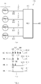
- FIG. 1 briefly shows the configuration of a plurality of battery racks 100 to 140 in the ESS.
- the ESS includes a plurality of battery racks.
- Each battery rack includes a plurality of battery modules connected in series and/or parallel.
- Each battery module is monitored and controlled by each lower-level BMS.
- FIG. 2 is a side view of a battery rack briefly showing the installation state of an upper-level BMS (BMC 10) and a lower-level BMS (CMC 22) according to an embodiment of the present invention.
- the lower-level BMS is included in the battery module
- the upper-level BMS that monitors and controls the entire battery rack status based on the information obtained from the lower-level BMS is illustrated as being included in the battery power unit (BPU), but this is illustrative and not restrictive.
- At least one of battery module mounting parts 50-1 to 50-n is formed in the battery rack, and rail parts 30-1 to 30-n are provided below the battery module mounting parts 50-1 to 50-n, so that when each of the battery module 20-1 to 20-n is inserted into the battery module mounting parts 50-1 to 50-n, it is stably fitted with the help of the rail parts 30-1 to 30-n.
- Pressure generation units 34-1 to 34-n are provided in a predetermined area of the rail parts 30-1 to 30-n, and at the bottom of the battery modules 20-1 to 20-n, sensors 23-1 to 23-n are provided to detect the pressure exerted by the pressure generation units 34-1 to 34-n, and when battery modules 20-1 to 20-n are properly inserted and installed, these sensors 23-1 to 23-n are placed in a position to detect pressure applied from the pressure generation units 34-1 to 34-n in contact with the pressure generation units 34-1 to 34-n.
- the sensors 23-1 to 23-n may be pressure sensors that output a predetermined pressure value according to pressure detection by changing the resistance according to the pressure applied by the pressure generation units 34-1 to 34-n, and the pressure generation units 34-1 to 34-n may be provided in different sizes within each battery module mounting parts 50-1 to 50-n, as shown in FIG. 2 .
- the sensors 23-1 to 23-n will output a pressure value of a size that can be associated with the battery module mounting parts 50-1 to 50-n, so that this pressure value allows identification of which battery mounting parts 50-1 to 50-n the battery modules 20-1 to 20-n are inserted into.
- the sensors 23-1 to 23-n may utilize a force sensitive resistor (FRS) or the like.
- a configuration example of the pressure detection unit 230 including the pressure generation units 34-1 to 34-n and the sensors 23-1 to 23-n will be described with reference to FIGS. 3 to 5 below.
- the battery modules 20-1 to 20-n, the CMC 22-1 to 22-n, the sensors 23-1 to 23-n, the rail parts 30-1 to 30-n, the pressure generation unit formation areas 32-1 to 32-n, the pressure generation units 34-1 to 34-n, and the battery module mounting parts 50-1 to 50-n, shown in FIG. 2 are briefly described as the battery module 20, the CMC 22, the sensor 23, the rail part 30, the pressure generation unit formation area 32, the pressure generation unit 34, and battery module mounting parts 50 except the case where it is necessary to specify each battery module in the battery rack.
- the function of each component a portion directly related to the automatic IP assignment function of the battery module according to an embodiment of the present invention will be mainly described.
- the BMC 12 of the BPU 10 shown in FIG. 2 communicates wirelessly with the CMC 22 of the battery module 20 to monitor and control the state of the entire battery module.
- the BMC 12 manages a unique ID for identifying each CMC 22 for wireless communication with each CMC 22. And, especially in the embodiments of the present invention, when a pressure detection signal including a pressure value is received from each CMC 22, based on the pressure value, the BMC 12 performs a function of automatically assigning an ID in connection with the installation location of the battery module 20 equipped with the CMC 22.
- FIG. 3 is a main block diagram of the CMC 22 according to an embodiment of the present invention
- FIG. 4(a) is an example of a configuration of the pressure detection unit shown in FIG. 3
- FIG. 4(b) is a view showing an example of a configuration of a pressure generation unit provided in a battery rack.
- the CMC 22 includes a wireless communication unit 21 for transmitting and receiving signals with the wireless communication unit 14 of the BMC 12 (see FIG. 6 ) in a wireless communication method such as Wi-Fi, ZigBee, or Bluetooth, a control unit 24 for transmitting a pressure detection signal to the BMC 12 through the wireless communication units 14 and 21 to perform a series of control operations for automatically assigning an ID from the BMC 12, and an ID storage unit 25 for registering and setting the ID assigned by the BMC 12 under the control of the control unit 24 and manages it.
- a wireless communication unit 21 for transmitting and receiving signals with the wireless communication unit 14 of the BMC 12 (see FIG. 6 ) in a wireless communication method such as Wi-Fi, ZigBee, or Bluetooth
- a control unit 24 for transmitting a pressure detection signal to the BMC 12 through the wireless communication units 14 and 21 to perform a series of control operations for automatically assigning an ID from the BMC 12, and an ID storage unit 25 for registering and setting the ID assigned by the BMC 12 under the control of the
- the CMC 22 may additionally include a module position automatic adjustment unit 26 for adjusting the position of the battery module 20 through the rail part 30 under the control of the control unit 24 according to the position adjustment command transmitted from the BMC 12 when recognition of the battery module has failed, and a notification unit 28 for warning a failure of the recognition of the battery module 20 under the control of the control unit 24 according to the position adjustment command.
- the notification unit 28 may employ a buzzer or an announce device, a warning lamp, or the like, capable of giving a visual or audible warning.
- the pressure detection unit 230 is provided on a predetermined surface part of the battery module 20, for example, a bottom part, as shown in FIG. 2 , and includes the sensor 23, for example, a pressure sensor in which the resistance value is changed by the pressure applied by the pressure generation unit 34 of the rail part 30, and outputs the pressure detection signal corresponding to the corresponding resistance value to the control unit 24.
- the pressure detection unit 230 may be configured as shown in FIG. 4(a) or FIG. 5(a) .
- the pressure detection unit 230 is provided with the sensor 23 which is a pressure sensor whose resistance value varies according to an area to which pressure is applied by the pressure generation unit 34, and the analog value outputted according to the resistance value of the pressure sensor is inputted to the A/D converter through the ADC terminal and outputted as a digital value.
- the pressure generation unit 34 is preferably configured as shown in FIG. 4(b) .
- the pressure generation unit formation area 32 is formed in the rail part 3 provided in each battery module mounting parts 50, for example, in a concave shape, and in order to apply a specific pressure to the sensor 23 so as to specify the installation position of the battery module in connection with each battery module mounting parts 50 in the pressure generation unit formation area 32, different sizes of the pressure generation units 34-1 to 34-4 are formed for the respective battery module mounting parts 50-1 to 50-4.
- Nos. 1, 2, 3, and 4 described on the left side of FIG. 4(b) indicate the numbers of the battery module mounting parts 50, and as shown in the same drawing, it is preferable that a pressure generation unit 34 of a different size is provided for each battery module mounting parts 50.
- the pressure detection unit 230 when the battery module 20 is inserted into the battery module mounting parts 50, the pressure detection unit 230 outputs a pressure value corresponding to the pressure applied by the area of each size of the pressure generation units 34-1 to 34-4. This pressure value will preferably vary depending on the battery module mounting parts 50 into which the battery module 20 is inserted.
- the sensor 23 is provided in the bottom part of the battery module 20, but in order to detect the pressure of a plurality of points applied by the plurality of pressure generation units 341 to 344 formed as shown in FIG. 5(b) , a plurality of sensors 1 to 4 may be configured in positions corresponding to the positions of the respective pressure generation unit 341 to 344.
- the sensor 1 to sensor 4 may be piezo sensors.
- the number of the sensors 1 to 4 may vary depending on the number of pressure generation units, and the number of pressure generation units may be determined according to the number of battery module mounting parts 50. When it is composed of four as shown in FIG. 5(b) , it is possible to correspond to the binary number 1000 (No.
- FIG. 5(b) in a structure in which pressure generation units 341 to 344 can be formed at 4 points, when all pressure generation units 341 to 344 are formed at 4 points, the pressure generation units 341 to 344 are sensed by the sensors 1 to 4, and the corresponding current value is applied to the MUX 220, so that the pressure value corresponding to '1111' is outputted from the MUX 220 and is identified as '15'.
- the pressure generation units 341 and 343 are sensed by the sensors 1 and 3, and corresponding current values are applied to the MUX 220, so that the pressure value corresponding to '1010' is outputted from the MUX 220 and is identified as '5'. If the pressure generation units 341 and 342 are formed at 4 points, the pressure generation units 341 and 342 are sensed by the sensors 1 and 2, and corresponding current values are applied to the MUX 220, so that the pressure value corresponding to '1100' is outputted from the MUX 220 and is identified as '3'.
- the pressure generation units 341 is sensed by the sensor 1, and corresponding current values are applied to the MUX 220, so that the pressure value corresponding to '1000' is outputted from the MUX 220 and is identified as '1' .
- the position of the battery module 20 to be inserted into the battery module mounting part 50 can be easily identified.
- the BMC 12 includes a wireless communication unit 14 that communicates wirelessly with the CMC 22, a pressure value extraction unit 16 that extracts the pressure value from the pressure detection signal transmitted from the CMC 22 and transmits it to the control unit 13, an ID information storage unit 18 that stores a reference pressure value for identifying a battery module that is inserted and mounted in each battery module mounting parts 50 of a battery rack and automatically assigned ID information associated with the reference pressure value, a control unit 13 that queries the reference input value from the ID information storage unit 18 by using the pressure value extracted by the pressure value extraction unit 16 and searches for an ID stored in association with the reference input value and applies it to the ID assignment unit 19, and the ID assignment unit 19 that automatically assigns and registers an ID for the CMC 22 transmitting the pressure detection signal using the searched ID and transmits the automatically assigned ID to the CMC 22 through the wireless communication unit 14.
- the reference input value stored in the ID information storage unit 18 is stored in correspondence with each battery module mounting parts 50, and the reference input value is preferably determined in relation to the pressure generation
- the resistance value is changed due to the pressure applied by the pressure generation unit 34, so that a pressure value corresponding to the pressure is generated, and the pressure value is transmitted to the control unit 24 of the CMC 22.
- the control unit 24 generates a pressure detection signal including the pressure value (S2), and transmits it to the BMC 12 through the wireless communication unit 21 (S4).
- the pressure value extraction unit 16 extracts the pressure value from the received pressure detection signal and transmits it to the control unit 13 (S8).
- the control unit 13 searches for ID information from the ID information storage unit 18 using the extracted pressure value and transmits it to the ID assignment unit 19 (S10).
- the control unit 13 searches for a reference pressure value corresponding to the extracted pressure value from the ID information storage unit 18, thereby searching for stored ID information associated with the reference pressure value.
- the ID assignment unit 19 assigns the searched ID to the battery module 20 that has transmitted the corresponding pressure detection signal under the control of the control unit 13 (S12), and wirelessly transmits the ID assignment information to the battery module 20 through the wireless communication unit 14 (S14).
- the process of storing it in the ID storage unit 25 and registering and setting it as its own ID is completed (S20).
- the CMC 22 of the battery module 20 that has completed the above-described series of processes notifies the completion of ID setting to the BPU 10 and ends the automatic ID assignment procedure (S22).
- the BMC 12 of the BPU 10 notified of the completion of ID setting transmitted from the battery module 20 also ends a series of automatic ID assignment procedures.
- the resistance value is changed due to the pressure applied by the pressure generation unit 34, so that a pressure value corresponding to the pressure is generated, and the pressure value is transmitted to the control unit 24 of the CMC 22.
- the control unit 24 generates a pressure detection signal including a pressure value (S2). It is transmitted to the BMC 12 through the wireless communication unit 21 (S4).
- the pressure value extraction unit 16 extracts the pressure value from the received pressure detection signal and transmits it to the control unit 13 (S8).
- the control unit 13 searches for the reference pressure value corresponding to the extracted pressure value from the ID information storage unit 18 to search for the stored ID information associated with the reference pressure value (S10). Subsequently, if the control unit 13 succeeds in retrieving the ID information (YES in S30), under the control of the control unit 13, the ID assignment unit 19 assigns the searched ID to the battery module 20 that has transmitted the corresponding pressure detection signal (S12), and then, wirelessly transmits ID assignment information to the battery module 20 through the wireless communication unit 14 (S14).
- the process of storing it in the ID storage unit 25 and registering and setting it as its own ID is completed (S20).
- the CMC 22 of the battery module 20 that has completed the above-described series of processes notifies the completion of ID setting to the BMC 12 and ends the automatic ID assignment procedure (S22).
- the BMC 12 notified of the completion of ID setting transmitted from the battery module 20 also ends a series of automatic ID assignment procedures.
- the control unit 13 determines this as a module recognition failure, notifies the battery module 20 of the module recognition failure, and transmits a position adjustment command for the corresponding module (S32).
- the pressure value does not fall within a predetermined range of the reference pressure value, this may be determined as the module recognition failure.
- the control unit 24 of the battery module receiving the position adjustment command from the BMC 12 controls the module position automatic adjustment unit 26 to adjust the position of the corresponding battery module 20 through the rail part 30 (S34), and then, proceeds to operation S2 and performs the process from operation S2 to operation S10 again.
- the control unit 24 that has received the position adjustment command may alert the battery module 20 of the recognition failure through the notification unit 28.
- the battery module whose position is automatically adjusted through operation S34 is moved to the correct position, and the pressure value detected by the pressure detection unit 230 falls within a predetermined range of the reference input value stored in the ID information storage unit 18, so that it is repeatedly performed until it is determined in S30 that the ID information search is successful.
Landscapes
- Engineering & Computer Science (AREA)
- Chemical & Material Sciences (AREA)
- Chemical Kinetics & Catalysis (AREA)
- Electrochemistry (AREA)
- General Chemical & Material Sciences (AREA)
- Manufacturing & Machinery (AREA)
- Microelectronics & Electronic Packaging (AREA)
- Computer Networks & Wireless Communication (AREA)
- Battery Mounting, Suspending (AREA)
- Measuring Fluid Pressure (AREA)
- Charge And Discharge Circuits For Batteries Or The Like (AREA)
- Secondary Cells (AREA)
Abstract
Description
- The present invention claims the benefit of priority based on
Korean Patent Application No. 10-2019-0095019 filed on August 5, 2019 - The present invention relates to a system in which an upper-level BMS automatically assigns an ID to a lower-level BMS in the same battery rack.
- Recently, research and development on secondary batteries have been actively conducted. Here, the secondary batteries, as batteries that can be charged and discharged, mean that they include conventional Ni/Cd batteries and Ni/MH batteries, and recent lithium ion batteries. Among the secondary batteries, the lithium ion battery has an advantage that the energy density is much higher than that of the conventional Ni/Cd battery and Ni/MH battery, and further, the lithium ion battery can be manufactured with a tendency of a small size so that it is used as a power source for a mobile apparatus. In addition, the usage range of the lithium ion battery extends as a power source for electric vehicles, so that the lithium ion battery attracts attention as a next generation energy storage medium.
- In addition, a secondary battery is generally used as a battery pack including a battery module in which a plurality of battery cells are connected in series and/or in parallel. And, a state and an operation of a battery pack are managed and controlled by a battery management system (BMS).
- A plurality of battery modules are connected in series/parallel to form a battery rack, and a plurality of battery racks are connected in parallel to form a battery bank. Such a battery bank can be used as an energy storage system (ESS). Each battery module is monitored and controlled by the corresponding lower-level BMS. The upper-level BMS, which is the top-level controller in each battery rack, monitors and controls each lower-level BMS, and monitors and controls the entire battery rack status based on information obtained from the lower-level BMS.
- At this time, when the lower-level BMS and the upper-level BMS of multiple battery racks communicate with each other wirelessly in the same space, the signal may be transmitted to a battery rack other than the corresponding battery rack. Therefore, after the initial installation of the ESS, each upper-level BMS automatically identifies the lower-level BMS placed in the same battery rack, so that there is a problem that it is difficult to assign an ID to the lower-level BMS.
- An object of the present invention is to automatically assign an ID of a lower-level BMS disposed in a corresponding battery rack by an upper-level BMS disposed in each battery rack in an ESS including a plurality of battery racks.
- According to an embodiment of the present invention, a battery module wirelessly communicates with an upper-level BMS and is inserted into at least one battery module mounting part formed in a battery rack, and includes: a pressure detection unit provided on a predetermined surface part of the battery module and configured to detect a pressure applied to the predetermined surface part and output a pressure value; a wireless communication unit configured to transmit a pressure detection signal including the pressure value to the upper-level BMS through wireless communication; and when ID information automatically assigned from the upper-level BMS is received, a control unit configured to set and register the received ID information as its own ID.
- In the battery module according to an embodiment of the present invention, the pressure detection unit includes a pressure sensor that outputs different pressure values according to an area to which pressure is applied.
- In the battery module according to an embodiment of the present invention, the pressure detection unit includes a plurality of pressure sensing means for outputting pressure values for a plurality of points to which pressure is applied, and a signal processing unit for outputting a series of digital signals by muxing the outputs from the plurality of pressure sensing means.
- In the battery module according to an embodiment of the present invention, the predetermined surface part receives pressure from a pressure generation unit provided corresponding to a portion where the predetermined surface part contacts the battery module mounting part when the battery module is inserted and mounted in the battery module mounting part, wherein the pressure generation unit is provided with a different size or number for each of the battery module mounting part to apply a different pressure to each battery module.
- In the battery module according to an embodiment of the present invention, the predetermined surface part is a bottom part of the battery module.
- According to an embodiment of the present invention, an upper-level BMS wirelessly communicates with at least one battery module mounted in a battery rack, and includes: a control unit configured to identify a battery module that has transmitted a pressure detection signal including a pressure value, and automatically assign an ID to the identified battery module based on a reference pressure value corresponding to a battery module mounting part into which each of the battery modules are inserted; an ID information storage unit configured to store a reference pressure value for identifying the battery module and ID information that is automatically assigned in association with the reference pressure values; and an ID assignment information storage unit configured to store ID information that is automatically assigned to the battery module identified by the control unit.
- In the upper-level BMS according to an embodiment of the present invention, the control unit identifies the battery module based on the reference pressure value stored in the ID information storage unit, and according to a result of comparing the pressure value included in the pressure detection signal and the reference pressure value stored in the ID information storage unit, if the pressure value does not fall within a predetermined range of the reference pressure value, determines that the identification of the battery module has failed, and notifies the battery module of ID assignment failure.
- In the upper-level BMS according to an embodiment of the present invention, when the identification of the battery module fails, the control unit transmits a position adjustment command to the battery module, and terminates the ID assignment procedure for the battery module.
- In the upper-level BMS according to an embodiment of the present invention, the reference pressure value is a value corresponding to a reference value for pressure applied by a pressure generation unit provided in the battery module mounting part, wherein in order to identify the battery module inserted into the battery module mounting part, the reference value is a different value for each of the pressure generation units provided in the battery module mounting part.
- According to another embodiment of the present invention, an automatic ID assignment system of a battery module includes: a batter module including: a pressure detection unit provided on a predetermined surface part of a battery module and configured to detect a pressure applied to the predetermined surface part and output a pressure value; a wireless communication unit configured to transmit a pressure detection signal including the pressure value to the upper-level BMS through wireless communication; and when ID information automatically assigned from the upper-level BMS is received, a first control unit configured to set and register the received ID information as its own ID and inserted into a battery module mounting part formed in at least one battery rack; and an upper-level BMS configured to wirelessly communicate with the battery module and including: a second control unit configured to identify a battery module that has transmitted a pressure detection signal including a pressure value, and automatically assign an ID to the identified battery module based on a reference pressure value corresponding to a battery module mounting part into which each of the battery modules are inserted; an ID information storage unit configured to store a reference pressure value for identifying the battery module and ID information that is automatically assigned in association with the reference pressure values; and an ID assignment information storage unit configured to store ID information that is automatically assigned to the battery module identified by the control unit.
- In the automatic ID assignment system according another embodiment of the present invention, the pressure detection unit includes a pressure sensor that outputs different pressure values according to an area to which pressure is applied.
- In the automatic ID assignment system according another embodiment of the present invention, the pressure detection unit includes a plurality of pressure sensing means for outputting pressure values for a plurality of points to which pressure is applied, and a signal processing unit for outputting a series of digital signals by muxing the outputs from the plurality of pressure sensing means.
- In the automatic ID assignment system according another embodiment of the present invention, the predetermined surface part receives pressure from a pressure generation unit provided corresponding to a portion where the predetermined surface part contacts the battery module mounting part when the battery module is inserted and mounted in the battery module mounting part, thereby outputting a pressure value corresponding thereto.
- In the automatic ID assignment system according another embodiment of the present invention, the second control unit identifies the battery module based on the reference pressure value stored in the ID information storage unit, and according to a result of comparing the pressure value included in the pressure detection signal and the reference pressure value stored in the ID information storage unit, if the pressure value does not fall within a predetermined range of the reference pressure value, determines that the identification of the battery module has failed, and notifies the battery module of ID assignment failure.
- In the automatic ID assignment system according another embodiment of the present invention, when the identification of the battery module fails, the second control unit transmits a position adjustment command to the battery module, and terminates the ID assignment procedure for the battery module.
- The automatic ID allocation method of the battery module according to another embodiment of the present invention includes detecting a pressure applied to a predetermined surface portion, and transmitting a pressure detection signal including a pressure value corresponding to the pressure detected through wireless communication to an upper-level BMS in at least one battery module inserted into at least one battery module mounting part formed in the battery rack; identifying a battery module that has transmitted a pressure detection signal including a pressure value, and automatically assigning an ID to the identified battery module based on a reference pressure value corresponding to a battery module mounting part into which each of the battery modules are inserted in the upper-level BMS; storing ID information for the automatically assigned and identified battery module, and wirelessly communicating the automatically assigned ID information to the battery module; and setting and registering its own ID based on ID information automatically allocated from the upper-level BMS, and ending setting the ID in the battery module.
- According to embodiments of the invention, the upper-level BMS disposed in each battery rack in the ESS including a plurality of battery racks automatically assigns the ID of the lower-level BMS arranged in the corresponding battery rack, thereby enabling efficient management of the ESS.
-
-
FIG. 1 schematically illustrates a configuration of a plurality of battery racks in an ESS in relation to an embodiment of the present invention. -
FIG. 2 is a side view of a battery rack briefly showing the installation state of an upper-level BMS (BMC) and a lower-level BMS (CMC) according to an embodiment of the present invention. -
FIG. 3 is a main block diagram of a lower-level BMS according to an embodiment of the present invention. -
FIG. 4(a) is an example of a configuration of the pressure detection unit shown inFIG. 3 , andFIG. 4(b) is a view showing an example of a configuration of a pressure generation unit provided in a battery rack. -
FIG. 5(a) is another example of a configuration of the pressure detection unit shown inFIG. 3 , andFIG. 5(b) is a view showing another example of a configuration of a pressure generation unit provided in a battery rack. -
FIG. 6 is a main block diagram of an upper-level BMS according to an embodiment of the present invention. -
FIG. 7 is a flowchart illustrating an automatic ID allocation method of a battery module according to an embodiment of the present invention. -
FIG. 8 is a flowchart illustrating an automatic ID allocation method of a battery module according to another embodiment of the present invention. - Hereinafter, various embodiments of the present invention are disclosed with reference to the accompanying drawings. However, this is not intended to limit the invention to the specific embodiments, and it is to be understood that the invention includes various modifications, equivalents, and/or alternatives. With respect to the descriptions of the drawings, like reference numerals refer to like elements.
- Terms used in various embodiments of the present disclosure are used to describe specific embodiments of the present disclosure, and are not intended to limit the scope of other embodiments. The terms of a singular form may include plural forms unless they have a clearly different meaning in the context. Otherwise indicated herein, all the terms used herein, which include technical or scientific terms, may have the same meaning that is generally understood by a person skilled in the art. In general, the terms defined in the dictionary should be considered to have the same meaning as the contextual meaning of the related art, and, unless clearly defined herein, should not be understood as having an ideal or excessively formal meaning. In any cases, even the terms defined in this specification cannot be interpreted as excluding embodiments of the present invention.
- In addition, in describing the components of the embodiment of the present invention, terms such as first, second, A, B, (a), and (b) may be used. These terms are only to distinguish the components from other components, and the nature, sequence, or order of the components are not limited by the terms. In addition, when a component is described as being "connected to", "coupled to" or "linked to" another component, the components may be directly connected to or linked to each other but it should be understood that other components may be "connected", "coupled", or "linked" between each component.
-
FIG. 1 briefly shows the configuration of a plurality of battery racks 100 to 140 in the ESS. - The ESS includes a plurality of battery racks. Each battery rack includes a plurality of battery modules connected in series and/or parallel. Each battery module is monitored and controlled by each lower-level BMS.
- In this way, when a plurality of battery racks are included in one ESS, and wirelessly communicates between the upper-level BMS and the lower-level BMS in the battery rack, since wireless communication can be performed between the upper-level BMS in the battery rack and the lower-level BMS in the other battery rack, after the ESS is initially installed, it is difficult to identify the lower-level BMS where each upper-level BMS is located in the same battery rack. Therefore, in the related art, when initially installing the ESS, the installer had to manually input ID information to each lower-level BMS or install the modules in a predetermined order. In this case, there was a problem that a mistake may occur in the installation process, and it may take more time to install. An automatic ID assignment system and method for a battery module according to an embodiment of the present invention for solving this problem will be described later.
-
FIG. 2 is a side view of a battery rack briefly showing the installation state of an upper-level BMS (BMC 10) and a lower-level BMS (CMC 22) according to an embodiment of the present invention. In an embodiment of the present invention, the lower-level BMS is included in the battery module, and the upper-level BMS that monitors and controls the entire battery rack status based on the information obtained from the lower-level BMS is illustrated as being included in the battery power unit (BPU), but this is illustrative and not restrictive. - At least one of battery module mounting parts 50-1 to 50-n is formed in the battery rack, and rail parts 30-1 to 30-n are provided below the battery module mounting parts 50-1 to 50-n, so that when each of the battery module 20-1 to 20-n is inserted into the battery module mounting parts 50-1 to 50-n, it is stably fitted with the help of the rail parts 30-1 to 30-n.
- Pressure generation units 34-1 to 34-n are provided in a predetermined area of the rail parts 30-1 to 30-n, and at the bottom of the battery modules 20-1 to 20-n, sensors 23-1 to 23-n are provided to detect the pressure exerted by the pressure generation units 34-1 to 34-n, and when battery modules 20-1 to 20-n are properly inserted and installed, these sensors 23-1 to 23-n are placed in a position to detect pressure applied from the pressure generation units 34-1 to 34-n in contact with the pressure generation units 34-1 to 34-n.
- The sensors 23-1 to 23-n may be pressure sensors that output a predetermined pressure value according to pressure detection by changing the resistance according to the pressure applied by the pressure generation units 34-1 to 34-n, and the pressure generation units 34-1 to 34-n may be provided in different sizes within each battery module mounting parts 50-1 to 50-n, as shown in
FIG. 2 . In this case, since the pressure applied depends on the size of the pressure generation units 34-1 to 34-n, the sensors 23-1 to 23-n will output a pressure value of a size that can be associated with the battery module mounting parts 50-1 to 50-n, so that this pressure value allows identification of which battery mounting parts 50-1 to 50-n the battery modules 20-1 to 20-n are inserted into. The sensors 23-1 to 23-n may utilize a force sensitive resistor (FRS) or the like. - A configuration example of the
pressure detection unit 230 including the pressure generation units 34-1 to 34-n and the sensors 23-1 to 23-n will be described with reference toFIGS. 3 to 5 below. - In addition, the battery modules 20-1 to 20-n, the CMC 22-1 to 22-n, the sensors 23-1 to 23-n, the rail parts 30-1 to 30-n, the pressure generation unit formation areas 32-1 to 32-n, the pressure generation units 34-1 to 34-n, and the battery module mounting parts 50-1 to 50-n, shown in
FIG. 2 , are briefly described as the battery module 20, theCMC 22, thesensor 23, therail part 30, the pressure generationunit formation area 32, thepressure generation unit 34, and batterymodule mounting parts 50 except the case where it is necessary to specify each battery module in the battery rack. For the function of each component, a portion directly related to the automatic IP assignment function of the battery module according to an embodiment of the present invention will be mainly described. - Meanwhile, the
BMC 12 of theBPU 10 shown inFIG. 2 communicates wirelessly with theCMC 22 of the battery module 20 to monitor and control the state of the entire battery module. TheBMC 12 manages a unique ID for identifying eachCMC 22 for wireless communication with eachCMC 22. And, especially in the embodiments of the present invention, when a pressure detection signal including a pressure value is received from eachCMC 22, based on the pressure value, theBMC 12 performs a function of automatically assigning an ID in connection with the installation location of the battery module 20 equipped with theCMC 22. - Next,
FIG. 3 is a main block diagram of theCMC 22 according to an embodiment of the present invention,FIG. 4(a) is an example of a configuration of the pressure detection unit shown inFIG. 3 , andFIG. 4(b) is a view showing an example of a configuration of a pressure generation unit provided in a battery rack. - First, referring to
FIG. 3 , theCMC 22 includes awireless communication unit 21 for transmitting and receiving signals with thewireless communication unit 14 of the BMC 12 (seeFIG. 6 ) in a wireless communication method such as Wi-Fi, ZigBee, or Bluetooth, acontrol unit 24 for transmitting a pressure detection signal to theBMC 12 through thewireless communication units BMC 12, and anID storage unit 25 for registering and setting the ID assigned by theBMC 12 under the control of thecontrol unit 24 and manages it. In addition, theCMC 22 may additionally include a module positionautomatic adjustment unit 26 for adjusting the position of the battery module 20 through therail part 30 under the control of thecontrol unit 24 according to the position adjustment command transmitted from theBMC 12 when recognition of the battery module has failed, and anotification unit 28 for warning a failure of the recognition of the battery module 20 under the control of thecontrol unit 24 according to the position adjustment command. In an embodiment of the present invention, thenotification unit 28 may employ a buzzer or an announce device, a warning lamp, or the like, capable of giving a visual or audible warning. - Meanwhile, the
pressure detection unit 230 is provided on a predetermined surface part of the battery module 20, for example, a bottom part, as shown inFIG. 2 , and includes thesensor 23, for example, a pressure sensor in which the resistance value is changed by the pressure applied by thepressure generation unit 34 of therail part 30, and outputs the pressure detection signal corresponding to the corresponding resistance value to thecontrol unit 24. - The
pressure detection unit 230 may be configured as shown inFIG. 4(a) orFIG. 5(a) . - Referring to
FIG. 4(a) , thepressure detection unit 230 is provided with thesensor 23 which is a pressure sensor whose resistance value varies according to an area to which pressure is applied by thepressure generation unit 34, and the analog value outputted according to the resistance value of the pressure sensor is inputted to the A/D converter through the ADC terminal and outputted as a digital value. - In this case, the
pressure generation unit 34 is preferably configured as shown inFIG. 4(b) . - That is, the pressure generation
unit formation area 32 is formed in therail part 3 provided in each batterymodule mounting parts 50, for example, in a concave shape, and in order to apply a specific pressure to thesensor 23 so as to specify the installation position of the battery module in connection with each batterymodule mounting parts 50 in the pressure generationunit formation area 32, different sizes of the pressure generation units 34-1 to 34-4 are formed for the respective battery module mounting parts 50-1 to 50-4. Nos. 1, 2, 3, and 4 described on the left side ofFIG. 4(b) indicate the numbers of the batterymodule mounting parts 50, and as shown in the same drawing, it is preferable that apressure generation unit 34 of a different size is provided for each batterymodule mounting parts 50. - According to the configuration of
FIG. 4 , when the battery module 20 is inserted into the batterymodule mounting parts 50, thepressure detection unit 230 outputs a pressure value corresponding to the pressure applied by the area of each size of the pressure generation units 34-1 to 34-4. This pressure value will preferably vary depending on the batterymodule mounting parts 50 into which the battery module 20 is inserted. - Meanwhile, another configuration example of the
pressure detection unit 230 will be described with reference toFIG. 5(a) . - According to
FIG. 5(a) , as in the configuration example ofFIG. 4 , thesensor 23 is provided in the bottom part of the battery module 20, but in order to detect the pressure of a plurality of points applied by the plurality ofpressure generation units 341 to 344 formed as shown inFIG. 5(b) , a plurality ofsensors 1 to 4 may be configured in positions corresponding to the positions of the respectivepressure generation unit 341 to 344. Thesensor 1 tosensor 4 may be piezo sensors. The number of thesensors 1 to 4 may vary depending on the number of pressure generation units, and the number of pressure generation units may be determined according to the number of batterymodule mounting parts 50. When it is composed of four as shown inFIG. 5(b) , it is possible to correspond to the binary number 1000 (No. 1) to 1111 (No. 15), so that up to 15 (24-1) battery module mounting parts can be distinguished. Likewise, if fivepressure generation units 341 to 345 are formed in the pressure generationunit formation area 32, up to 31 (25-1) of batterymodule mounting parts 50 can be distinguished. Here, distinguishing the batterymodule mounting parts 50 may be used as synonymous with distinguishing the battery module. - According to
FIG. 5(b) , in a structure in whichpressure generation units 341 to 344 can be formed at 4 points, when allpressure generation units 341 to 344 are formed at 4 points, thepressure generation units 341 to 344 are sensed by thesensors 1 to 4, and the corresponding current value is applied to theMUX 220, so that the pressure value corresponding to '1111' is outputted from theMUX 220 and is identified as '15'. If thepressure generation units pressure generation units sensors MUX 220, so that the pressure value corresponding to '1010' is outputted from theMUX 220 and is identified as '5'. If thepressure generation units pressure generation units sensors MUX 220, so that the pressure value corresponding to '1100' is outputted from theMUX 220 and is identified as '3'. Then, if only thepressure generation unit 341 is formed at 4 points, thepressure generation units 341 is sensed by thesensor 1, and corresponding current values are applied to theMUX 220, so that the pressure value corresponding to '1000' is outputted from theMUX 220 and is identified as '1' . - Thus, according to the formation position of the
pressure generation unit 34, the position of the battery module 20 to be inserted into the batterymodule mounting part 50 can be easily identified. - Next, with reference to
FIG. 6 , the main configuration of theBMC 12 corresponding to the upper-level BMS according to an embodiment of the present invention will be described. - The
BMC 12 according to an embodiment of the present invention includes awireless communication unit 14 that communicates wirelessly with theCMC 22, a pressurevalue extraction unit 16 that extracts the pressure value from the pressure detection signal transmitted from theCMC 22 and transmits it to thecontrol unit 13, an IDinformation storage unit 18 that stores a reference pressure value for identifying a battery module that is inserted and mounted in each batterymodule mounting parts 50 of a battery rack and automatically assigned ID information associated with the reference pressure value, acontrol unit 13 that queries the reference input value from the IDinformation storage unit 18 by using the pressure value extracted by the pressurevalue extraction unit 16 and searches for an ID stored in association with the reference input value and applies it to theID assignment unit 19, and theID assignment unit 19 that automatically assigns and registers an ID for theCMC 22 transmitting the pressure detection signal using the searched ID and transmits the automatically assigned ID to theCMC 22 through thewireless communication unit 14. In addition, the reference input value stored in the IDinformation storage unit 18 is stored in correspondence with each batterymodule mounting parts 50, and the reference input value is preferably determined in relation to thepressure generation unit 34 provided in each batterymodule mounting parts 50. - Hereinafter, an automatic ID assignment method of a battery module according to an embodiment of the present invention will be described with reference to the flowchart shown in
FIG. 7 . - When the battery module 20 is inserted into the battery
module mounting parts 50 by an operator, in thesensor 23 of battery module 20, the resistance value is changed due to the pressure applied by thepressure generation unit 34, so that a pressure value corresponding to the pressure is generated, and the pressure value is transmitted to thecontrol unit 24 of theCMC 22. Thecontrol unit 24 generates a pressure detection signal including the pressure value (S2), and transmits it to theBMC 12 through the wireless communication unit 21 (S4). - In the
BMC 12, when the pressure detection signal is received through the wireless communication unit 14 (S6), the pressurevalue extraction unit 16 extracts the pressure value from the received pressure detection signal and transmits it to the control unit 13 (S8). - The
control unit 13 searches for ID information from the IDinformation storage unit 18 using the extracted pressure value and transmits it to the ID assignment unit 19 (S10). In operation S10, thecontrol unit 13 searches for a reference pressure value corresponding to the extracted pressure value from the IDinformation storage unit 18, thereby searching for stored ID information associated with the reference pressure value. - Subsequently, the
ID assignment unit 19 assigns the searched ID to the battery module 20 that has transmitted the corresponding pressure detection signal under the control of the control unit 13 (S12), and wirelessly transmits the ID assignment information to the battery module 20 through the wireless communication unit 14 (S14). - Subsequently, in the battery module 20, when ID assignment information is received through the wireless communication unit 21 (S16), after extracting the ID assigned to the battery module from the ID assignment information received by the
ID storage unit 25 under the control of the CMC 22 (S18), the process of storing it in theID storage unit 25 and registering and setting it as its own ID is completed (S20). TheCMC 22 of the battery module 20 that has completed the above-described series of processes notifies the completion of ID setting to theBPU 10 and ends the automatic ID assignment procedure (S22). - In addition, the
BMC 12 of theBPU 10 notified of the completion of ID setting transmitted from the battery module 20 also ends a series of automatic ID assignment procedures. - Hereinafter, an automatic ID allocation method of a battery module according to an embodiment of the present invention will be described with reference to the flowchart shown in
FIG. 8 . - When the battery module 20 is inserted into the battery
module mounting parts 50 by an operator, in thesensor 23 of battery module 20, the resistance value is changed due to the pressure applied by thepressure generation unit 34, so that a pressure value corresponding to the pressure is generated, and the pressure value is transmitted to thecontrol unit 24 of theCMC 22. Thecontrol unit 24 generates a pressure detection signal including a pressure value (S2). It is transmitted to theBMC 12 through the wireless communication unit 21 (S4). - In the
BMC 12, when the pressure detection signal is received through the wireless communication unit 14 (S6), the pressurevalue extraction unit 16 extracts the pressure value from the received pressure detection signal and transmits it to the control unit 13 (S8). - The
control unit 13 searches for the reference pressure value corresponding to the extracted pressure value from the IDinformation storage unit 18 to search for the stored ID information associated with the reference pressure value (S10). Subsequently, if thecontrol unit 13 succeeds in retrieving the ID information (YES in S30), under the control of thecontrol unit 13, theID assignment unit 19 assigns the searched ID to the battery module 20 that has transmitted the corresponding pressure detection signal (S12), and then, wirelessly transmits ID assignment information to the battery module 20 through the wireless communication unit 14 (S14). - Subsequently, in the battery module 20, when ID allocation information is received through the wireless communication unit 21 (S16), after extracting the ID assigned to the battery module from the ID allocation information received by the
ID storage unit 25 under the control of the CMC 22 (S18), the process of storing it in theID storage unit 25 and registering and setting it as its own ID is completed (S20). TheCMC 22 of the battery module 20 that has completed the above-described series of processes notifies the completion of ID setting to theBMC 12 and ends the automatic ID assignment procedure (S22). - In addition, the
BMC 12 notified of the completion of ID setting transmitted from the battery module 20 also ends a series of automatic ID assignment procedures. - Meanwhile, as a result of searching for the reference pressure value from the ID
information storage unit 18 using the extracted pressure value, if the search of the stored ID information associated with the reference pressure value fails (No in S30), thecontrol unit 13 determines this as a module recognition failure, notifies the battery module 20 of the module recognition failure, and transmits a position adjustment command for the corresponding module (S32). Here, if the pressure value does not fall within a predetermined range of the reference pressure value, this may be determined as the module recognition failure. - The
control unit 24 of the battery module receiving the position adjustment command from theBMC 12 controls the module positionautomatic adjustment unit 26 to adjust the position of the corresponding battery module 20 through the rail part 30 (S34), and then, proceeds to operation S2 and performs the process from operation S2 to operation S10 again. Optionally, thecontrol unit 24 that has received the position adjustment command may alert the battery module 20 of the recognition failure through thenotification unit 28. - In operation S30 to operation S34, the battery module whose position is automatically adjusted through operation S34 is moved to the correct position, and the pressure value detected by the
pressure detection unit 230 falls within a predetermined range of the reference input value stored in the IDinformation storage unit 18, so that it is repeatedly performed until it is determined in S30 that the ID information search is successful. - Reference herein to 'one embodiment' of the principles of the present invention and various modifications of such expressions means that, in relation to this embodiment, the specific features, structures, characteristics, and the like are included in at least one embodiment of the principles of the present invention. Thus, the expression 'in one embodiment' and any other modifications disclosed throughout the specification are not necessarily all referring to the same embodiment.
- All the embodiments and conditional examples disclosed in this specification are described to intend to help those skilled in the art to understand the principles and concepts of the present invention, so that it will be understood by those skilled in the art that various changes in form and details may be made therein without departing from the spirit and scope of the present invention. Therefore, the disclosed embodiments should be considered in descriptive sense only not in limited perspective sense. The scope of the invention is defined not by the detailed description of the invention but by the appended claims, and all differences within the scope will be construed as being included in the present invention.
Claims (15)
- A battery module that wirelessly communicates with an upper-level BMS and is inserted into at least one battery module mounting part formed in a battery rack, the battery module comprising:a pressure detection unit provided on a predetermined surface part of the battery module and configured to detect a pressure applied to the predetermined surface part and output a pressure value;a wireless communication unit configured to transmit a pressure detection signal including the pressure value to the upper-level BMS through wireless communication; anda control unit configured to set and register a received ID information as its own ID when the ID information automatically assigned from the upper-level BMS is received.
- The battery module of claim 1, wherein the pressure detection unit comprises a pressure sensor that outputs different pressure values according to an area to which pressure is applied.
- The battery module of claim 1, wherein the pressure detection unit comprises a plurality of pressure sensing means for outputting pressure values for a plurality of points to which pressure is applied, and
a signal processing unit for outputting a series of digital signals by muxing the outputs from the plurality of pressure sensing means. - The battery module of claim 2 or 3, wherein the predetermined surface part receives pressure from a pressure generation unit provided corresponding to a portion where the predetermined surface part contacts the battery module mounting part when the battery module is inserted and mounted in the battery module mounting part,
wherein the pressure generation unit is provided with a different size or number for each of the battery module mounting part to apply a different pressure to each battery module. - The battery module of claim 4, wherein the predetermined surface part is a bottom part of the battery module.
- An upper-level BMS that wirelessly communicates with at least one battery module mounted in a battery rack, the upper-level BMS comprising:a control unit configured to identify a battery module that has transmitted a pressure detection signal including a pressure value, and automatically assign an ID to the identified battery module based on a reference pressure value corresponding to a battery module mounting part into which each of the battery modules are inserted;an ID information storage unit configured to store a reference pressure value for identifying the battery module and ID information that is automatically assigned in association with the reference pressure values; andan ID assignment information storage unit configured to store ID information that is automatically assigned to the battery module identified by the control unit.
- The upper-level BMS of claim 6, wherein the control unit identifies the battery module based on the reference pressure value stored in the ID information storage unit, and according to a result of comparing the pressure value included in the pressure detection signal and the reference pressure value stored in the ID information storage unit, if the pressure value does not fall within a predetermined range of the reference pressure value, determines that the identification of the battery module has failed, and notifies the battery module of ID assignment failure.
- The upper-level BMS of claim 6 or 7, wherein when the identification of the battery module fails, the control unit transmits a position adjustment command to the battery module, and terminates the ID assignment procedure for the battery module.
- The upper-level BMS of claim 6 or 7, wherein the reference pressure value is a value corresponding to a reference value for pressure applied by a pressure generation unit provided in the battery module mounting part,
wherein in order to identify the battery module inserted into the battery module mounting part, the reference value is a different value for each of the pressure generation units provided in the battery module mounting part. - An automatic ID assignment system of a battery module comprising:a batter module including: a pressure detection unit provided on a predetermined surface part of a battery module and configured to detect a pressure applied to the predetermined surface part and output a pressure value; a wireless communication unit configured to transmit a pressure detection signal including the pressure value to the upper-level BMS through wireless communication; and when ID information automatically assigned from the upper-level BMS is received, a first control unit configured to set and register the received ID information as its own ID and inserted into a battery module mounting part formed in at least one battery rack; andan upper-level BMS configured to wirelessly communicate with the battery module and including: a second control unit configured to identify a battery module that has transmitted a pressure detection signal including a pressure value, and automatically assign an ID to the identified battery module based on a reference pressure value corresponding to a battery module mounting part into which each of the battery modules are inserted; an ID information storage unit configured to store a reference pressure value for identifying the battery module and ID information that is automatically assigned in association with the reference pressure values; and an ID assignment information storage unit configured to store ID information that is automatically assigned to the battery module identified by the control unit.
- The automatic ID assignment system of claim 10, wherein the pressure detection unit comprises a pressure sensor that outputs different pressure values according to an area to which pressure is applied.
- The automatic ID assignment system of claim 10, wherein the pressure detection unit comprises a plurality of pressure sensing means for outputting pressure values for a plurality of points to which pressure is applied, and
a signal processing unit for outputting a series of digital signals by muxing the outputs from the plurality of pressure sensing means. - The automatic ID assignment system of claim 11 or 12, wherein the predetermined surface part receives pressure from a pressure generation unit provided corresponding to a portion where the predetermined surface part contacts the battery module mounting part when the battery module is inserted and mounted in the battery module mounting part, thereby outputting a pressure value corresponding thereto.
- The automatic ID assignment system of claim 10, wherein the second control unit identifies the battery module based on the reference pressure value stored in the ID information storage unit, and according to a result of comparing the pressure value included in the pressure detection signal and the reference pressure value stored in the ID information storage unit, if the pressure value does not fall within a predetermined range of the reference pressure value, determines that the identification of the battery module has failed, and notifies the battery module of ID assignment failure.
- The automatic ID assignment system of claim 10 or 11, wherein when the identification of the battery module fails, the second control unit transmits a position adjustment command to the battery module, and terminates the ID assignment procedure for the battery module.
Applications Claiming Priority (2)
| Application Number | Priority Date | Filing Date | Title |
|---|---|---|---|
| KR1020190095019A KR102705897B1 (en) | 2019-08-05 | 2019-08-05 | Automatic id assignment system and method for battery module |
| PCT/KR2020/008559 WO2021025297A1 (en) | 2019-08-05 | 2020-07-01 | Automatic id allocation system and method for battery module |
Publications (3)
| Publication Number | Publication Date |
|---|---|
| EP3993132A1 true EP3993132A1 (en) | 2022-05-04 |
| EP3993132A4 EP3993132A4 (en) | 2022-10-19 |
| EP3993132B1 EP3993132B1 (en) | 2023-11-08 |
Family
ID=74503670
Family Applications (1)
| Application Number | Title | Priority Date | Filing Date |
|---|---|---|---|
| EP20850843.2A Active EP3993132B1 (en) | 2019-08-05 | 2020-07-01 | Automatic id allocation system and method for battery module |
Country Status (10)
| Country | Link |
|---|---|
| US (1) | US12327843B2 (en) |
| EP (1) | EP3993132B1 (en) |
| JP (1) | JP7366482B2 (en) |
| KR (1) | KR102705897B1 (en) |
| CN (1) | CN114175351B (en) |
| AU (1) | AU2020326051B2 (en) |
| ES (1) | ES2962929T3 (en) |
| HU (1) | HUE064589T2 (en) |
| PL (1) | PL3993132T3 (en) |
| WO (1) | WO2021025297A1 (en) |
Families Citing this family (3)
| Publication number | Priority date | Publication date | Assignee | Title |
|---|---|---|---|---|
| EP3994894B1 (en) * | 2019-07-02 | 2024-11-13 | Wärtsilä Finland Oy | Determination of a configuration of a battery pack |
| DE102023112150A1 (en) * | 2023-05-09 | 2024-11-14 | Man Truck & Bus Se | Electrical energy storage device for a commercial vehicle and commercial vehicle with such an electrical energy storage device |
| CN116360377B (en) * | 2023-06-01 | 2023-08-29 | 深圳和润达科技有限公司 | Data processing method for battery cell formation component capacity and distributed control system |
Family Cites Families (33)
| Publication number | Priority date | Publication date | Assignee | Title |
|---|---|---|---|---|
| US6446680B1 (en) * | 1998-09-30 | 2002-09-10 | Creative Edge Design Group, Ltd. | System for processing and packaging milk and other beverages |
| US8765276B2 (en) * | 2009-07-06 | 2014-07-01 | Tesla Motors, Inc. | Common mode voltage enumeration in a battery pack |
| KR101156342B1 (en) | 2009-08-03 | 2012-06-13 | 삼성에스디아이 주식회사 | Battery id setting system and driving method thereof |
| US9446679B2 (en) * | 2011-03-28 | 2016-09-20 | Sanyo Electric Co., Ltd. | Battery system, electric vehicle, mobile unit, electric power storage device and power supply device |
| US9696383B2 (en) | 2011-10-07 | 2017-07-04 | Hitachi Automotive Systems, Ltd. | Battery monitoring system, host controller, and battery monitoring device |
| KR101542094B1 (en) | 2011-11-16 | 2015-08-06 | 주식회사 엘지화학 | Battery management system and battery pack protection apparatus including the same |
| KR101597317B1 (en) | 2011-12-01 | 2016-02-24 | 주식회사 엘지화학 | Battery pack system and battery structure for the same |
| KR101539689B1 (en) | 2012-02-20 | 2015-07-27 | 주식회사 엘지화학 | System and method for identifier allowcation of multi-bms |
| KR101433478B1 (en) * | 2012-12-17 | 2014-09-18 | 넥스콘 테크놀러지 주식회사 | A Method of Auto CAN ID Setting for Energy Storage System Slave Battery Management System |
| KR20150019902A (en) | 2013-08-16 | 2015-02-25 | 삼성에스디아이 주식회사 | Battery system, method for controlling battery system and energy storage system including the same |
| KR20150033188A (en) | 2013-09-23 | 2015-04-01 | 삼성에스디아이 주식회사 | Battery system, method for controlling battery system and energy storage system including the same |
| WO2015181866A1 (en) | 2014-05-26 | 2015-12-03 | 株式会社日立製作所 | Battery system |
| KR102273646B1 (en) | 2014-10-27 | 2021-07-06 | 삼성에스디아이 주식회사 | Energy storage system and id installing mathod to battery tray of the same |
| CN104638718B (en) * | 2015-01-06 | 2017-03-29 | 浙江超威创元实业有限公司 | A kind of battery of electric vehicle intelligent management system and method |
| JP6578868B2 (en) * | 2015-10-05 | 2019-09-25 | 株式会社豊田自動織機 | Method for manufacturing power storage device |
| KR102101909B1 (en) * | 2015-11-02 | 2020-04-17 | 주식회사 엘지화학 | Apparatus and method for battery id assignment |
| US10794957B2 (en) * | 2015-12-17 | 2020-10-06 | Lg Chem, Ltd. | Battery module and cell configuration recognition system for ID assignment |
| KR102123671B1 (en) | 2016-02-22 | 2020-06-16 | 주식회사 엘지화학 | Method allocating identifier for battery management system |
| JP6654518B2 (en) | 2016-06-30 | 2020-02-26 | 株式会社エンビジョンAescエナジーデバイス | Information processing system, battery module, control method, and program |
| CN106114275B (en) * | 2016-08-23 | 2019-11-08 | 新能瑞驰(北京)能源技术有限公司 | A kind of intelligent power battery pack and new-energy automobile |
| KR20180036863A (en) * | 2016-09-30 | 2018-04-10 | 현대자동차주식회사 | Battery unit |
| KR101969763B1 (en) | 2016-11-03 | 2019-04-17 | 에스케이이노베이션 주식회사 | Battery management system and method for assigning communication id |
| EP3331121B1 (en) | 2016-12-05 | 2020-09-02 | Samsung SDI Co., Ltd. | Control unit for a battery system |
| KR102076889B1 (en) | 2017-02-15 | 2020-02-12 | 주식회사 엘지화학 | Unique number assignment system and method for cell module controller |
| KR102005394B1 (en) | 2017-03-16 | 2019-10-01 | 주식회사 엘지화학 | A method of automatically setting the communication terminal resistance of an energy storage device(ESS) |
| KR102101910B1 (en) | 2017-03-28 | 2020-04-17 | 주식회사 엘지화학 | Method for avoiding id duplicate allocation of battery module |
| KR102155331B1 (en) | 2017-07-06 | 2020-09-11 | 주식회사 엘지화학 | Wireless battery manamement system and a battery pack including the same |
| KR102291536B1 (en) | 2017-07-25 | 2021-08-19 | 주식회사 엘지화학 | Apparatus and method for testing a battery pack |
| KR101854876B1 (en) | 2017-09-22 | 2018-06-14 | 자동차부품연구원 | Energy storage device having function of auto-recognition and method thereof |
| KR102202615B1 (en) * | 2017-09-25 | 2021-01-12 | 주식회사 엘지화학 | Apparatus for assigning identification information to a plurality of slave battery management units |
| KR102203247B1 (en) | 2017-10-10 | 2021-01-13 | 주식회사 엘지화학 | Wireless battery management apparatus and battery pack including the same |
| KR102160828B1 (en) | 2018-02-06 | 2020-09-29 | (주) 레지에나 | Method, system and non-transitory computer-readable recording medium for supporting a skin procedure using ultrasound |
| CN109991901A (en) | 2019-04-08 | 2019-07-09 | 奇瑞汽车股份有限公司 | A kind of the number circuit and method of battery management system |
-
2019
- 2019-08-05 KR KR1020190095019A patent/KR102705897B1/en active Active
-
2020
- 2020-07-01 ES ES20850843T patent/ES2962929T3/en active Active
- 2020-07-01 EP EP20850843.2A patent/EP3993132B1/en active Active
- 2020-07-01 AU AU2020326051A patent/AU2020326051B2/en active Active
- 2020-07-01 WO PCT/KR2020/008559 patent/WO2021025297A1/en not_active Ceased
- 2020-07-01 HU HUE20850843A patent/HUE064589T2/en unknown
- 2020-07-01 CN CN202080052916.5A patent/CN114175351B/en active Active
- 2020-07-01 JP JP2022507504A patent/JP7366482B2/en active Active
- 2020-07-01 PL PL20850843.2T patent/PL3993132T3/en unknown
- 2020-07-01 US US17/628,772 patent/US12327843B2/en active Active
Also Published As
| Publication number | Publication date |
|---|---|
| ES2962929T3 (en) | 2024-03-21 |
| KR102705897B1 (en) | 2024-09-12 |
| CN114175351A (en) | 2022-03-11 |
| CN114175351B (en) | 2024-06-04 |
| WO2021025297A1 (en) | 2021-02-11 |
| US12327843B2 (en) | 2025-06-10 |
| AU2020326051B2 (en) | 2025-10-30 |
| AU2020326051A1 (en) | 2022-03-24 |
| KR20210016798A (en) | 2021-02-17 |
| EP3993132A4 (en) | 2022-10-19 |
| HUE064589T2 (en) | 2024-03-28 |
| EP3993132B1 (en) | 2023-11-08 |
| JP7366482B2 (en) | 2023-10-23 |
| JP2022544472A (en) | 2022-10-19 |
| US20220278379A1 (en) | 2022-09-01 |
| PL3993132T3 (en) | 2024-02-19 |
Similar Documents
| Publication | Publication Date | Title |
|---|---|---|
| EP3993132B1 (en) | Automatic id allocation system and method for battery module | |
| US11349159B2 (en) | Battery management system and battery pack including same | |
| JP6181211B2 (en) | Power supply control system and power supply control apparatus | |
| EP3517350A1 (en) | Wireless battery management system and battery pack including same | |
| US12081511B2 (en) | System for automatically assigning ID to slave BMS | |
| KR101813461B1 (en) | Method for transmitting data in a battery management system | |
| JP2020510956A (en) | Apparatus for assigning identification information to multiple slave battery management units | |
| KR20170056061A (en) | Distributed battery management system and method | |
| US12418327B2 (en) | Systems and methods for machine learning zone-based foreign object detection for wireless power transmission | |
| US20210226481A1 (en) | Systems and methods for machine learning based foreign object detection for wireless power transmission | |
| US20230088301A1 (en) | Battery monitoring apparatus and identification information giving method | |
| US10014696B2 (en) | Storage system and storage method | |
| KR102768602B1 (en) | Apparatus and method for assigning bms id | |
| KR102253779B1 (en) | Battery module communication device and method thereof | |
| JP6299378B2 (en) | Battery monitoring device and battery monitoring method | |
| US9612289B2 (en) | Detection diagnostic for communication loss between a battery system manager controller and a plurality of battery cell sensing boards | |
| US11328138B2 (en) | Information collection system and information collection terminal | |
| KR20170030330A (en) | Battery pack including GPS module | |
| EP4414727A1 (en) | Battery diagnosis apparatus and method for leakage current detection | |
| JP2025527639A (en) | Electronic device for detecting battery abnormalities and method of operation thereof | |
| KR102092109B1 (en) | System and method recognizing of battery module construction | |
| JP2003272078A (en) | Sensor network | |
| JP6172033B2 (en) | Battery monitoring device and battery monitoring method | |
| WO2021192428A1 (en) | Battery monitoring device | |
| KR20230072784A (en) | Method for identifying unique identifiers of slave units in stacked energy storage device |
Legal Events
| Date | Code | Title | Description |
|---|---|---|---|
| STAA | Information on the status of an ep patent application or granted ep patent |
Free format text: STATUS: THE INTERNATIONAL PUBLICATION HAS BEEN MADE |
|
| PUAI | Public reference made under article 153(3) epc to a published international application that has entered the european phase |
Free format text: ORIGINAL CODE: 0009012 |
|
| STAA | Information on the status of an ep patent application or granted ep patent |
Free format text: STATUS: REQUEST FOR EXAMINATION WAS MADE |
|
| 17P | Request for examination filed |
Effective date: 20220127 |
|
| AK | Designated contracting states |
Kind code of ref document: A1 Designated state(s): AL AT BE BG CH CY CZ DE DK EE ES FI FR GB GR HR HU IE IS IT LI LT LU LV MC MK MT NL NO PL PT RO RS SE SI SK SM TR |
|
| A4 | Supplementary search report drawn up and despatched |
Effective date: 20220915 |
|
| RIC1 | Information provided on ipc code assigned before grant |
Ipc: H04Q 9/00 20060101ALI20220909BHEP Ipc: H01M 10/48 20060101ALI20220909BHEP Ipc: H01M 10/42 20060101AFI20220909BHEP |
|
| DAV | Request for validation of the european patent (deleted) | ||
| DAX | Request for extension of the european patent (deleted) | ||
| GRAP | Despatch of communication of intention to grant a patent |
Free format text: ORIGINAL CODE: EPIDOSNIGR1 |
|
| STAA | Information on the status of an ep patent application or granted ep patent |
Free format text: STATUS: GRANT OF PATENT IS INTENDED |
|
| INTG | Intention to grant announced |
Effective date: 20230606 |
|
| P01 | Opt-out of the competence of the unified patent court (upc) registered |
Effective date: 20230706 |
|
| GRAS | Grant fee paid |
Free format text: ORIGINAL CODE: EPIDOSNIGR3 |
|
| GRAA | (expected) grant |
Free format text: ORIGINAL CODE: 0009210 |
|
| STAA | Information on the status of an ep patent application or granted ep patent |
Free format text: STATUS: THE PATENT HAS BEEN GRANTED |
|
| AK | Designated contracting states |
Kind code of ref document: B1 Designated state(s): AL AT BE BG CH CY CZ DE DK EE ES FI FR GB GR HR HU IE IS IT LI LT LU LV MC MK MT NL NO PL PT RO RS SE SI SK SM TR |
|
| REG | Reference to a national code |
Ref country code: GB Ref legal event code: FG4D |
|
| REG | Reference to a national code |
Ref country code: CH Ref legal event code: EP |
|
| REG | Reference to a national code |
Ref country code: DE Ref legal event code: R096 Ref document number: 602020020863 Country of ref document: DE |
|
| REG | Reference to a national code |
Ref country code: IE Ref legal event code: FG4D |
|
| REG | Reference to a national code |
Ref country code: SE Ref legal event code: TRGR |
|
| REG | Reference to a national code |
Ref country code: LT Ref legal event code: MG9D |
|
| REG | Reference to a national code |
Ref country code: NL Ref legal event code: MP Effective date: 20231108 |
|
| REG | Reference to a national code |
Ref country code: ES Ref legal event code: FG2A Ref document number: 2962929 Country of ref document: ES Kind code of ref document: T3 Effective date: 20240321 |
|
| REG | Reference to a national code |
Ref country code: HU Ref legal event code: AG4A Ref document number: E064589 Country of ref document: HU |
|
| PG25 | Lapsed in a contracting state [announced via postgrant information from national office to epo] |
Ref country code: GR Free format text: LAPSE BECAUSE OF FAILURE TO SUBMIT A TRANSLATION OF THE DESCRIPTION OR TO PAY THE FEE WITHIN THE PRESCRIBED TIME-LIMIT Effective date: 20240209 |
|
| PG25 | Lapsed in a contracting state [announced via postgrant information from national office to epo] |
Ref country code: IS Free format text: LAPSE BECAUSE OF FAILURE TO SUBMIT A TRANSLATION OF THE DESCRIPTION OR TO PAY THE FEE WITHIN THE PRESCRIBED TIME-LIMIT Effective date: 20240308 |
|
| PG25 | Lapsed in a contracting state [announced via postgrant information from national office to epo] |
Ref country code: LT Free format text: LAPSE BECAUSE OF FAILURE TO SUBMIT A TRANSLATION OF THE DESCRIPTION OR TO PAY THE FEE WITHIN THE PRESCRIBED TIME-LIMIT Effective date: 20231108 |
|
| REG | Reference to a national code |
Ref country code: AT Ref legal event code: MK05 Ref document number: 1630472 Country of ref document: AT Kind code of ref document: T Effective date: 20231108 |
|
| PG25 | Lapsed in a contracting state [announced via postgrant information from national office to epo] |
Ref country code: NL Free format text: LAPSE BECAUSE OF FAILURE TO SUBMIT A TRANSLATION OF THE DESCRIPTION OR TO PAY THE FEE WITHIN THE PRESCRIBED TIME-LIMIT Effective date: 20231108 |
|
| PG25 | Lapsed in a contracting state [announced via postgrant information from national office to epo] |
Ref country code: AT Free format text: LAPSE BECAUSE OF FAILURE TO SUBMIT A TRANSLATION OF THE DESCRIPTION OR TO PAY THE FEE WITHIN THE PRESCRIBED TIME-LIMIT Effective date: 20231108 |
|
| PG25 | Lapsed in a contracting state [announced via postgrant information from national office to epo] |
Ref country code: NL Free format text: LAPSE BECAUSE OF FAILURE TO SUBMIT A TRANSLATION OF THE DESCRIPTION OR TO PAY THE FEE WITHIN THE PRESCRIBED TIME-LIMIT Effective date: 20231108 Ref country code: LT Free format text: LAPSE BECAUSE OF FAILURE TO SUBMIT A TRANSLATION OF THE DESCRIPTION OR TO PAY THE FEE WITHIN THE PRESCRIBED TIME-LIMIT Effective date: 20231108 Ref country code: IS Free format text: LAPSE BECAUSE OF FAILURE TO SUBMIT A TRANSLATION OF THE DESCRIPTION OR TO PAY THE FEE WITHIN THE PRESCRIBED TIME-LIMIT Effective date: 20240308 Ref country code: GR Free format text: LAPSE BECAUSE OF FAILURE TO SUBMIT A TRANSLATION OF THE DESCRIPTION OR TO PAY THE FEE WITHIN THE PRESCRIBED TIME-LIMIT Effective date: 20240209 Ref country code: BG Free format text: LAPSE BECAUSE OF FAILURE TO SUBMIT A TRANSLATION OF THE DESCRIPTION OR TO PAY THE FEE WITHIN THE PRESCRIBED TIME-LIMIT Effective date: 20240208 Ref country code: AT Free format text: LAPSE BECAUSE OF FAILURE TO SUBMIT A TRANSLATION OF THE DESCRIPTION OR TO PAY THE FEE WITHIN THE PRESCRIBED TIME-LIMIT Effective date: 20231108 Ref country code: PT Free format text: LAPSE BECAUSE OF FAILURE TO SUBMIT A TRANSLATION OF THE DESCRIPTION OR TO PAY THE FEE WITHIN THE PRESCRIBED TIME-LIMIT Effective date: 20240308 |
|
| PG25 | Lapsed in a contracting state [announced via postgrant information from national office to epo] |
Ref country code: RS Free format text: LAPSE BECAUSE OF FAILURE TO SUBMIT A TRANSLATION OF THE DESCRIPTION OR TO PAY THE FEE WITHIN THE PRESCRIBED TIME-LIMIT Effective date: 20231108 Ref country code: NO Free format text: LAPSE BECAUSE OF FAILURE TO SUBMIT A TRANSLATION OF THE DESCRIPTION OR TO PAY THE FEE WITHIN THE PRESCRIBED TIME-LIMIT Effective date: 20240208 Ref country code: LV Free format text: LAPSE BECAUSE OF FAILURE TO SUBMIT A TRANSLATION OF THE DESCRIPTION OR TO PAY THE FEE WITHIN THE PRESCRIBED TIME-LIMIT Effective date: 20231108 Ref country code: HR Free format text: LAPSE BECAUSE OF FAILURE TO SUBMIT A TRANSLATION OF THE DESCRIPTION OR TO PAY THE FEE WITHIN THE PRESCRIBED TIME-LIMIT Effective date: 20231108 |
|
| PG25 | Lapsed in a contracting state [announced via postgrant information from national office to epo] |
Ref country code: DK Free format text: LAPSE BECAUSE OF FAILURE TO SUBMIT A TRANSLATION OF THE DESCRIPTION OR TO PAY THE FEE WITHIN THE PRESCRIBED TIME-LIMIT Effective date: 20231108 |
|
| PG25 | Lapsed in a contracting state [announced via postgrant information from national office to epo] |
Ref country code: CZ Free format text: LAPSE BECAUSE OF FAILURE TO SUBMIT A TRANSLATION OF THE DESCRIPTION OR TO PAY THE FEE WITHIN THE PRESCRIBED TIME-LIMIT Effective date: 20231108 |
|
| PG25 | Lapsed in a contracting state [announced via postgrant information from national office to epo] |
Ref country code: SK Free format text: LAPSE BECAUSE OF FAILURE TO SUBMIT A TRANSLATION OF THE DESCRIPTION OR TO PAY THE FEE WITHIN THE PRESCRIBED TIME-LIMIT Effective date: 20231108 |
|
| PG25 | Lapsed in a contracting state [announced via postgrant information from national office to epo] |
Ref country code: SM Free format text: LAPSE BECAUSE OF FAILURE TO SUBMIT A TRANSLATION OF THE DESCRIPTION OR TO PAY THE FEE WITHIN THE PRESCRIBED TIME-LIMIT Effective date: 20231108 Ref country code: SK Free format text: LAPSE BECAUSE OF FAILURE TO SUBMIT A TRANSLATION OF THE DESCRIPTION OR TO PAY THE FEE WITHIN THE PRESCRIBED TIME-LIMIT Effective date: 20231108 Ref country code: RO Free format text: LAPSE BECAUSE OF FAILURE TO SUBMIT A TRANSLATION OF THE DESCRIPTION OR TO PAY THE FEE WITHIN THE PRESCRIBED TIME-LIMIT Effective date: 20231108 Ref country code: IT Free format text: LAPSE BECAUSE OF FAILURE TO SUBMIT A TRANSLATION OF THE DESCRIPTION OR TO PAY THE FEE WITHIN THE PRESCRIBED TIME-LIMIT Effective date: 20231108 Ref country code: EE Free format text: LAPSE BECAUSE OF FAILURE TO SUBMIT A TRANSLATION OF THE DESCRIPTION OR TO PAY THE FEE WITHIN THE PRESCRIBED TIME-LIMIT Effective date: 20231108 Ref country code: DK Free format text: LAPSE BECAUSE OF FAILURE TO SUBMIT A TRANSLATION OF THE DESCRIPTION OR TO PAY THE FEE WITHIN THE PRESCRIBED TIME-LIMIT Effective date: 20231108 Ref country code: CZ Free format text: LAPSE BECAUSE OF FAILURE TO SUBMIT A TRANSLATION OF THE DESCRIPTION OR TO PAY THE FEE WITHIN THE PRESCRIBED TIME-LIMIT Effective date: 20231108 |
|
| REG | Reference to a national code |
Ref country code: DE Ref legal event code: R097 Ref document number: 602020020863 Country of ref document: DE |
|
| PLBE | No opposition filed within time limit |
Free format text: ORIGINAL CODE: 0009261 |
|
| STAA | Information on the status of an ep patent application or granted ep patent |
Free format text: STATUS: NO OPPOSITION FILED WITHIN TIME LIMIT |
|
| 26N | No opposition filed |
Effective date: 20240809 |
|
| PG25 | Lapsed in a contracting state [announced via postgrant information from national office to epo] |
Ref country code: SI Free format text: LAPSE BECAUSE OF FAILURE TO SUBMIT A TRANSLATION OF THE DESCRIPTION OR TO PAY THE FEE WITHIN THE PRESCRIBED TIME-LIMIT Effective date: 20231108 |
|
| PG25 | Lapsed in a contracting state [announced via postgrant information from national office to epo] |
Ref country code: SI Free format text: LAPSE BECAUSE OF FAILURE TO SUBMIT A TRANSLATION OF THE DESCRIPTION OR TO PAY THE FEE WITHIN THE PRESCRIBED TIME-LIMIT Effective date: 20231108 |
|
| PG25 | Lapsed in a contracting state [announced via postgrant information from national office to epo] |
Ref country code: MC Free format text: LAPSE BECAUSE OF FAILURE TO SUBMIT A TRANSLATION OF THE DESCRIPTION OR TO PAY THE FEE WITHIN THE PRESCRIBED TIME-LIMIT Effective date: 20231108 |
|
| REG | Reference to a national code |
Ref country code: CH Ref legal event code: PL |
|
| PG25 | Lapsed in a contracting state [announced via postgrant information from national office to epo] |
Ref country code: LU Free format text: LAPSE BECAUSE OF NON-PAYMENT OF DUE FEES Effective date: 20240701 |
|
| PG25 | Lapsed in a contracting state [announced via postgrant information from national office to epo] |
Ref country code: LU Free format text: LAPSE BECAUSE OF NON-PAYMENT OF DUE FEES Effective date: 20240701 |
|
| PG25 | Lapsed in a contracting state [announced via postgrant information from national office to epo] |
Ref country code: BE Free format text: LAPSE BECAUSE OF NON-PAYMENT OF DUE FEES Effective date: 20240731 Ref country code: CH Free format text: LAPSE BECAUSE OF NON-PAYMENT OF DUE FEES Effective date: 20240731 |
|
| REG | Reference to a national code |
Ref country code: BE Ref legal event code: MM Effective date: 20240731 |
|
| PGFP | Annual fee paid to national office [announced via postgrant information from national office to epo] |
Ref country code: PL Payment date: 20250625 Year of fee payment: 6 |
|
| PGFP | Annual fee paid to national office [announced via postgrant information from national office to epo] |
Ref country code: GB Payment date: 20250624 Year of fee payment: 6 |
|
| PGFP | Annual fee paid to national office [announced via postgrant information from national office to epo] |
Ref country code: FR Payment date: 20250624 Year of fee payment: 6 |
|
| PG25 | Lapsed in a contracting state [announced via postgrant information from national office to epo] |
Ref country code: IE Free format text: LAPSE BECAUSE OF NON-PAYMENT OF DUE FEES Effective date: 20240701 |
|
| PGFP | Annual fee paid to national office [announced via postgrant information from national office to epo] |
Ref country code: SE Payment date: 20250624 Year of fee payment: 6 |
|
| PGFP | Annual fee paid to national office [announced via postgrant information from national office to epo] |
Ref country code: HU Payment date: 20250721 Year of fee payment: 6 |
|
| PG25 | Lapsed in a contracting state [announced via postgrant information from national office to epo] |
Ref country code: FI Free format text: LAPSE BECAUSE OF FAILURE TO SUBMIT A TRANSLATION OF THE DESCRIPTION OR TO PAY THE FEE WITHIN THE PRESCRIBED TIME-LIMIT Effective date: 20231108 |
|
| PGFP | Annual fee paid to national office [announced via postgrant information from national office to epo] |
Ref country code: ES Payment date: 20250822 Year of fee payment: 6 |
|
| PGFP | Annual fee paid to national office [announced via postgrant information from national office to epo] |
Ref country code: DE Payment date: 20250624 Year of fee payment: 6 |
|
| PG25 | Lapsed in a contracting state [announced via postgrant information from national office to epo] |
Ref country code: CY Free format text: LAPSE BECAUSE OF FAILURE TO SUBMIT A TRANSLATION OF THE DESCRIPTION OR TO PAY THE FEE WITHIN THE PRESCRIBED TIME-LIMIT; INVALID AB INITIO Effective date: 20200701 |