EP3993003A1 - Ensemble bouton et dispositif électronique - Google Patents
Ensemble bouton et dispositif électronique Download PDFInfo
- Publication number
- EP3993003A1 EP3993003A1 EP19934819.4A EP19934819A EP3993003A1 EP 3993003 A1 EP3993003 A1 EP 3993003A1 EP 19934819 A EP19934819 A EP 19934819A EP 3993003 A1 EP3993003 A1 EP 3993003A1
- Authority
- EP
- European Patent Office
- Prior art keywords
- push button
- pushbutton
- circuit board
- electronic device
- housing
- Prior art date
- Legal status (The legal status is an assumption and is not a legal conclusion. Google has not performed a legal analysis and makes no representation as to the accuracy of the status listed.)
- Granted
Links
Images

Classifications
-
- H—ELECTRICITY
- H01—ELECTRIC ELEMENTS
- H01H—ELECTRIC SWITCHES; RELAYS; SELECTORS; EMERGENCY PROTECTIVE DEVICES
- H01H13/00—Switches having rectilinearly-movable operating part or parts adapted for pushing or pulling in one direction only, e.g. push-button switch
- H01H13/70—Switches having rectilinearly-movable operating part or parts adapted for pushing or pulling in one direction only, e.g. push-button switch having a plurality of operating members associated with different sets of contacts, e.g. keyboard
- H01H13/702—Switches having rectilinearly-movable operating part or parts adapted for pushing or pulling in one direction only, e.g. push-button switch having a plurality of operating members associated with different sets of contacts, e.g. keyboard with contacts carried by or formed from layers in a multilayer structure, e.g. membrane switches
- H01H13/705—Switches having rectilinearly-movable operating part or parts adapted for pushing or pulling in one direction only, e.g. push-button switch having a plurality of operating members associated with different sets of contacts, e.g. keyboard with contacts carried by or formed from layers in a multilayer structure, e.g. membrane switches characterised by construction, mounting or arrangement of operating parts, e.g. push-buttons or keys
-
- H—ELECTRICITY
- H01—ELECTRIC ELEMENTS
- H01H—ELECTRIC SWITCHES; RELAYS; SELECTORS; EMERGENCY PROTECTIVE DEVICES
- H01H13/00—Switches having rectilinearly-movable operating part or parts adapted for pushing or pulling in one direction only, e.g. push-button switch
- H01H13/70—Switches having rectilinearly-movable operating part or parts adapted for pushing or pulling in one direction only, e.g. push-button switch having a plurality of operating members associated with different sets of contacts, e.g. keyboard
- H01H13/86—Switches having rectilinearly-movable operating part or parts adapted for pushing or pulling in one direction only, e.g. push-button switch having a plurality of operating members associated with different sets of contacts, e.g. keyboard characterised by the casing, e.g. sealed casings or casings reducible in size
-
- H—ELECTRICITY
- H01—ELECTRIC ELEMENTS
- H01H—ELECTRIC SWITCHES; RELAYS; SELECTORS; EMERGENCY PROTECTIVE DEVICES
- H01H2209/00—Layers
-
- H—ELECTRICITY
- H01—ELECTRIC ELEMENTS
- H01H—ELECTRIC SWITCHES; RELAYS; SELECTORS; EMERGENCY PROTECTIVE DEVICES
- H01H2223/00—Casings
- H01H2223/034—Bezel
-
- H—ELECTRICITY
- H01—ELECTRIC ELEMENTS
- H01H—ELECTRIC SWITCHES; RELAYS; SELECTORS; EMERGENCY PROTECTIVE DEVICES
- H01H2231/00—Applications
- H01H2231/022—Telephone handset
Definitions
- the present application relates to the technical field of electronic devices, in particular to a push button assembly and an electronic device.
- a housing front is firmly connected to a front cover with ultrasound.
- a silicone rubber push button between the front of the case and the front cover; removing or replacing the silicone rubber push button requires destroying the front cover or replacing the entire front panel assembly, resulting in high maintenance costs.
- a push button is mounted "inside out". With such a connection method, in order to remove or replace a push button, the main body of the portable radio must be disassembled, resulting in complicated disassembly and assembly of the main body.
- the third embodiment applies to push buttons (P+R push buttons) made of a combination of plastic and silicone rubber.
- a P+R push button is attached to the front of the housing using a locking element or a screw and the main device must also be dismantled to remove or replace the push button. Furthermore, when assembling for waterproofing, adhesive must be applied from the inside, resulting in complicated assembling.
- a push button assembly used in an electronic device, comprising: a push button circuit board, set up to be fixedly arranged on a housing front of the electronic device, a push button body which is arranged on a side of the push button circuit board remote from the housing front, and a push button holder which is arranged on a side of the push button body remote from the push button circuit board and a perimeter frame and a first attachment portion and a second attachment portion located on the perimeter frame, wherein the first attachment portion extends from the perimeter frame toward a side facing the pushbutton circuit board, while the second attachment portion extends from the perimeter frame extends outwardly, wherein the direction of extension of the second fastening section is perpendicular to the direction of extension of the first fastening section, the first fastening section and the second fastening section being arranged therefor d, each being inserted into a latching slot on the housing front of the electronic device, so that the pushbutton holder is releasably connected to the
- the object is further achieved by an electronic device comprising the push button assembly described above.
- the push button assembly of the present application includes a push button circuit board, a push button body arranged on one side of the push button circuit board, and a push button holder mounted on one of the push buttons -PCB is arranged opposite side of the push button body includes.
- the push button circuit board is designed to be fixed to the front panel of the electronic device.
- the push button holder includes a perimeter frame and a first attachment portion and a second attachment portion located on the perimeter frame. The first attachment portion extends from the perimeter frame toward a side facing the push button circuit board, while the second attachment portion extends outward from the perimeter frame.
- the direction of extension of the second attachment section is perpendicular to the direction of extension of the first attachment section.
- the first attachment section and the second attachment section are each inserted into a latching slot on the front housing of the electronic device, so that the pushbutton holder is detachably connected to the front housing of the electronic device.
- the push button body can be fixed to a non-front panel side of the push button circuit board by means of the perimeter frame, which provides easy mounting of the push button body to the electronic device. Since the pushbutton holder is detachably connected to the housing front of the electronic device via the first fastening section and the second fastening section is, after removing the push button holder from the front panel, the push button body can be replaced, thereby facilitating assembly and maintenance of the electronic device.
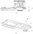
- FIG. 1 a schematic structural representation of an embodiment of a push button assembly according to the present application and 2 1 is a schematic structural detail view of the pushbutton holder according to FIG 1 indicates.
- the push button assembly 10 of the present application is used in an electronic device.
- the push button assembly 10 of the present embodiment includes a push button circuit board 100, which is adapted to be fixedly arranged on a housing front of the electronic device, a push button body 102, which is arranged on a side of the push button circuit board 100 facing away from the housing front, and a Pushbutton holder 104, which is arranged on a side of the pushbutton circuit board 100 facing away from the pushbutton body 102 and comprises a perimeter frame 1042 and a first fastening portion 1040 and a second fastening portion 1044 which are located on the perimeter frame 1042.
- the first attachment portion 1040 extends from the perimeter frame 1042 toward a side facing the push button circuit board 100
- the second attachment portion 1044 extends from the perimeter frame 1042 outward.
- the extending direction of the second attachment portion 1044 is perpendicular to the direction of extension of the first attachment section 1040.
- the first attachment section 1040 and the second attachment section 1044 are designed to be inserted into a latching slot on the housing front of the electronic device, so that the pushbutton holder 104 is releasably connected to the housing front of the electronic device.
- the delimiting frame 1042 serves to delimit the pushbutton body 102 on a side of the pushbutton circuit board 100 facing away from the housing front.
- the pushbutton circuit board 100 can be arranged firmly on the housing front of the electronic device by snapping it on or, alternatively, can also be formed in one piece on the housing front of the electronic device.
- the push button body 102 is arranged on the opposite side of the push button circuit board 100 from the housing front, and the push button holder 104 is arranged on the side of the push button body 102 opposite to the push button circuit board 100 .
- the push button holder 104 comprises a first fastening section 1040, a second fastening section 1044 and a perimeter frame 1042, so that the first fastening section 1040 and the second fastening section 1044 detachably connect to the housing front of the electronic device.
- the push button body 102 When connecting the push button holder 104 firmly to the front panel of the electronic device, the push button body 102 can be fixed to the side of the push button circuit board 100 facing away from the front panel by means of the limiting frame 1042, which ensures easy assembly of the push button body 102 to the electronic device. Since the pushbutton holder 104 is detachably connected to the front housing of the electronic device via the first fastening section 1040 and the second fastening section 1044, the pushbutton body 102 can be replaced after removing the pushbutton holder 104 from the front housing, which facilitates assembly and maintenance of the electronic device.
- the first attachment portion 1040 is located at a first edge of the bounding box 1042 and the second attachment portion 1044 is provided in a plurality, wherein the plurality of second attachment portions 1044 are each at a second edge, a third edge, and a fourth edge that is the first edge of the bounding box 1042 are arranged adjacent and opposite.
- the first fastening section 1040 and the second fastening section 1044 can each be a snap-in connection element and that a snap-in slot is provided on the housing front of the electronic device, which interacts with the first fastening section 1040 and the second fastening section 1044 of the pushbutton holder 104.
- first fastening section 1040 and the second fastening section 1044 are inserted directly into the latching slot, with which the fastening between the pushbutton holder 104 and the housing front of the electronic device is achieved.
- first fastening section 1040 and the second fastening section 1044 are pulled out of the locking slot, with which the pushbutton holder 104 can be removed from the housing front of the electronic device can be removed. This facilitates assembly and replacement of the push button body 102, and hence assembly and maintenance of the electronic device.
- a through hole 10400 is provided on the first fastening section 1040, the arrangement direction of which is perpendicular to the direction in which the first fastening section 1040 extends, with the first fastening section 1040 being inserted in the latching slot on the housing front of the electronic device having a through hole 10400 with a mounting hole on a housing of the electronic device connected is.
- a pin, screw or other fastener can be passed through the mounting hole on the electronic device housing and inserted into the through hole 10400 on the first mounting portion 1040 by matching the through hole 10400 with a mounting hole on the electronic device housing Device is connected when the first attachment portion 1040 is inserted into the locking slot on the front panel of the electronic device.
- the pushbutton body 102 includes a pushbutton disc 1020 and the perimeter frame 1042 is for receiving the pushbutton disc 1020 and for securing the pushbutton disc 1020 within the perimeter frame 1042 .
- the push button disk 1020 includes a plurality of silicone rubber push buttons
- the perimeter frame 1042 is provided with a plurality of receiving recesses uniquely associated with the plurality of silicone rubber push buttons.
- the receiving recess serves to receive the silicone rubber push button and ensures that the silicone rubber push button is protrudingly exposed on a side of the push button holder 104 facing away from the push button body 102 . It is understood that among the plural silicone rubber push buttons, such as number keys, power buttons, and restart buttons, a corresponding function is realized by each of the silicone rubber push buttons and by a combination of some of the silicone rubber push buttons.
- the push button body 102 includes a snap disk 1022 which is located on a side of the push button disk 1020 facing the push button circuit board 100 and rests against the push button circuit board 100 .
- a snap disk 1022 is provided between the push button circuit board 100 and the push button disk 1020 to serve as an electrically conductive point.
- the push button disk 1020 is pressed, a corresponding point of the snap disk 1022 is caused to sink, thereby contacting an electric circuit on the push button circuit board 100, thus establishing a circuit so that electric current flows and the whole electronic device can operate normally.
- the pushbutton disc 1020 could be formed by a plurality of separate silicone rubber pushbuttons mounted on an integral mounting substrate.
- the snap disk 1022 can also consist of several separate metal spring plates which are arranged and glued together in the same way.
- a double-sided adhesive tape (not shown) is provided, which is arranged along the edge of the push button circuit board 100 so that the point at which the snap disk 1022 on the push button Printed circuit board 100 is present, sealed.
- the seal between the snap-action disc 1022 and the pushbutton circuit board 100 can be ensured by the double-sided adhesive tape that the penetration of Moisture from the environment in which the push button assembly 10 is located is prevented from entering the push button assembly 10 and electrical circuit failure due to contact of the push button circuit board 100 with moisture is prevented.
- a sound transmission hole 1000 is provided on each of the pushbutton circuit board 100, the snap-action disc 1022, the pushbutton disc 1020 and the pushbutton holder 104 and is connected to one another. It is understood that the size and location of the sound passage hole 1000 on the push button circuit board 100 should be determined in consideration of the arrangement of the electric circuit on the push button circuit board 100, while the size and location of the sound passage hole 1000 on the snap disk 1022, of the push button disc 1020 and the push button holder 104 should be determined in accordance with both the size and location of the sound transmission hole 1000 on the push button circuit board 100 and the sound transmission effect of the push button assembly 10. Furthermore, the shape of the sound transmission hole 1000 can be determined according to actual needs and, for example, a round hole, a rectangular hole or even an elongated hole or a trapezoidal hole as in FIG 1 represented, conceivable.
- the location where the snap disk 1022 abuts the pushbutton circuit board 100 can be sealed by providing double-sided adhesive tape circumferentially around the edge of the pushbutton circuit board 100 .
- a double-sided adhesive tape can also be provided circumferentially at the edge of each sound transmission hole 1000 on the pushbutton circuit board 100, so that when the snap disk 1022 rests on the pushbutton circuit board 100, the double-sided adhesive tape on the edge of the sound transmission hole 1000 on the pushbutton circuit board 100 also the sealing effect between the snap disk 1022 and the pushbutton circuit board 100 and the ingress of moisture from the environment in which the pushbutton assembly 10 is located via the interconnected sound transmission holes 1000 on the pushbutton holder 104, the pushbutton disk 1020, the snap disk 1022 and the Push button circuit board 100 into push button assembly 10 prevented.
- the push button assembly 10 can achieve a waterproof rating of IP68, which is the highest waterproof rating for connectors.
- the push button assembly 10 may further include a speaker grille 106 disposed between the push button disc 1020 and the push button holder 104 for preventing contaminants from entering the interior of the push button assembly 10 via the sound passage hole 1000 . It is understood that impurities in a minute amount could enter the push button assembly 10 via the sound transmission hole 1000 on the push button holder 104 and the push button disk 1020, and by shielding via the speaker grille 106, the penetration of dust or other contaminants into the interior of the push button assembly 10 is largely prevented and thus interfering with the normal operation of the push button assembly 10 is avoided.
- a cutout 1002 is provided which allows the first fastening section 1040 and the second Fastening section 1044 is used to insert them into the locking slot on the front of the electronic device.
- the pushbutton circuit board 100, the snap-action disk 1022 and the pushbutton disk 1020 are also present between the pushbutton holder 104 and the housing front of the electronic device, by providing the recess 1002 at the corresponding location with the first fastening section 1040 and the second fastening section 1044 on the pushbutton circuit board 100, the snap-action disc 1022 and the pushbutton disc 1020, the pushbutton circuit board 100, the snap-action disc 1022 and the pushbutton disc 1020 prevent the first fastening section 1040 and the second fastening section 1044 from being inserted into the latching slot on the housing front of the electronic device are prevented, whereby assembly and disassembly of the push button holder 104 are facilitated.
- the present application further includes an electronic device. It will be on Figures 3 and 4 pointed out where 3 a schematic structural representation of an embodiment of the electronic device according to the present application and 4 a schematic structural detail view of the device body according to 3 indicates.
- the electronic device of the present embodiment includes a push button assembly 10 according to the above embodiment.
- For the push button assembly 10 of the electronic device reference is made to the content of the above embodiment.
- the electronic device includes a device body 20, which includes a housing 200, a speaker assembly 202 provided within the housing 200, and a housing front 204 located on the surface of the housing 200.
- the housing front 204 is located on one side of a sound emission surface of the speaker assembly 202.
- the push button assembly 10 is on one of
- Loudspeaker assembly 202 facing away from the front panel 204 arranged.
- the pushbutton holder in the pushbutton assembly 10 is releasably connected to the housing front 204 and when the pushbutton holder is firmly connected to the housing front 204, the pushbutton body in the pushbutton assembly 10 can be fixedly attached to the side of the pushbutton circuit board remote from the housing front 204 by means of the bounding box be, which provides for easy assembly of the push button body to the device body 20.
- the pushbutton body can be replaced after the pushbutton holder has been removed from the housing front 204, which facilitates assembly and maintenance of the electronic device as well as low installation and maintenance costs.
- a mounting hole 2000 is provided on the housing 200 of the electronic device, and a plug pin, a screw or another fastening element that can be passed through the mounting hole 2000 on the housing 200 of the electronic device and inserted into the through hole on the first fastening section. Since when the first fixing portion is inserted into the locking slot 2040 on the housing front 204 of the electronic device, the through hole on the first fixing portion is connected to a mounting hole 2000 on the housing 200 . Thus, the stable mounting of the push button holder to the electronic device can be ensured.
- the electronic device may be a walkie-talkie, a center console of a vehicle, and other devices with a push button device.
- the push button circuit board is first attached to the housing front 204 of the device body 20 . Then, a double-sided adhesive tape is provided circumferentially along the edge of the pushbutton circuit board, and the snap disk is adhered to the pushbutton circuit board via the double-sided adhesive tape. Then the push button disk is mounted on the snap disk. Finally, the first attachment portion and the second attachment portion of the push button holder are used to attach the push button holder and the front panel 204, and the perimeter frame of the push button holder is used to attach the push button disk between the snap disk and the push button holder, completing the assembly of the whole electronic device.
- the pushbutton assembly and electronic device disclosed may be implemented in other ways.
- the above embodiments of the push button assembly and the electronic device are only described schematically.
- the individual functional parts are subdivided only according to their logical functions. In a practical implementation, the subdivision can be done in other ways. For example let several functional parts can be combined with each other or integrated into several modules. Alternatively, individual functional parts may be physically separate.
Landscapes
- Push-Button Switches (AREA)
- Switch Cases, Indication, And Locking (AREA)
- Telephone Set Structure (AREA)
- Input From Keyboards Or The Like (AREA)
- Casings For Electric Apparatus (AREA)
Priority Applications (1)
| Application Number | Priority Date | Filing Date | Title |
|---|---|---|---|
| EP23184604.9A EP4250326B1 (fr) | 2019-06-28 | 2019-06-28 | Ensemble bouton et dispositif électronique |
Applications Claiming Priority (1)
| Application Number | Priority Date | Filing Date | Title |
|---|---|---|---|
| PCT/CN2019/093842 WO2020258288A1 (fr) | 2019-06-28 | 2019-06-28 | Ensemble bouton et dispositif électronique |
Related Child Applications (1)
| Application Number | Title | Priority Date | Filing Date |
|---|---|---|---|
| EP23184604.9A Division EP4250326B1 (fr) | 2019-06-28 | 2019-06-28 | Ensemble bouton et dispositif électronique |
Publications (4)
| Publication Number | Publication Date |
|---|---|
| EP3993003A1 true EP3993003A1 (fr) | 2022-05-04 |
| EP3993003A4 EP3993003A4 (fr) | 2022-06-22 |
| EP3993003B1 EP3993003B1 (fr) | 2023-07-12 |
| EP3993003C0 EP3993003C0 (fr) | 2023-07-12 |
Family
ID=74061477
Family Applications (2)
| Application Number | Title | Priority Date | Filing Date |
|---|---|---|---|
| EP23184604.9A Active EP4250326B1 (fr) | 2019-06-28 | 2019-06-28 | Ensemble bouton et dispositif électronique |
| EP19934819.4A Active EP3993003B1 (fr) | 2019-06-28 | 2019-06-28 | Ensemble bouton et dispositif électronique |
Family Applications Before (1)
| Application Number | Title | Priority Date | Filing Date |
|---|---|---|---|
| EP23184604.9A Active EP4250326B1 (fr) | 2019-06-28 | 2019-06-28 | Ensemble bouton et dispositif électronique |
Country Status (3)
| Country | Link |
|---|---|
| EP (2) | EP4250326B1 (fr) |
| CN (2) | CN114026667A (fr) |
| WO (1) | WO2020258288A1 (fr) |
Family Cites Families (17)
| Publication number | Priority date | Publication date | Assignee | Title |
|---|---|---|---|---|
| TW431683U (en) * | 1998-10-30 | 2001-04-21 | Hon Hai Prec Ind Co Ltd | Electrical connector |
| WO2005093770A1 (fr) * | 2004-03-25 | 2005-10-06 | Shin-Etsu Polymer Co., Ltd. | Organe de couverture pour commutateur à bouton-poussoir et méthode pour fabriquer celui-ci |
| CN101587790B (zh) * | 2008-05-21 | 2012-11-21 | 深圳富泰宏精密工业有限公司 | 键盘结构 |
| CN102118927A (zh) * | 2009-12-30 | 2011-07-06 | 深圳富泰宏精密工业有限公司 | 便携式电子装置壳体装配结构 |
| CN201655613U (zh) * | 2010-02-08 | 2010-11-24 | 金凌实业(杭州)有限公司 | 用于3d装置的按键机构 |
| CN201601055U (zh) * | 2010-03-15 | 2010-10-06 | 青岛海信电器股份有限公司 | 机械按键装置及采用该按键装置的电视机 |
| CN101908429B (zh) * | 2010-08-17 | 2013-08-28 | 青岛海信移动通信技术股份有限公司 | 按键固定结构以及便携式移动终端 |
| CN202196678U (zh) * | 2011-08-15 | 2012-04-18 | 惠州Tcl移动通信有限公司 | 一种扩大按键界面幅度的手机装置 |
| CN103094000B (zh) * | 2011-10-27 | 2014-11-19 | 希姆通信息技术(上海)有限公司 | 带钢片支架的按键卡扣 |
| CN102762061B (zh) * | 2012-06-29 | 2016-08-17 | 惠州Tcl移动通信有限公司 | 按键固定结构以及便携式移动终端 |
| CN104992863B (zh) * | 2015-06-26 | 2017-12-26 | 珠海格力电器股份有限公司 | 按键结构和遥控器 |
| CN105225872B (zh) * | 2015-09-25 | 2017-11-10 | 维沃移动通信有限公司 | 一种按键结构及电子设备 |
| CN105893958B (zh) * | 2016-03-31 | 2020-07-24 | 联想(北京)有限公司 | 一种按键装置及电子设备 |
| CN207149459U (zh) * | 2017-09-12 | 2018-03-27 | 西安Tcl软件开发有限公司 | 具有硅胶按键的电子设备 |
| CN208521220U (zh) * | 2018-08-10 | 2019-02-19 | 深圳市销邦科技股份有限公司 | 一种手持式移动智能终端设备 |
| CN109192576B (zh) * | 2018-08-22 | 2020-07-17 | Oppo广东移动通信有限公司 | 一种按键结构及终端设备 |
| CN210223842U (zh) * | 2019-06-28 | 2020-03-31 | 海能达通信股份有限公司 | 一种按键组件和电子设备 |
-
2019
- 2019-06-28 EP EP23184604.9A patent/EP4250326B1/fr active Active
- 2019-06-28 EP EP19934819.4A patent/EP3993003B1/fr active Active
- 2019-06-28 CN CN201980097993.XA patent/CN114026667A/zh active Pending
- 2019-06-28 CN CN202410483104.6A patent/CN118366810A/zh active Pending
- 2019-06-28 WO PCT/CN2019/093842 patent/WO2020258288A1/fr not_active Ceased
Also Published As
| Publication number | Publication date |
|---|---|
| EP3993003A4 (fr) | 2022-06-22 |
| EP3993003B1 (fr) | 2023-07-12 |
| CN114026667A (zh) | 2022-02-08 |
| EP4250326B1 (fr) | 2025-01-22 |
| EP4250326A2 (fr) | 2023-09-27 |
| CN118366810A (zh) | 2024-07-19 |
| WO2020258288A1 (fr) | 2020-12-30 |
| EP4250326C0 (fr) | 2025-01-22 |
| EP3993003C0 (fr) | 2023-07-12 |
| EP4250326A3 (fr) | 2023-10-11 |
Similar Documents
| Publication | Publication Date | Title |
|---|---|---|
| EP1192845B1 (fr) | Ventilateur a filtre pouvant etre monte dans un evidement de paroi | |
| EP1732375A2 (fr) | Ventilateur d'appareil | |
| DE69532905T2 (de) | Tragbares Funkgerät | |
| DE2941951A1 (de) | Hoergeraet mit einer leiterplatte als traeger fuer leitungsbahnen sowie elektrische und mechanische bauelemente und baustufen | |
| DE2603606A1 (de) | Elektrische subminiatur-anschlussanordnung | |
| DE102016122084A1 (de) | Elektronische Schaltungseinheit | |
| DE2632729B2 (de) | Elektronische Uhr | |
| DE10004752A1 (de) | Instrumentengruppe und Sicherungsblock | |
| EP2151151A1 (fr) | Codage, notamment pour un ensemble enfichable d'un tableau de distribution électrique | |
| DE202019005791U1 (de) | Drucktastenbaugruppe und elektronisches Gerät | |
| EP3993003B1 (fr) | Ensemble bouton et dispositif électronique | |
| DE202018100278U1 (de) | Bedien-/Anzeigemodul für eine Spülmaschine | |
| DE10227562A1 (de) | Abdeckrahmen für ein elektrisches Installationsgerät | |
| BE1030623B1 (de) | Vorrichtung und Verfahren für Gehäuse elektrischer Geräte | |
| DE112023001631T5 (de) | Vorrichtung zum schalten | |
| EP2453541B1 (fr) | Agencement de commutateurs électriques | |
| EP0521329A1 (fr) | Appareil pour sourds adapté pour être supporté entièrement par l'oreille et méthode de production | |
| DE102007045866B3 (de) | Montageanordnung und deren Verwendung in einem Installationsgerät | |
| EP0557742A1 (fr) | Ensemble d'interrupteurs à membrane | |
| DE3024702A1 (de) | Elektrische quarzuhr | |
| EP1575347B1 (fr) | Plaque ressort dans un boîtier faisant fonction d'écran pour un appareil électronique haute fréquence | |
| EP0054240A2 (fr) | Appareil électrique adapté à l'utilisation en plein air, notamment poste téléphonique pour installation de conversation en alternat, en duplex ou à haut-parleur | |
| DE202014002530U1 (de) | Im Gehörgang zu tragendes Hörgerät | |
| DE102005010271A1 (de) | Federblech in einem Gehäuse als Abschirmung für ein elektronisches hochfrequenztechnisches Gerät | |
| DE3445679A1 (de) | Gehaeuse zur aufnahme einer steuerplatine fuer muenzbetaetigte spielgeraete |
Legal Events
| Date | Code | Title | Description |
|---|---|---|---|
| STAA | Information on the status of an ep patent application or granted ep patent |
Free format text: STATUS: THE INTERNATIONAL PUBLICATION HAS BEEN MADE |
|
| PUAI | Public reference made under article 153(3) epc to a published international application that has entered the european phase |
Free format text: ORIGINAL CODE: 0009012 |
|
| STAA | Information on the status of an ep patent application or granted ep patent |
Free format text: STATUS: REQUEST FOR EXAMINATION WAS MADE |
|
| 17P | Request for examination filed |
Effective date: 20220125 |
|
| AK | Designated contracting states |
Kind code of ref document: A1 Designated state(s): AL AT BE BG CH CY CZ DE DK EE ES FI FR GB GR HR HU IE IS IT LI LT LU LV MC MK MT NL NO PL PT RO RS SE SI SK SM TR |
|
| REG | Reference to a national code |
Ref country code: DE Ref legal event code: R079 Free format text: PREVIOUS MAIN CLASS: H01H0013040000 Ref country code: DE Ref legal event code: R079 Ref document number: 502019008555 Country of ref document: DE Free format text: PREVIOUS MAIN CLASS: H01H0013040000 Ipc: H01H0013860000 |
|
| A4 | Supplementary search report drawn up and despatched |
Effective date: 20220525 |
|
| RIC1 | Information provided on ipc code assigned before grant |
Ipc: H01H 13/86 20060101AFI20220519BHEP |
|
| DAV | Request for validation of the european patent (deleted) | ||
| DAX | Request for extension of the european patent (deleted) | ||
| GRAP | Despatch of communication of intention to grant a patent |
Free format text: ORIGINAL CODE: EPIDOSNIGR1 |
|
| STAA | Information on the status of an ep patent application or granted ep patent |
Free format text: STATUS: GRANT OF PATENT IS INTENDED |
|
| INTG | Intention to grant announced |
Effective date: 20230124 |
|
| GRAS | Grant fee paid |
Free format text: ORIGINAL CODE: EPIDOSNIGR3 |
|
| GRAA | (expected) grant |
Free format text: ORIGINAL CODE: 0009210 |
|
| STAA | Information on the status of an ep patent application or granted ep patent |
Free format text: STATUS: THE PATENT HAS BEEN GRANTED |
|
| AK | Designated contracting states |
Kind code of ref document: B1 Designated state(s): AL AT BE BG CH CY CZ DE DK EE ES FI FR GB GR HR HU IE IS IT LI LT LU LV MC MK MT NL NO PL PT RO RS SE SI SK SM TR |
|
| REG | Reference to a national code |
Ref country code: CH Ref legal event code: EP |
|
| REG | Reference to a national code |
Ref country code: DE Ref legal event code: R096 Ref document number: 502019008555 Country of ref document: DE |
|
| REG | Reference to a national code |
Ref country code: IE Ref legal event code: FG4D Free format text: LANGUAGE OF EP DOCUMENT: GERMAN |
|
| U01 | Request for unitary effect filed |
Effective date: 20230713 |
|
| U07 | Unitary effect registered |
Designated state(s): AT BE BG DE DK EE FI FR IT LT LU LV MT NL PT SE SI Effective date: 20230725 |
|
| REG | Reference to a national code |
Ref country code: LT Ref legal event code: MG9D |
|
| PG25 | Lapsed in a contracting state [announced via postgrant information from national office to epo] |
Ref country code: GR Free format text: LAPSE BECAUSE OF FAILURE TO SUBMIT A TRANSLATION OF THE DESCRIPTION OR TO PAY THE FEE WITHIN THE PRESCRIBED TIME-LIMIT Effective date: 20231013 |
|
| PG25 | Lapsed in a contracting state [announced via postgrant information from national office to epo] |
Ref country code: ES Free format text: LAPSE BECAUSE OF FAILURE TO SUBMIT A TRANSLATION OF THE DESCRIPTION OR TO PAY THE FEE WITHIN THE PRESCRIBED TIME-LIMIT Effective date: 20230712 |
|
| PG25 | Lapsed in a contracting state [announced via postgrant information from national office to epo] |
Ref country code: IS Free format text: LAPSE BECAUSE OF FAILURE TO SUBMIT A TRANSLATION OF THE DESCRIPTION OR TO PAY THE FEE WITHIN THE PRESCRIBED TIME-LIMIT Effective date: 20231112 |
|
| PG25 | Lapsed in a contracting state [announced via postgrant information from national office to epo] |
Ref country code: RS Free format text: LAPSE BECAUSE OF FAILURE TO SUBMIT A TRANSLATION OF THE DESCRIPTION OR TO PAY THE FEE WITHIN THE PRESCRIBED TIME-LIMIT Effective date: 20230712 Ref country code: NO Free format text: LAPSE BECAUSE OF FAILURE TO SUBMIT A TRANSLATION OF THE DESCRIPTION OR TO PAY THE FEE WITHIN THE PRESCRIBED TIME-LIMIT Effective date: 20231012 Ref country code: IS Free format text: LAPSE BECAUSE OF FAILURE TO SUBMIT A TRANSLATION OF THE DESCRIPTION OR TO PAY THE FEE WITHIN THE PRESCRIBED TIME-LIMIT Effective date: 20231112 Ref country code: HR Free format text: LAPSE BECAUSE OF FAILURE TO SUBMIT A TRANSLATION OF THE DESCRIPTION OR TO PAY THE FEE WITHIN THE PRESCRIBED TIME-LIMIT Effective date: 20230712 Ref country code: GR Free format text: LAPSE BECAUSE OF FAILURE TO SUBMIT A TRANSLATION OF THE DESCRIPTION OR TO PAY THE FEE WITHIN THE PRESCRIBED TIME-LIMIT Effective date: 20231013 Ref country code: ES Free format text: LAPSE BECAUSE OF FAILURE TO SUBMIT A TRANSLATION OF THE DESCRIPTION OR TO PAY THE FEE WITHIN THE PRESCRIBED TIME-LIMIT Effective date: 20230712 |
|
| PG25 | Lapsed in a contracting state [announced via postgrant information from national office to epo] |
Ref country code: PL Free format text: LAPSE BECAUSE OF FAILURE TO SUBMIT A TRANSLATION OF THE DESCRIPTION OR TO PAY THE FEE WITHIN THE PRESCRIBED TIME-LIMIT Effective date: 20230712 |
|
| REG | Reference to a national code |
Ref country code: DE Ref legal event code: R097 Ref document number: 502019008555 Country of ref document: DE |
|
| PG25 | Lapsed in a contracting state [announced via postgrant information from national office to epo] |
Ref country code: SM Free format text: LAPSE BECAUSE OF FAILURE TO SUBMIT A TRANSLATION OF THE DESCRIPTION OR TO PAY THE FEE WITHIN THE PRESCRIBED TIME-LIMIT Effective date: 20230712 Ref country code: RO Free format text: LAPSE BECAUSE OF FAILURE TO SUBMIT A TRANSLATION OF THE DESCRIPTION OR TO PAY THE FEE WITHIN THE PRESCRIBED TIME-LIMIT Effective date: 20230712 Ref country code: CZ Free format text: LAPSE BECAUSE OF FAILURE TO SUBMIT A TRANSLATION OF THE DESCRIPTION OR TO PAY THE FEE WITHIN THE PRESCRIBED TIME-LIMIT Effective date: 20230712 Ref country code: SK Free format text: LAPSE BECAUSE OF FAILURE TO SUBMIT A TRANSLATION OF THE DESCRIPTION OR TO PAY THE FEE WITHIN THE PRESCRIBED TIME-LIMIT Effective date: 20230712 |
|
| PLBE | No opposition filed within time limit |
Free format text: ORIGINAL CODE: 0009261 |
|
| STAA | Information on the status of an ep patent application or granted ep patent |
Free format text: STATUS: NO OPPOSITION FILED WITHIN TIME LIMIT |
|
| 26N | No opposition filed |
Effective date: 20240415 |
|
| U20 | Renewal fee for the european patent with unitary effect paid |
Year of fee payment: 6 Effective date: 20240527 |
|
| PG25 | Lapsed in a contracting state [announced via postgrant information from national office to epo] |
Ref country code: MC Free format text: LAPSE BECAUSE OF FAILURE TO SUBMIT A TRANSLATION OF THE DESCRIPTION OR TO PAY THE FEE WITHIN THE PRESCRIBED TIME-LIMIT Effective date: 20230712 |
|
| REG | Reference to a national code |
Ref country code: CH Ref legal event code: PL |
|
| PG25 | Lapsed in a contracting state [announced via postgrant information from national office to epo] |
Ref country code: IE Free format text: LAPSE BECAUSE OF NON-PAYMENT OF DUE FEES Effective date: 20240628 |
|
| PG25 | Lapsed in a contracting state [announced via postgrant information from national office to epo] |
Ref country code: CH Free format text: LAPSE BECAUSE OF NON-PAYMENT OF DUE FEES Effective date: 20240630 |
|
| U20 | Renewal fee for the european patent with unitary effect paid |
Year of fee payment: 7 Effective date: 20250528 |
|
| PGFP | Annual fee paid to national office [announced via postgrant information from national office to epo] |
Ref country code: GB Payment date: 20250625 Year of fee payment: 7 |
|
| PG25 | Lapsed in a contracting state [announced via postgrant information from national office to epo] |
Ref country code: CY Free format text: LAPSE BECAUSE OF FAILURE TO SUBMIT A TRANSLATION OF THE DESCRIPTION OR TO PAY THE FEE WITHIN THE PRESCRIBED TIME-LIMIT; INVALID AB INITIO Effective date: 20190628 |
|
| PG25 | Lapsed in a contracting state [announced via postgrant information from national office to epo] |
Ref country code: HU Free format text: LAPSE BECAUSE OF FAILURE TO SUBMIT A TRANSLATION OF THE DESCRIPTION OR TO PAY THE FEE WITHIN THE PRESCRIBED TIME-LIMIT; INVALID AB INITIO Effective date: 20190628 |