EP3992985B1 - System und verfahren zur verarbeitung von patientendaten während diagnose und therapie - Google Patents
System und verfahren zur verarbeitung von patientendaten während diagnose und therapie Download PDFInfo
- Publication number
- EP3992985B1 EP3992985B1 EP21209044.3A EP21209044A EP3992985B1 EP 3992985 B1 EP3992985 B1 EP 3992985B1 EP 21209044 A EP21209044 A EP 21209044A EP 3992985 B1 EP3992985 B1 EP 3992985B1
- Authority
- EP
- European Patent Office
- Prior art keywords
- therapy
- diagnostic
- patient
- data
- provider
- Prior art date
- Legal status (The legal status is an assumption and is not a legal conclusion. Google has not performed a legal analysis and makes no representation as to the accuracy of the status listed.)
- Active
Links
- 238000002560 therapeutic procedure Methods 0.000 title claims description 272
- 238000000034 method Methods 0.000 title claims description 48
- 238000012545 processing Methods 0.000 title claims description 9
- 238000003745 diagnosis Methods 0.000 title description 20
- 230000015654 memory Effects 0.000 claims description 41
- 238000004891 communication Methods 0.000 claims description 36
- 238000012546 transfer Methods 0.000 claims description 19
- 230000029058 respiratory gaseous exchange Effects 0.000 claims description 18
- 208000019116 sleep disease Diseases 0.000 claims description 13
- 208000020685 sleep-wake disease Diseases 0.000 claims description 12
- 238000004458 analytical method Methods 0.000 claims description 9
- 230000004044 response Effects 0.000 claims description 4
- 238000005516 engineering process Methods 0.000 description 72
- 239000003570 air Substances 0.000 description 52
- 238000012360 testing method Methods 0.000 description 25
- 239000007789 gas Substances 0.000 description 18
- 230000000241 respiratory effect Effects 0.000 description 18
- 238000007726 management method Methods 0.000 description 15
- XLYOFNOQVPJJNP-UHFFFAOYSA-N water Substances O XLYOFNOQVPJJNP-UHFFFAOYSA-N 0.000 description 15
- 238000007789 sealing Methods 0.000 description 10
- 238000012384 transportation and delivery Methods 0.000 description 9
- 210000000214 mouth Anatomy 0.000 description 8
- 229910052760 oxygen Inorganic materials 0.000 description 8
- 238000002644 respiratory therapy Methods 0.000 description 8
- QVGXLLKOCUKJST-UHFFFAOYSA-N atomic oxygen Chemical compound [O] QVGXLLKOCUKJST-UHFFFAOYSA-N 0.000 description 7
- 230000006870 function Effects 0.000 description 7
- 239000001301 oxygen Substances 0.000 description 7
- 208000023504 respiratory system disease Diseases 0.000 description 7
- 238000011144 upstream manufacturing Methods 0.000 description 7
- 239000012530 fluid Substances 0.000 description 6
- 230000036541 health Effects 0.000 description 6
- 210000001331 nose Anatomy 0.000 description 6
- 208000001797 obstructive sleep apnea Diseases 0.000 description 6
- 230000008569 process Effects 0.000 description 6
- 238000004422 calculation algorithm Methods 0.000 description 5
- 208000037265 diseases, disorders, signs and symptoms Diseases 0.000 description 5
- 208000035475 disorder Diseases 0.000 description 5
- 230000003019 stabilising effect Effects 0.000 description 5
- 230000005540 biological transmission Effects 0.000 description 4
- 238000011513 continuous positive airway pressure therapy Methods 0.000 description 4
- 238000013523 data management Methods 0.000 description 4
- 238000002405 diagnostic procedure Methods 0.000 description 4
- 238000010438 heat treatment Methods 0.000 description 4
- 210000004072 lung Anatomy 0.000 description 4
- 210000002345 respiratory system Anatomy 0.000 description 4
- 230000000153 supplemental effect Effects 0.000 description 4
- 210000003437 trachea Anatomy 0.000 description 4
- 238000011282 treatment Methods 0.000 description 4
- 238000009423 ventilation Methods 0.000 description 4
- 239000011358 absorbing material Substances 0.000 description 3
- 239000000853 adhesive Substances 0.000 description 3
- 230000001070 adhesive effect Effects 0.000 description 3
- 210000000621 bronchi Anatomy 0.000 description 3
- 238000013461 design Methods 0.000 description 3
- 238000010586 diagram Methods 0.000 description 3
- 230000000694 effects Effects 0.000 description 3
- 239000000463 material Substances 0.000 description 3
- 238000012544 monitoring process Methods 0.000 description 3
- 208000018360 neuromuscular disease Diseases 0.000 description 3
- 238000012552 review Methods 0.000 description 3
- 208000024891 symptom Diseases 0.000 description 3
- 238000012795 verification Methods 0.000 description 3
- CURLTUGMZLYLDI-UHFFFAOYSA-N Carbon dioxide Chemical compound O=C=O CURLTUGMZLYLDI-UHFFFAOYSA-N 0.000 description 2
- 206010008501 Cheyne-Stokes respiration Diseases 0.000 description 2
- 208000006545 Chronic Obstructive Pulmonary Disease Diseases 0.000 description 2
- 230000009471 action Effects 0.000 description 2
- 210000003484 anatomy Anatomy 0.000 description 2
- 230000008901 benefit Effects 0.000 description 2
- 210000000988 bone and bone Anatomy 0.000 description 2
- 210000003123 bronchiole Anatomy 0.000 description 2
- 210000000845 cartilage Anatomy 0.000 description 2
- 238000003759 clinical diagnosis Methods 0.000 description 2
- 238000004590 computer program Methods 0.000 description 2
- 238000013500 data storage Methods 0.000 description 2
- 230000001419 dependent effect Effects 0.000 description 2
- 238000001035 drying Methods 0.000 description 2
- 229920001971 elastomer Polymers 0.000 description 2
- 210000003128 head Anatomy 0.000 description 2
- 210000000867 larynx Anatomy 0.000 description 2
- 238000004377 microelectronic Methods 0.000 description 2
- 210000003928 nasal cavity Anatomy 0.000 description 2
- 230000003287 optical effect Effects 0.000 description 2
- 238000013515 script Methods 0.000 description 2
- 230000001225 therapeutic effect Effects 0.000 description 2
- 230000000007 visual effect Effects 0.000 description 2
- 210000001260 vocal cord Anatomy 0.000 description 2
- ORILYTVJVMAKLC-UHFFFAOYSA-N Adamantane Natural products C1C(C2)CC3CC1CC2C3 ORILYTVJVMAKLC-UHFFFAOYSA-N 0.000 description 1
- NOQGZXFMHARMLW-UHFFFAOYSA-N Daminozide Chemical compound CN(C)NC(=O)CCC(O)=O NOQGZXFMHARMLW-UHFFFAOYSA-N 0.000 description 1
- 230000005355 Hall effect Effects 0.000 description 1
- 206010021079 Hypopnoea Diseases 0.000 description 1
- 208000008589 Obesity Diseases 0.000 description 1
- 208000004756 Respiratory Insufficiency Diseases 0.000 description 1
- 238000011374 additional therapy Methods 0.000 description 1
- 239000000443 aerosol Substances 0.000 description 1
- 239000012080 ambient air Substances 0.000 description 1
- 229940124326 anaesthetic agent Drugs 0.000 description 1
- 230000003444 anaesthetic effect Effects 0.000 description 1
- 230000000844 anti-bacterial effect Effects 0.000 description 1
- 208000008784 apnea Diseases 0.000 description 1
- 239000008280 blood Substances 0.000 description 1
- 210000004369 blood Anatomy 0.000 description 1
- 238000004364 calculation method Methods 0.000 description 1
- 229910002092 carbon dioxide Inorganic materials 0.000 description 1
- 239000001569 carbon dioxide Substances 0.000 description 1
- 230000008859 change Effects 0.000 description 1
- 230000000295 complement effect Effects 0.000 description 1
- 238000007599 discharging Methods 0.000 description 1
- 238000006073 displacement reaction Methods 0.000 description 1
- 239000000806 elastomer Substances 0.000 description 1
- 210000002409 epiglottis Anatomy 0.000 description 1
- 238000001704 evaporation Methods 0.000 description 1
- 230000008020 evaporation Effects 0.000 description 1
- 230000001815 facial effect Effects 0.000 description 1
- 210000001061 forehead Anatomy 0.000 description 1
- 210000001983 hard palate Anatomy 0.000 description 1
- 201000000615 hard palate cancer Diseases 0.000 description 1
- 208000000122 hyperventilation Diseases 0.000 description 1
- 238000003780 insertion Methods 0.000 description 1
- 230000037431 insertion Effects 0.000 description 1
- 230000003434 inspiratory effect Effects 0.000 description 1
- 230000003993 interaction Effects 0.000 description 1
- 210000001847 jaw Anatomy 0.000 description 1
- 239000004973 liquid crystal related substance Substances 0.000 description 1
- 210000004373 mandible Anatomy 0.000 description 1
- 238000004519 manufacturing process Methods 0.000 description 1
- 238000012986 modification Methods 0.000 description 1
- 230000004048 modification Effects 0.000 description 1
- 210000000537 nasal bone Anatomy 0.000 description 1
- 210000002184 nasal cartilage Anatomy 0.000 description 1
- 210000002850 nasal mucosa Anatomy 0.000 description 1
- 235000020824 obesity Nutrition 0.000 description 1
- 239000013307 optical fiber Substances 0.000 description 1
- 230000008520 organization Effects 0.000 description 1
- 210000003300 oropharynx Anatomy 0.000 description 1
- 238000002496 oximetry Methods 0.000 description 1
- 238000001441 oximetry spectrum Methods 0.000 description 1
- 239000002245 particle Substances 0.000 description 1
- 229920001296 polysiloxane Polymers 0.000 description 1
- 238000007781 pre-processing Methods 0.000 description 1
- 239000012858 resilient material Substances 0.000 description 1
- 201000004193 respiratory failure Diseases 0.000 description 1
- 230000036412 respiratory physiology Effects 0.000 description 1
- 230000000284 resting effect Effects 0.000 description 1
- 230000035945 sensitivity Effects 0.000 description 1
- 210000003625 skull Anatomy 0.000 description 1
- 201000002859 sleep apnea Diseases 0.000 description 1
- 238000010321 sleep therapy Methods 0.000 description 1
- 210000001584 soft palate Anatomy 0.000 description 1
- 210000004872 soft tissue Anatomy 0.000 description 1
- 230000005236 sound signal Effects 0.000 description 1
- 230000003068 static effect Effects 0.000 description 1
- 230000009182 swimming Effects 0.000 description 1
- 238000010998 test method Methods 0.000 description 1
- 210000000779 thoracic wall Anatomy 0.000 description 1
- 210000002105 tongue Anatomy 0.000 description 1
Images


Classifications
-
- G—PHYSICS
- G16—INFORMATION AND COMMUNICATION TECHNOLOGY [ICT] SPECIALLY ADAPTED FOR SPECIFIC APPLICATION FIELDS
- G16H—HEALTHCARE INFORMATICS, i.e. INFORMATION AND COMMUNICATION TECHNOLOGY [ICT] SPECIALLY ADAPTED FOR THE HANDLING OR PROCESSING OF MEDICAL OR HEALTHCARE DATA
- G16H10/00—ICT specially adapted for the handling or processing of patient-related medical or healthcare data
- G16H10/60—ICT specially adapted for the handling or processing of patient-related medical or healthcare data for patient-specific data, e.g. for electronic patient records
-
- A—HUMAN NECESSITIES
- A61—MEDICAL OR VETERINARY SCIENCE; HYGIENE
- A61B—DIAGNOSIS; SURGERY; IDENTIFICATION
- A61B5/00—Measuring for diagnostic purposes; Identification of persons
- A61B5/08—Detecting, measuring or recording devices for evaluating the respiratory organs
- A61B5/0826—Detecting or evaluating apnoea events
-
- A—HUMAN NECESSITIES
- A61—MEDICAL OR VETERINARY SCIENCE; HYGIENE
- A61M—DEVICES FOR INTRODUCING MEDIA INTO, OR ONTO, THE BODY; DEVICES FOR TRANSDUCING BODY MEDIA OR FOR TAKING MEDIA FROM THE BODY; DEVICES FOR PRODUCING OR ENDING SLEEP OR STUPOR
- A61M16/00—Devices for influencing the respiratory system of patients by gas treatment, e.g. mouth-to-mouth respiration; Tracheal tubes
- A61M16/0057—Pumps therefor
-
- A—HUMAN NECESSITIES
- A61—MEDICAL OR VETERINARY SCIENCE; HYGIENE
- A61M—DEVICES FOR INTRODUCING MEDIA INTO, OR ONTO, THE BODY; DEVICES FOR TRANSDUCING BODY MEDIA OR FOR TAKING MEDIA FROM THE BODY; DEVICES FOR PRODUCING OR ENDING SLEEP OR STUPOR
- A61M16/00—Devices for influencing the respiratory system of patients by gas treatment, e.g. mouth-to-mouth respiration; Tracheal tubes
- A61M16/06—Respiratory or anaesthetic masks
- A61M16/0605—Means for improving the adaptation of the mask to the patient
- A61M16/0616—Means for improving the adaptation of the mask to the patient with face sealing means comprising a flap or membrane projecting inwards, such that sealing increases with increasing inhalation gas pressure
- A61M16/0622—Means for improving the adaptation of the mask to the patient with face sealing means comprising a flap or membrane projecting inwards, such that sealing increases with increasing inhalation gas pressure having an underlying cushion
-
- A—HUMAN NECESSITIES
- A61—MEDICAL OR VETERINARY SCIENCE; HYGIENE
- A61M—DEVICES FOR INTRODUCING MEDIA INTO, OR ONTO, THE BODY; DEVICES FOR TRANSDUCING BODY MEDIA OR FOR TAKING MEDIA FROM THE BODY; DEVICES FOR PRODUCING OR ENDING SLEEP OR STUPOR
- A61M16/00—Devices for influencing the respiratory system of patients by gas treatment, e.g. mouth-to-mouth respiration; Tracheal tubes
- A61M16/06—Respiratory or anaesthetic masks
- A61M16/0666—Nasal cannulas or tubing
-
- A—HUMAN NECESSITIES
- A61—MEDICAL OR VETERINARY SCIENCE; HYGIENE
- A61M—DEVICES FOR INTRODUCING MEDIA INTO, OR ONTO, THE BODY; DEVICES FOR TRANSDUCING BODY MEDIA OR FOR TAKING MEDIA FROM THE BODY; DEVICES FOR PRODUCING OR ENDING SLEEP OR STUPOR
- A61M16/00—Devices for influencing the respiratory system of patients by gas treatment, e.g. mouth-to-mouth respiration; Tracheal tubes
- A61M16/10—Preparation of respiratory gases or vapours
- A61M16/14—Preparation of respiratory gases or vapours by mixing different fluids, one of them being in a liquid phase
- A61M16/16—Devices to humidify the respiration air
-
- G—PHYSICS
- G16—INFORMATION AND COMMUNICATION TECHNOLOGY [ICT] SPECIALLY ADAPTED FOR SPECIFIC APPLICATION FIELDS
- G16H—HEALTHCARE INFORMATICS, i.e. INFORMATION AND COMMUNICATION TECHNOLOGY [ICT] SPECIALLY ADAPTED FOR THE HANDLING OR PROCESSING OF MEDICAL OR HEALTHCARE DATA
- G16H20/00—ICT specially adapted for therapies or health-improving plans, e.g. for handling prescriptions, for steering therapy or for monitoring patient compliance
- G16H20/40—ICT specially adapted for therapies or health-improving plans, e.g. for handling prescriptions, for steering therapy or for monitoring patient compliance relating to mechanical, radiation or invasive therapies, e.g. surgery, laser therapy, dialysis or acupuncture
-
- G—PHYSICS
- G16—INFORMATION AND COMMUNICATION TECHNOLOGY [ICT] SPECIALLY ADAPTED FOR SPECIFIC APPLICATION FIELDS
- G16H—HEALTHCARE INFORMATICS, i.e. INFORMATION AND COMMUNICATION TECHNOLOGY [ICT] SPECIALLY ADAPTED FOR THE HANDLING OR PROCESSING OF MEDICAL OR HEALTHCARE DATA
- G16H40/00—ICT specially adapted for the management or administration of healthcare resources or facilities; ICT specially adapted for the management or operation of medical equipment or devices
- G16H40/40—ICT specially adapted for the management or administration of healthcare resources or facilities; ICT specially adapted for the management or operation of medical equipment or devices for the management of medical equipment or devices, e.g. scheduling maintenance or upgrades
-
- G—PHYSICS
- G16—INFORMATION AND COMMUNICATION TECHNOLOGY [ICT] SPECIALLY ADAPTED FOR SPECIFIC APPLICATION FIELDS
- G16H—HEALTHCARE INFORMATICS, i.e. INFORMATION AND COMMUNICATION TECHNOLOGY [ICT] SPECIALLY ADAPTED FOR THE HANDLING OR PROCESSING OF MEDICAL OR HEALTHCARE DATA
- G16H40/00—ICT specially adapted for the management or administration of healthcare resources or facilities; ICT specially adapted for the management or operation of medical equipment or devices
- G16H40/60—ICT specially adapted for the management or administration of healthcare resources or facilities; ICT specially adapted for the management or operation of medical equipment or devices for the operation of medical equipment or devices
- G16H40/67—ICT specially adapted for the management or administration of healthcare resources or facilities; ICT specially adapted for the management or operation of medical equipment or devices for the operation of medical equipment or devices for remote operation
-
- Y—GENERAL TAGGING OF NEW TECHNOLOGICAL DEVELOPMENTS; GENERAL TAGGING OF CROSS-SECTIONAL TECHNOLOGIES SPANNING OVER SEVERAL SECTIONS OF THE IPC; TECHNICAL SUBJECTS COVERED BY FORMER USPC CROSS-REFERENCE ART COLLECTIONS [XRACs] AND DIGESTS
- Y02—TECHNOLOGIES OR APPLICATIONS FOR MITIGATION OR ADAPTATION AGAINST CLIMATE CHANGE
- Y02A—TECHNOLOGIES FOR ADAPTATION TO CLIMATE CHANGE
- Y02A90/00—Technologies having an indirect contribution to adaptation to climate change
- Y02A90/10—Information and communication technologies [ICT] supporting adaptation to climate change, e.g. for weather forecasting or climate simulation
Definitions
- the present technology relates to the diagnosis and treatment of respiratory-related disorders.
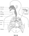
- the respiratory system of the body facilitates gas exchange.
- the nose and mouth form the entrance to the airways of a patient.
- the airways include a series of branching tubes, which become narrower, shorter and more numerous as they penetrate deeper into the lung.
- the prime function of the lung is gas exchange, allowing oxygen to move from the air into the venous blood and carbon dioxide to move out.
- the trachea divides into right and left main bronchi, which further divide eventually into terminal bronchioles.
- the bronchi make up the conducting airways, and do not take part in gas exchange. Further divisions of the airways lead to the respiratory bronchioles, and eventually to the alveoli.
- the alveolated region of the lung is where the gas exchange takes place, and is referred to as the respiratory zone. See " Respiratory Physiology", by John B. West, Lippincott Williams & Wilkins, 9th edition published 2011 .
- Some examples of respiratory disorders include: Obstructive Sleep Apnea (OSA), Cheyne Stokes Respiration (CSR), Obesity Hyperventilation Syndrome (OHS), Chronic Obstructive Pulmonary Disease (COPD), Neuromuscular Disease (NMD) or chest wall disorders.
- OSA Obstructive Sleep Apnea
- CSR Cheyne Stokes Respiration
- OOS Obesity Hyperventilation Syndrome
- COS Chronic Obstructive Pulmonary Disease
- NMD Neuromuscular Disease
- chest wall disorders include: Obstructive Sleep Apnea (OSA), Cheyne Stokes Respiration (CSR), Obesity Hyperventilation Syndrome (OHS), Chronic Obstructive Pulmonary Disease (COPD), Neuromuscular Disease (NMD) or chest wall disorders.
- COPD Chronic Obstructive Pulmonary Disease
- NMD Neuromuscular Disease
- Patients' interaction with the health system generally comprises two main stages or phases - a diagnostic stage and a treatment (also referred to as "therapy") stage.
- the diagnostic providers can be qualified medical practitioners, also referred to as physicians or doctors, or assisting practitioners referred to as clinicians.
- a diagnostic providers Instead of conducting a sleep test in a sleep lap or sleep clinic, a diagnostic providers increasingly use portable take home testing devices to diagnose patients with sleep disorder breathing. Once the patient is diagnosed, they may be put on a suitable therapy.
- the application of the respiratory therapy defines the therapy stage, during which the patient is treated for the purpose of managing the patient's condition and/or ameliorating its symptoms.
- the services to supply the CPAP devices used for such therapy and monitor the progress of the patient's therapy may be provided by a therapy provider organisation, such as a Home Medical Equipment (HME) company.
- a therapy provider from the therapy provider company, such as a therapy clinician may configure the device as per directions from the prescription, and put the patient on a program to monitor their ongoing adherence to therapy and the patient's therapy progress.
- patients suffering from sleep apnea may be diagnosed via a Home Sleep Test by a diagnostic provider and prescribed a therapy device, such as a continuous positive airway pressure ("CPAP") device, for home respiratory therapy that is prescribed to operate at a particular pressure.
- a therapy device such as a continuous positive airway pressure ("CPAP") device
- the therapy provider for this patient will provide the device and set the required pressure and other settings.
- the therapy device may be configured for automatic initial setup, based on the prescription settings in the diagnostic prescription issued by the diagnostic provider.
- the therapy provider may be responsible for setting the patient for therapy. This may involve selection of a treatment mask, humidifier, conduits and other accessories, which may or may not be specified in the prescription issued by the diagnostic provider. Apart from the initial setup, the therapy provider will also monitor the therapy data from the patient therapy sessions. If the patient's therapy progress is unsatisfactory or there are other problems with the therapy, the therapy provider may refer the patient back to the diagnostic provider for review and modification to the therapy.
- Insurance companies, or other assessing or reimbursing entity computer 103 often require evidence that the patient has been diagnosed in an appropriate manner before paying for the diagnosis.
- a diagnostic provider will need to present the appropriate data from a Home Sleep Test device (which will also be referred to in this specification as a diagnostic device) and a diagnosis needs to be made available that is signed by a qualified physician.
- insurance companies often want to track whether a patient once diagnosed with a medical condition successfully proceeds to and remains on the therapy for which they are prescribed. This process can be inefficient and time consuming, with very poor patient traceability during the transfer of the patient between the diagnostic and therapy provider.
- the transfer may be inconvenient and disruptive, because multiple records of the patient (e.g. one during the diagnostic stage patient management and another one during the therapy stage) are being created on different software packages and in different software environments.
- the communication between the two stages also currently involves paper records and/or faxed documents. This may cause inconvenience to the patients and the diagnostic and therapy service providers, as well as cause errors in the patient's records.
- a therapy system may comprise a Respiratory Pressure Therapy Device (RPT device), an air circuit, a humidifier, a patient interface, and data management.
- RPT device Respiratory Pressure Therapy Device
- a patient interface may be used to interface respiratory equipment to its user, for example by providing a flow of breathable gas.
- the flow of breathable gas may be provided via a mask to the nose and/or mouth, a tube to the mouth or a tracheostomy tube to the trachea of the user.
- the patient interface may form a seal, e.g. with a face region of the patient, to facilitate the delivery of gas at a pressure at sufficient variance with ambient pressure to effect therapy, e.g. a positive pressure of about 10cmH2O.
- the patient interface may not include a seal sufficient to facilitate delivery to the airways of a supply of gas at a positive pressure of about 10cmH2O.
- the design of a patient interface presents a number of challenges.
- the face has a complex three-dimensional shape.
- the size and shape of noses varies considerably between individuals. Since the head includes bone, cartilage and soft tissue, different regions of the face respond differently to mechanical forces.
- the jaw or mandible may move relative to other bones of the skull. The whole head may move during the course of a period of respiratory therapy.
- masks designed solely for aviators, mask designed as part of personal protection equipment (e.g. filter masks), SCUBA masks or for the administration of anaesthetics may be tolerable for their original application, but nevertheless be undesirably uncomfortable to be worn for extended periods of time, e.g. several hours. This is even more so if the mask is to be worn during sleep.
- Nasal CPAP therapy is highly effective to treat certain respiratory disorders, provided patients comply with therapy. If a mask is uncomfortable, or difficult to use a patient may not comply with therapy. Since it is often recommended that a patient regularly wash their mask, if a mask is difficult to clean (e.g. difficult to assemble or disassemble), patients may not clean their mask and this may impact on patient compliance.
- a mask for other applications may not be suitable for use in treating sleep disordered breathing
- a mask designed for use in treating sleep disordered breathing may be suitable for other applications.
- masks for delivery of nasal CPAP during sleep form a distinct field.
- Patient interfaces may include a seal-forming portion. Since it is in direct contact with the patient's face, the shape and configuration of the seal-forming portion can have a direct impact the effectiveness and comfort of the patient interface.
- a patient interface may be partly characterised according to the design intent of where the seal-forming portion is to engage with the face in use.
- a seal-forming portion may comprise two sub-portions to engage with respective left and right nares.
- a seal-forming portion may comprise a single element that surrounds both nares in use. Such single element may be designed to for example overlay an upper lip region and a nasal bridge region of a face.
- a seal-forming portion may comprise an element that surrounds a mouth region in use, e.g. by forming a seal on a lower lip region of a face.
- a seal-forming portion may comprise a single element that surrounds both nares and a mouth region in use.
- These different types of patient interfaces may be known by a variety of names by their manufacturer including nasal masks, full-face masks, nasal pillows, nasal puffs and oro-nasal masks.
- a seal-forming portion that may be effective in one region of a patient's face may be in appropriate in another region, e.g. because of the different shape, structure, variability and sensitivity regions of the patient's face. For example, a seal on swimming goggles that overlays a patient's forehead may not be appropriate to use on a patient's nose.
- Certain seal-forming portions may be designed for mass manufacture such that one design fit and be comfortable and effective for a wide range of different face shapes and sizes. To the extent to which there is a mismatch between the shape of the patient's face, and the seal-forming portion of the mass-manufactured patient interface, one or both must adapt in order for a seal to form.
- seal-forming portion extends around the periphery of the patient interface, and is intended to seal against the user's face when force is applied to the patient interface with the seal-forming portion in confronting engagement with the user's face.
- the seal-forming portion may include an air or fluid filled cushion, or a moulded or formed surface of a resilient seal element made of an elastomer such as a rubber.
- seal-forming portion incorporates a flap seal of thin material so positioned about the periphery of the mask so as to provide a self-sealing action against the face of the user when positive pressure is applied within the mask.
- flap seal of thin material so positioned about the periphery of the mask so as to provide a self-sealing action against the face of the user when positive pressure is applied within the mask.
- additional force may be required to effect a seal, or the mask may leak.
- shape of the seal-forming portion does not match that of the patient, it may crease or buckle in use, giving rise to leaks.
- seal-forming portion may comprise a friction-fit element, e.g. for insertion into a naris.
- seal-forming portion may use adhesive to effect a seal. Some patients may find it inconvenient to constantly apply and remove an adhesive to their face.
- nasal pillow is found in the Adam Circuit manufactured by Puritan Bennett.
- Another nasal pillow, or nasal puff is the subject of US Patent 4,782,832 (Trimble et al.), assigned to Puritan-Bennett Corporation .
- ResMed Limited has manufactured the following products that incorporate nasal pillows: SWIFT nasal pillows mask, SWIFT II nasal pillows mask.
- a seal-forming portion of a patient interface used for positive air pressure therapy is subject to the corresponding force of the air pressure to disrupt a seal.
- a variety of techniques have been used to position the seal-forming portion, and to maintain it in sealing relation with the appropriate portion of the face.
- Another technique is the use of one or more straps and stabilising harnesses. Many such harnesses suffer from being one or more of ill-fitting, bulky, uncomfortable and awkward to use.
- RPT device used for treating sleep disordered breathing is the S9 Sleep Therapy System, manufactured by ResMed.
- S9 Sleep Therapy System manufactured by ResMed.
- Another example of an RPT device is a ventilator.
- Ventilators such as the ResMed Stellar TM Series of Adult and Paediatric Ventilators may provide support for invasive and non-invasive non-dependent ventilation for a range of patients for treating a number of conditions such as but not limited to NMD, OHS and COPD.
- RPT devices have also been known as flow generators.
- the ResMed Elo TM 150 ventilator and ResMed VS III TM ventilator may provide support for invasive and non-invasive dependent ventilation suitable for adult or paediatric patients for treating a number of conditions. These ventilators provide volumetric and barometric ventilation modes with a single or double limb circuit.
- RPT devices typically comprise a pressure generator, such as a motor-driven blower or a compressed gas reservoir, and are configured to supply a flow of air to the airway of a patient. In some cases, the flow of air may be supplied to the airway of the patient at positive pressure.
- the outlet of the RPT device is connected via an air circuit to a patient interface such as those described above.
- RPT devices typically also include an inlet filter, various sensors and a microprocessor-based controller.
- a blower may include a servo-controlled motor, a volute and an impeller.
- a brake for the motor may be implemented to more rapidly reduce the speed of the blower so as to overcome the inertia of the motor and impeller. The braking can permit the blower to more rapidly achieve a lower pressure condition in time for synchronization with expiration despite the inertia.
- the pressure generator may also include a valve capable of discharging generated air to atmosphere as a means for altering the pressure delivered to the patient as an alternative to motor speed control.
- the sensors measure, amongst other things, motor speed, mass flow rate and outlet pressure, such as with a pressure transducer or the like.
- the controller may include data storage capacity with or without integrated data retrieval and display functions.
- Medical humidifiers are used to increase humidity and/or temperature of the flow of breathable gas in relation to ambient air when required, typically where the patient may be asleep or resting (e.g. at a hospital).
- a medical humidifier is preferably small for bedside placement, and it is preferably configured to only humidify and/or heat the flow of breathable gas delivered to the patient without humidifying and/or heating the patient's surroundings.
- Room-based systems e.g. a sauna, an air conditioner, an evaporative cooler
- a humidifier with a flow generator or RPT device and the patient interface produces humidified gas that minimizes drying of the nasal mucosa and increases patient airway comfort.
- warm air applied generally to the face area in and about the patient interface is more comfortable than cold air.
- Respiratory humidifiers are available in many forms and may be a standalone device that is coupled to a respiratory apparatus via an air circuit, is integrated with or configured to be coupled to the relevant respiratory apparatus. While known passive humidifiers can provide some relief, generally a heated humidifier may be used to provide sufficient humidity and temperature to the air so that the patient will be comfortable.
- Humidifiers typically comprise a water reservoir or tub having a capacity of several hundred milliliters (ml), a heating element for heating the water in the reservoir, a control to enable the level of humidification to be varied, a gas inlet to receive gas from the flow generator or RPT device, and a gas outlet adapted to be connected to an air circuit that delivers the humidified gas to the patient interface.
- Heated passover humidification is one common form of humidification used with a RPT device.
- the heating element may be incorporated in a heater plate which sits under, and is in thermal contact with, the water tub.
- heat is transferred from the heater plate to the water reservoir primarily by conduction.
- the air flow from the RPT device passes over the heated water in the water tub resulting in water vapour being taken up by the air flow.
- the ResMed H4i TM and H5i TM Humidifiers are examples of such heated passover humidifiers that are used in combination with ResMed S8 and S9 CPAP devices respectively.
- a bubble or diffuser humidifier In a bubble or diffuser humidifier the air is conducted below the surface of the water and allowed to bubble back to the top.
- a jet humidifier produces an aerosol of water and baffles or filters may be used so that the particles are either removed or evaporated before leaving the humidifier.
- a wicking humidifier uses a water absorbing material, such as sponge or paper, to absorb water by capillary action. The water absorbing material is placed within or adjacent at least a portion of the air flow path to allow evaporation of the water in the absorbing material to be taken up into the air flow.
- ResMed HumiCare TM D900 humidifier uses a CounterStream TM technology that directs the air flow over a large surface area in a first direction whilst supplying heated water to the large surface area in a second opposite direction.
- the ResMed HumiCare TM D900 humidifier may be used with a range of invasive and non-invasive ventilators.
- the present technology relates to the diagnosis and treatment of sleep disorder breathing patients and related respiratory insufficiencies.
- the diagnostic stage and the therapy stage of patient management are somewhat disconnected and incoherent. What is needed is an integrated electronic system which links the diagnostic provider and therapy provider to the same patient database, and allows for easy generation, management, and transfer of a patient's diagnostic information directly to the prescribed flow generator (which will also be referred to in herein as a therapy device).
- the present technology therefore relates to a method and system for an integrated processing and management of the patient data during the diagnostic and therapy stages.
- the described system provides diagnostic providers and therapy device providers with a simple and fast way to generate a clinical diagnosis from a diagnostic device and to transfer that patient's record and diagnostic data directly to the therapy provider responsible for the patient's ongoing care.
- US2008/114689A1 discloses a set of program instructions which is configured to facilitate communication of data between at least one patient device and the system.
- a communication for patient information management and a method of facilitating the secure transmission of data of a patient device over a network to a patient management system are also disclosed.
- WO2012/168848A1 discloses a respiratory therapy device that is configured, such that it switches from one therapy mode to another therapy mode. The mode parameters for the latter therapy mode are based on usage information gather during the former therapy mode.
- a server contains memory configured to store medical device data, and a processor in communication with the memory.
- the processor is configured to receive diagnostic and therapy data for a plurality of medical device users, and to process diagnostic report data and therapy device usage data.
- a successful download of data may be based on whether the received diagnostic data from the device contains a predetermined duration of recording information and conforms to acceptable clinical ranges.
- Therapy compliance may be based on whether the received medical device usage data satisfies predetermined usage criteria, such as a number of hours of continuous usage or another predetermined criterion.
- the processor is also configured to receive a request from the diagnostic provider or health providers for the diagnostic stage, as well as a compliance status for one or more of the patients using medical devices, and to transfer access to those patients from one provider to another.
- a medical device can either be a Diagnostic Home Sleep Testing Device or a Therapy Device (e.g. a Flow Generator) used for respiratory therapy.
- the memory of the server may be further configured to store device identifiers, e.g., a unique ID number, wherein the medical device data for each of the plurality of medical device users includes a device identifier, which may be a unique device identifier, and wherein the processor of the server is further configured to associate the medical device usage data with a medical device user based on the received device identifiers.
- the server's processor is further configured to regenerate medical device diagnostic data from at least one of the plurality of medical device users, based on a user determined change in analysis parameters.
- a clinical diagnostic summary report may be provided, the report being of a format that allows an assessing entity to accept the report as verification of diagnosis.
- the report may contain summary statistics from the diagnostic test data, a physician's interpretation of the test results and an electronic signature, as proof of review or acceptance.
- a prescription based on a clinical diagnostic report may be provided.
- the prescription may be of a format that allows a therapy provider to supply a device, configure it for therapy and begin monitoring a schedule for reimbursement.
- the prescription may contain a specified therapy device (e.g. CPAP), an itemised list of accessories (e.g. mask type), pressure settings for the device and an electronic signature.
- CPAP a specified therapy device
- itemised list of accessories e.g. mask type
- pressure settings for the device e.g. mask type
- an electronic signature e.g. mask type
- diagnostic and compliance indications are generated and displayed as selectable icons on the screen of a user.
- a compliance report may be provided.
- the report may be of a format that allows an assessing entity to accept the report as verification of compliance.
- the report may contain a numerical or graphical indication of compliance.
- a healthcare professional associated with a diagnostic provider may access a website and select on the website one or more medical device users (patients) for which diagnostic information is available. The user may then select a therapy provider from a list of eligible organizations within the system and send the selected patients' diagnostic information to the selected organization. A user within the therapy provider will then receive a notification of the availability of diagnostic information for each of the one or more transferred medical device users, as well as the prescription information required to set up the patients on therapy.
- a method for patient data processing during diagnosis and therapy of sleep disorder breathing may be performed.
- the method may include generating, by one or more computing devices, an electronic patient record for a patient; during a diagnostic stage of the patient, storing, by the one or more computing devices, diagnostic-related data in the electronic patient record; providing, by the one or more computing devices, a diagnostic medical practitioner with access to the electronic patient record; during a therapy stage of the patient, providing, by the one or more computing devices, a treating medical practitioner with access to the electronic patient record; and updating, by the one or more computing devices, the electronic patient record to include therapy-related data.
- the method may include storing at least one of reports and prescriptions, generated during either the diagnostic stage or the therapy stage, in the electronic patient record.
- the diagnostic stage is at an end, the treating medical practitioner is notified and provided access to at least one of diagnostic data and prescription data of the patient.
- Therapy settings from a therapy prescription may be retrieved from the electronic patient record and used to automatically configure a therapy device for the patient.
- the automatic configuration may be effected by way of a network connection or a memory card.
- the data storage, processing, and access during the diagnostic stage and the therapy stage are performed on a single software platform and on a single physical system of servers.
- the diagnostic stage may include receiving data from a diagnostic device and the therapy stage may include receiving data from a therapy medical device, the therapy medical device being a flow generator for respiratory therapy.
- a disclosed method may include receiving, by one or more computing devices, medical device data for a plurality of medical device users; storing, by the one or more computing devices, the medical device data; determining, by the one or more computing devices, whether to process the medical device data as diagnostic information or as compliance information, based on a predetermined criterion related to identification data of the medical devices; if the medical device data is processed as diagnostic data, generating, by the one or more computing devices, diagnostic information based on predetermined analysis criteria; enabling, by the one or more computing devices, an electronic transfer of at least one of an clinical diagnosis report to an associated therapy provider, wherein the diagnosis report is based on the diagnostic information; and transmitting, by the one or more computing devices, a therapy settings to a therapy device associated with the diagnosis report.
- receiving the medical device data further comprises receiving a signal that one of the medical devices has data available for uploading.
- the medical device may be a home sleep testing device or a flow generator used for respiratory therapy.
- a generated diagnostic report may contain statistical indications which assist diagnosis and provide an area where a healthcare professional may input their clinical interpretation.
- the diagnostic report may also include a prescription for therapy that identifies one or more therapy devices and one or more therapeutic settings to be used by a patient.
- the diagnostic report for therapy may be displayed as HTML on a web browser or as a Portable Document Format (PDF).
- PDF Portable Document Format
- the method may also include assigning a therapy provider to a patient that is ready for therapy; transferring diagnostic information for the patient to the assigned therapy provider; and electronically importing therapy settings from the diagnostic information onto the therapy device to be used by the patient.
- an apparatus for integrated electronic management of diagnostic and therapy data of a plurality of sleep disorder breathing patients may include: a memory configured to store medical data, and one or more processors in communication with the memory.
- the one or more processors may be configured to receive medical device data for a plurality of medical device users; associate the received medical device data with a corresponding patient records; determine whether received medical device data is diagnostic or usage data; update the patient records in accordance with the determination of whether the received medical device data is diagnostic or usage data; store a list of therapy providers within a system of therapy providers; receive a request to display the list from a diagnostic provider; receive diagnostic data from the plurality of medical devices; generate summary statistics by processing the diagnostic data using a set of predetermined analysis criteria; receive a request generated by a clinical user; and transmit, in response to the request, a diagnostic report comprising the summary statistics.
- the processors may also be configured to store a list of medical devices and accessory items; receive a request to display the list by a clinical user; receive clinical settings information generated by the clinical user; receive text generated by the clinical user; transmit a prescription for therapy report displaying a selected item manifest and clinical settings; securely allow access to diagnostic and prescription data of a patient record by the selected therapy provider; dynamically update the therapy provider's available patient list with at least one patient record; display the additional patient record in the patient list; securely display patient information, diagnostic reports and prescription for therapy reports as selected by a therapy provider user; receive a request to assign a patient with a therapy device ID that corresponds to the prescription; and automatically transfer clinical settings information into the memory from the prescription.
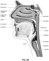
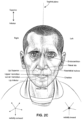
- Fig. 2C is a front view of a face with several features of surface anatomy identified including the lip superior, upper vermillion, lower vermillion, lip inferior, mouth width, endocanthion, a nasal ala, nasolabial sulcus and cheilion.
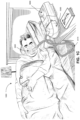
- Fig. 3a shows an example of a patient interface known in the prior art.
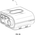
- Fig. 5A shows a humidifier in accordance with one aspect of the present technology.
- Fig. 6A shows a model typical breath waveform of a person while sleeping, the horizontal axis is time, and the vertical axis is respiratory flow. While the parameter values may vary, a typical breath may have the following approximate values: tidal volume, Vt, 0.5L, inhalation time, Ti, 1.6s, peak inspiratory flow, Qpeak, 0.4 L/s, exhalation time, Te, 2.4s, peak expiratory flow, Qpeak, -0.5 L/s.
- the total duration of the breath, Ttot is about 4s.
- the person typically breathes at a rate of about 15 breaths per minute (BPM), with Ventilation, Vent, about 7.5 L/s.
- BPM breaths per minute
- a typical duty cycle the ratio of Ti to Ttot is about 40%.
- the present system comprises an apparatus for treating a respiratory disorder.
- the apparatus may comprise a flow generator or blower for supplying pressurised respiratory gas, such as air, to the patient 1000 via an air delivery tube leading to a patient interface 3000.
- the present technology comprises a method for treating a respiratory disorder comprising the step of applying positive pressure to the entrance of the airways of a patient 1000.
- the present technology comprises a method of treating Obstructive Sleep Apnea in a patient by applying nasal continuous positive airway pressure to the patient
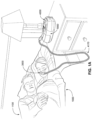
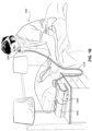
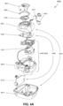
- a non-invasive patient interface 3000 in accordance with one aspect of the present technology comprises the following functional aspects: a seal-forming structure 3100, a plenum chamber 3200, a positioning and stabilising structure 3300, a vent 3400 and a connection port 3600 for connection to air circuit 4170.
- a functional aspect may be provided by one or more physical components.
- one physical component may provide one or more functional aspects.
- the seal-forming structure 3100 is arranged to surround an entrance to the airways of the patient so as to facilitate the supply of air at positive pressure to the airways.
- a seal-forming structure 3100 provides a sealing-forming surface, and may additionally provide a cushioning function.
- a seal-forming structure 3100 in accordance with the present technology may be constructed from a soft, flexible, resilient material such as silicone.
- the seal-forming structure 3100 comprises a sealing flange and a support flange.
- the sealing flange comprises a relatively thin member with a thickness of less than about 1mm, for example about 0.25mm to about 0.45mm, that extends around the perimeter 3210 of the plenum chamber 3200.
- Support flange may be relatively thicker than the sealing flange.
- the support flange is disposed between the sealing flange and the marginal edge of the plenum chamber 3200, and extends at least part of the way around the perimeter 3210.
- the support flange is or includes a spring-like element and functions to support the sealing flange from buckling in use. In use the sealing flange can readily respond to system pressure in the plenum chamber 3200 acting on its underside to urge it into tight sealing engagement with the face.
- the seal-forming portion of the non-invasive patient interface 3000 comprises a pair of nasal puffs, or nasal pillows, each nasal puff or nasal pillow being constructed and arranged to form a seal with a respective naris of the nose of a patient.
- Nasal pillows in accordance with an aspect of the present technology include: a frusto-cone, at least a portion of which forms a seal on an underside of the patient's nose; a stalk, a flexible region on the underside of the cone and connecting the cone to the stalk.
- the structure to which the nasal pillow of the present technology is connected includes a flexible region adjacent the base of the stalk.
- the flexible regions can act in concert to facilitate a universal joint structure that is accommodating of relative movement- both displacement and angular- of the frusto-cone and the structure to which the nasal pillow is connected.
- the frusto-cone may be axially displaced towards the structure to which the stalk is connected.
- the non-invasive patient interface 3000 comprises a seal-forming portion that forms a seal in use on an upper lip region (that is, the lip superior) of the patient's face.
- the non-invasive patient interface 3000 comprises a seal-forming portion that forms a seal in use on a chin-region of the patient's face.
- the plenum chamber 3200 has a perimeter 321.0 that is shaped to be complementary to the surface contour of the face of an average person in the region where a seal will form in use. In use, a marginal edge of the plenum chamber 3200 is positioned in close proximity to an adjacent surface of the face. Actual contact with the face is provided by the seal-forming structure 3100. Preferably the seal-forming structure 3100 extends in use about the entire perimeter 3210 of the plenum chamber 3200.
- the plenum chamber 3200 may surround and/or be in fluid communication with the nares of the patient where the plenum chamber 3200 is a part of a nasal mask (e.g. shown in Fig 1b ). In another form, the plenum chamber 3200 may surround and/or be in fluid communication with the nares and the mouth of the patient where the plenum chamber 3200 is a part of a full-face mask (e.g., shown in Fig. 1C ). In yet another form, the plenum chamber 3200 may engage and/or be in fluid communication with one or more of the nares of the patient where the plenum chamber 3200 is a part of nasal pillows.
- the seal-forming structure 3100 of the patient interface 3000 of the present technology is held in sealing position in use by the positioning and stabilising structure 3300.
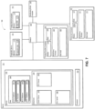
- An example RPT device 4000 that may be suitable for implementing aspects of the present technology may include mechanical and pneumatic components 4100, electrical components 4200 and may be programmed to execute one or more of the control methodologies or algorithms described throughout this specification.
- the RPT device may have an external housing 4010, preferably formed in two parts, an upper portion 4012 of the external housing 4010, and a lower portion 4014 of the external housing 4010.
- the external housing 4010 may include one or more panel(s) 4015.
- the RPT device 4000 comprises a chassis 4016 that supports one or more internal components of the RPT device 4000.
- a pneumatic block 4020 is supported by, or formed as part of the chassis 401.6.
- the RPT device 4000 may include a handle 4018.
- the pneumatic path of the RPT device 4000 preferably comprises an inlet air filter 4112, an inlet muffler 4122, a controllable pressure device 4140 capable of supplying air at positive pressure (preferably a blower 4142), and an outlet muffler 4124.
- One or more flow sensors 4272 and pressure sensors 4274 are included in the pneumatic path.
- the preferred pneumatic block 4020 comprises a portion of the pneumatic path that is located within the external housing 4010.
- the RPT device 4000 preferably has an electrical power supply 4210, one or more input devices 4220, a central controller 4230, a therapy device controller 4240 and/or any of the controllers previously described, a pressure device 4140, one or more protection circuits 4250, memory 4260, transducers (also referred to as sensors) 4270, data communication interface 4280 and one or more output devices 4290.
- Electrical components 4200 may be mounted on a single Printed Circuit Board Assembly (PCBA) 4202.
- PCBA Printed Circuit Board Assembly
- the RPT device 4000 may include more than one PCBA 4202.
- the central controller 4230 of the RPT device 4000 which may include one or more processors, can be programmed to execute one or more algorithm modules, preferably including a pre-processing module, a therapy engine module, a pressure control module, and further preferably a fault condition module. It may further include a vent control module that may be configured with one or more of the vent control methodologies described throughout this specification.
- a RPT device in accordance with one form of the present technology may include an air filter 4110, or a plurality of air filters 4110.
- an inlet air filter 4112 is located at the beginning of the pneumatic path upstream of a blower 4142. See Fig. 4B .
- an outlet air filter 4114 for example an antibacterial filter, is located between an outlet of the pneumatic block 4020 and a patient interface 3000. See Fig. 4B .
- an inlet muffler 4122 is located in the pneumatic path upstream of a blower 4142. See Fig. 4B .
- an outlet muffler 4124 is located in the pneumatic path between the blower 4142 and a patient interface 3000. See Fig. 4B .
- a pressure device 4140 for producing a flow of air at positive pressure is a controllable blower 4142.
- the blower may include a brushless DC motor 4144 with one or more impellers housed in a volute.
- the blower may be preferably capable of delivering a supply of air, for example about 120 litres/minute, at a positive pressure in a range from about 4 cmH 2 O to about 20 cmH 2 O, or in other forms up to about 30 cmH 2 O.
- the pressure device 4140 is under the control of the therapy device controller 4240.
- one or more transducers 4270 are located upstream of the pressure device 4140.
- the one or more transducers 4270 are constructed and arranged to measure properties of the air at that point in the pneumatic path.
- one or more transducers 4270 are located downstream of the pressure device 4140, and upstream of the air circuit 4170.
- the one or more transducers 4270 are constructed and arranged to measure properties of the air at that point in the pneumatic path.
- one or more transducers 4270 are located proximate to the patient interface 3000.
- an anti-spill back valve is located between the humidifier 5000 and the pneumatic block 4020.
- the anti-spill back valve is constructed and arranged to reduce the risk that water will flow upstream from the humidifier 5000, for example to the motor 4144.
- An air circuit 4170 in accordance with an aspect of the present technology is constructed and arranged to allow a flow of air or breathable gasses between the pneumatic block 4020 and the patient interface 3000.
- supplemental oxygen 4180 is delivered to a point in the pneumatic path.
- supplemental oxygen 4180 is delivered upstream of the pneumatic block 4020.
- supplemental oxygen 4180 is delivered to the air circuit 4170.
- supplemental oxygen 4180 is delivered to the patient interface 3000.
- power supply 4210 is internal of the external housing 4010 of the RPT device 4000. In another form of the present technology, power supply 4210 is external of the external housing 4010 of the RPT device 4000.
- power supply 4210 provides electrical power to the RPT device 4000 only. In another form of the present technology, power supply 4210 provides electrical power to both RPT device 4000 and humidifier 5000. The power supply may also optionally provide power to any actuator, controller and/or sensors for a vent arrangement as described throughout this specification
- a RPT device 4000 includes one or more input devices 4220 in the form of buttons, switches or dials to allow a person to interact with the device. These may be implemented for entering settings for operation of the components of the RPT device such as the vent arrangement.
- the buttons, switches or dials may be physical devices, or software devices accessible via a touch screen.
- the buttons, switches or dials may, in one form, be physically connected to the external housing 4010, or may, in another form, be in wireless communication with a receiver that is in electrical connection to the central controller 4230.
- the input device 4220 may be constructed and arranged to allow a person to select a value and/or a menu option.
- the central controller 4230 is a dedicated electronic circuit configured to receive input signal(s) from the input device 4220, and to provide output signal(s) to the output device 4290 and / or the therapy device controller 4240.
- the central controller 4230 is an application-specific integrated circuit. In another form, the central controller 4230 comprises discrete electronic components.
- the central controller 4230 is a processor suitable to control a RPT device 4000 such as an x86 INTEL processor.
- a processor of a central controller 4230 suitable to control a RPT device 4000 in accordance with another form of the present technology includes a processor based on ARM Cortex-M processor from ARM Holdings.
- ARM Cortex-M processor from ARM Holdings.
- an STM32 series microcontroller from ST MICROELECTRONICS may be used.
- Another processor suitable to control a RPT device 4000 in accordance with a further alternative form of the present technology includes a member selected from the family ARM9-based 32-bit RISC CPUs.
- a member selected from the family ARM9-based 32-bit RISC CPUs For example, an STR9 series microcontroller from ST MICROELECTRONICS may be used.
- a 16-bit RISC CPU may be used as the processor for the RPT device 4000.
- the processor is configured to receive input signal(s) from one or more transducers 4270, and one or more input devices 4220.
- the processor is configured to provide output signal(s) to one or more of an output device 4290.
- a therapy device controller 4240 a data communication interface 4280 and humidifier controller 5250.
- the processor of the central controller 4230 is configured to implement the one or more methodologies described herein such as the one or more algorithms 4300 expressed as computer programs stored in a non-transitory computer readable storage medium, such as memory 4260.
- processors(s) may be integrated with a RPT device 4000.
- the processor(s) may be implemented discretely from the flow generation components of the RPT device 4000, such as for purpose of performing any of the methodologies described herein without directly controlling delivery of a respiratory therapy.
- such a processor may perform any of the methodologies described herein for purposes of determining control settings for a ventilator or other respiratory related events by analysis of stored data such as from any of the sensors described herein.
- such a processor may perform any of the methodologies described herein for purposes controlling operation of any vent arrangement described in this specification.
- RPT device 4000 includes a clock 4232 that is connected to processor.
- therapy device controller 4240 is a pressure control module 4330 that forms part of the algorithms 4300 executed by the processor of the central controller 4230.
- therapy device controller 4240 is a dedicated motor control integrated circuit.
- a MC33035 brushless DC motor controller manufactured by ONSEMI is used.
- a RPT device 4000 in accordance with the present technology comprises one or more protection circuits 4250.
- protection circuit 4250 in accordance with the present technology is an electrical protection circuit.
- protection circuit 4250 in accordance with the present technology is a temperature or pressure safety circuit.
- the RPT device 4000 includes memory 4260, preferably non-volatile memory.
- memory 4260 may include battery powered static RAM.
- memory 4260 may include volatile RAM.
- memory 4260 is located on PCBA 4202.
- Memory 4260 may be in the form of EEPROM, or NAND flash.
- RPT device 4000 includes removable form of memory 4260, for example a memory card made in accordance with the Secure Digital (SD) standard.
- SD Secure Digital
- the memory 4260 acts as a non-transitory computer readable storage medium on which is stored computer program instructions expressing the one or more methodologies described herein, such as the one or more algorithms 4300.
- Transducers may be internal of the device, or external of the RPT device. External transducers may be located for example on or form part of the air delivery circuit, e.g. the patient interface. External transducers may be in the form of noncontact sensors such as a Doppler radar movement sensor that transmit or transfer data to the RPT device.
- a flow sensor 4272 in accordance with the present technology may be based on a differential pressure transducer, for example, an SDP600 Series differential pressure transducer from SENSIRION.
- the differential pressure transducer is in fluid communication with the pneumatic circuit, with one of each of the pressure transducers connected to respective first and second points in a flow restricting element.
- a signal representing total flow Qt from the flow sensor 4272 is received by the processor.
- a pressure transducer 4274 in accordance with the present technology is located in fluid communication with the pneumatic circuit.
- An example of a suitable pressure transducer is a sensor from the HONEYWELL ASDX series.
- An alternative suitable pressure transducer is a sensor from the NPA Series from GENERAL ELECTRIC.
- a signal from the pressure transducer 4274 is received by the central controller processor.
- the signal from the pressure transducer 4274 is filtered prior to being received by the central controller 4230.
- a motor speed signal is generated.
- a motor speed signal is preferably provided by therapy device controller 4240.
- Motor speed may, for example, be generated by a speed sensor 4276, such as a Hall effect sensor.
- a data communication interface 4280 is provided, and is connected to central controller processor.
- Data communication interface 4280 is preferably connectable to remote external communication network 4282.
- Data communication interface 4280 is preferably connectable to local external communication network 4284.
- remote external communication network 4282 is connectable to remote external device 4286.
- local external communication network 4284 is connectable to local external device 4288.
- data communication interface 4280 is part of processor of central controller 4230. In another form, data communication interface 4280 is an integrated circuit that is separate from the central controller processor.
- remote external communication network 4282 is the Internet.
- the data communication interface 4280 may use wired communication (e.g. via Ethernet, or optical fibre) or a wireless protocol to connect to the Internet.
- local external communication network 4284 utilises one or more communication standards, such as Bluetooth, or a consumer infrared protocol.
- remote external device 4286 is one or more computers, for example a cluster of networked computers.
- remote external device 4286 may be virtual computers, rather than physical computers. In either case, such remote external device 4286 may be accessible to an appropriately authorised person such as a clinician.
- local external device 4288 is a personal computer, mobile phone, tablet or remote control.
- An output device 4290 in accordance with the present technology may take the form of one or more of a visual, audio and haptic unit.
- a visual display may be a Liquid Crystal Display (LCD) or Light Emitting Diode (LED) display.
- a display driver 4292 receives as an input the characters, symbols, or images intended for display on the display 4294 and converts them to commands that cause the display 4294 to display those characters, symbols, or images.
- a display 4294 is configured to visually display characters, symbols, or images in response to commands received from the display driver 4292.
- the display 4294 may be an eight-segment display, in which case the display driver 4292 converts each character or symbol, such as the figure "0", to eight logical signals indicating whether the eight respective segments are to be activated to display a particular character or symbol.
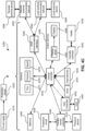
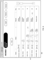
- Fig. 7 depicts an example system 100 in which aspects of the disclosure may be implemented. This example should not be considered as limiting the scope of the disclosure or usefulness of the features described herein.
- the system is compatible with, and processes data from, both diagnostic and therapy devices.
- patient medical diagnostic device 101 may be any sleep testing device used in connection with diagnosis of the patient's sleep-related breathing disorder.
- Therapy device 105 may be any device used in connection with providing therapy for the patient's sleep-related breathing disorder.
- the diagnostic device 101 and therapy device 105 may each include the RPT device 4000, humidifier 5000, and patient interface 3000 described herein.
- the system may be configured to not only associate the received medical device data with a corresponding patient record, but also determine whether the received medical device data is diagnostic usage data or therapy usage data and update the patient records accordingly, based on predetermined one or more criteria.
- the data identification may be associated with the data itself or with a device ID from which it is received. If the medical device data is determined as diagnostic data, the system may be configured to process the diagnostic data and to generate a diagnostic report and/or a prescription based on predetermined analysis criteria. The system may be further configured to display the diagnostic report and/or the prescription to a diagnostic provider for review and to enable an electronic transfer of a diagnosis report or a therapy prescription, based on the diagnostic data, to a therapy provider.
- System 100 has the ability to seamlessly transfer a patient's health information (including demographic and medical data) directly from diagnosis through to patient therapy within the same system within a single patient record. To facilitate this workflow, system 100 may have the following functional features:
- therapy provider to access the diagnostic data, as well as therapy settings information from the initial prescription data, as saved in the patient's record, or even for the therapy device to be automatically configured via a cable connection, wireless connection, or a memory card, by accessing this record.
- diagnostic data 111 may be recorded on a storage medium, also referred to as memory, 112.
- Diagnostic data 111 may include any data relating to the patient's sleep test, such as date, time and duration of test, as well as physiological data obtained during the test, such as recorded respiratory flow data, respiratory effort data, oximetry and pulse data, or other clinical information.
- Memory 112 may be of any non-transitory type capable of storing information accessible by a processor, including a computer-readable medium, or other medium that stores data that may be read with the aid of an electronic device, such as a hard-drive, memory card, ROM, RAM, DVD or other optical disks, as well as other write-capable and read-only memories.
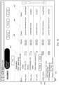
- Server 201 includes a processor 210 and a memory 220 for storing data 230 and instructions 234.
- Memory 220 stores information accessible by processor 210, including instructions 234 that may be executed or otherwise used by the processor 21.
- the memory 220 may be of any non-transitory type capable of storing information accessible by the processor, including a computer-readable medium, or other medium that stores data that may be read with the aid of an electronic device, such as a hard-drive, memory card, ROM, RAM, DVD or other optical disks, as well as other write-capable and read-only memories.
- Systems and methods may include different combinations of the foregoing, whereby different portions of the instructions and data are stored on different types of media.
- the instructions 234 may be any set of instructions to be executed directly (such as machine code) or indirectly (such as scripts) by the processor.
- the instructions may be stored as computer code on the computer-readable medium.
- the terms "instructions” and “programs” may be used interchangeably herein.
- the instructions may be stored in object code format for direct processing by the processor, or in any other computer language including scripts or collections of independent source code modules that are interpreted on demand or compiled in advance. Functions, methods and routines of the instructions are explained in more detail below.
- Instructions 234 may also contain instructions for operating one or more virtual servers, such as Communication (Comm) server 240, Easy Care Online (ECO) Server 250, and Communication Abstraction Layer (CAL) server 260.
- Communication Communication
- ECO Easy Care Online
- CAL Communication Abstraction Layer
- the Communications Server is responsible for communicating with wireless Therapy Devices and validating their output.
- the Communications Server's core responsibilities may include, communicating with Flow Generators via a Communication Module or inbuilt Communications Device; validating the incoming wireless data; and converting the wireless data into a format which can be read by the CAL server.
- the CAL server is responsible for communicating with Therapy Devices.
- the CAL server's core responsibilities may include, obtaining daily summary data for active patients; retrieving and changing therapy device settings; and converting raw therapy device data into an easily digestible format.
- the ECO Server is responsible for application functionality within the system.
- the ECO Server's core responsibilities includes, presenting patient and device information within the user interface, and writing and managing patient health information; and running application related processes.
- the data 230 may be retrieved, stored or modified by processor 210 in accordance with the instructions 234.
- the data may be stored in computer registers, in a relational database as a table having a plurality of different fields and records, XML documents or flat files.
- the data may also be formatted in any computer-readable format.
- the data may comprise any information useful in identifying the relevant information, such as numbers, descriptive text, proprietary codes, references to data stored in other areas of the same memory or different memories (including other locations accessible through other network connections) or information that is used by a function to calculate the relevant data.
- Data 230 may include one or more databases, including a Comm database 231, CAL database 232, ECO database 233, and HST database 235. Various types of data may be saved in these databases.
- the Comm. database 231, CAL database 232 and the ECO database 233 may store data associated with the respective servers, as described above.
- the HST database may store diagnostic data received from diagnostic devices 101.
- the processor 210 may be any conventional processor, including commercially available processors. Alternatively, the processor may be a dedicated device such as an ASIC or FPGA. Although Fig. 2 functionally illustrates the processor, memory, and other elements of server 201 as being within the same block, it will be understood by those of ordinary skill in the art that the processor and memory may actually comprise multiple processors and memories that may or may not be stored within the same physical housing. For example, memory may be a hard drive or other storage media located in a housing different from that of server 201. Accordingly, references to a processor or computer will be understood to include references to a collection of processors or computers or memories that may or may not operate in parallel or even be located at the same site.
- server 201 may be referred to as both a system and an apparatus.
- Computers 102, 103 and 104 may include all of the components normally used in connection with a computer, such as a central processing unit (CPU), memory (e.g., RAM and internal hard drives) for storing data 120 and 121 and instructions 130 and 131 (e.g. a web browser for displaying webpages in HTML and a portable document format (PDP) reader), an electronic display 110 and 115 (e.g., a monitor having a screen, a small LCD touch-screen or any other electrical device that is operable to display information), and user input 160 and 161 (e.g., a mouse, keyboard, touch screen, and/or microphone).
- CPU central processing unit
- memory e.g., RAM and internal hard drives
- data 120 and 121 and instructions 130 and 131 e.g. a web browser for displaying webpages in HTML and a portable document format (PDP) reader
- PDP portable document format
- an electronic display 110 and 115 e.g., a monitor having a screen, a small LCD touch
- the memory 112 may be internal to diagnostic device 101 which may be accessed by connecting an USB data cable to a separate computer.
- diagnostic device in such a case may be interpreted broadly to include a personal computer, such as a desktop or mobile computer, which contains usage data, including diagnostic data 111 collected from a medical device, such as a home sleep testing device.
- Fig. 2 illustrates server 201 and computers 101-104 as being connected via a network 150, each two or more devices within system 100 may be connected via a separate network or via the Internet.
- any one of the ECO server 250 and its associated ECO database 233, the Comm server 240 and its associated Comm database 231 and the CAL server 260 and its associated CAL database 232 may reside on a device at a location that is remote from the remaining servers.
- at least two of these servers, such as the Comm server 240, Comm database 231, CAL server 260. and CAL database 232, may exist on a single device.
- the diagnostic device 101 may collect any one of the following types of data Polysomnography (PSG) data, polygraphy data, oximetry data, pneumatic or Respiratory Inductance Plethysmography (RIP)-based respiratory effort data, respiratory flow data, audio signal data, body position data etc.
- PSG Polysomnography
- RIP Respiratory Inductance Plethysmography
- the patient's record is first created during the diagnostic stage, when the patient is approved for running a diagnostic test.
- the patient's record may comprise any data that is associated with the patient or with the patient's condition, such as the patient's personal details (name, gender, age, address, contact details etc.), symptoms, treating physician, insurance provider, type of insurance cover etc.
- diagnostic provider's computer 104 where the patient's record is created, it is transferred to the ECO database of server 201.
- computer 104 may not be a personal computer, but an administration computer used at the diagnostic provider clinic. As such, this computer may be operated, at least partially, not by the specific diagnostic physician responsible for the testing and diagnosis of the respective patient, but by a data administrator on the site. For example, it can be envisaged that such an administrator may be responsible for creating the patient's record.
- the diagnostic device collects diagnostic data indicating any respiratory condition that the patient may have, as well as other information, such as the type and model of the diagnostic device, the patient's details, including these of the referring diagnostic physician, time and dates of usage etc.
- the diagnostic device saves the diagnostic test data 111 in memory 112.
- a user of system 100 such as a user of diagnostic provider computer 104, may have a remote access to the memory 112 of the medical diagnostic device 101.
- user of diagnostic provider computer 104 may extract the portable memory card of device 101 and download the data to computer 104.
- a web browser 131 on the diagnostic provider computer 104 may then be used to contact server 201 and upload diagnostic data 111 to one or more of the databases 231, 232, 233 and 235.
- the diagnostic data 111 provided to server 201 from diagnostic device 101 may be stored in a CAL database 232, which may identify the type of patient device from which it came. For example, each diagnostic device 101 may be assigned a device ID, which is provided to server 201 along with the diagnostic data. The diagnostic data may then be stored by server 201 in a database that uses the device ID to associate the received data with the appropriate patient diagnostic device 101.
- the usage data from therapy device 105 may be processed in a similar manner.
- a patient is required to use a medical diagnostic device for a set duration and exhibit certain clinical symptoms in order to be eligible to qualify for therapy of the patient's sleep disorder breathing.
- a patient who has been ordered a home sleep test may be required to use the diagnostic device for at least four hours and exhibit an Apnea-Hypopnea Index (AHI) of greater than 5 in order for a physician to write a prescription for CPAP therapy.
- the prescription (also referred to as prescription data or prescription information) may be saved in the HST database 235).
- System 100 may be used to track whether the patient has been compliant in using the diagnostic device and may assist a physician in making a diagnosis.
- a diagnosis may be issued by the sleep provider and may be based on the diagnostic information produced by system 100, and more specifically by the testing/diagnostic device 101.
- a diagnostic provider and more specifically a diagnostic physician, may issue a prescription for therapy.
- the diagnostic provider may input his or her clinical interpretation of diagnostic data into the patient's record.
- the ECO database may contain a list of clinical options for a number of therapy devices 105 which the diagnostic physician may assign to a patient, as they see appropriate. In assigning these devices, ECO server 250 may select the appropriate pre-set of settings from the ECO database and then allow the diagnostic provider to input the clinical values into the appropriate fields.
- the data corresponding to the patient and device type may then be stored on server 201, such as in the ECO database 233.
- the testing compliance criteria is usually defined by the reimbursing authority and may be set in the system 100 by a user, such as the sleep physician or clinician in the diagnostic site (a user of diagnostic computer 104).
- usage data from diagnostic device 101 may demonstrate that a patient was tested for at least 4 hours and had an Obstructive Sleep Apnea with an AHI of 20, and therefore may be a candidate for CPAP therapy.
- a qualified healthcare professional such as a sleep physician, may use computer 104 to write a prescription within a web browser 131 for therapy for a CPAP device at a pressure of 14cmH20. Diagnostic computer 104 may transmit the prescription data to server 201, wherein it will be stored in a database, such as in the ECO database 233, to become a part of the patient's record.
- the proposed system allows access to their record, including any usage and settings data, to a therapy provider computer 102 so that the patients can be supplied and set up with a therapy device.
- a therapy provider computer 102 so that the patients can be supplied and set up with a therapy device.
- the patient diagnosed with Obstructive Sleep Apnea will need to have their patient information and prescription sent to an assigned therapy provider who can supply them with a CPAP device.
- System 100 may be used to facilitate the assignment, access, and transfer of data from the diagnostic provider to a trusted therapy provider.
- the patient's record may be electronically transferred.
- the system may allow the therapy provider to access the present patient record, as created and updated during the diagnostic stage.
- the therapy provider may be allowed access either to the entire patient record, or only to some of the patient identification data, diagnostic data, diagnostic report, therapy prescription and initial device setting data.
- the access to the respective data may be open access with full functionality, or only limited access. Such a limited access, for example, may involve the capability to view and/or download the diagnostic data, but not to modify it.
- the therapy provider may be allowed to modify the access of the diagnostic provider. For example, after the record is made accessible to the therapy provider, the therapy provider may allow continuous access by the diagnostic provider to the patient's record. Depending on the arrangement, the diagnostic provider may be allowed access either to the entire patient record, or only to some of the patient data, such as the patient's identification data, diagnostic data, but not to the patient's therapy data. Also, the access to the respective data may be open access with full functionality, or only limited access. Such a limited access, for example, may involve the capability to view and/or download the therapy data, but not to modify it.
- medical practitioners associated with either the diagnostic stage or the therapy stage may be provided various level of access to the electronic patient record during both the diagnostic stage and the therapy stage.
- a health care professional at a diagnostic provider location may monitor the status of their patient's diagnostics data and forward their prescription to a therapy provider by contacting server 201 via a website accessed on diagnostic computer 104.
- the healthcare professional may access patient data via webpage 800 (the 'dashboard') shown in Fig. 8 .
- Webpage 800 may contain a list of active patients who are currently proceeding through home sleep testing, including status indicators that indicate the status of the patient's diagnostic tests.
- the various icons indicate the different status of the patient. For example - the bed-like icons indicate that the patient is still in testing phase.
- the physician profile-like icon indicates that the patient has moved to the diagnostic report phase. Different colour, for example, may be used to indicate whether the report has or has not being issued yet.
- the Rx icon indicates that the patient's diagnostic report is ready and the patient has moved to the prescription stage. Again, different colour may be used to indicate whether the prescription has or has not being issued yet. Finally, icon 871 may indicate that the patient is in the "patient record being finalised" phase.
- the patient Noemy Harber has completed her testing, diagnostic report and prescriptions stages.
- the icon Rx indicates that Noemy's diagnostic report and prescription are ready.
- the patient's record has undergone even the final checks and is now ready to be sent. Such final checks may involve verification of the patient's name, phone number and insurance provider details.
- the diagnostic provider may click on the icon 871. As shown in Fig. 9 , pop-up window 973 may appear when icon 871 is selected. Pop-up window 973 may then be used to send patient information to a selected therapy provider that is to be associated with the therapy of the patient.
- the diagnostic provider may select a particular therapy provider from a list of therapy providers using drop-down menu 974.
- the diagnostic provider computer 104 may send a transmission to the ECO server requesting data for available therapy providers within the system of therapy providers. ECO server will then provide data responsive to the request, which will populate menu 974 within the web browser 131.
- send button 976 By clicking on send button 976 the healthcare professional can instantly confirm their choice and initiate a command to the ECO server to transfer ownership of the patient record to the therapy provider nominated in menu 974. Clicking on send button 976 transfers ownership of the patient to the therapy provider and changes the status of the patient within the dashboard to "Results Sent.” In this way, healthcare professionals may quickly and easily transfer their patients directly into the therapy provider's inbox without having to manually transfer paper records via fax, mail or via the patient.
- ECO server 250 may automatically provide therapy provider computer 102, by way of web browser (e.g. instructions 130) and via the network 150. with the usage and therapy settings data required to set up a patient on therapy device 105 as directed by the diagnostic provider physician's prescription. For example, a therapy provider may be notified by the ECO server 250 when a diagnosis and prescription for therapy has been created on the server by a diagnostics provider and assigned to them. This allows the therapy provider to be immediately informed of a patient's transfer into their care and ensures that a patient is supplied with the correct therapy device having the required therapeutic settings.
- the settings data can be automatically transferred directly to therapy device 105, such as via an internet connection, or manually inputted via an SD card or the therapy device's interface.
- a therapy provider may be automatically alerted that a patient has been referred to them by messaging service, such as E-mail or SMS messaging, or by contacting therapy provider computer 102 via server 201.
- messaging service such as E-mail or SMS messaging
- the therapy provider or an administrator at the therapy provider's office may access the transferred patient information described above via webpage 900 shown in Fig. 10 .
- Webpage 900 may contain various data items, such as patient names 970, referring diagnostic providers 982, contact details 983, diagnostic and prescription information 984, insurer data 986, an acceptance status 987, or any other patient information of interest.
- a therapy provider may use webpage 900 to accept or reject a patient referral.
- the therapy provider may select a patient having an "accept/reject" status, and then designate the patient's referral as either "accepted” or "rejected.”
- the therapy provider computer 102 may send a transmission to the ECO server requesting additional patient health information from the ECO database for the relevant patient ID.
- ECO server will then provide patient demographic and therapy settings data responsive to the request, which once available will be used to pre-populate data fields required for a setup of the new patient with a therapy device.
- the system is configured to dynamically update the therapy provider's available patient list the record of the new patient, as well as to start displaying the additional patient record in the patient list of the therapy provider. For example, Fig.
- FIG 11 shows webpage 910 in which the patient Noemy Harber may be automatically assigned various therapy devices in accordance with her prescription.
- the healthcare professional may alter the assigned devices or identify additional therapy devices or components in field 1102 and have those devices or components assigned to the patient by selecting the Add icon 1104.
- Noemy Harber's patient record details are now visible to the administrative staff using therapy provider computer 102.
- the administrator may schedule a time for a therapy provider to meet with the patient. For example, the administrator may click on Accept and use dialogue box 985 to assign the patient to a clinical user and transfer the new patient into the therapy provider's work queue.
- the therapy provider's work queue is shown in Fig. 12 as webpage 920.
- the work queue webpage may show compliance icons 1202 and noncompliance icons 1204 to indicate whether a patient is currently compliant with his or her prescribed therapy.
- the work queue may also indicate the last time the compliance data was updated, as well as statistics regarding the patient's usage of the therapy device.
- the work queue of webpage 920 may be securely accessed by a clinician, an administrator, or both. Secure access may include some form of protection to prevent unauthorized individuals from access patient data. For example, server 201 of Fig. 7 may require a password before transmitting patient data. Server 201 may also encrypt the transmitted data so as to prevent unauthorized devices from displaying the data.
- a healthcare professional may also assign and configure Noemy Harber's therapy device via webpage 920 shown in Fig. 12 , and set her up for ongoing monitoring by clicking on her name and opening the patient record shown in Fig. 13 as webpage 930.
- the patient information required to set up a patient for ongoing monitoring may be already pre-populated from the ECO database 233 with any patient data available from the diagnostic provider including patient demographics, insurance information and device therapy settings.
- a prescribed CPAP therapy device with a humidification unit is may be automatically assigned to the patient.
- a therapy healthcare professional who accesses server 201 via therapy provider computer 102 may provide diagnostic and compliance summary reports, which have been generated by server 201, to the respective assessing entities. This can be performed by transmitting the diagnostic and/or compliance reports from therapy provider computer 102 to an external party, such as the reimbursing entity computer 103, via network 150.
- the diagnostic and/or compliance reports may be transmitted in any number of ways, including as part of an E-mail transmission.
- the diagnostic and/or compliance reports may be saved either at therapy provider computer 102 or server 201 and the assessing entity may send, via the reimbursing entity computer 103, a request for diagnostic and/or compliance reports to either computer 102 or server 201.
- Fig. 15 provides a schematic representation for the system and methods described above.
- a single patient record may be created, saved to a single data platform, updated and accessed by using a single software system, regardless of whether the patient is the diagnostic or the therapy stage of the patient management.
- the data platform may reside on multiple remote servers or on a single physical system of servers so as to allow for integrated electronic management of data relating to both the diagnostic stage and therapy stage.
- Medical practitioners from both the diagnostic management stage and the therapy management stage may be provided access to this record and can save and access relevant data associated with at least one of general patient data, diagnostic data, device usage data, compliance data, device parameters, diagnostic report, device prescription etc. This reduces the time and effort involved in creating multiple records, as well as minimises the likelihood of errors.
- the described system has the following features:
- the term data platform is used broadly in relation to at least one of the hardware setup and the used software.
- the service providers from the reimbursement entity 103 also need to access both the diagnostic and the therapy data of the patient to evaluate whether the patient is compliant with the prescribed diagnostic or therapy requirements.
- the proposed system allows the diagnostic provider to save the prescription in the patient record from where it is directly accessed by the therapy provider. Those settings can also be automatically downloaded to a card or sent wirelessly to the device upon device setup.
Claims (12)
- Vorrichtung für die integrierte elektronische Verwaltung von Diagnose- und Therapiedaten mehrerer Patienten mit Atmungsanomalien während des Schlafs, wobei Diagnosedaten einer Diagnosephase durch einen Diagnoseanbieter ausgewertet werden und Therapiedaten einer Therapiephase durch einen Therapieanbieter ausgewertet werden, wobei die Vorrichtung aufweist:einen Speicher, der konfiguriert ist, um medizinische Daten zu speichern; undeinen oder mehrere Prozessoren in Verbindung mit dem Speicher, wobei der eine oder die mehreren Prozessoren konfiguriert ist/sind, um:medizinische Vorrichtungsdaten für mehrere Patienten zu empfangen;die empfangenen medizinischen Vorrichtungsdaten mit einer entsprechenden Patientenakte zu verknüpfen;zu bestimmen, ob die empfangenen medizinischen Vorrichtungsdaten Diagnosedaten oder Therapienutzungsdaten sind;die Patientenakten gemäß der Bestimmung, ob die die empfangenen medizinischen Vorrichtungsdaten Diagnosedaten oder Therapienutzungsdaten sind, zu aktualisieren;eine Therapieverschreibung des Diagnoseanbieters an den Therapieanbieter elektronisch zu übertragen, wobei der Therapieanbieter von dem Diagnoseanbieter aus einer Gruppe von Therapieanbietern ausgewählt wird;eine Benutzerschnittstelle zu erzeugen, die darstellt: (a) mehrere Patiententherapietreuepiktogramme, die mehrere Therapietreuezustände darstellen, welche eine Therapietreue und das Fehlen der Therapietreue für jeden der mehreren Patienten mit Atmungsanomalien während des Schlafs für die Therapiephase bestimmen, und (b) mehrere Auswahlmöglichkeiten zum Konfigurieren von Therapievorrichtungen der mehreren Patienten mit Atmungsanomalien während des Schlafs durch den Therapieanbieter, wobei jede der mehreren Auswahlmöglichkeiten in Verbindung mit jedem der mehreren Patiententherapietreuepiktogramme dargestellt wird, wobei die Auswahl einer Auswahlmöglichkeit der mehreren Auswahlmöglichkeiten den Zugriff auf belegte Therapievorrichtungseinstellungen der Therapieverschreibung bereitstellt, um durch den Therapieanbieter einen neuen Patienten in Therapie einzurichten, ohne die Therapievorrichtungseinstellungen erneut eingeben zu müssen; unddie Therapieeinstellungen an eine Therapievorrichtung zu übertragen.
- Vorrichtung nach Anspruch 1, wobei der eine oder die mehreren Prozessoren konfiguriert sind, um:eine Liste der Gruppe von Therapieanbietern zu speichern; undeine Anforderung zum Anzeigen der Liste von dem Diagnoseanbieter zu empfangen.
- Vorrichtung nach einem der Ansprüche 1 bis 2, wobei der eine oder die mehreren Prozessoren konfiguriert sind, um:Diagnosedaten von den mehreren medizinischen Vorrichtungen zu empfangen;durch Verarbeiten der Diagnosedaten unter Verwendung eines Satzes vorgegebener Analysekriterien zusammenfassende Statistiken zu erzeugen;eine von dem Diagnoseanbieter erzeugte Anforderung zu empfangen; undansprechend auf die Anforderung einen Diagnosebericht, der die zusammenfassenden Statistiken aufweist, zu übertragen.
- Vorrichtung nach einem der Ansprüche 1 bis 3, wobei der eine oder die mehreren Prozessoren ferner konfiguriert sind, um:den Diagnosebericht zu speichern;die Therapieverschreibung, die eine Auswahl wenigstens der Therapievorrichtung und der Therapievorrichtungseinstellungen aufweist, zu speichern;eine von dem Diagnoseanbieter erzeugte Anmerkung zu speichern; undden Diagnosebericht und die Anmerkung an den ausgewählten Therapieanbieter zu übertragen.
- Vorrichtung nach Anspruch 4, wobei der eine oder die mehreren Prozessoren konfiguriert sind, um:dem ausgewählten Therapieanbieter den Zugriff auf Diagnose- und/oder Verschreibungsdaten einer Patientenakte zu gewähren;eine Patientenliste, die für den Therapieanbieter verfügbar ist, mit wenigstens einer neuen Patientenakte dynamisch zu aktualisieren; unddie neue Patientenakte in der Patientenliste anzuzeigen.
- Vorrichtung nach einem der Ansprüche 1 bis 5, wobei der eine oder die mehreren Prozessoren konfiguriert sind, um:Patienteninformationen und die Therapieverschreibung wie von dem Therapieanbieter ausgewählt anzuzeigen;eine Anforderung, einem Patienten eine Therapievorrichtungs-ID, die der Therapieverschreibung entspricht, zuzuweisen, zu empfangen; undklinische Einstellungsinformationen aus der Verschreibung automatisch in den Speicher der Therapievorrichtung zu übertragen.
- Verfahren für die Verwaltung von Diagnose- und Therapiedaten mehrerer Patienten mit Atmungsanomalien während des Schlafs, wobei Diagnosedaten einer Diagnosephase durch einen Diagnoseanbieter ausgewertet werden und Therapiedaten einer Therapiephase durch einen Therapieanbieter ausgewertet werden, wobei das Verfahren aufweist:Empfangen medizinischer Vorrichtungsdaten für mehrere Patienten durch eine oder mehrere Rechenvorrichtungen;Verknüpfen der empfangenen medizinischen Vorrichtungsdaten mit einer entsprechenden Patientenakte, die in wenigstens einem Speicher gespeichert ist, durch die eine oder mehreren Rechenvorrichtungen;Bestimmen, ob die empfangenen medizinischen Vorrichtungsdaten Diagnosedaten oder Nutzungsdaten sind, durch die eine oder mehreren Rechenvorrichtungen;Aktualisieren der Patientenakten gemäß der Bestimmung, ob die die empfangenen medizinischen Vorrichtungsdaten Diagnosedaten oder Therapienutzungsdaten sind, durch die eine oder mehreren Rechenvorrichtungen;elektronisches Übertragen einer Therapieverschreibung des Diagnoseanbieters an den Therapieanbieter, wobei der Therapieanbieter von dem Diagnoseanbieter aus einer Gruppe von Therapieanbietern ausgewählt wird; undErzeugen einer Benutzerschnittstelle durch die eine oder mehreren Rechenvorrichtungen, welche darstellt: (a) mehrere Patiententherapietreuepiktogramme, die mehrere Therapietreuezustände darstellen, welche eine Therapietreue und das Fehlen der Therapietreue für jeden der mehreren Patienten mit Atmungsanomalien während des Schlafs für die Therapiephase bestimmen, und (b) mehrere Auswahlmöglichkeiten zum Konfigurieren von Therapievorrichtungen der mehreren Patienten mit Atmungsanomalien während des Schlafs durch den Therapieanbieter, wobei jede der mehreren Auswahlmöglichkeiten in Verbindung mit jedem der mehreren Patiententherapietreuepiktogramme dargestellt wird, wobei die Auswahl einer Auswahlmöglichkeit der mehreren Auswahlmöglichkeiten den Zugriff auf belegte Therapievorrichtungseinstellungen der Therapieverschreibung bereitstellt, um durch den Therapieanbieter einen neuen Patienten in Therapie einzurichten, ohne die Therapievorrichtungseinstellungen erneut eingeben zu müssen,Übertragen der Therapieeinstellungen an eine Therapievorrichtung durch die eine oder mehreren Rechenvorrichtungen.
- Verfahren nach Anspruch 7, wobei das Verfahren aufweist:Speichern einer Liste der Gruppe von Therapieanbietern; undEmpfangen einer Anforderung zum Anzeigen der Liste von dem Diagnoseanbieter.
- Verfahren nach einem der Ansprüche 7 bis 8, wobei das Verfahren aufweist:Empfangen von Diagnosedaten von den mehreren medizinischen Vorrichtungen;Erzeugen zusammenfassender Statistiken durch Verarbeiten der Diagnosedaten unter Verwendung eines Satzes vorgegebener Analysekriterien;Empfangen einer von dem Diagnoseanbieter erzeugten Anforderung; undansprechend auf die Anforderung Übertragen eines Diagnoseberichts, der die zusammenfassenden Statistiken aufweist.
- Verfahren nach einem der Ansprüche 7 bis 9, wobei das Verfahren aufweist:Speichern des Diagnoseberichts;Speichern der Therapieverschreibung, die eine Auswahl wenigstens der Therapievorrichtung und der Therapievorrichtungseinstellungen aufweist;Speichern einer von dem Diagnoseanbieter erzeugten Anmerkung; undÜbertragen des Diagnoseberichts und der Anmerkung an den ausgewählten Therapieanbieter.
- Verfahren nach Anspruch 10, wobei das Verfahren aufweist:dem ausgewählten Therapieanbieter den Zugriff auf Diagnose- und/oder Verschreibungsdaten einer Patientenakte gewähren;dynamisches Aktualisieren einer Patientenliste, die für den Therapieanbieter verfügbar ist, mit wenigstens einer neuen Patientenakte; undAnzeigen der neuen Patientenakte in der Patientenliste.
- Verfahren nach einem der Ansprüche 7 bis 11, wobei das Verfahren aufweist:Anzeigen von Patienteninformationen und der Therapieverschreibung wie von dem Therapieanbieter ausgewählt;Empfangen einer Anforderung, einem Patienten eine Therapievorrichtungs-ID, die der Therapieverschreibung entspricht, zuzuweisen; undautomatisches Übertragen klinischer Einstellungsinformationen aus der Verschreibung in den Speicher der Therapievorrichtung.
Priority Applications (1)
| Application Number | Priority Date | Filing Date | Title |
|---|---|---|---|
| EP23196741.5A EP4322171A3 (de) | 2013-10-04 | 2014-10-03 | System und verfahren zur patientendatenverarbeitung während diagnose und therapie |
Applications Claiming Priority (3)
| Application Number | Priority Date | Filing Date | Title |
|---|---|---|---|
| AU2013903830A AU2013903830A0 (en) | 2013-10-04 | System and method for directly transferring a patient from diagnosis onto therapy | |
| EP14850419.4A EP3052170A4 (de) | 2013-10-04 | 2014-10-03 | System und verfahren für patientendatenverarbeitung während der diagnose und therapie |
| PCT/AU2014/050268 WO2015048857A1 (en) | 2013-10-04 | 2014-10-03 | System and method for patient data processing during diagnosis and therapy |
Related Parent Applications (1)
| Application Number | Title | Priority Date | Filing Date |
|---|---|---|---|
| EP14850419.4A Division EP3052170A4 (de) | 2013-10-04 | 2014-10-03 | System und verfahren für patientendatenverarbeitung während der diagnose und therapie |
Related Child Applications (1)
| Application Number | Title | Priority Date | Filing Date |
|---|---|---|---|
| EP23196741.5A Division EP4322171A3 (de) | 2013-10-04 | 2014-10-03 | System und verfahren zur patientendatenverarbeitung während diagnose und therapie |
Publications (2)
| Publication Number | Publication Date |
|---|---|
| EP3992985A1 EP3992985A1 (de) | 2022-05-04 |
| EP3992985B1 true EP3992985B1 (de) | 2023-09-13 |
Family
ID=52778236
Family Applications (3)
| Application Number | Title | Priority Date | Filing Date |
|---|---|---|---|
| EP21209044.3A Active EP3992985B1 (de) | 2013-10-04 | 2014-10-03 | System und verfahren zur verarbeitung von patientendaten während diagnose und therapie |
| EP23196741.5A Pending EP4322171A3 (de) | 2013-10-04 | 2014-10-03 | System und verfahren zur patientendatenverarbeitung während diagnose und therapie |
| EP14850419.4A Ceased EP3052170A4 (de) | 2013-10-04 | 2014-10-03 | System und verfahren für patientendatenverarbeitung während der diagnose und therapie |
Family Applications After (2)
| Application Number | Title | Priority Date | Filing Date |
|---|---|---|---|
| EP23196741.5A Pending EP4322171A3 (de) | 2013-10-04 | 2014-10-03 | System und verfahren zur patientendatenverarbeitung während diagnose und therapie |
| EP14850419.4A Ceased EP3052170A4 (de) | 2013-10-04 | 2014-10-03 | System und verfahren für patientendatenverarbeitung während der diagnose und therapie |
Country Status (4)
| Country | Link |
|---|---|
| US (2) | US11450414B2 (de) |
| EP (3) | EP3992985B1 (de) |
| JP (3) | JP6832702B2 (de) |
| WO (1) | WO2015048857A1 (de) |
Families Citing this family (15)
| Publication number | Priority date | Publication date | Assignee | Title |
|---|---|---|---|---|
| USD695887S1 (en) | 2010-09-10 | 2013-12-17 | Resmed Limited | Respiratory mask |
| CN106983940B (zh) | 2011-07-13 | 2021-01-26 | 费雪派克医疗保健有限公司 | 叶轮和马达组件 |
| DE212013000256U1 (de) | 2012-12-18 | 2015-07-22 | Fisher & Paykel Healthcare Ltd. | Impeller und Rotor Baugruppe |
| USD751188S1 (en) * | 2013-03-27 | 2016-03-08 | ResMes Limited | Patient interface |
| USD769440S1 (en) * | 2014-03-14 | 2016-10-18 | Resmed Limited | Patient interface |
| US10621686B2 (en) | 2014-04-16 | 2020-04-14 | Vios Medical, Inc. | Patient care and health information management system |
| EP3236842A4 (de) | 2015-02-09 | 2017-11-29 | Vios Medical Singapore Pte Ltd | Vom patienten getragene sensoranordnung |
| GB2598223B (en) | 2015-06-24 | 2022-08-10 | Fisher & Paykel Healthcare Ltd | Breathing assistance apparatus |
| CN109313931A (zh) * | 2016-05-11 | 2019-02-05 | 泰拓卡尔有限公司 | 用于提供与医学检查有关的反馈的系统、方法和计算机程序产品 |
| US11401974B2 (en) | 2017-04-23 | 2022-08-02 | Fisher & Paykel Healthcare Limited | Breathing assistance apparatus |
| AU2020254583A1 (en) * | 2019-03-29 | 2021-10-28 | Resmed Inc. | Storing, controlling, and porting respiratory therapy settings from a remote server |
| EP3969086A4 (de) * | 2019-05-16 | 2022-07-13 | ResMed Pty Ltd | Zwei-wege-kommunikation in einer medizinischen vorrichtung |
| CN110517720B (zh) * | 2019-08-07 | 2021-02-23 | 南京理工大学 | 基于stm32的低成本高速存储测试装置 |
| IT202000008305A1 (it) * | 2020-04-17 | 2021-10-17 | Univ Degli Studi Padova | Metodo per la trasformazione di una maschera per attività acquatiche in una maschera per la ventilazione meccanica a pressione positiva continua (c-pap), e relativa maschera per la ventilazione meccanica |
| MX2022015851A (es) * | 2020-06-29 | 2023-05-03 | ResMed Pty Ltd | Sistemas y metodos para identificar individuos con un trastorno del sue?o y la disposicion al tratamiento. |
Family Cites Families (29)
| Publication number | Priority date | Publication date | Assignee | Title |
|---|---|---|---|---|
| US4782832A (en) | 1987-07-30 | 1988-11-08 | Puritan-Bennett Corporation | Nasal puff with adjustable sealing means |
| US20030212579A1 (en) * | 2002-05-08 | 2003-11-13 | Brown Stephen J. | Remote health management system |
| AUPO126596A0 (en) | 1996-07-26 | 1996-08-22 | Resmed Limited | A nasal mask and mask cushion therefor |
| US7225809B1 (en) * | 1999-11-01 | 2007-06-05 | Ric Investments, Llc | Method and apparatus for monitoring and controlling a medical device |
| CA2445520A1 (en) | 2001-05-15 | 2002-11-21 | Hill-Rom Services, Inc. | Apparatus and method for patient data management |
| US20030208465A1 (en) | 2002-04-12 | 2003-11-06 | Respironics, Inc. | Method for managing medical information and medical information management system |
| WO2004073778A1 (en) | 2003-02-21 | 2004-09-02 | Resmed Limited | Nasal assembly |
| JP2004280807A (ja) | 2003-02-28 | 2004-10-07 | Toshiba Corp | サイバーホスピタルシステム |
| NZ765601A (en) | 2003-12-31 | 2022-01-28 | ResMed Pty Ltd | Compact oronasal patient interface |
| DE202006021251U1 (de) | 2005-01-12 | 2014-03-24 | Resmed Limited | Polster für Patientenschnittstelle |
| EP3695869B1 (de) | 2005-06-06 | 2024-03-13 | ResMed Pty Ltd | Maskensystem |
| WO2007030877A1 (en) * | 2005-09-12 | 2007-03-22 | Resmed Ltd | Network enabled flow generator |
| US20070136095A1 (en) * | 2005-12-09 | 2007-06-14 | Arizona Board Of Regents On Behalf Of The University Of Arizona | Icon Queues for Workflow Management |
| US8015972B2 (en) * | 2006-01-03 | 2011-09-13 | Shahzad Pirzada | System, device and process for remotely controlling a medical device |
| AU2012261537A1 (en) * | 2006-11-03 | 2012-12-20 | Ric Investments, Llc | Patient information management system |
| US20080114689A1 (en) * | 2006-11-03 | 2008-05-15 | Kevin Psynik | Patient information management method |
| NZ615330A (en) | 2006-12-15 | 2015-03-27 | Resmed Ltd | Delivery of respiratory therapy |
| WO2008089204A1 (en) * | 2007-01-15 | 2008-07-24 | Allscripts Healthcare Solutions, Inc. | Universal application integrator |
| EP3326676A1 (de) | 2007-07-30 | 2018-05-30 | Resmed Limited | Patientenschnittstelle |
| US8061367B2 (en) | 2007-10-19 | 2011-11-22 | The Procter & Gamble Company | Eyelash extension system |
| WO2009143040A1 (en) | 2008-05-19 | 2009-11-26 | Disetronic Medical Systems Ag | Computer research tool for the organization, visualization and analysis of metabolic-related clinical data and method thereof |
| US8291906B2 (en) | 2008-06-04 | 2012-10-23 | Resmed Limited | Patient interface systems |
| US20100094656A1 (en) * | 2008-10-07 | 2010-04-15 | Conant And Associates, Inc. | Physician documentation workflow management methods |
| JP5398232B2 (ja) * | 2008-11-06 | 2014-01-29 | 株式会社東芝 | 医用情報管理装置及び医用情報管理システム |
| JP5823378B2 (ja) | 2009-05-29 | 2015-11-25 | レスメド・リミテッドResMedLimited | 鼻マスクシステム |
| US9272105B2 (en) * | 2010-07-09 | 2016-03-01 | New York University | System and method for diagnosis and treatment of obstructive sleep apnea |
| US9162032B2 (en) * | 2011-03-21 | 2015-10-20 | William Ray Lynch, JR. | Systems and methods for diagnosing and treating sleep disorders |
| AU2012265905A1 (en) * | 2011-06-06 | 2014-01-23 | Koninklijke Philips N.V. | Configuration of respiratory therapy modes cross-reference to related applications |
| WO2013077977A1 (en) * | 2011-11-23 | 2013-05-30 | Remedev, Inc. | Remotely-executed medical diagnosis and therapy including emergency automation |
-
2014
- 2014-10-03 EP EP21209044.3A patent/EP3992985B1/de active Active
- 2014-10-03 JP JP2016519843A patent/JP6832702B2/ja active Active
- 2014-10-03 EP EP23196741.5A patent/EP4322171A3/de active Pending
- 2014-10-03 US US15/026,308 patent/US11450414B2/en active Active
- 2014-10-03 WO PCT/AU2014/050268 patent/WO2015048857A1/en active Application Filing
- 2014-10-03 EP EP14850419.4A patent/EP3052170A4/de not_active Ceased
-
2020
- 2020-10-02 JP JP2020167491A patent/JP7116765B2/ja active Active
-
2022
- 2022-07-29 JP JP2022121547A patent/JP2022169544A/ja active Pending
- 2022-08-12 US US17/886,957 patent/US20220383999A1/en active Pending
Also Published As
| Publication number | Publication date |
|---|---|
| JP6832702B2 (ja) | 2021-02-24 |
| JP2021010751A (ja) | 2021-02-04 |
| NZ757758A (en) | 2021-06-25 |
| NZ757760A (en) | 2021-06-25 |
| EP3052170A4 (de) | 2017-05-31 |
| EP3992985A1 (de) | 2022-05-04 |
| EP4322171A3 (de) | 2024-04-17 |
| NZ718242A (en) | 2021-06-25 |
| EP3052170A1 (de) | 2016-08-10 |
| JP2022169544A (ja) | 2022-11-09 |
| JP2016531644A (ja) | 2016-10-13 |
| JP7116765B2 (ja) | 2022-08-10 |
| EP4322171A2 (de) | 2024-02-14 |
| US11450414B2 (en) | 2022-09-20 |
| US20220383999A1 (en) | 2022-12-01 |
| US20160239626A1 (en) | 2016-08-18 |
| NZ757759A (en) | 2021-06-25 |
| WO2015048857A1 (en) | 2015-04-09 |
Similar Documents
| Publication | Publication Date | Title |
|---|---|---|
| US20220383999A1 (en) | System and method for patient data processing during diagnosis and therapy | |
| US11931508B2 (en) | Remote diagnostics of respiratory therapy devices | |
| US20240050677A1 (en) | Remote respiratory therapy device management | |
| JP2020142094A5 (de) | ||
| JP6845017B2 (ja) | カスタマイズされた患者インターフェースとその製造方法 | |
| US20170161461A1 (en) | Remote data management for medical devices | |
| NZ718242B2 (en) | System and method for patient data processing during diagnosis and therapy | |
| NZ757759B2 (en) | System and method for patient data processing during diagnosis and therapy | |
| NZ757758B2 (en) | System and method for patient data processing during diagnosis and therapy | |
| NZ757760B2 (en) | System and method for patient data processing during diagnosis and therapy |
Legal Events
| Date | Code | Title | Description |
|---|---|---|---|
| PUAI | Public reference made under article 153(3) epc to a published international application that has entered the european phase |
Free format text: ORIGINAL CODE: 0009012 |
|
| STAA | Information on the status of an ep patent application or granted ep patent |
Free format text: STATUS: THE APPLICATION HAS BEEN PUBLISHED |
|
| AC | Divisional application: reference to earlier application |
Ref document number: 3052170 Country of ref document: EP Kind code of ref document: P |
|
| AK | Designated contracting states |
Kind code of ref document: A1 Designated state(s): AL AT BE BG CH CY CZ DE DK EE ES FI FR GB GR HR HU IE IS IT LI LT LU LV MC MK MT NL NO PL PT RO RS SE SI SK SM TR |
|
| STAA | Information on the status of an ep patent application or granted ep patent |
Free format text: STATUS: REQUEST FOR EXAMINATION WAS MADE |
|
| 17P | Request for examination filed |
Effective date: 20221104 |
|
| RBV | Designated contracting states (corrected) |
Designated state(s): AL AT BE BG CH CY CZ DE DK EE ES FI FR GB GR HR HU IE IS IT LI LT LU LV MC MK MT NL NO PL PT RO RS SE SI SK SM TR |
|
| GRAP | Despatch of communication of intention to grant a patent |
Free format text: ORIGINAL CODE: EPIDOSNIGR1 |
|
| STAA | Information on the status of an ep patent application or granted ep patent |
Free format text: STATUS: GRANT OF PATENT IS INTENDED |
|
| INTG | Intention to grant announced |
Effective date: 20230324 |
|
| GRAS | Grant fee paid |
Free format text: ORIGINAL CODE: EPIDOSNIGR3 |
|
| GRAA | (expected) grant |
Free format text: ORIGINAL CODE: 0009210 |
|
| STAA | Information on the status of an ep patent application or granted ep patent |
Free format text: STATUS: THE PATENT HAS BEEN GRANTED |
|
| AC | Divisional application: reference to earlier application |
Ref document number: 3052170 Country of ref document: EP Kind code of ref document: P |
|
| AK | Designated contracting states |
Kind code of ref document: B1 Designated state(s): AL AT BE BG CH CY CZ DE DK EE ES FI FR GB GR HR HU IE IS IT LI LT LU LV MC MK MT NL NO PL PT RO RS SE SI SK SM TR |
|
| REG | Reference to a national code |
Ref country code: CH Ref legal event code: EP |
|
| REG | Reference to a national code |
Ref country code: DE Ref legal event code: R096 Ref document number: 602014088348 Country of ref document: DE |
|
| REG | Reference to a national code |
Ref country code: IE Ref legal event code: FG4D |
|
| REG | Reference to a national code |
Ref country code: LT Ref legal event code: MG9D |
|
| REG | Reference to a national code |
Ref country code: NL Ref legal event code: MP Effective date: 20230913 |
|
| PG25 | Lapsed in a contracting state [announced via postgrant information from national office to epo] |
Ref country code: GR Free format text: LAPSE BECAUSE OF FAILURE TO SUBMIT A TRANSLATION OF THE DESCRIPTION OR TO PAY THE FEE WITHIN THE PRESCRIBED TIME-LIMIT Effective date: 20231214 |
|
| PG25 | Lapsed in a contracting state [announced via postgrant information from national office to epo] |
Ref country code: SE Free format text: LAPSE BECAUSE OF FAILURE TO SUBMIT A TRANSLATION OF THE DESCRIPTION OR TO PAY THE FEE WITHIN THE PRESCRIBED TIME-LIMIT Effective date: 20230913 Ref country code: RS Free format text: LAPSE BECAUSE OF FAILURE TO SUBMIT A TRANSLATION OF THE DESCRIPTION OR TO PAY THE FEE WITHIN THE PRESCRIBED TIME-LIMIT Effective date: 20230913 Ref country code: NO Free format text: LAPSE BECAUSE OF FAILURE TO SUBMIT A TRANSLATION OF THE DESCRIPTION OR TO PAY THE FEE WITHIN THE PRESCRIBED TIME-LIMIT Effective date: 20231213 Ref country code: LV Free format text: LAPSE BECAUSE OF FAILURE TO SUBMIT A TRANSLATION OF THE DESCRIPTION OR TO PAY THE FEE WITHIN THE PRESCRIBED TIME-LIMIT Effective date: 20230913 Ref country code: LT Free format text: LAPSE BECAUSE OF FAILURE TO SUBMIT A TRANSLATION OF THE DESCRIPTION OR TO PAY THE FEE WITHIN THE PRESCRIBED TIME-LIMIT Effective date: 20230913 Ref country code: HR Free format text: LAPSE BECAUSE OF FAILURE TO SUBMIT A TRANSLATION OF THE DESCRIPTION OR TO PAY THE FEE WITHIN THE PRESCRIBED TIME-LIMIT Effective date: 20230913 Ref country code: GR Free format text: LAPSE BECAUSE OF FAILURE TO SUBMIT A TRANSLATION OF THE DESCRIPTION OR TO PAY THE FEE WITHIN THE PRESCRIBED TIME-LIMIT Effective date: 20231214 Ref country code: FI Free format text: LAPSE BECAUSE OF FAILURE TO SUBMIT A TRANSLATION OF THE DESCRIPTION OR TO PAY THE FEE WITHIN THE PRESCRIBED TIME-LIMIT Effective date: 20230913 |
|
| PGFP | Annual fee paid to national office [announced via postgrant information from national office to epo] |
Ref country code: FR Payment date: 20231020 Year of fee payment: 10 Ref country code: DE Payment date: 20230920 Year of fee payment: 10 |
|
| REG | Reference to a national code |
Ref country code: AT Ref legal event code: MK05 Ref document number: 1612143 Country of ref document: AT Kind code of ref document: T Effective date: 20230913 |
|
| PG25 | Lapsed in a contracting state [announced via postgrant information from national office to epo] |
Ref country code: NL Free format text: LAPSE BECAUSE OF FAILURE TO SUBMIT A TRANSLATION OF THE DESCRIPTION OR TO PAY THE FEE WITHIN THE PRESCRIBED TIME-LIMIT Effective date: 20230913 |
|
| PG25 | Lapsed in a contracting state [announced via postgrant information from national office to epo] |
Ref country code: IS Free format text: LAPSE BECAUSE OF FAILURE TO SUBMIT A TRANSLATION OF THE DESCRIPTION OR TO PAY THE FEE WITHIN THE PRESCRIBED TIME-LIMIT Effective date: 20240113 |