EP3990939B1 - Verfahren und vorrichtung zur ortung - Google Patents
Verfahren und vorrichtung zur ortung Download PDFInfo
- Publication number
- EP3990939B1 EP3990939B1 EP20858338.5A EP20858338A EP3990939B1 EP 3990939 B1 EP3990939 B1 EP 3990939B1 EP 20858338 A EP20858338 A EP 20858338A EP 3990939 B1 EP3990939 B1 EP 3990939B1
- Authority
- EP
- European Patent Office
- Prior art keywords
- localization
- electronic device
- anchor
- present disclosure
- ekfs
- Prior art date
- Legal status (The legal status is an assumption and is not a legal conclusion. Google has not performed a legal analysis and makes no representation as to the accuracy of the status listed.)
- Active
Links
Images


Classifications
-
- H—ELECTRICITY
- H04—ELECTRIC COMMUNICATION TECHNIQUE
- H04W—WIRELESS COMMUNICATION NETWORKS
- H04W4/00—Services specially adapted for wireless communication networks; Facilities therefor
- H04W4/02—Services making use of location information
- H04W4/029—Location-based management or tracking services
-
- G—PHYSICS
- G01—MEASURING; TESTING
- G01S—RADIO DIRECTION-FINDING; RADIO NAVIGATION; DETERMINING DISTANCE OR VELOCITY BY USE OF RADIO WAVES; LOCATING OR PRESENCE-DETECTING BY USE OF THE REFLECTION OR RERADIATION OF RADIO WAVES; ANALOGOUS ARRANGEMENTS USING OTHER WAVES
- G01S13/00—Systems using the reflection or reradiation of radio waves, e.g. radar systems; Analogous systems using reflection or reradiation of waves whose nature or wavelength is irrelevant or unspecified
- G01S13/74—Systems using reradiation of radio waves, e.g. secondary radar systems; Analogous systems
- G01S13/76—Systems using reradiation of radio waves, e.g. secondary radar systems; Analogous systems wherein pulse-type signals are transmitted
- G01S13/765—Systems using reradiation of radio waves, e.g. secondary radar systems; Analogous systems wherein pulse-type signals are transmitted with exchange of information between interrogator and responder
-
- G—PHYSICS
- G01—MEASURING; TESTING
- G01S—RADIO DIRECTION-FINDING; RADIO NAVIGATION; DETERMINING DISTANCE OR VELOCITY BY USE OF RADIO WAVES; LOCATING OR PRESENCE-DETECTING BY USE OF THE REFLECTION OR RERADIATION OF RADIO WAVES; ANALOGOUS ARRANGEMENTS USING OTHER WAVES
- G01S13/00—Systems using the reflection or reradiation of radio waves, e.g. radar systems; Analogous systems using reflection or reradiation of waves whose nature or wavelength is irrelevant or unspecified
- G01S13/74—Systems using reradiation of radio waves, e.g. secondary radar systems; Analogous systems
- G01S13/76—Systems using reradiation of radio waves, e.g. secondary radar systems; Analogous systems wherein pulse-type signals are transmitted
- G01S13/767—Responders; Transponders
-
- G—PHYSICS
- G01—MEASURING; TESTING
- G01S—RADIO DIRECTION-FINDING; RADIO NAVIGATION; DETERMINING DISTANCE OR VELOCITY BY USE OF RADIO WAVES; LOCATING OR PRESENCE-DETECTING BY USE OF THE REFLECTION OR RERADIATION OF RADIO WAVES; ANALOGOUS ARRANGEMENTS USING OTHER WAVES
- G01S13/00—Systems using the reflection or reradiation of radio waves, e.g. radar systems; Analogous systems using reflection or reradiation of waves whose nature or wavelength is irrelevant or unspecified
- G01S13/87—Combinations of radar systems, e.g. primary radar and secondary radar
- G01S13/876—Combination of several spaced transponders or reflectors of known location for determining the position of a receiver
-
- G—PHYSICS
- G01—MEASURING; TESTING
- G01S—RADIO DIRECTION-FINDING; RADIO NAVIGATION; DETERMINING DISTANCE OR VELOCITY BY USE OF RADIO WAVES; LOCATING OR PRESENCE-DETECTING BY USE OF THE REFLECTION OR RERADIATION OF RADIO WAVES; ANALOGOUS ARRANGEMENTS USING OTHER WAVES
- G01S13/00—Systems using the reflection or reradiation of radio waves, e.g. radar systems; Analogous systems using reflection or reradiation of waves whose nature or wavelength is irrelevant or unspecified
- G01S13/87—Combinations of radar systems, e.g. primary radar and secondary radar
- G01S13/878—Combination of several spaced transmitters or receivers of known location for determining the position of a transponder or a reflector
-
- G—PHYSICS
- G01—MEASURING; TESTING
- G01S—RADIO DIRECTION-FINDING; RADIO NAVIGATION; DETERMINING DISTANCE OR VELOCITY BY USE OF RADIO WAVES; LOCATING OR PRESENCE-DETECTING BY USE OF THE REFLECTION OR RERADIATION OF RADIO WAVES; ANALOGOUS ARRANGEMENTS USING OTHER WAVES
- G01S5/00—Position-fixing by co-ordinating two or more direction or position line determinations; Position-fixing by co-ordinating two or more distance determinations
- G01S5/02—Position-fixing by co-ordinating two or more direction or position line determinations; Position-fixing by co-ordinating two or more distance determinations using radio waves
- G01S5/0205—Details
- G01S5/0218—Multipath in signal reception
-
- G—PHYSICS
- G01—MEASURING; TESTING
- G01S—RADIO DIRECTION-FINDING; RADIO NAVIGATION; DETERMINING DISTANCE OR VELOCITY BY USE OF RADIO WAVES; LOCATING OR PRESENCE-DETECTING BY USE OF THE REFLECTION OR RERADIATION OF RADIO WAVES; ANALOGOUS ARRANGEMENTS USING OTHER WAVES
- G01S5/00—Position-fixing by co-ordinating two or more direction or position line determinations; Position-fixing by co-ordinating two or more distance determinations
- G01S5/02—Position-fixing by co-ordinating two or more direction or position line determinations; Position-fixing by co-ordinating two or more distance determinations using radio waves
- G01S5/0294—Trajectory determination or predictive filtering, e.g. target tracking or Kalman filtering
-
- H—ELECTRICITY
- H04—ELECTRIC COMMUNICATION TECHNIQUE
- H04W—WIRELESS COMMUNICATION NETWORKS
- H04W64/00—Locating users or terminals or network equipment for network management purposes, e.g. mobility management
Definitions
- the present disclosure relates generally to localization in a wireless communication system.
- method and apparatus of cell-based localization in a wireless communication system are presented.
- the 5G or pre-5G communication system is also called a 'Beyond 4G Network' or a 'Post LTE System'.
- the 5G communication system is considered to be implemented in higher frequency (mmWave) bands, e.g., 60GHz bands, so as to accomplish higher data rates.
- mmWave e.g., 60GHz bands
- MIMO massive multiple-input multiple-output
- FD-MIMO Full Dimensional MIMO
- array antenna an analog beam forming, large scale antenna techniques are discussed in 5G communication systems.
- RANs Cloud Radio Access Networks
- D2D device-to-device
- CoMP Coordinated Multi-Points
- FQAM Hybrid FSK and QAM Modulation
- SWSC sliding window superposition coding
- ACM advanced coding modulation
- FBMC filter bank multi carrier
- NOMA non-orthogonal multiple access
- SCMA sparse code multiple access
- the Internet which is a human centered connectivity network where humans generate and consume information
- IoT Internet of Things
- IoE Internet of Everything
- sensing technology “wired/wireless communication and network infrastructure”, “service interface technology”, and “Security technology”
- M2M Machine-to-Machine
- MTC Machine Type Communication
- IoT Internet technology services
- IoT may be applied to a variety of fields including smart home, smart building, smart city, smart car or connected cars, smart grid, health care, smart appliances and advanced medical services through convergence and combination between existing Information Technology (IT) and various industrial applications.
- IT Information Technology
- 5G communication systems to IoT networks.
- technologies such as a sensor network, Machine Type Communication (MTC), and Machine-to-Machine (M2M) communication may be implemented by beamforming, MIMO, and array antennas.
- MTC Machine Type Communication
- M2M Machine-to-Machine
- Application of a cloud Radio Access Network (RAN) as the above-described Big Data processing technology may also be considered to be as an example of convergence between the 5G technology and the IoT technology.
- RAN Radio Access Network
- a peer aware communication (PAC) network is a fully distributed communication network that allows direct communication among the PAC devices (PDs).
- PAC networks may employ several topologies like mesh, star, etc. to support interactions among the PDs for various services.
- Embodiments of the present disclosure provide method and apparatus of cell-based localization in a wireless communication network.
- an electronic device for performing localization in a wireless communication system according to claim 1 and a method of an electronic device for performing localization in a wireless communication system according to claim 9. Preferred features are set out in the dependent claims.
- Couple and its derivatives refer to any direct or indirect communication between two or more elements, whether or not those elements are in physical contact with one another.
- transmit and “communicate,” as well as derivatives thereof, encompass both direct and indirect communication.
- the term “or” is inclusive, meaning and/or.
- controller means any device, system or part thereof that controls at least one operation. Such a controller may be implemented in hardware or a combination of hardware and software and/or firmware. The functionality associated with any particular controller may be centralized or distributed, whether locally or remotely.
- phrases "at least one of,” when used with a list of items, means that different combinations of one or more of the listed items may be used, and only one item in the list may be needed.
- “at least one of: A, B, and C” includes any of the following combinations: A, B, C, A and B, A and C, B and C, and A and B and C.
- various functions described below can be implemented or supported by one or more computer programs, each of which is formed from computer readable program code and embodied in a computer readable medium.
- application and “program” refer to one or more computer programs, software components, sets of instructions, procedures, functions, objects, classes, instances, related data, or a portion thereof adapted for implementation in a suitable computer readable program code.
- computer readable program code includes any type of computer code, including source code, object code, and executable code.
- computer readable medium includes any type of medium capable of being accessed by a computer, such as read only memory (ROM), random access memory (RAM), a hard disk drive, a compact disc (CD), a digital video disc (DVD), or any other type of memory.
- ROM read only memory
- RAM random access memory
- CD compact disc
- DVD digital video disc
- a "non-transitory” computer readable medium excludes wired, wireless, optical, or other communication links that transport transitory electrical or other signals.
- a non-transitory computer readable medium includes media where data can be permanently stored and media where data can be stored and later overwritten, such as a rewritable optical disc or an erasable memory device.
- Embodiments of the present disclosure provide method and apparatus of cell-based localization in a wireless communication network.
- FIGURES 1 through FIGURE 42 discussed below, and the various embodiments used to describe the principles of the present disclosure in this patent document are by way of illustration only and should not be construed in any way to limit the scope of the disclosure. Those skilled in the art may understand that the principles of the present disclosure may be implemented in any suitably arranged system or device.
- FIGURES 1-4B below describe various embodiments implemented in wireless communications systems and with the use of orthogonal frequency division multiplexing (OFDM) or orthogonal frequency division multiple access (OFDMA) communication techniques.
- OFDM orthogonal frequency division multiplexing
- OFDMA orthogonal frequency division multiple access
- FIGURE 1 illustrates an example wireless network according to embodiments of the present disclosure.
- the embodiment of the wireless network shown in FIGURE 1 is for illustration only. Other embodiments of the wireless network 100 could be used without departing from the scope of the present disclosure.
- the wireless network includes a gNB 101 (e.g., base station (BS)), a gNB 102, and a gNB 103.
- the gNB 101 communicates with the gNB 102 and the gNB 103.
- the gNB 101 also communicates with at least one network 130, such as the Internet, a proprietary Internet Protocol (IP) network, or other data network.
- IP Internet Protocol
- the gNB 102 provides wireless broadband access to the network 130 for a first plurality of user equipments (UEs) within a coverage area 120 of the gNB 102.
- the first plurality of UEs includes a UE 111, which may be located in a small business; a UE 112, which may be located in an enterprise (E); a UE 113, which may be located in a WiFi hotspot (HS); a UE 114, which may be located in a first residence (R); a UE 115, which may be located in a second residence (R); and a UE 116, which may be a mobile device (M), such as a cell phone, a wireless laptop, a wireless PDA, or the like.
- M mobile device
- the gNB 103 provides wireless broadband access to the network 130 for a second plurality of UEs within a coverage area 125 of the gNB 103.
- the second plurality of UEs includes the UE 115 and the UE 116.
- one or more of the gNBs 101-103 may communicate with each other and with the UEs 111-116 using 5G, LTE, LTE-A, WiMAX, WiFi, or other wireless communication techniques.
- the term “base station” or “BS” can refer to any component (or collection of components) configured to provide wireless access to a network, such as transmit point (TP), transmit-receive point (TRP), an enhanced base station (eNodeB or eNB), a 5G base station (gNB), a macrocell, a femtocell, a WiFi access point (AP), or other wirelessly enabled devices.
- Base stations may provide wireless access in accordance with one or more wireless communication protocols, e.g., 5G 3GPP new radio interface/access (NR), long term evolution (LTE), LTE advanced (LTE-A), high speed packet access (HSPA), Wi-Fi 802.11a/b/g/n/ac, etc.
- 5G 3GPP new radio interface/access NR
- LTE long term evolution
- LTE-A LTE advanced
- HSPA high speed packet access
- Wi-Fi 802.11a/b/g/n/ac etc.
- the terms “BS” and “TRP” are used interchangeably in this patent document to refer to network infrastructure components that provide wireless access to remote terminals.
- the term “user equipment” or “UE” can refer to any component such as “mobile station,” “subscriber station,” “remote terminal,” “wireless terminal,” “receive point,” or “user device.”
- the terms “user equipment” and “UE” are used in this patent document to refer to remote wireless equipment that wirelessly accesses a BS, whether the UE is a mobile device (such as a mobile telephone or smartphone) or is normally considered a stationary device (such as a desktop computer or vending machine).
- Dotted lines show the approximate extents of the coverage areas 120 and 125, which are shown as approximately circular for the purposes of illustration and explanation only. It should be clearly understood that the coverage areas associated with gNBs, such as the coverage areas 120 and 125, may have other shapes, including irregular shapes, depending upon the configuration of the gNBs and variations in the radio environment associated with natural and man-made obstructions.
- FIGURE 1 illustrates one example of a wireless network
- the wireless network could include any number of gNBs and any number of UEs in any suitable arrangement.
- the gNB 101 could communicate directly with any number of UEs and provide those UEs with wireless broadband access to the network 130.
- each gNB 102-103 could communicate directly with the network 130 and provide UEs with direct wireless broadband access to the network 130.
- the gNBs 101, 102, and/or 103 could provide access to other or additional external networks, such as external telephone networks or other types of data networks.
- FIGURE 2 illustrates an example gNB 102 according to embodiments of the present disclosure.
- the embodiment of the gNB 102 illustrated in FIGURE 2 is for illustration only, and the gNBs 101 and 103 of FIGURE 1 could have the same or similar configuration.
- gNBs come in a wide variety of configurations, and FIGURE 2 does not limit the scope of the present disclosure to any particular implementation of a gNB.
- the gNB 102 includes multiple antennas 205a-205n, multiple RF transceivers 210a-210n, transmit (TX) processing circuitry 215, and receive (RX) processing circuitry 220.
- the gNB 102 also includes a controller/processor 225, a memory 230, and a backhaul or network interface 235.
- the RF transceivers 210a-210n receive, from the antennas 205a-205n, incoming RF signals, such as signals transmitted by UEs in the network 100.
- the RF transceivers 210a-210n down-convert the incoming RF signals to generate IF or baseband signals.
- the IF or baseband signals are sent to the RX processing circuitry 220, which generates processed baseband signals by filtering, decoding, and/or digitizing the baseband or IF signals.
- the RX processing circuitry 220 transmits the processed baseband signals to the controller/processor 225 for further processing.
- the TX processing circuitry 215 receives analog or digital data (such as voice data, web data, e-mail, or interactive video game data) from the controller/processor 225.
- the TX processing circuitry 215 encodes, multiplexes, and/or digitizes the outgoing baseband data to generate processed baseband or IF signals.
- the RF transceivers 210a-210n receive the outgoing processed baseband or IF signals from the TX processing circuitry 215 and up-converts the baseband or IF signals to RF signals that are transmitted via the antennas 205a-205n.
- the controller/processor 225 can include one or more processors or other processing devices that control the overall operation of the gNB 102.
- the controller/processor 225 could control the reception of forward channel signals and the transmission of reverse channel signals by the RF transceivers 210a-210n, the RX processing circuitry 220, and the TX processing circuitry 215 in accordance with well-known principles.
- the controller/processor 225 could support additional functions as well, such as more advanced wireless communication functions.
- the controller/processor 225 could support beam forming or directional routing operations in which outgoing signals from multiple antennas 205a-205n are weighted differently to effectively steer the outgoing signals in a desired direction. Any of a wide variety of other functions could be supported in the gNB 102 by the controller/processor 225.
- the controller/processor 225 is also capable of executing programs and other processes resident in the memory 230, such as an OS.
- the controller/processor 225 can move data into or out of the memory 230 as required by an executing process.
- the controller/processor 225 is also coupled to the backhaul or network interface 235.
- the backhaul or network interface 235 allows the gNB 102 to communicate with other devices or systems over a backhaul connection or over a network.
- the interface 235 could support communications over any suitable wired or wireless connection(s). For example, when the gNB 102 is implemented as part of a cellular communication system (such as one supporting 5G, LTE, or LTE-A), the interface 235 could allow the gNB 102 to communicate with other gNBs over a wired or wireless backhaul connection.
- the interface 235 could allow the gNB 102 to communicate over a wired or wireless local area network or over a wired or wireless connection to a larger network (such as the Internet).
- the interface 235 includes any suitable structure supporting communications over a wired or wireless connection, such as an Ethernet or RF transceiver.
- the memory 230 is coupled to the controller/processor 225. Part of the memory 230 could include a RAM, and another part of the memory 230 could include a Flash memory or other ROM.
- FIGURE 2 illustrates one example of gNB 102
- the gNB 102 could include any number of each component shown in FIGURE 2 .
- an access point could include a number of interfaces 235, and the controller/processor 225 could support routing functions to route data between different network addresses.
- the gNB 102 while shown as including a single instance of TX processing circuitry 215 and a single instance of RX processing circuitry 220, the gNB 102 could include multiple instances of each (such as one per RF transceiver).
- various components in FIGURE 2 could be combined, further subdivided, or omitted and additional components could be added according to particular needs.
- FIGURE 3 illustrates an example UE 116 according to embodiments of the present disclosure.
- the embodiment of the UE 116 illustrated in FIGURE 3 is for illustration only, and the UEs 111-115 of FIGURE 1 could have the same or similar configuration.
- UEs come in a wide variety of configurations, and FIGURE 3 does not limit the scope of the present disclosure to any particular implementation of a UE.
- the UE 116 includes an antenna 305, a radio frequency (RF) transceiver 310, TX processing circuitry 315, a microphone 320, and receive (RX) processing circuitry 325.
- the UE 116 also includes a speaker 330, a processor 340, an input/output (I/O) interface (IF) 345, a touchscreen 350, a display 355, and a memory 360.
- the memory 360 includes an operating system (OS) 361 and one or more applications 362.
- the RF transceiver 310 receives, from the antenna 305, an incoming RF signal transmitted by a gNB of the network 100.
- the RF transceiver 310 down-converts the incoming RF signal to generate an intermediate frequency (IF) or baseband signal.
- the IF or baseband signal is sent to the RX processing circuitry 325, which generates a processed baseband signal by filtering, decoding, and/or digitizing the baseband or IF signal.
- the RX processing circuitry 325 transmits the processed baseband signal to the speaker 330 (such as for voice data) or to the processor 340 for further processing (such as for web browsing data).
- the TX processing circuitry 315 receives analog or digital voice data from the microphone 320 or other outgoing baseband data (such as web data, e-mail, or interactive video game data) from the processor 340.
- the TX processing circuitry 315 encodes, multiplexes, and/or digitizes the outgoing baseband data to generate a processed baseband or IF signal.
- the RF transceiver 310 receives the outgoing processed baseband or IF signal from the TX processing circuitry 315 and up-converts the baseband or IF signal to an RF signal that is transmitted via the antenna 305.
- the processor 340 can include one or more processors or other processing devices and execute the OS 361 stored in the memory 360 in order to control the overall operation of the UE 116.
- the processor 340 could control the reception of forward channel signals and the transmission of reverse channel signals by the RF transceiver 310, the RX processing circuitry 325, and the TX processing circuitry 315 in accordance with well-known principles.
- the processor 340 includes at least one microprocessor or microcontroller.
- the processor 340 is also capable of executing other processes and programs resident in the memory 360.
- the processor 340 can move data into or out of the memory 360 as required by an executing process.
- the processor 340 is configured to execute the applications 362 based on the OS 361 or in response to signals received from gNBs or an operator.
- the processor 340 is also coupled to the I/O interface 345, which provides the UE 116 with the ability to connect to other devices, such as laptop computers and handheld computers.
- the I/O interface 345 is the communication path between these accessories and the processor 340.
- the processor 340 is also coupled to the touchscreen 350 and the display 355.
- the operator of the UE 116 can use the touchscreen 350 to enter data into the UE 116.
- the display 355 may be a liquid crystal display, light emitting diode display, or other display capable of rendering text and/or at least limited graphics, such as from web sites.
- the memory 360 is coupled to the processor 340.
- Part of the memory 360 could include a random-access memory (RAM), and another part of the memory 360 could include a Flash memory or other read-only memory (ROM).
- RAM random-access memory
- ROM read-only memory
- FIGURE 3 illustrates one example of UE 116
- various changes may be made to FIGURE 3 .
- various components in FIGURE 3 could be combined, further subdivided, or omitted and additional components could be added according to particular needs.
- the processor 340 could be divided into multiple processors, such as one or more central processing units (CPUs) and one or more graphics processing units (GPUs).
- FIGURE 3 illustrates the UE 116 configured as a mobile telephone or smartphone, UEs could be configured to operate as other types of mobile or stationary devices.
- FIGURE 4A is a high-level diagram of transmit path circuitry.
- the transmit path circuitry may be used for an orthogonal frequency division multiple access (OFDMA) communication.
- FIGURE 4B is a high-level diagram of receive path circuitry.
- the receive path circuitry may be used for an orthogonal frequency division multiple access (OFDMA) communication.
- the transmit path circuitry may be implemented in a base station (gNB) 102 or a relay station, and the receive path circuitry may be implemented in a user equipment (e.g., user equipment 116 of FIGURE 1 ).
- gNB base station
- the receive path circuitry may be implemented in a user equipment (e.g., user equipment 116 of FIGURE 1 ).
- the receive path circuitry 450 may be implemented in a base station (e.g., gNB 102 of FIGURE 1 ) or a relay station, and the transmit path circuitry may be implemented in a user equipment (e.g., user equipment 116 of FIGURE 1 ).
- a base station e.g., gNB 102 of FIGURE 1
- the transmit path circuitry may be implemented in a user equipment (e.g., user equipment 116 of FIGURE 1 ).
- Transmit path circuitry comprises channel coding and modulation block 405, serial-to-parallel (S-to-P) block 410, Size N Inverse Fast Fourier Transform (IFFT) block 415, parallel-to-serial (P-to-S) block 420, add cyclic prefix block 425, and up-converter (UC) 430.
- Receive path circuitry 450 comprises down-converter (DC) 455, remove cyclic prefix block 460, serial-to-parallel (S-to-P) block 465, Size N Fast Fourier Transform (FFT) block 470, parallel-to-serial (P-to-S) block 475, and channel decoding and demodulation block 480.
- DC down-converter
- FFT Fast Fourier Transform
- FIGURES 4A 400 and 4B 450 may be implemented in software, while other components may be implemented by configurable hardware or a mixture of software and configurable hardware.
- the FFT blocks and the IFFT blocks described in the present disclosure document may be implemented as configurable software algorithms, where the value of size N may be modified according to the implementation.
- the present disclosure is directed to an embodiment that implements the Fast Fourier Transform and the Inverse Fast Fourier Transform, this is by way of illustration only and may not be construed to limit the scope of the present disclosure. It may be appreciated that in an alternate embodiment of the present disclosure, the Fast Fourier Transform functions and the Inverse Fast Fourier Transform functions may easily be replaced by discrete Fourier transform (DFT) functions and inverse discrete Fourier transform (IDFT) functions, respectively.
- DFT discrete Fourier transform
- IDFT inverse discrete Fourier transform
- the value of the N variable may be any integer number (i.e., 1, 4, 3, 4, etc.), while for FFT and IFFT functions, the value of the N variable may be any integer number that is a power of two (i.e., 1, 2, 4, 8, 16, etc.).
- channel coding and modulation block 405 receives a set of information bits, applies coding (e.g., LDPC coding) and modulates (e.g., quadrature phase shift keying (QPSK) or quadrature amplitude modulation (QAM)) the input bits to produce a sequence of frequency-domain modulation symbols.
- Serial-to-parallel block 410 converts (i.e., demultiplexes) the serial modulated symbols to parallel data to produce N parallel symbol streams where N is the IFFT/FFT size used in BS 102 and UE 116.
- Size N IFFT block 415 then performs an IFFT operation on the N parallel symbol streams to produce time-domain output signals.
- Parallel-to-serial block 420 converts (i.e., multiplexes) the parallel time-domain output symbols from Size N IFFT block 415 to produce a serial time-domain signal.
- Add cyclic prefix block 425 then inserts a cyclic prefix to the time-domain signal.
- up-converter 430 modulates (i.e., up-converts) the output of add cyclic prefix block 425 to RF frequency for transmission via a wireless channel.
- the signal may also be filtered at baseband before conversion to RF frequency.
- the transmitted RF signal arrives at the UE 116 after passing through the wireless channel, and reverse operations to those at the gNB 102 are performed.
- Down-converter 455 down-converts the received signal to baseband frequency and remove cyclic prefix block 460 removes the cyclic prefix to produce the serial time-domain baseband signal.
- Serial-to-parallel block 465 converts the time-domain baseband signal to parallel time-domain signals.
- Size N FFT block 470 then performs an FFT algorithm to produce N parallel frequency-domain signals.
- Parallel-to-serial block 475 converts the parallel frequency-domain signals to a sequence of modulated data symbols.
- Channel decoding and demodulation block 480 demodulates and then decodes the modulated symbols to recover the original input data stream.
- Each of gNBs 101-103 may implement a transmit path that is analogous to transmitting in the downlink to user equipment 111-116 and may implement a receive path that is analogous to receiving in the uplink from user equipment 111-116.
- each one of user equipment 111-116 may implement a transmit path corresponding to the architecture for transmitting in the uplink to gNBs 101-103 and may implement a receive path corresponding to the architecture for receiving in the downlink from gNBs 101-103.
- a peer aware communication (PAC) network is a fully distributed communication network that allows direct communication among the PAC devices (PDs).
- PAC networks may employ several topologies like mesh, star, etc. to support interactions among the PDs for various services. While the present disclosure uses PAC networks and PDs as an example to develop and illustrate the present disclosure, it is to be noted that the present disclosure is not confined to these networks. The general concepts developed in the present disclosure may be employed in various type of networks with different kind of scenarios.
- FIGURE 5 illustrates an example network configuration 500 according to embodiments of the present disclosure.
- the embodiment of the network configuration 500 illustrated in FIGURE 5 is for illustration only.
- FIGURE 5 does not limit the scope of the present disclosure to any particular implementation.
- an electronic device 501 may be performed a function or functions of 111-116 as illustrated in FIGURE 1 .
- the electronic device may be 111-116 and/or 101-103 as illustrated in FIGURE 1 .
- FIGURE 5 illustrates an example electronic device 501 according to various embodiments.
- the electronic device 501 may communicate with an electronic device 502 via a first network 598 (e.g., a short-range wireless communication network), or an electronic device 104 or a server 508 via a second network 599 (e.g., a long-range wireless communication network).
- the electronic device 501 may communicate with the electronic device 504 via the server 508.
- the electronic device 501 may include a processor 520, memory 530, an input device 550, a sound output device 555, a display device 560, an audio 570, a sensor 576, an interface 577, a haptic 579, a camera 580, a power management 588, a battery 589, a communication interface 590, a subscriber identification module (SIM) 596, or an antenna 597.
- SIM subscriber identification module
- at least one (e.g., the display device 560 or the camera 580) of the components may be omitted from the electronic device 501, or one or more other components may be added in the electronic device 501.
- some of the components may be implemented as single integrated circuitry.
- the sensor 576 e.g., a fingerprint sensor, an iris sensor, or an illuminance sensor
- the display device 560 e.g., a display
- the processor 520 may execute, for example, software (e.g., a program 540) to control at least one other component (e.g., a hardware or software component) of the electronic device 501 coupled with the processor 520 and may perform various data processing or computation.
- the processor 520 may load a command or data received from another component (e.g., the sensor 576 or the communication interface 590) in volatile memory 532, process the command or the data stored in the volatile memory 532, and store resulting data in non-volatile memory 534.
- the processor 520 may include a main processor 521 (e.g., a central processing unit (CPU) or an application processor (AP)), and an auxiliary processor 523 (e.g., a graphics processing unit (GPU), an image signal processor (ISP), a sensor hub processor, or a communication processor (CP)) that is operable independently from, or in conjunction with, the main processor 521.
- auxiliary processor 523 e.g., a graphics processing unit (GPU), an image signal processor (ISP), a sensor hub processor, or a communication processor (CP)
- the auxiliary processor 523 may be adapted to consume less power than the main processor 521, or to be specific to a specified function.
- the auxiliary processor 523 may be implemented as separate from, or as part of the main processor 521.
- the auxiliary processor 523 may control at least some of functions or states related to at least one component (e.g., the display device 560, the sensor 576, or the communication interface 590) among the components of the electronic device 501, instead of the main processor 521 while the main processor 521 is in an inactive (e.g., sleep) state, or together with the main processor 521 while the main processor 521 is in an active state (e.g., executing an application).
- the auxiliary processor 523 e.g., an image signal processor or a communication processor
- the memory 530 may store various data used by at least one component (e.g., the processor 520 or the sensor 576) of the electronic device 501.
- the various data may include, for example, software (e.g., the program 540) and input data or output data for a command related thereto.
- the memory 530 may include the volatile memory 532 or the non-volatile memory 534.
- the program 50 may be stored in the memory 530 as software, and may include, for example, an operating system (OS) 542, middleware 544, or an application 546.
- OS operating system
- middleware 544 middleware
- application 546 application 546
- the input device 550 may receive a command or data to be used by another component (e.g., the processor 520) of the electronic device 501, from the outside (e.g., a user) of the electronic device 501.
- the input device 550 may include, for example, a microphone, a mouse, a keyboard, or a digital pen (e.g., a stylus pen).
- the sound output device 555 may output sound signals to the outside of the electronic device 501.
- the sound output device 555 may include, for example, a speaker or a receiver.
- the speaker may be used for general purposes, such as playing multimedia or playing record, and the receiver may be used for incoming calls. According to an embodiment, the receiver may be implemented as separate from, or as part of the speaker.
- the display device 560 may visually provide information to the outside (e.g., a user) of the electronic device 501.
- the display device 560 may include, for example, a display, a hologram device, or a projector and control circuitry to control a corresponding one of the displays, hologram device, and projector.
- the display device 560 may include touch circuitry adapted to detect a touch, or sensor circuitry (e.g., a pressure sensor) adapted to measure the intensity of force incurred by the touch.
- the audio 570 may convert a sound into an electrical signal and vice versa. According to an embodiment, the audio 570 may obtain the sound via the input device 550, or output the sound via the sound output device 555 or a headphone of an external electronic device (e.g., an electronic device 502) directly (e.g., using wired line) or wirelessly coupled with the electronic device 501.
- an external electronic device e.g., an electronic device 502
- directly e.g., using wired line
- the sensor 576 may detect an operational state (e.g., power or temperature) of the electronic device #01 or an environmental state (e.g., a state of a user) external to the electronic device 501, and then generate an electrical signal or data value corresponding to the detected state.
- the sensor 576 may include, for example, a gesture sensor, a gyro sensor, an atmospheric pressure sensor, a magnetic sensor, an acceleration sensor, a grip sensor, a proximity sensor, a color sensor, an infrared (IR) sensor, a biometric sensor, a temperature sensor, a humidity sensor, or an illuminance sensor.
- the interface 577 may support one or more specified protocols to be used for the electronic device 501 to be coupled with the external electronic device (e.g., the electronic device 502) directly (e.g., using wired line) or wirelessly.
- the interface 577 may include, for example, a high definition multimedia interface (HDMI), a universal serial bus (USB) interface, a secure digital (SD) card interface, or an audio interface.
- HDMI high definition multimedia interface
- USB universal serial bus
- SD secure digital
- a connecting terminal 578 may include a connector via which the electronic device 501 may be physically connected with the external electronic device (e.g., the electronic device 502).
- the connecting terminal 578 may include, for example, a HDMI connector, a USB connector, a SD card connector, or an audio connector (e.g., a headphone connector).
- the haptic 579 may convert an electrical signal into a mechanical stimulus (e.g., a vibration or a movement) or electrical stimulus which may be recognized by a user via his tactile sensation or kinesthetic sensation.
- the haptic 579 may include, for example, a motor, a piezoelectric element, or an electric stimulator.
- the camera 580 may capture a still image or moving images.
- the camera 580 may include one or more lenses, image sensors, image signal processors, or flashes.
- the power management 588 may manage power supplied to the electronic device 501.
- the power management 588 may be implemented as at least part of, for example, a power management integrated circuit (PMIC).
- PMIC power management integrated circuit
- the battery 589 may supply power to at least one component of the electronic device 501.
- the battery 589 may include, for example, a primary cell which is not rechargeable, a secondary cell which is rechargeable, or a fuel cell.
- the communication interface 590 may support establishing a direct (e.g., wired) communication channel or a wireless communication channel between the electronic device 501 and the external electronic device (e.g., the electronic device 502, the electronic device 504, or the server 508) and performing communication via the established communication channel.
- the communication interface 590 may include one or more communication processors that are operable independently from the processor 520 (e.g., the application processor (AP)) and supports a direct (e.g., wired) communication or a wireless communication.
- AP application processor
- the communication interface 590 may include a wireless communication interface 592 (e.g., a cellular communication interface, a short-range wireless communication interface, or a global navigation satellite system (GNSS) communication interface) or a wired communication interface 594 (e.g., a local area network (LAN) communication interface or a power line communication (PLC)).
- a wireless communication interface 592 e.g., a cellular communication interface, a short-range wireless communication interface, or a global navigation satellite system (GNSS) communication interface
- GNSS global navigation satellite system
- wired communication interface 594 e.g., a local area network (LAN) communication interface or a power line communication (PLC)
- a corresponding one of these communication interfaces may communicate with the external electronic device via the first network 598 (e.g., a short-range communication network, such as Bluetooth, wireless-fidelity (Wi-Fi) direct, ultra-wide band (UWB), or infrared data association (IrDA)) or the second network 599 (e.g., a long-range communication network, such as a cellular network, the Internet, or a computer network (e.g., LAN or wide area network (WAN)).
- a short-range communication network such as Bluetooth, wireless-fidelity (Wi-Fi) direct, ultra-wide band (UWB), or infrared data association (IrDA)
- the second network 599 e.g., a long-range communication network, such as a cellular network, the Internet, or a computer network (e.g., LAN or wide area network (WAN)).
- a short-range communication network such as Bluetooth, wireless-fidelity (Wi-Fi) direct, ultra-wide band (UW
- the wireless communication interface 592 may identify and authenticate the electronic device 501 in a communication network, such as the first network 598 or the second network 599, using subscriber information (e.g., international mobile subscriber identity (IMSI)) stored in the subscriber identification module 596.
- subscriber information e.g., international mobile subscriber identity (IMSI)
- the antenna 597 may transmit or receive a signal or power to or from the outside (e.g., the external electronic device) of the electronic device 501.
- the antenna 597 may include an antenna including a radiating element composed of a conductive material or a conductive pattern formed in or on a substrate (e.g., PCB).
- the antenna 597 may include a plurality of antennas. In such a case, at least one antenna appropriate for a communication scheme used in the communication network, such as the first network 198 or the second network 599, may be selected, for example, by the communication interface 590 (e.g., the wireless communication interface 592) from the plurality of antennas.
- the signal or the power may then be transmitted or received between the communication interface 590 and the external electronic device via the selected at least one antenna.
- another component e.g., a radio frequency integrated circuit (RFIC)
- RFIC radio frequency integrated circuit
- an inter-peripheral communication scheme e.g., a bus, general purpose input and output (GPIO), serial peripheral interface (SPI), or mobile industry processor interface (MIPI)
- GPIO general purpose input and output
- SPI serial peripheral interface
- MIPI mobile industry processor interface
- commands or data may be transmitted or received between the electronic device 501 and the external electronic device 504 via the server 508 coupled with the second network 599.
- Each of the electronic devices 502 and 504 may be a device of a same type as, or a different type, from the electronic device 501.
- all or some of operations to be executed at the electronic device 501 may be executed at one or more of the external electronic devices 502, 504, or 508.
- the electronic device 501 may perform a function or a service automatically, or in response to a request from a user or another device, the electronic device 501, instead of, or in addition to, executing the function or the service, may request the one or more external electronic devices to perform at least part of the function or the service.
- the one or more external electronic devices receiving the request may perform the at least part of the function or the service requested, or an additional function or an additional service related to the request and transfer an outcome of the performing to the electronic device 501.
- the electronic device 501 may provide the outcome, with or without further processing of the outcome, as at least part of a reply to the request.
- a cloud computing, distributed computing, or client-server computing technology may be used, for example.
- the electronic device may be one of various types of electronic devices.
- the electronic devices may include, for example, a portable communication device (e.g., a smartphone), a computer device, a portable multimedia device, a portable medical device, a camera, a wearable device, or a home appliance. According to an embodiment of the present disclosure, the electronic devices are not limited to those described above.
- Various embodiments as set forth herein may be implemented as software (e.g., the program 140) including one or more instructions that are stored in a storage medium (e.g., internal memory 536 or external memory 538) that is readable by a machine (e.g., the electronic device 501).
- a processor(e.g., the processor 520) of the machine e.g., the electronic device 501 may invoke at least one of the one or more instructions stored in the storage medium, and execute it, with or without using one or more other components under the control of the processor. This allows the machine to be operated to perform at least one function according to the at least one instruction invoked.
- the one or more instructions may include a code generated by a complier or a code executable by an interpreter.
- the machine-readable storage medium may be provided in the form of a non-transitory storage medium.
- non-transitory simply means that the storage medium is a tangible device, and does not include a signal (e.g., an electromagnetic wave), but this term does not differentiate between where data is semi-permanently stored in the storage medium and where the data is temporarily stored in the storage medium.
- a method according to various embodiments of the present disclosure may be included and provided in a computer program product.
- the computer program product maybe traded as a product between a seller and a buyer.
- the computer program product may be distributed in the form of a machine-readable storage medium (e.g., compact disc read only memory (CD-ROM)), or be distributed (e.g., downloaded or uploaded) online via an application store (e.g., PlayStoreTM), or between two user devices (e.g., smart phones) directly. If distributed online, at least part of the computer program product may be temporarily generated or at least temporarily stored in the machine-readable storage medium, such as memory of the manufacturer's server, a server of the application store, or a relay server.
- CD-ROM compact disc read only memory
- an application store e.g., PlayStoreTM
- two user devices e.g., smart phones
- FIGURE 6 illustrates an example single-sided two-way ranging 600 according to embodiments of the present disclosure.
- the embodiment of the single-sided two-way ranging 600 shown in FIGURE 6 is for illustration only.
- One or more of the components illustrated in FIGURE 6 can be implemented in specialized circuitry configured to perform the noted functions or one or more of the components can be implemented by one or more processors executing instructions to perform the noted functions.
- the single-sided two-way ranging 600 may be performed in the electronic device 501 as illustrated in FIGURE 5 .
- SS-TWR involves a simple measurement of the round-trip delay of a single message from the initiator to the responder and a response sent back to the initiator.
- the operation of SS-TWR is as shown in FIGURE 7 , where device A initiates the exchange and device B responds to complete the exchange.
- Each device precisely timestamps the transmission and reception times of the message frames, and so can calculate times Tround and Treply by simple subtraction.
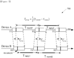
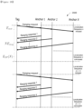
- FIGURE 7 illustrates an example double-sided two-way ranging with three messages 700 according to embodiments of the present disclosure.
- the embodiment of the double-sided two-way ranging shown in FIGURE 7 is for illustration only.
- One or more of the components illustrated in FIGURE 7 can be implemented in specialized circuitry configured to perform the noted functions or one or more of the components can be implemented by one or more processors executing instructions to perform the noted functions.
- the double-sided two-way ranging with three messages 700 may be performed in the electronic device 501 as illustrated in FIGURE 5 .
- FIGURE 7 DS-TWR with three messages is illustrated in FIGURE 7 , which reduces the estimation error induced by clock drift from long response delays.
- Device A is the initiator to initialize the first round-trip measurement
- device B as the responder, responses to complete the first round-trip measurement, and meanwhile initialize the second round-trip measurement.
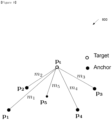
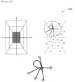
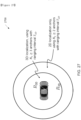
- FIGURE 8 illustrates an example localization of tag 800 based on range measurements from anchors according to embodiments of the present disclosure.
- the embodiment of the localization of tag 800 shown in FIGURE 8 is for illustration only.
- One or more of the components illustrated in FIGURE 8 can be implemented in specialized circuitry configured to perform the noted functions or one or more of the components can be implemented by one or more processors executing instructions to perform the noted functions.
- FIG. 4 An exemplary setup for localization of a tag based on range measurements from anchors is shown in Figure 4 .
- the tag (or target) location p t ( x t , y t , z t ) is to be estimated.
- two out of three coordinates, such as just ( x t , y t ) are estimated.
- the i th anchor performs a measurement m i on the tag, where m's can be range measurements. Localization schemes typically attempt to perform the inverse mapping from the measurements to the location of the target.
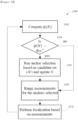
- Localization result can be generated or calculated for each time instance where the range measurements from the anchors are available. This can result in frequent localization processing if the range measurements from anchors are updated frequently. Frequent localization may not be necessary if the result of the localization does not trigger any action for the applications that make use of the localization results, which can be the case if the location of the target is outside of the region of interest for possible action, or if the localization result may be considered inaccurate or unreliable which can be the case if the target is too far from the anchors.
- a cell or grid based localization method which takes ranging measurements and anchor location as inputs and generates the location of the target in terms of the cell or the state of the target with a certain confidence measure.
- a cell is essentially a specific localization space or region of interest. A certain action can be triggered when the method identifies that the target is in the space with sufficiently high confidence.
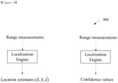
- FIGURE 9 illustrates an example two localization engine frameworks 900 according to embodiments of the present disclosure.
- the embodiment of the two localization engine frameworks 900 shown in FIGURE 9 is for illustration only.
- One or more of the components illustrated in FIGURE 9 can be implemented in specialized circuitry configured to perform the noted functions or one or more of the components can be implemented by one or more processors executing instructions to perform the noted functions.
- FIGURE 9 shows two different localization frameworks, where the framework on the right is the focus of this disclosure. Although range measurement is shown in FIGURE 9 , it is noted that other types of measurements, such as time difference of arrival, angle of arrive, time of arrival can also be applied for the framework.
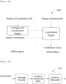
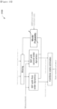
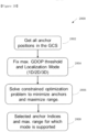
- FIGURE 10 illustrates an example localization engine architecture 1000 according to embodiments of the present disclosure.
- the embodiment of the localization engine architecture 1000 shown in FIGURE 10 is for illustration only.
- One or more of the components illustrated in FIGURE 10 can be implemented in specialized circuitry configured to perform the noted functions or one or more of the components can be implemented by one or more processors executing instructions to perform the noted functions.
- FIGURE 10 An example architecture of the localization engine is as shown in FIGURE 10 .
- the methods of constructing the target state space, applying state transition, computation of the cell likelihood and the corresponding state likelihood are described in this disclosure. Construction of the target state space and the state transition can be included in the "configure the localization engine” block, while the computation of the cell and/or state likelihood based on measurements can be performed in the "localization engine” block.
- n ⁇ n adjacency matrix A ( G ) contains the adjacency relationships between the vertices, where the entry on the i-th row and j-th column, denoted by A ( G ) i,j , is 1 if ( i, j ) ⁇ E and 0 otherwise.
- the neighborhood of a vertex v is denoted as ( v ) which is the collection of vertices which are adjacent to v.
- self-localizable mobile devices are considered and methods for performing the on-device localization using the range measurements from the anchors are described.
- Other types of measurements such as time difference of arrival, angle of arrive, time of arrival can also be applied with our framework with straightforward modifications.
- the localization methods can also be executed at the anchors or at a central unit controlling the anchors.
- the mobile device also called the target or tag
- the mobile device is assumed to move in a region that defines the kinematic region of interest for this problem.
- the region may have boundaries defined in terms of bounds on spatial coordinates.
- Examples of are room, gallery, hallway, vicinity and inside of a car etc.
- the tracking problem becomes the estimation of the state of that target (possible state definitions of the target are provided later).
- the method can be easily extended to multiple-target tracking case which can be viewed as a set of single target tracking methods operating in parallel.
- This state space may be specified with a target/tag state graph ( G S ) where each node corresponds to a state and each edge denotes a state transition which is associated with certain probability ( q ( s , s ')), known as state transition probability.
- the state space may vary from problem to problem depending on the nature of the target to be tracked and the sensor (or other) information to be received.
- FIGURE 11 illustrates an example construct state transition graph 1100 from the environment according to embodiments of the present disclosure.
- the embodiment of the construct state transition graph 1100 shown in FIGURE 11 is for illustration only.
- One or more of the components illustrated in FIGURE 11 can be implemented in specialized circuitry configured to perform the noted functions or one or more of the components can be implemented by one or more processors executing instructions to perform the noted functions.
- the construction of the state-space is highly non-trivial and problem specific.
- Two schemes are provided to formulate the state-space for the localization engine. The basic steps are illustrated in FIGURE 11 . The design of the other components of the localization engine can closely depend on the choice of these schemes.
- the first step is to tessellate into a finite set of cells (also known as grids) indexed by 1...., m where c 1 , ... , c M denotes the centroids of the cells.
- localization is considered in a subset of a two-dimensional space (i.e., is a bounded subset of a plane).
- the construction can be extended to higher dimensions such as three dimensions.
- the cells can be any convex polygon including but not limited to hexagonal and square lattices and Voronoi tessellation. Different cell can have different shapes and sizes.
- the definition of the adjacency matrix of G C (equivalently the definition of E C ) can be design specific.
- One example construction is to define adjacency according to the Delaunay triangulation formed by the nodes of V C .
- FIGURE 12 illustrates an example constructing connectivity graph 1200 from the grid world for a 2D scenario according to embodiments of the present disclosure.
- the embodiment of the constructing connectivity graph 1200 shown in FIGURE 12 is for illustration only.
- One or more of the components illustrated in FIGURE 12 can be implemented in specialized circuitry configured to perform the noted functions or one or more of the components can be implemented by one or more processors executing instructions to perform the noted functions.
- G C As illustrated in FIGURE 12 , an example construction of G C is provided where two nodes are adjacent if and only if the grids share a common edge.
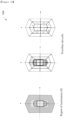
- FIGURE 13 illustrates an example constructing connectivity graph 1300 from the grid world for a 2D scenario for car access according to embodiments of the present disclosure.
- the embodiment of the constructing connectivity graph 1300 shown in FIGURE 13 is for illustration only.
- One or more of the components illustrated in FIGURE 13 can be implemented in specialized circuitry configured to perform the noted functions or one or more of the components can be implemented by one or more processors executing instructions to perform the noted functions.
- the region of localization can be the space surrounding a car as shown in left most figure in FIGURE 13 .
- the region can be tessellated into cells as shown in the middle and right most figures in FIGURE 13 .
- the physical interpretation of each cell label is shown in TABLE 1.
- a cell can represent a physical space inside or outside the car.
- the cells within the car can be defined to be corresponding to the seats in the car (cell 1, 2, 3, 4).
- the cells of possibly different shapes and sizes can be designed such that the localization of the target (i.e. identification of the cell in which the target is located) can trigger a subsequent action, e.g. in the upper layer, based on the localization result.
- a cell can cover the approximately 2 meters radius from the car door outside of the car (cell 12 as illustrated in FIGURE 13 ), with the purpose of unlocking the car when the tag is localized to be in the cell.
- Another cell can cover the space corresponding to the driver seat inside the car (cell 1 as illustrated in FIGURE 13 ), with the purpose of starting the car engine when the tag is localized to be in the cell.
- TABLE 1 Cell labels C ells Description 1 Inside car (front left) 2 Insider car (front right) 3 Inside car (back right) 4 Inside car (back left) 5 Front left door 6 Car front 7 8 Front right door 9 Back right door 1 0 Car back 11 1 2 Back right door ⁇ 13 Far away regions
- the target state graph can be constructed by following either of the two following schemes. Note that these two schemes may not be the only way of constructing the target state graph. For example, there can be hybrid schemes combining scheme 1 and scheme 2 for formulating the target state graph.
- the target state graph G S is not same as the connectivity graph.
- One way to construct such a target state graph is to utilize the heading of the target.
- FIGURE 14 shows why G S ⁇ G C for a target motion with certain heading direction (which is likely the case when the target or equivalently the mobile device is held at hand or kept in pocket or bag and the person is walking in ).
- FIGURE 14 illustrates an example target state graph 1400 to capture information on target's heading (scheme 2) according to embodiments of the present disclosure.
- the embodiment of the target state graph 1400 shown in FIGURE 14 is for illustration only.
- One or more of the components illustrated in FIGURE 14 can be implemented in specialized circuitry configured to perform the noted functions or one or more of the components can be implemented by one or more processors executing instructions to perform the noted functions.
- the construction of G S from G C is illustrated in FIGURE 15 .
- FIGURE 15 illustrates an example construction of target state graph 1500 from connectivity graph according to embodiments of the present disclosure.
- the embodiment of the construction of target state graph 1500 shown in FIGURE 15 is for illustration only.
- One or more of the components illustrated in FIGURE 15 can be implemented in specialized circuitry configured to perform the noted functions or one or more of the components can be implemented by one or more processors executing instructions to perform the noted functions.
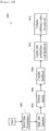
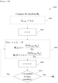
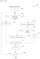
- FIGURE 16 shows the main blocks of the localization engine.
- FIGURE 16 illustrates an example localization engine 1600 according to embodiments of the present disclosure.
- the embodiment of the localization engine 1600 shown in FIGURE 16 is for illustration only.
- One or more of the components illustrated in FIGURE 16 can be implemented in specialized circuitry configured to perform the noted functions or one or more of the components can be implemented by one or more processors executing instructions to perform the noted functions.
- the localization engine 1600 calculates an initial state probabilities in block 1602, applies state transition in block 1604, performs ranging operation in block 1606, computes likelihood in block 1608, updates state probabilities with likelihood block in block 1610, and computes confidence values for each cells in block 1612.
- the localization engine 1600 further applies state transition in block 1604 after computing confidence values for each cell in block 1612.
- FIGURE 16 The block "apply state transition” in FIGURE 16 (e.g., 1604) is described. Note that this block can be designed offline and may not need to be updated during the online process of localization.
- s' ) denotes the probability of transition from state s ' to s .
- the state transition probabilities can be interpreted as weights on the directed graph G S . Note that the assignment of state transition probabilities follows some assumption on the target motion (which may be specified in terms of a target motion model).
- this construction is related to the target state graph construction scheme which encodes the current and the previous cell of the target in one state.
- the state construction in this way enables us to model the heading of target's motion.
- s is a rest state
- the heading angle is undefined.
- p ( s ) there is a probability p ( s ) for all dynamic states indicating the probability to transition to a rest state.
- s ') is equal to p s , if s ' is a rest state, (1 - p s ) w ( s , s '), if s ' is not a rest state and s belongs to the neighborhood of s (i.e. s ⁇ ( s' )) in G S , and 0 otherwise.
- the state transition probabilities are used to update the state probabilities using the following pseudocode as shown in TABLE 2.
- the present disclosure relates to the blocks “compute likelihood (e.g., 1608)" and “update state probabilities with likelihood” (e.g., 1610) in FIGURE 16 .
- the block “compute likelihood” can be elaborated as the block diagram in FIGURE 17 .
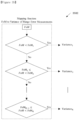
- FIGURE 17 illustrates an example computation of the state likelihoods 1700 according to embodiments of the present disclosure.
- the embodiment of the computation of the state likelihoods 1700 shown in FIGURE 17 is for illustration only.
- One or more of the components illustrated in FIGURE 17 can be implemented in specialized circuitry configured to perform the noted functions or one or more of the components can be implemented by one or more processors executing instructions to perform the noted functions.
- Y k be the set of range measurements available at time t k .
- y k denote a value of the random variable Y k .
- Other types of measurements such as time difference of arrival, angle of arrival, time of arrival, etc. can also be used as inputs with the appropriate mapping or function from the measurements and the anchor locations to the target location.
- the present disclosure provides a method of constructing the likelihood function from the range measurements.
- the target location is a non-linear function of the anchor locations and range measurements. This non-linearity can be taken into account during the formulation of the likelihood function. Note that given any error distribution, one can formulate the likelihood function from the joint probability distribution of the measurement errors.
- f ( x, y, z ) ( x ⁇ x a i ⁇ 2 + ( y ⁇ y a i ) 2 + z ⁇ z a i 2 ) 1 2 T .
- x a i , y a i , z a i denotes the coordinates of the i-th anchor.
- the above likelihood function is evaluated by the computation of the numerical integration.
- the next step is to compute the likelihood of each state in the target state graph.
- the cell likelihoods are directly translated into state likelihoods.
- the following pseudocode converts the cell-likelihoods to state-likelihoods as shown in TABLE 3.
- step 3 is the normalization step used to convert the state confidence values to valid state probability values such that the sum of the state probabilities is unity, as shown in TABLE 4.
- the confidence of each state is used to compute the cell confidence values which are output of the localization engine at each iteration.
- the cell confidence values are equal to the state confidence values.
- the cell confidence values are computed according to the following pseudocode as shown in TABLE 5.
- the final decision on the state (or a subset of it) at any given time can be obtained from the state with the largest state probabilities at the time, or a weighted average of the state according to the state probabilities at the time.
- Extended Kalman filter can be used to estimate and track the position of a tag based on the range measurements from the tag to multiple anchors.
- An EKF algorithm assumes a dynamic model for the tag.
- the dynamic model provides prediction to the trajectory of the tag according to the model, and the algorithm uses measurements to correct the prediction and generate a location estimate of the tag.
- one EKF model may produce a better localization and tracking result compared to another EKF model.
- localization and tracking solutions which can adapt to multiple EKF models are described.
- FIGURE 18 illustrates an example EKF models 1800 according to embodiments of the present disclosure.
- the embodiment of the EKF models 1800 shown in FIGURE 18 is for illustration only.
- One or more of the components illustrated in FIGURE 18 can be implemented in specialized circuitry configured to perform the noted functions or one or more of the components can be implemented by one or more processors executing instructions to perform the noted functions.
- FIGURE 18 shows two example EKFs with two different dynamic models, namely EKF with first order dynamics, and EKF with second order dynamics. More generally, there can be M dynamic models.
- This disclosure provides methods to adapt to multiple EKF models. The methods include methods to mix the state estimates of the EKF, methods to perform model update, methods to compute model likelihood and methods to combine state estimates. This disclosure also provides methods to adjust or adapt model likelihood based on other inputs.
- KF/EKF with first order dynamics as process with 3 states may provide better localization and tracking.
- the second order dynamics with 6 states may provide better localization and tracking.
- the accuracy of localization and tracking could reduce.
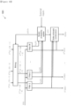
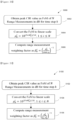
- FIGURE 19 illustrates an example M parallel EKF with multiple mixture models of dynamics 1900 according to embodiments of the present disclosure.
- the embodiment of the M parallel EKF with multiple mixture models of dynamics 1900 shown in FIGURE 19 is for illustration only.
- One or more of the components illustrated in FIGURE 19 can be implemented in specialized circuitry configured to perform the noted functions or one or more of the components can be implemented by one or more processors executing instructions to perform the noted functions.
- FIGURE 19 shows (1) multiple models with an EKF for each model (labeled as "model"), (2) model probability evaluator, (3) a mixer at the input of each EKF, and (4) an estimate combiner as the output of each EKF.
- the state estimates of the previous time step ( X 1 , ... , X M ) is the input to the mixer, which computes the initial mixed state estimates for the filters, denoted as ( X 01 , ... , X 0 M ) .
- the filters output the next state estimate ( X 1 , ... , X M ) and the model likelihood ( ⁇ 1 , ... , ⁇ M ).
- FIGURE 20 illustrates an example Markov chain for model switching 2000 according to embodiments of the present disclosure.
- the embodiment of the Markov chain for model switching 2000 shown in FIGURE 20 is for illustration only.
- One or more of the components illustrated in FIGURE 20 can be implemented in specialized circuitry configured to perform the noted functions or one or more of the components can be implemented by one or more processors executing instructions to perform the noted functions.
- the state estimate combiner combines the outputs of M filters and provides the final mixed state estimate.
- r k- 1 j )
- r k i ).
- the model transition probability p ( i, j ) can be updated or adapted based on other observations/measurements/information. This corresponds to one example of the additional inputs to the model probability update as shown in FIGURE 21 .
- the model transition probability update can depend on whether one or more measurement loss or partial measurement loss (e.g. range measurement between the tag and an anchor) has occurred. If there is no (partial) measurement loss, the model transition probability can be of one configuration; else if there is (partial) measurement loss, a model can be chosen or favored.
- FIGURE 21 illustrates an example mixture with two EKF models 2100 according to embodiments of the present disclosure.
- the embodiment of the mixture with two EKF models 2100 shown in FIGURE 21 is for illustration only.
- One or more of the components illustrated in FIGURE 21 can be implemented in specialized circuitry configured to perform the noted functions or one or more of the components can be implemented by one or more processors executing instructions to perform the noted functions.
- FIGURE 21 shows a special case of FIGURE 19 , corresponding to the case with two EKF models.
- the first order dynamics is chosen for EKF when there is a (partial) measurement loss; else the model transition probability remains the same.
- a localization system using wireless sensor network where the sensors (anchors) measure the distances of the tag from the anchors (also known as ranges) and relay the measurements to the tag over wireless communication channel. As these measurements are subj ected to sensing errors, the tag obtains an estimate of the true value of the physical quantity.
- One way of increasing this estimation accuracy at the tag is to connect to more number of anchors (possibly all) in the network.
- this may not be a feasible or desirable option as the connection to more number of nodes increases the operation cost (e.g. scheduling overhead and other metrics).
- it is important to design an optimal/near-optimal strategy/algorithm that may enable the anchor selection to achieve a target accuracy under the minimum cost.
- An application of this algorithm is the autonomous node selection (ANS) in indoor localization, where the ANS may decide the set of anchors with minimum connection cost which may ensure a target estimation accuracy.
- each sensor alternatively referred to as anchor in the network is capable of measuring the distance of the target (also known as range measurements) and sending the range measurements to the target over wireless communication channels. Based on the estimated location based on the range measurements, the target uses the method to determine the anchors from which the target may actively collect measurements to achieve a certain target estimation accuracy.
- a localization system based on a wireless sensor network of anchors can been deployed to collect range measurements of a target.
- Each anchor in this network as well as the target can be enabled with a computer to process data and a two-way radio to share information, a battery to provide power.
- the range measurements can be sent by the anchors to the target by a wireless communication channel after some periodic/aperiodic time intervals. After the completion of one reporting cycle where all the active anchors have sent their most recent range measurements, a measurement report can be constructed at the target by concatenating all the measurements in one reporting cycle.
- a tracking algorithm can run in the target's computer and collects the measurement reports to estimate the target's location with respect to a global coordinate system (GCS).
- GCS global coordinate system
- the tracking algorithms are least-squares, and any Bayesian filtering methods (e.g., Kalman and extended Kalman filters).
- the target may decide to select a new set of active anchors within the communication range which may perform ranging.
- Each anchor can know the location with respect to the GCS.
- the target can acquire the locations of the anchors upon request at the beginning of the activation cycle.
- a resource management method is introduced which allows the target to select the set of active anchors for each activity cycle.
- the localization system as described is an example system where the method can be applicable.
- Other systems are also possible, where the anchor selection and/or tag location tracking can be performed by one or more of the anchors, or by a centralized control unit connected with the anchors, when the information as described in the disclosure to carry out the operation is available at the unit performing the operation.
- FIGURE 22A illustrates an example static anchor selection 2200 according to embodiments of the present disclosure.
- the embodiment of the static anchor selection 2200 shown in FIGURE 22A is for illustration only.
- One or more of the components illustrated in FIGURE 22A can be implemented in specialized circuitry configured to perform the noted functions or one or more of the components can be implemented by one or more processors executing instructions to perform the noted functions.
- the method in this embodiment can be used to determine the set of active anchors from a set of candidate anchors available in the network which satisfies a set of criteria/objectives.
- This method can be applied to a one-off (static) or semi-static anchor selection system as shown in FIGURE 22A , where anchor selection is performed in the beginning of the ranging/localization session and may not be performed during the current ranging/localization session. It can also be applied to a more dynamic/adaptive anchor selection system as shown in FIGURE 22B , where anchor selection (if assessed to be needed/desired) can be triggered for time interval similar to ranging or localization time interval.
- FIGURE 22B illustrates an example dynamic anchor selection 2250 according to embodiments of the present disclosure.
- the embodiment of the dynamic anchor selection 2250 shown in FIGURE 22B is for illustration only.
- One or more of the components illustrated in FIGURE 22B can be implemented in specialized circuitry configured to perform the noted functions or one or more of the components can be implemented by one or more processors executing instructions to perform the noted functions.
- the target acquires the locations from the candidate anchors in .
- the target has an estimate of the location as x ⁇ t which can be obtained by the location estimation computed at the previous time step (when t > 0) or acquired from the latest estimated location available after the completion of the previous activity cycle.
- Q is the measurement error covariance
- the metric of interest can be a scalar function of M ( ) , denoted as ⁇ ( M ( )) .
- a low ⁇ ( M ( )) value implies better localization performance.
- An example of the metric of interest is the estimated geometric dilution of precision (GDOP).
- J x ⁇ t ( ) is constructed by stacking the rows indexed by N from J x ⁇ t defined in equation (2).
- Equation (5) c(N) is a cost function associated with the subset N and ⁇ 0 is a predetermined estimation accuracy threshold.
- An example cost function can just be the number of anchors to be selected. If the estimation accuracy cannot be satisfied, anchor selection can indicate selection of all candidate anchors or can indicate infeasible outcome.
- the algorithm to execute equation (5) can be done with steps below as shown in TABLE 7.
- the anchor selection procedure can be triggered when the estimation accuracy of the current set of anchors is worse than a certain threshold ⁇ th , This can occur due to the movement of the tag, or in case of mobile/portable anchors, movement of one or more anchors.
- ⁇ th can be the same as ⁇ 0, or ⁇ th can include a hysteresis margin with respect to ⁇ 0, such that ⁇ th > ⁇ 0 .
- FIGURE 23 illustrates an example adaptive anchor selection process 2300 according to embodiments of the present disclosure.
- the embodiment of the adaptive anchor selection process 2300 shown in FIGURE 23 is for illustration only.
- One or more of the components illustrated in FIGURE 23 can be implemented in specialized circuitry configured to perform the noted functions or one or more of the components can be implemented by one or more processors executing instructions to perform the noted functions.
- FIGURE 23 An example procedure of adaptive anchor selection is shown in FIGURE 23 .
- the metric for estimation accuracy ⁇ ( N ) is calculated in step 2302 based on the current set of active anchors and the current estimate of the tag location (which can be obtained from previous tag localization result). If accuracy is estimated to become worse than a threshold ⁇ th in step 2304, the anchor selection procedure is triggered in step 2308, else the current set of active anchors can be retained for subsequent ranging and localization. If the anchor selection procedure is triggered, the current set of active anchors for ranging is updated with the new set generated by the anchor selection in step 2306. The next round of ranging measurement and localization are then performed with the new set of active anchors in step 2310. The localization results as well as the anchors selected are used to compute the next ⁇ ( N ) for the next round of adaptation.
- FIGURE 24 illustrates an example adaptive anchor selection system 2400 according to embodiments of the present disclosure.
- the embodiment of the adaptive anchor selection system 2400 shown in FIGURE 24 is for illustration only.
- One or more of the components illustrated in FIGURE 24 can be implemented in specialized circuitry configured to perform the noted functions or one or more of the components can be implemented by one or more processors executing instructions to perform the noted functions.
- the construction of the set of active anchors for one activity cycle can be divided into two stages as follows.
- an algorithm in this stage picks up a set of nodes ⁇ based on some quality metric (e.g., received signal strength).
- some quality metric e.g., received signal strength
- the LAS chooses ⁇ .
- FIGURE 25 illustrates an example global and local anchor selection 2500 according to embodiments of the present disclosure.
- the embodiment of the global and local anchor selection 2500 shown in FIGURE 25 is for illustration only.
- One or more of the components illustrated in FIGURE 25 can be implemented in specialized circuitry configured to perform the noted functions or one or more of the components can be implemented by one or more processors executing instructions to perform the noted functions.
- the two-stage process is as shown FIGURE 25 .
- the target needs to acquire the location information of all the anchors through signaling with the sensor network.
- GAS can be used to reduce this signaling overhead at the beginning of each activity cycle.
- the algorithm for LAS can be performed with the steps below as shown in TABLE 8.
- the cost function as shown in equation (5) can be the energy expended in various parts of the localization process. There can be three components of energy consumption in a localization framework.
- energy expended for ranging initiation ( E init ) is provided.
- energy consumed for message passing ( E msg ) is provided.
- E msg energy consumed for message passing
- energy spent for computations and signal processing ( E SP ) in the ranging/localization unit of the tag is provide.
- FIGURE 26 illustrates an example schematic of localization sequence and energy consumption model per ranging interval 2600 according to embodiments of the present disclosure.
- the embodiment of the schematic of localization sequence and energy consumption model per ranging interval 2600 shown in FIGURE 26 is for illustration only.
- One or more of the components illustrated in FIGURE 26 can be implemented in specialized circuitry configured to perform the noted functions or one or more of the components can be implemented by one or more processors executing instructions to perform the noted functions.
- FIGURE 26 shows an example localization procedure initiated by a tag (of unknown location), trying to locate itself using ranging measurements with N anchors (of known location).
- the energy spent to transmit the ranging requests ( E init ) is independent of the number of anchors.
- Receiving the ranging responses with the ranging data from each anchor consumes an energy of E msg per response.
- the anchor selection can take into account the desirable/required localization format/metrics, such as the localization dimensions.
- An example localization format/metric is 2D or 3D localization result, and more specifically (X, Y), or (X, Z), or, (Y, Z), or (X, Y, Z) localization. This is because the number of anchors as well as the metric ⁇ ( N ) depends on the localization format/metric.
- the desired/required localization format/metric can change depending on various factors. One factor is the current condition of the tag, such as the position of the tag within the localization region of interest.
- FIGURE 27 illustrates an example transition between localization modes 2700 based on range according to embodiments of the present disclosure.
- the embodiment of the transition between localization modes 2700 shown in FIGURE 27 is for illustration only.
- One or more of the components illustrated in FIGURE 27 can be implemented in specialized circuitry configured to perform the noted functions or one or more of the components can be implemented by one or more processors executing instructions to perform the noted functions.
- FIGURE 27 An example of how the number of anchors desired/required can change is shown in FIGURE 27 for a car access use case where the localization mode (i.e., 2D or 3D localization) and hence the number of anchors required changes with respect to the range of the tag from the car.
- the localization mode i.e., 2D or 3D localization
- FIGURE 28 An example procedure to determine the range thresholds/boundaries to change localization mode is provided in FIGURE 28 .
- FIGURE 28 illustrates a flow chart of a method 2800 for determining range thresholds to change the localization mode according to embodiments of the present disclosure.
- the embodiment of the method 2800 shown in FIGURE 28 is for illustration only.
- One or more of the components illustrated in FIGURE 28 can be implemented in specialized circuitry configured to perform the noted functions or one or more of the components can be implemented by one or more processors executing instructions to perform the noted functions.
- the method 2800 comprises in step 2802 getting all anchor positions in the GCS, fixing in step 2804 maximum GDOP threshold and localization mode (1D/2D/3D), solving in step 2806 constrained optimization problem to minimize anchors and maximize range, and identifying in step 2808 selected anchor indices and maximum range for which mode is supported.
- Localization result can be generated or calculated for each time instance where the range measurements from the anchors are available.
- the quality of measurements including range, angle-of-arrival (AOA) can have impact on the localization accuracy. Therefore, solutions to enable the localization engine/system to take into account the quality of measurements can be beneficial.
- the time of flight (ToF) based range measurements and angle of arrival (AoA) measurements are prone to measurement errors. These errors arise due to various reasons including but not limited to environmental factors, device limitations, interference, signal power, etc. Localization of a "tag" device (other names are not precluded) requires range and/or AoA measurements from multiple anchors. Given the anchor locations and sufficient number of range and/or AoA measurements, the location of the device can be obtained after performing some computations. Erroneous range and AoA measurements result in erroneous localization.
- Devices that measure ranges and AoA also may report the confidence of the measured range and AoA.
- the confidence of the measured range or AoA can be reported many forms or metrics including but not limited to whether the signal path is line of sight (LoS), received signal strength (RSS), RSS Indicator, peak value of correlation of a known codeword such as a preamble, one or more values of the channel impulse response (CIR), CIR with timing information, a statistical measure of CIR among others.
- FIGURE 29 illustrates an example incorporating confidence of range and AoA measurements 2900 in localization and tracking system according to embodiments of the present disclosure.
- the embodiment of the incorporating confidence of range and AoA measurements 2900 shown in FIGURE 29 is for illustration only.
- One or more of the components illustrated in FIGURE 29 can be implemented in specialized circuitry configured to perform the noted functions or one or more of the components can be implemented by one or more processors executing instructions to perform the noted functions.
- the localization and tracking system can be tuned based on the metrics that indicate the confidence of range and/or AoA measurements to improve the accuracy.
- the confidence of these measurements can be used to modify the parameters of localization and tracking system in many ways including but not limited to tuning the statistical error variance of one of more range measurements, discarding one or more range/AoA measurements, weighting the range/AoA measurements before inputting to the localization system, etc.
- the present disclosure describes methods to take into account measurement quality and/or measurement loss in generating localization result.
- the figure of merit (FoM) or the confidence of range and AoA measurements can be indicated.
- the confidence of range measurement or AoA measurements (e.g., figure of merit) conveys a quantification of the accuracy of range or angle measurements.
- the term FoM is used to refer to this quantification of accuracy of range and/or angle measurements. Other terms conveying the same are not precluded.
- the FoM can be reported as the peak value of the CIR.
- CIR may be obtained after correlating the received signal with a local copy of the same signal for a certain predefined duration.
- the resulting peak may be used to indicate the confidence in the range measurement, or the figure of merit, denoted as FoM in decibel (dB) scale.
- FoM figure of merit
- ⁇ i 10 FoMi /10 for sensor (or anchor or beacon, other terms not precluded) i , 1 ⁇ i ⁇ N.
- Weighting can be obtained in many ways including but not limited to the following.
- FoM may be normalized with the maximum value across all sensors as shown in FIGURE 30 and max ⁇ can be determined based the methods: the max ⁇ is the maximum value of FoM across all sensors until time step k ; and the max ⁇ is the maximum value of FoM across all sensors only at step k.
- FIGURE 30 illustrates a flowchart of a method 3000 for obtaining the weighting factor from FoM indicated by CIR peak by normalizing with the maximum value according to embodiments of the present disclosure.
- the embodiment of the steps to obtain the method 3000 shown in FIGURE 30 is for illustration only.
- One or more of the components illustrated in FIGURE 30 can be implemented in specialized circuitry configured to perform the noted functions or one or more of the components can be implemented by one or more processors executing instructions to perform the noted functions.
- the method 3000 comprises: obtaining in step 3002 peak CIR value as FoM of N range measurements in dB for time step k; converting in step 3004 the FoM to linear scale; and computing in step 3006 range measurement weighting factor.
- FIGURE 31 illustrates an example of a method 3100 to obtain the weighting factor from FoM indicated by CIR peak by weighted average of a function of FoM according to embodiments of the present disclosure.
- the embodiment of the method 3100 to obtain the weighting factor shown in FIGURE 31 is for illustration only.
- One or more of the components illustrated in FIGURE 31 can be implemented in specialized circuitry configured to perform the noted functions or one or more of the components can be implemented by one or more processors executing instructions to perform the noted functions.
- Weighted average of FoM values can be used as shown in FIGURE 31 .
- the method 3100 comprises: obtaining in step 3102 peak CIR value as FoM of N range measurements in dB for time step k; converting in step 3104 the FoM to linear scale; and computing in step 3106 range measurement weighting factor.
- FIGURE 32 illustrates a flowchart of a method 3200 for obtaining the weighting factor from FoM indicated by CIR peak by weighted average with memory according to embodiments of the present disclosure.
- the embodiment of the method 3200 to obtain the weighting factor shown in FIGURE 32 is for illustration only.
- One or more of the components illustrated in FIGURE 32 can be implemented in specialized circuitry configured to perform the noted functions or one or more of the components can be implemented by one or more processors executing instructions to perform the noted functions.
- Weighted average with memory is illustrated in FIGURE 32 .
- the method 3200 comprises: obtaining in step 3202 peak CIR value as FoM of N range measurements in dB for time step k; converting in step 3204 the FoM to linear scale; computing in step 3206; and computing in step 3208 range measurement weighting factor.
- first peak and highest peak value of the channel impulse response is provided.
- FIGURE 33 illustrates an example computing delay spread estimate 3300 with FoM of first peak and highest peak according to embodiments of the present disclosure.
- the embodiment of the computing delay spread estimate 3300 shown in FIGURE 33 is for illustration only.
- One or more of the components illustrated in FIGURE 33 can be implemented in specialized circuitry configured to perform the noted functions or one or more of the components can be implemented by one or more processors executing instructions to perform the noted functions.
- FoM of the first path FoM of the main path (highest peak) and the taps/difference between the two (and the resolution of the taps) may help in getting a coarse estimate of channel delay spread.
- FIGURE 33 which shows the computation of delay spread estimate with the FoM of first peak and highest peak of the channel impulse response.
- the delay spread estimate could be directly used to obtain range measurement bias or error statistics.
- One way to obtain this is by approximating the range measurement bias as an exponential distribution whose parameter is the computed the delay spread estimate or a function of the delay spread estimate. This is used to obtain a weighting factor for the range measurement error.
- channel impulse response as FoM is provided.
- the channel impulse response (CIR) can be used to get an estimate of the delay spread.
- FIGURE 34 illustrates an example obtaining range measurement bias or error statistics using CIR 3400 according to embodiments of the present disclosure.
- the embodiment of the obtaining range measurement bias or error statistics using CIR 3400 shown in FIGURE 34 is for illustration only.
- One or more of the components illustrated in FIGURE 34 can be implemented in specialized circuitry configured to perform the noted functions or one or more of the components can be implemented by one or more processors executing instructions to perform the noted functions.
- Delay spread can be used to classify LOS and NLOS measurements.
- the delay spread estimate could be directly used to obtain range measurement bias or error statistics.
- One way to obtain this is by approximating the range measurement bias as an exponential distribution whose parameter is the computed with the delay spread estimate or a function of the delay spread estimate. This is used to obtain a weighting factor for the range measurement error as shown in FIGURE 34 .
- test statistics like kurtosis or skewness of the CIR may be used to infer if the measurement channel is LOS or NLOS. These test statistics are used to map CIR to FoM.
- received signal strength measurements are provided.
- Received signal strength measurement can be used as FoM to obtain an estimate of the signal-to-noise ratio (SNR), for a given receiver noise floor.
- SNR signal-to-noise ratio
- mapping FoM to variance of error measurement is provided.
- FIGURE 35 illustrates an example mapping function between FoM and variance of range measurement errors 3500 according to embodiments of the present disclosure.
- the embodiment of the mapping function between FoM and variance of range measurement errors 3500 shown in FIGURE 35 is for illustration only.
- One or more of the components illustrated in FIGURE 35 can be implemented in specialized circuitry configured to perform the noted functions or one or more of the components can be implemented by one or more processors executing instructions to perform the noted functions.
- FoM or a function of FoM obtained via any scheme can be mapped to a discrete set of variance of range measurement errors using a mapping function.
- An example of a mapping is shown in FIGURE 35 . This mapping is further used to generate the weighting factor for range measurements to be used in localization and tracking system.
- localization and tracking using confidence of range measurements is provided.
- FIGURE 36 illustrates an example diagrammatic representation of localization with modified extended Kalman filter 3600 according to embodiments of the present disclosure.
- the embodiment of the diagrammatic representation of localization with modified extended Kalman filter 3600 shown in FIGURE 36 is for illustration only.
- One or more of the components illustrated in FIGURE 36 can be implemented in specialized circuitry configured to perform the noted functions or one or more of the components can be implemented by one or more processors executing instructions to perform the noted functions.
- FoM information is incorporated in the Kalman filter as shown in FIGURE 36 . While the scheme described is for extended Kalman filter, other realizations of Kalman filter with or without additional processing blocks in cascade including but not limited to non-linear least squares, incorporating confidence of range measurements localization and tracking are not precluded.
- R is the measurement error covariance matrix. Typically, R is a diagonal matrix (unless errors between two sensors are correlated.
- ⁇ t be a vector of weighting factor denoting an either an estimate or a function of the measurement error. If instantaneous error, v k is known at each measurement, then the weighting factor may be absolute or square of the instantaneous error. If a function f ( v t ) is known, then ⁇ k can accordingly represent the same.
- A is is the state transition model of the extended Kalman filter for 3D or 2D localization
- P is the prediction error covariance matrix
- Q is the process noise covariance
- H is the Jacobian matrix
- x aj is the 3D vector of anchor j location
- K is known as the Kalman gain.
- d j x ⁇ x j 2 + y ⁇ y j 2 + z ⁇ z j 2 .
- f x ⁇ t + x a j d j .
- Range measurements are erroneous and, in some cases, may not render any measurement for one or more ranges. Range measurements from one or more anchors may be discarded if the range measurements are unusable for any reason including but not limited to errors in measurements, loss of measurement data, no measurement available, etc., as shown in FIGURE 37 . Such cases are referred as partial measurement loss (other references to the same are not precluded).
- FIGURE 37 illustrates an example range measurement with partial measurement loss 3700 for a localization and tracking system according to embodiments of the present disclosure.
- the embodiment of the range measurement with partial measurement loss 3700 shown in FIGURE 37 is for illustration only.
- One or more of the components illustrated in FIGURE 37 can be implemented in specialized circuitry configured to perform the noted functions or one or more of the components can be implemented by one or more processors executing instructions to perform the noted functions.
- the localization and tracking system are designed to be capable of handling such partial measurement losses.
- An example of such a localization system using extended Kalman filter is described in the mentioned embodiments (e.g., S6). While the scheme described is for extended Kalman filter, other realizations of Kalman filter with or without additional processing blocks in cascade including but not limited to non-linear least squares, employing partial measurement loss of range measurements localization and tracking are not precluded.
- FIGURE 38 illustrates a flow chart of a method 3800 for extended Kalman filter with partial measurement loss according to embodiments of the present disclosure.
- the embodiment of the method 3800 shown in FIGURE 38 is for illustration only.
- One or more of the components illustrated in FIGURE 38 can be implemented in specialized circuitry configured to perform the noted functions or one or more of the components can be implemented by one or more processors executing instructions to perform the noted functions.
- the method 3800 begins at step 3802.
- step 3804 the method determines whether stopping criterion is reached.
- step 3804 if yes, the method 3800 stops in step 3806.
- step 3804 if no, the method 3800 performs step 3808.
- step 3808 the method 3800 performs a prediction.
- step 3810 the method 3800 compute the Jacobian.
- step 3812 the method 3800 compute Kalman gain.
- the method 3800 determines measurement of anchor i is lost.
- step 3816 if no, the method 3800 performs step 3820.
- step 3816 if yes, the method 3800 perform step 3818.
- step 3824 the method 3800 determines N is greater than or equal to i. In step 3824, if yes, the method 3800 performs step 3816. In step 3824, if no, the method 3800 performs step 3826. The method 3800 performs step 3828 and move to step 3804.
- S7 extended Kalman filter for localization and tracking with partial measurement loss of range measurements and angle of arrival (AoA) is provided.
- the AoA is incorporated in the extended Kalman Filter in the state equations with the AoA and rate of change of AoA.
- An example of AoA for the Z-dimension is described in this scheme, although considering AoA for other dimensions is not precluded.
- FIGURE 39 The illustration of the flowchart of Extended Kalman Filter with incorporation of AoA is shown in FIGURE 39 with the example computation of the Jacobian as illustrated in FIGURE 40 .
- FIGURE 39 illustrates a flow chart of a method 3900 for extended Kalman filter steps (with range measurements and AoA) according to embodiments of the present disclosure.
- the embodiment of the method 3900 shown in FIGURE 39 is for illustration only.
- One or more of the components illustrated in FIGURE 39 can be implemented in specialized circuitry configured to perform the noted functions or one or more of the components can be implemented by one or more processors executing instructions to perform the noted functions.
- the method 3900 begins at step 3902.
- step 3904 the method determines whether stopping criterion is reached.
- step 3904 if yes, the method 3900 stops in step 3906.
- step 3904 if no, the method 3900 performs step 3908.
- step 3908 the method 3900 performs a prediction.
- step 3910 the method 3900 compute the Jacobian H t .
- step 3912 the method 3900 compute Kalman gain.
- the method 3900 computes innovation.
- the method 3900 performs updating.
- step 3818 the method 3900 updates the timing value, and then performs step 3904.
- FIGURE 40 illustrates a flow chart of a method 4000 for compute for Jacobian considering range measurements and AoA for localization with extended Kalman filter according to embodiments of the present disclosure.
- the embodiment of the method 4000 shown in FIGURE 40 is for illustration only.
- One or more of the components illustrated in FIGURE 40 can be implemented in specialized circuitry configured to perform the noted functions or one or more of the components can be implemented by one or more processors executing instructions to perform the noted functions.
- the method 4000 computes Jacobian H t in step 4002.
- the method determines in step 4010 a number of state variable is greater than or equal to i.
- the method 4000 generates H t .
- the method 4000 performs step 4006.
- FIGURE 41 illustrates a flow chart of a method 4100 for computing innovations considering partial measurement loss in range measurements and AoA for localization with extended Kalman Filter according to embodiments of the present disclosure.
- the embodiment of the method 4100 shown in FIGURE 41 is for illustration only.
- One or more of the components illustrated in FIGURE 41 can be implemented in specialized circuitry configured to perform the noted functions or one or more of the components can be implemented by one or more processors executing instructions to perform the noted functions.
- the method 4100 begins at step 4102.
- the method 400 determines whether measurement of anchor i is lost.
- step 4104 if yes, the method 4100 performs step 4106. And then the method 4100 performs steps 4116 and 4118.
- step 4104 if no, the method 4100 performs step 4108.
- step 4110 the method 4100 determines anchor i is LOS.
- step 4110 if no, the method 4100 performs step 4112.
- the method 4100 performs step 4114.
- the method 4100 determines N is greater than or equal to i.
- step 4120 if no, the method 4100 generates ⁇ .
- step 4120 if yes, the method 4100 performs step 4104.
- the innovations for range measurements d ⁇ i and AoA ⁇ i for anchor i at time step t are individually computed based on the partial measurement loss. Even if range measurement from a particular anchor is available, the AoA measurement may be unusable if the anchor is not LOS. Other reasons for partial measurement loss of AoA are not precluded.
- FIGURE 42 illustrates a flowchart of a method 4200 for cell-based localization according to embodiments of the present disclosure, as maybe performed by a UE (e.g., 111-116 as illustrated in FIGURE 1 ).
- the embodiment of the method 4200 shown in FIGURE 42 is for illustration only.
- One or more of the components illustrated in FIGURE 42 can be implemented in specialized circuitry configured to perform the noted functions or one or more of the components can be implemented by one or more processors executing instructions to perform the noted functions.
- the method 4200 begins at step 4202.
- a UE receives, from a plurality of anchor nodes, signals for the localization.
- the UE in step 4204 performs ranging measurements of the signals based on a range and an angle of arrival (AoA) of the signals.
- AoA angle of arrival
- the UE in step 4206 determines whether at least one of the plurality of anchor nodes is not detected based on the ranging measurements.
- the UE in step 4208 determines, based on a determination that the at least one anchor node is not detected based on the ranging measurements, whether the at least one other anchor node in the plurality of anchor nodes is located on a line of sight (LOS) from the electronic device, wherein the LOS is determined based on the AoA of the signals.
- LOS line of sight
- the UE in step 4210 performs the localization based on the at least one other anchor node.
- the UE discards results of the ranging measurements of the signals if the results of the ranging measurements do not meet a condition that is determined based on a position of a tag within a localization region.
- the UE identifies, based on the ranging measurements of the signals, a set of extended Kalman filters (EKFs) each of which includes a different dynamic order and generates a first state estimate at a second time instance of corresponding EKF in the set of EKFs based on the ranging measurements and a first state estimate at a first time, wherein the first state estimate at the first time instance is an input estimate value to generate the first state estimate at the second time instance.
- EKFs extended Kalman filters
- the UE calculates probability of the first state estimate at the second time instance of corresponding EKF in the set of EKFs based on a Markov chain comprising transit probabilities among the set of EKFs, updates, using the calculated probability, a model selection probability to select one of the set of EKFs, and mix the updated model selection probability with the first state estimate at the first time instance to generate the first state estimate at the second time instance.
- the UE combines, based on the updated model selection probability, a set of the first state estimate at the second time instance of corresponding EKF in the set of EKFs and generates a mixed state estimate based on the combined set of first state estimate at the second time instance of corresponding EKF in the set of EKFs.
- the UE selects one or more anchor nodes from the at least one anchor node based on a location and an accuracy threshold, performs the ranging measurements from the signal received from the selected one or more anchor nodes, and performs the localization based on the ranging measurements.
- the UE identifies the accuracy threshold based on a pre-determined estimate accuracy threshold, wherein the accuracy threshold is based on an accuracy metric including functions of a plurality of anchor nodes.
- the UE obtains a position of an anchor node in the at least one anchor node in a global coordinate system (GCS), identifies a maximum geometric dilution of precision (GDOP) threshold and a localization mode comprising one-dimension, two-dimension, and three-dimension localization modes, reduces, based on the identified GDOP threshold and the identified localization mode, a number of anchor nodes from the at least one anchor node, and identifies indices of the reduced number of anchor nodes and a range of the localization mode in which the reduced number of anchor nodes operates.
- GCS global coordinate system
- the UE identifies a spatial region associated with the at least one anchor node or a set of anchor nodes for a cell-based localization and generates, based on the spatial region associated with the at least one anchor node or a set of anchor nodes, a state graph comprising a set of connectivity graphs that is configured based on tessellated spatial regions.
- the UE performs the ranging measurements of the signals from the at least one anchor node, updates state probabilities based on a dynamic mode or likelihood values that are computed from the ranging measurements, and generates, based on the likelihood values, confidence values indicating a probability of a location of a target anchor node among the at least one anchor node in a cell.
Landscapes
- Engineering & Computer Science (AREA)
- Radar, Positioning & Navigation (AREA)
- Remote Sensing (AREA)
- Computer Networks & Wireless Communication (AREA)
- Physics & Mathematics (AREA)
- General Physics & Mathematics (AREA)
- Signal Processing (AREA)
- Mobile Radio Communication Systems (AREA)
Claims (15)
- Elektronisches Gerät (501) zur Durchführung einer Ortung in einem drahtlosen Kommunikationssystem, wobei das elektronische Gerät umfasst: einen Transceiver (210a-210n), der dazu konfiguriert ist, von einer Vielzahl von Ankerknoten Signale für die Ortung zu empfangen; und
einen Prozessor (520), der mit dem Transceiver funktionsfähig verbunden ist, wobei der Prozessor konfiguriert ist zum:Durchführen von Entfernungsmessungen der Signale basierend auf einer Entfernung und einem Ankunftswinkel (AoA) der Signale;Bestimmen, ob mindestens einer der Vielzahl von Ankerknoten basierend auf den Entfernungsmessungen nicht erkannt wird;Bestimmen, basierend auf einer Bestimmung, dass der mindestens eine Ankerknoten basierend auf den Entfernungsmessungen nicht erkannt wird, ob sich mindestens ein anderer Ankerknoten in der Vielzahl von Ankerknoten auf einer Sichtlinie (LOS) vom elektronischen Gerät befindet, wobei die LOS basierend auf dem AoA der Signale bestimmt wird; undDurchführen der Ortung basierend auf dem mindestens einen anderen Ankerknoten. - Elektronisches Gerät nach Anspruch 1, wobei der Prozessor ferner dazu konfiguriert ist, Ergebnisse der Entfernungsmessungen der Signale zu verwerfen, wenn die Ergebnisse der Entfernungsmessungen eine Bedingung nicht erfüllen, die basierend auf einer Position eines Tags innerhalb eines Ortungsbereichs bestimmt wird.
- Elektronisches Gerät nach Anspruch 1, wobei:
der Prozessor ferner konfiguriert ist zum:Identifizieren, basierend auf den Entfernungsmessungen der Signale, einer Menge erweiterter Kalman-Filter (EKFs), von denen jeder eine andere dynamische Ordnung beinhaltet, undGenerieren einer nächsten Zustandsschätzung eines entsprechenden EKF in der Menge von EKFs basierend auf den Entfernungsmessungen und einer anfänglichen gemischten Zustandsschätzung;wobei eine Zustandsschätzung eines vorherigen Zeitschritts in einen Mischer am Eingang des entsprechenden EKF eingegeben wird, um die anfängliche gemischte Zustandsschätzung zu generieren. - Elektronisches Gerät nach Anspruch 3, wobei der Prozessor ferner konfiguriert ist zum:Berechnen einer Wahrscheinlichkeit der nächsten Zustandsschätzung eines entsprechenden EKF in der Menge von EKFs basierend auf einer Markow-Kette, die Transitwahrscheinlichkeiten unter der Menge von EKFs umfasst; undAktualisieren, unter Verwendung der berechneten Wahrscheinlichkeit, einer Modellauswahlwahrscheinlichkeit, um eines aus der Menge von EKFs auszuwählen.
- Elektronisches Gerät nach Anspruch 4, wobei der Prozessor ferner konfiguriert ist zum: Kombinieren, basierend auf der aktualisierten Modellauswahlwahrscheinlichkeit, einer Menge der nächsten Zustandsschätzungen eines entsprechenden EKF in dem Menge von EKFs; und
Generieren einer gemischten Zustandsschätzung basierend auf der kombinierten Menge von nächsten Zustandsschätzungen eines entsprechenden EKF in der Menge von EKFs. - Elektronisches Gerät nach Anspruch 1, wobei der Prozessor ferner konfiguriert ist zum:Auswählen eines oder mehrerer Ankerknoten aus der Vielzahl von Ankerknoten basierend auf den Standorten der Vielzahl von Ankerknoten, einem geschätzten Standort des elektronischen Geräts und einem Schätzungsgenauigkeitsschwellenwert;Durchführen der Entfernungsmessungen von dem Signal, das von dem einen oder den mehreren ausgewählten Ankerknoten empfangen wird; undDurchführen der Ortung basierend auf den Entfernungsmessungen.
- Elektronisches Gerät nach Anspruch 6, wobei:der Prozessor ist ferner dazu konfiguriert, den Schätzungsgenauigkeitsschwellenwert basierend auf einem vorgegebenen Schätzgenauigkeitsschwellenwert zu identifizieren; undder Schätzungsgenauigkeitsschwellenwert auf einer Genauigkeitsmetrik basiert, die Funktionen der Vielzahl von Ankerknoten beinhaltet.
- Elektronisches Gerät nach Anspruch 1, wobei der Prozessor ferner konfiguriert ist zum:Identifizieren eines räumlichen Bereichs, der dem mindestens einen anderen Ankerknoten oder einer Menge von Ankerknoten für eine zellenbasierte Ortung zugeordnet ist; undGenerieren, basierend auf dem räumlichen Bereich, der dem mindestens einen anderen Ankerknoten oder der Menge von Ankerknoten zugeordnet ist, eines Zustandsgraphen, der eine Menge von Konnektivitätsgraphen umfasst, die basierend auf tessellierten räumlichen Bereichen konfiguriert ist.
- Verfahren eines elektronischen Geräts zur Durchführung einer Ortung in einem drahtlosen Kommunikationssystem, wobei das Verfahren umfasst:Empfangen, von einer Vielzahl von Ankerknoten, von Signalen für die Ortung;Durchführen von Entfernungsmessungen der Signale basierend auf einer Entfernung und einem Ankunftswinkel (AoA) der Signale;Bestimmen, ob mindestens einer der Vielzahl von Ankerknoten basierend auf den Entfernungsmessungen nicht erkannt wird;Bestimmen, basierend auf einer Bestimmung, dass der mindestens eine Ankerknoten basierend auf den Entfernungsmessungen nicht erkannt wird, ob sich mindestens ein anderer Ankerknoten in der Vielzahl von Ankerknoten auf einer Sichtlinie (LOS) vom elektronischen Gerät befindet, wobei die LOS basierend auf dem AoA der Signale bestimmt wird; undDurchführen der Ortung basierend auf dem mindestens einen anderen Ankerknoten.
- Verfahren nach Anspruch 9, ferner umfassend das Verwerfen von Ergebnisse der Entfernungsmessungen der Signale, wenn die Ergebnisse der Entfernungsmessungen eine Bedingung nicht erfüllen, die basierend auf einer Position eines Tags innerhalb eines Ortungsbereichs bestimmt wird.
- Verfahren nach Anspruch 9, ferner umfassend:Identifizieren, basierend auf den Entfernungsmessungen der Signale, einer Menge erweiterter Kalman-Filter (EKFs), von denen jeder eine andere dynamische Ordnung beinhaltet; undGenerieren einer nächsten Zustandsschätzung eines entsprechenden EKF in der Menge von EKFs basierend auf den Entfernungsmessungen und einer anfänglichen gemischten Zustandsschätzung, wobei eine Zustandsschätzung bei einem vorherigen Zeitschritt in einen Mischer am Eingang des entsprechenden EKF eingegeben wird, um die anfängliche gemischte Zustandsschätzung zu generieren.
- Verfahren nach Anspruch 11, ferner umfassend:Berechnen einer Wahrscheinlichkeit der nächsten Zustandsschätzung eines entsprechenden EKF in der Menge von EKFs basierend auf einer Markow-Kette, die Transitwahrscheinlichkeiten unter der Menge von EKFs umfasst; undAktualisieren, unter Verwendung der berechneten Wahrscheinlichkeit, einer Modellauswahlwahrscheinlichkeit, um eines aus der Menge von EKFs auszuwählen.
- Verfahren nach Anspruch 12, ferner umfassend:Kombinieren, basierend auf der aktualisierten Modellauswahlwahrscheinlichkeit, einer Menge der nächsten Zustandsschätzungen eines entsprechenden EKF in der Menge von EKFs; undGenerieren einer gemischten Zustandsschätzung basierend auf der kombinierten Menge von nächsten Zustandsschätzungen eines entsprechenden EKF in der Menge von EKFs.
- Verfahren nach Anspruch 9, ferner umfassend:Auswählen eines oder mehrerer Ankerknoten aus der Vielzahl von Ankerknoten basierend auf den Standorten der Vielzahl von Ankerknoten, einem geschätzten Standort des elektronischen Geräts und einem Schätzungsgenauigkeitsschwellenwert;Durchführen der Entfernungsmessungen von dem Signal, das von dem einen oder den mehreren ausgewählten Ankerknoten empfangen wird; undDurchführen der Ortung basierend auf den Entfernungsmessungen.
- Verfahren nach Anspruch 14, ferner umfassend das Identifizieren des Schätzungsgenauigkeitsschwellenwerts basierend auf einem vorgegebenen Schätzgenauigkeitsschwellenwert, wobei der Schätzungsgenauigkeitsschwellenwert auf einer Genauigkeitsmetrik basiert, die Funktionen der Vielzahl von Ankerknoten beinhaltet.
Applications Claiming Priority (6)
| Application Number | Priority Date | Filing Date | Title |
|---|---|---|---|
| US201962890908P | 2019-08-23 | 2019-08-23 | |
| US201962890928P | 2019-08-23 | 2019-08-23 | |
| US201962890889P | 2019-08-23 | 2019-08-23 | |
| US201962890946P | 2019-08-23 | 2019-08-23 | |
| US16/998,929 US11343646B2 (en) | 2019-08-23 | 2020-08-20 | Method and apparatus for localization |
| PCT/KR2020/011249 WO2021040351A1 (en) | 2019-08-23 | 2020-08-24 | Method and apparatus for localization |
Publications (3)
| Publication Number | Publication Date |
|---|---|
| EP3990939A1 EP3990939A1 (de) | 2022-05-04 |
| EP3990939A4 EP3990939A4 (de) | 2022-08-10 |
| EP3990939B1 true EP3990939B1 (de) | 2024-08-21 |
Family
ID=74646189
Family Applications (1)
| Application Number | Title | Priority Date | Filing Date |
|---|---|---|---|
| EP20858338.5A Active EP3990939B1 (de) | 2019-08-23 | 2020-08-24 | Verfahren und vorrichtung zur ortung |
Country Status (4)
| Country | Link |
|---|---|
| US (1) | US11343646B2 (de) |
| EP (1) | EP3990939B1 (de) |
| CN (1) | CN114729982B (de) |
| WO (1) | WO2021040351A1 (de) |
Families Citing this family (16)
| Publication number | Priority date | Publication date | Assignee | Title |
|---|---|---|---|---|
| US12326511B2 (en) * | 2018-05-24 | 2025-06-10 | New York University | System, method and computer-accessible medium for real time imaging using a portable device |
| CN113939014B (zh) * | 2021-09-24 | 2022-09-02 | 北京邮电大学 | 基于信道状态信息的无线室内定位方法及相关设备 |
| CN118159866A (zh) * | 2021-11-05 | 2024-06-07 | 高通股份有限公司 | 确定用于组合不同带宽下的测距测量的权重 |
| EP4215940A1 (de) * | 2022-01-20 | 2023-07-26 | Nxp B.V. | Ortungssystem und betriebsverfahren |
| CN114979948B (zh) * | 2022-06-08 | 2024-04-12 | 长安大学 | 室内nlos下toa定位系统与tdoa定位系统锚节点布局优化方法及系统 |
| US12607735B2 (en) | 2022-07-05 | 2026-04-21 | Samsung Electronics Co., Ltd. | Method and apparatus for indoor positioning using ranging and sensing information |
| CN115379560B (zh) * | 2022-08-22 | 2024-03-08 | 昆明理工大学 | 一种无线传感网络中仅有距离量测信息下的目标定位与跟踪方法 |
| US20240179665A1 (en) * | 2022-11-29 | 2024-05-30 | Qualcomm Incorporated | Moving anchor nodes for positioning operations |
| EP4386446A1 (de) * | 2022-12-12 | 2024-06-19 | Nxp B.V. | Verfahren zum betrieb einer uwb-radarvorrichtung |
| CN116232831B (zh) * | 2023-01-03 | 2025-06-06 | 吉林大学 | 一种基于ofdm技术的通信和测距一体化的通信方法与系统 |
| US12593283B2 (en) * | 2023-01-26 | 2026-03-31 | Ajou University Industry-Academic Cooperation Foundation | Non-infrastructure ultra-wideband wireless positioning method and system using latency communication and overhear |
| CN116413655A (zh) * | 2023-04-13 | 2023-07-11 | 南京沃旭通讯科技有限公司 | 一种uwb-aoa安装角度校准方法和系统 |
| CN118803568A (zh) * | 2023-04-14 | 2024-10-18 | 华为技术有限公司 | 一种定位方法及相关装置 |
| CN116782380B (zh) * | 2023-06-16 | 2026-04-17 | 浙江吉利控股集团有限公司 | 车辆钥匙定位方法、装置及存储介质 |
| CN117014800A (zh) * | 2023-08-02 | 2023-11-07 | 深圳市汇顶科技股份有限公司 | 一种蓝牙测距的方法、芯片和系统 |
| TR2023018144A1 (tr) * | 2023-12-22 | 2025-07-21 | Havelsan Hava Elektronik Sanayi Ve Ticaret Anonim Sirketi | Ultra geni̇ş bant (ugb) destekli̇ yük tespi̇t ve konumlandirma yöntemi̇ |
Family Cites Families (19)
| Publication number | Priority date | Publication date | Assignee | Title |
|---|---|---|---|---|
| US10091616B2 (en) | 2005-12-15 | 2018-10-02 | Polte Corporation | Angle of arrival (AOA) positioning method and system for positional finding and tracking objects using reduced attenuation RF technology |
| SE534644C2 (sv) * | 2008-03-27 | 2011-11-01 | Sics Swedish Inst Of Comp Science Ab | Förfarande och system för lokalisering av noder |
| EP2422210B1 (de) | 2009-04-23 | 2013-09-11 | Groupe des Ecoles de Telecommunications Ecole National Superieure des Telecommunications | Orientierungs- und lokalisierungssystem |
| US8179251B2 (en) * | 2009-09-30 | 2012-05-15 | Mitsubishi Electric Research Laboratories, Inc. | Method and network for determining positions of wireless nodes while minimizing propagation of positioning errors |
| US20130010617A1 (en) * | 2011-07-07 | 2013-01-10 | Qualcomm Atherons, Inc. | Relative position determination of wireless network devices |
| US9467803B2 (en) * | 2012-09-27 | 2016-10-11 | Telefonaktiebolaget Lm Ericsson (Publ) | Detecting multipath and determining positioning measurement uncertainty |
| WO2015085483A1 (en) | 2013-12-10 | 2015-06-18 | SZ DJI Technology Co., Ltd. | Sensor fusion |
| WO2017004701A1 (en) | 2015-07-03 | 2017-01-12 | Technologies Retia Inc. | Device and architecture for low-power networked communication |
| WO2017024462A1 (en) * | 2015-08-10 | 2017-02-16 | Honeywell International Inc. | Dynamic anchor network for a first responder situation |
| EP3354086B1 (de) * | 2015-09-21 | 2019-06-19 | Signify Holding B.V. | Ortung einer mobilen vorrichtung |
| WO2017067922A1 (en) * | 2015-10-22 | 2017-04-27 | Philips Lighting Holding B.V. | Notification lighting control |
| GB2551347B (en) * | 2016-06-13 | 2020-04-15 | Toshiba Kk | Indoor localisation using received signal quality weights |
| EP3306337A1 (de) | 2016-10-10 | 2018-04-11 | Fraunhofer Gesellschaft zur Förderung der Angewand | Benutzergerätelokalisierung in einem mobilkommunikationsnetzwerk |
| CN106950528B (zh) | 2017-03-24 | 2019-12-10 | 杭州电子科技大学 | 一种基于线性调频信号的波达方向估计方法 |
| US10575275B2 (en) * | 2017-08-23 | 2020-02-25 | Locix, Inc. | Systems and methods for adaptively selecting distance estimates for localization of nodes based on error metric information |
| US10613191B2 (en) * | 2017-09-07 | 2020-04-07 | Honeywell International Inc. | Object tracking and ranging |
| CN108535687B (zh) * | 2018-03-20 | 2021-05-18 | 西安电子科技大学 | 基于tof和rssi信息融合的室内无线定位方法 |
| US11490284B2 (en) * | 2018-06-22 | 2022-11-01 | Lg Electronics Inc. | Method and device for reporting measurement result for location determination in wireless communication system |
| US10802104B2 (en) * | 2018-12-26 | 2020-10-13 | Locix, Inc. | Systems and methods for using ranging and triangulation to determine locations of wireless sensor nodes based on radio frequency communications between the nodes and various RF-enabled devices |
-
2020
- 2020-08-20 US US16/998,929 patent/US11343646B2/en active Active
- 2020-08-24 EP EP20858338.5A patent/EP3990939B1/de active Active
- 2020-08-24 WO PCT/KR2020/011249 patent/WO2021040351A1/en not_active Ceased
- 2020-08-24 CN CN202080057806.8A patent/CN114729982B/zh active Active
Also Published As
| Publication number | Publication date |
|---|---|
| WO2021040351A1 (en) | 2021-03-04 |
| US20210058744A1 (en) | 2021-02-25 |
| EP3990939A1 (de) | 2022-05-04 |
| US11343646B2 (en) | 2022-05-24 |
| CN114729982A (zh) | 2022-07-08 |
| EP3990939A4 (de) | 2022-08-10 |
| CN114729982B (zh) | 2025-10-24 |
Similar Documents
| Publication | Publication Date | Title |
|---|---|---|
| EP3990939B1 (de) | Verfahren und vorrichtung zur ortung | |
| US12342250B2 (en) | Method and apparatus for positioning system with multiple radio access technologies | |
| US12119914B2 (en) | Method and apparatus for selecting beam pairs in a beamforming based communication system | |
| US10368200B2 (en) | Device and method for position measurement in wireless communication system | |
| US20210329416A1 (en) | Method and Apparatus for Location Services | |
| CN114144977B (zh) | 波束赋形方法、装置、无线接入网设备及可读存储介质 | |
| CN114762402A (zh) | 一种定位方法及装置 | |
| CN117980766A (zh) | 用于同时感测环境和设备的方法和装置 | |
| CN113228760B (zh) | 利用多个接入点进行定位 | |
| US9164164B2 (en) | Indoor localization method and system | |
| WO2023235006A1 (en) | Position-grid based machine learning for gnss warm-start position accuracy improvement | |
| Kordi et al. | Survey of indoor localization based on deep learning | |
| CN117202222A (zh) | 感知方式切换方法、装置、终端及网络侧设备 | |
| US12294972B2 (en) | User equipment (UE) positioning | |
| CN107636983B (zh) | 用于无线网络中有效链路发现的系统与方法 | |
| JP2025539150A (ja) | 位置決め方法及び装置 | |
| Büyükçorak et al. | A Bayesian perspective on RSS based localization for visible light communication with heterogeneous networks extension | |
| WO2023235007A1 (en) | Space vehicle geometry based machine learning for classification and position estimation | |
| WO2023169253A1 (zh) | 一种通信方法及装置 | |
| CN117715127A (zh) | 感知方式切换方法、装置及设备 | |
| WO2025241322A1 (en) | Method, apparatus, and system for coherence distance definition and indication for user equipment sensing and tracking | |
| US20260003027A1 (en) | Multi-frequency operation for aoa with antenna separation greater than half of wavelength | |
| CN121510250A (zh) | 一种通信方法和通信装置 | |
| Sadhukhan et al. | 5G Positioning: A Comprehensive State-of-the-art Review with Taxonomy and Future Trends | |
| EP4713709A1 (de) | Lokalisierungsverfahren und vorrichtung zur implementierung des verfahrens |
Legal Events
| Date | Code | Title | Description |
|---|---|---|---|
| STAA | Information on the status of an ep patent application or granted ep patent |
Free format text: STATUS: THE INTERNATIONAL PUBLICATION HAS BEEN MADE |
|
| PUAI | Public reference made under article 153(3) epc to a published international application that has entered the european phase |
Free format text: ORIGINAL CODE: 0009012 |
|
| STAA | Information on the status of an ep patent application or granted ep patent |
Free format text: STATUS: REQUEST FOR EXAMINATION WAS MADE |
|
| 17P | Request for examination filed |
Effective date: 20220131 |
|
| AK | Designated contracting states |
Kind code of ref document: A1 Designated state(s): AL AT BE BG CH CY CZ DE DK EE ES FI FR GB GR HR HU IE IS IT LI LT LU LV MC MK MT NL NO PL PT RO RS SE SI SK SM TR |
|
| A4 | Supplementary search report drawn up and despatched |
Effective date: 20220711 |
|
| RIC1 | Information provided on ipc code assigned before grant |
Ipc: H04W 4/029 20180101ALI20220705BHEP Ipc: H04W 64/00 20090101ALI20220705BHEP Ipc: G01S 13/87 20060101ALI20220705BHEP Ipc: G01S 13/76 20060101ALI20220705BHEP Ipc: G01S 3/72 20060101ALI20220705BHEP Ipc: G01S 5/02 20100101ALI20220705BHEP Ipc: G01S 5/08 20060101AFI20220705BHEP |
|
| DAV | Request for validation of the european patent (deleted) | ||
| DAX | Request for extension of the european patent (deleted) | ||
| GRAP | Despatch of communication of intention to grant a patent |
Free format text: ORIGINAL CODE: EPIDOSNIGR1 |
|
| STAA | Information on the status of an ep patent application or granted ep patent |
Free format text: STATUS: GRANT OF PATENT IS INTENDED |
|
| RIC1 | Information provided on ipc code assigned before grant |
Ipc: H04W 4/029 20180101ALI20240219BHEP Ipc: H04W 64/00 20090101ALI20240219BHEP Ipc: G01S 13/87 20060101ALI20240219BHEP Ipc: G01S 13/76 20060101ALI20240219BHEP Ipc: G01S 3/72 20060101ALI20240219BHEP Ipc: G01S 5/02 20100101ALI20240219BHEP Ipc: G01S 5/08 20060101AFI20240219BHEP |
|
| INTG | Intention to grant announced |
Effective date: 20240313 |
|
| GRAS | Grant fee paid |
Free format text: ORIGINAL CODE: EPIDOSNIGR3 |
|
| GRAA | (expected) grant |
Free format text: ORIGINAL CODE: 0009210 |
|
| STAA | Information on the status of an ep patent application or granted ep patent |
Free format text: STATUS: THE PATENT HAS BEEN GRANTED |
|
| AK | Designated contracting states |
Kind code of ref document: B1 Designated state(s): AL AT BE BG CH CY CZ DE DK EE ES FI FR GB GR HR HU IE IS IT LI LT LU LV MC MK MT NL NO PL PT RO RS SE SI SK SM TR |
|
| REG | Reference to a national code |
Ref country code: GB Ref legal event code: FG4D |
|
| REG | Reference to a national code |
Ref country code: CH Ref legal event code: EP |
|
| REG | Reference to a national code |
Ref country code: DE Ref legal event code: R096 Ref document number: 602020036404 Country of ref document: DE |
|
| REG | Reference to a national code |
Ref country code: IE Ref legal event code: FG4D |
|
| REG | Reference to a national code |
Ref country code: LT Ref legal event code: MG9D |
|
| REG | Reference to a national code |
Ref country code: NL Ref legal event code: MP Effective date: 20240821 |
|
| PG25 | Lapsed in a contracting state [announced via postgrant information from national office to epo] |
Ref country code: NO Free format text: LAPSE BECAUSE OF FAILURE TO SUBMIT A TRANSLATION OF THE DESCRIPTION OR TO PAY THE FEE WITHIN THE PRESCRIBED TIME-LIMIT Effective date: 20241121 |
|
| REG | Reference to a national code |
Ref country code: AT Ref legal event code: MK05 Ref document number: 1716014 Country of ref document: AT Kind code of ref document: T Effective date: 20240821 |
|
| PG25 | Lapsed in a contracting state [announced via postgrant information from national office to epo] |
Ref country code: FI Free format text: LAPSE BECAUSE OF FAILURE TO SUBMIT A TRANSLATION OF THE DESCRIPTION OR TO PAY THE FEE WITHIN THE PRESCRIBED TIME-LIMIT Effective date: 20240821 Ref country code: NL Free format text: LAPSE BECAUSE OF FAILURE TO SUBMIT A TRANSLATION OF THE DESCRIPTION OR TO PAY THE FEE WITHIN THE PRESCRIBED TIME-LIMIT Effective date: 20240821 Ref country code: PT Free format text: LAPSE BECAUSE OF FAILURE TO SUBMIT A TRANSLATION OF THE DESCRIPTION OR TO PAY THE FEE WITHIN THE PRESCRIBED TIME-LIMIT Effective date: 20241223 Ref country code: GR Free format text: LAPSE BECAUSE OF FAILURE TO SUBMIT A TRANSLATION OF THE DESCRIPTION OR TO PAY THE FEE WITHIN THE PRESCRIBED TIME-LIMIT Effective date: 20241122 Ref country code: PL Free format text: LAPSE BECAUSE OF FAILURE TO SUBMIT A TRANSLATION OF THE DESCRIPTION OR TO PAY THE FEE WITHIN THE PRESCRIBED TIME-LIMIT Effective date: 20240821 |
|
| PG25 | Lapsed in a contracting state [announced via postgrant information from national office to epo] |
Ref country code: BG Free format text: LAPSE BECAUSE OF FAILURE TO SUBMIT A TRANSLATION OF THE DESCRIPTION OR TO PAY THE FEE WITHIN THE PRESCRIBED TIME-LIMIT Effective date: 20240821 |
|
| PG25 | Lapsed in a contracting state [announced via postgrant information from national office to epo] |
Ref country code: LV Free format text: LAPSE BECAUSE OF FAILURE TO SUBMIT A TRANSLATION OF THE DESCRIPTION OR TO PAY THE FEE WITHIN THE PRESCRIBED TIME-LIMIT Effective date: 20240821 |
|
| PG25 | Lapsed in a contracting state [announced via postgrant information from national office to epo] |
Ref country code: AT Free format text: LAPSE BECAUSE OF FAILURE TO SUBMIT A TRANSLATION OF THE DESCRIPTION OR TO PAY THE FEE WITHIN THE PRESCRIBED TIME-LIMIT Effective date: 20240821 Ref country code: IS Free format text: LAPSE BECAUSE OF FAILURE TO SUBMIT A TRANSLATION OF THE DESCRIPTION OR TO PAY THE FEE WITHIN THE PRESCRIBED TIME-LIMIT Effective date: 20241221 |
|
| PG25 | Lapsed in a contracting state [announced via postgrant information from national office to epo] |
Ref country code: HR Free format text: LAPSE BECAUSE OF FAILURE TO SUBMIT A TRANSLATION OF THE DESCRIPTION OR TO PAY THE FEE WITHIN THE PRESCRIBED TIME-LIMIT Effective date: 20240821 |
|
| PG25 | Lapsed in a contracting state [announced via postgrant information from national office to epo] |
Ref country code: ES Free format text: LAPSE BECAUSE OF FAILURE TO SUBMIT A TRANSLATION OF THE DESCRIPTION OR TO PAY THE FEE WITHIN THE PRESCRIBED TIME-LIMIT Effective date: 20240821 Ref country code: RS Free format text: LAPSE BECAUSE OF FAILURE TO SUBMIT A TRANSLATION OF THE DESCRIPTION OR TO PAY THE FEE WITHIN THE PRESCRIBED TIME-LIMIT Effective date: 20241121 |
|
| PG25 | Lapsed in a contracting state [announced via postgrant information from national office to epo] |
Ref country code: RS Free format text: LAPSE BECAUSE OF FAILURE TO SUBMIT A TRANSLATION OF THE DESCRIPTION OR TO PAY THE FEE WITHIN THE PRESCRIBED TIME-LIMIT Effective date: 20241121 Ref country code: PT Free format text: LAPSE BECAUSE OF FAILURE TO SUBMIT A TRANSLATION OF THE DESCRIPTION OR TO PAY THE FEE WITHIN THE PRESCRIBED TIME-LIMIT Effective date: 20241223 Ref country code: PL Free format text: LAPSE BECAUSE OF FAILURE TO SUBMIT A TRANSLATION OF THE DESCRIPTION OR TO PAY THE FEE WITHIN THE PRESCRIBED TIME-LIMIT Effective date: 20240821 Ref country code: NO Free format text: LAPSE BECAUSE OF FAILURE TO SUBMIT A TRANSLATION OF THE DESCRIPTION OR TO PAY THE FEE WITHIN THE PRESCRIBED TIME-LIMIT Effective date: 20241121 Ref country code: NL Free format text: LAPSE BECAUSE OF FAILURE TO SUBMIT A TRANSLATION OF THE DESCRIPTION OR TO PAY THE FEE WITHIN THE PRESCRIBED TIME-LIMIT Effective date: 20240821 Ref country code: LV Free format text: LAPSE BECAUSE OF FAILURE TO SUBMIT A TRANSLATION OF THE DESCRIPTION OR TO PAY THE FEE WITHIN THE PRESCRIBED TIME-LIMIT Effective date: 20240821 Ref country code: IS Free format text: LAPSE BECAUSE OF FAILURE TO SUBMIT A TRANSLATION OF THE DESCRIPTION OR TO PAY THE FEE WITHIN THE PRESCRIBED TIME-LIMIT Effective date: 20241221 Ref country code: HR Free format text: LAPSE BECAUSE OF FAILURE TO SUBMIT A TRANSLATION OF THE DESCRIPTION OR TO PAY THE FEE WITHIN THE PRESCRIBED TIME-LIMIT Effective date: 20240821 Ref country code: GR Free format text: LAPSE BECAUSE OF FAILURE TO SUBMIT A TRANSLATION OF THE DESCRIPTION OR TO PAY THE FEE WITHIN THE PRESCRIBED TIME-LIMIT Effective date: 20241122 Ref country code: FI Free format text: LAPSE BECAUSE OF FAILURE TO SUBMIT A TRANSLATION OF THE DESCRIPTION OR TO PAY THE FEE WITHIN THE PRESCRIBED TIME-LIMIT Effective date: 20240821 Ref country code: ES Free format text: LAPSE BECAUSE OF FAILURE TO SUBMIT A TRANSLATION OF THE DESCRIPTION OR TO PAY THE FEE WITHIN THE PRESCRIBED TIME-LIMIT Effective date: 20240821 Ref country code: BG Free format text: LAPSE BECAUSE OF FAILURE TO SUBMIT A TRANSLATION OF THE DESCRIPTION OR TO PAY THE FEE WITHIN THE PRESCRIBED TIME-LIMIT Effective date: 20240821 Ref country code: AT Free format text: LAPSE BECAUSE OF FAILURE TO SUBMIT A TRANSLATION OF THE DESCRIPTION OR TO PAY THE FEE WITHIN THE PRESCRIBED TIME-LIMIT Effective date: 20240821 |
|
| REG | Reference to a national code |
Ref country code: CH Ref legal event code: PL |
|
| PG25 | Lapsed in a contracting state [announced via postgrant information from national office to epo] |
Ref country code: DK Free format text: LAPSE BECAUSE OF FAILURE TO SUBMIT A TRANSLATION OF THE DESCRIPTION OR TO PAY THE FEE WITHIN THE PRESCRIBED TIME-LIMIT Effective date: 20240821 Ref country code: RO Free format text: LAPSE BECAUSE OF FAILURE TO SUBMIT A TRANSLATION OF THE DESCRIPTION OR TO PAY THE FEE WITHIN THE PRESCRIBED TIME-LIMIT Effective date: 20240821 Ref country code: SM Free format text: LAPSE BECAUSE OF FAILURE TO SUBMIT A TRANSLATION OF THE DESCRIPTION OR TO PAY THE FEE WITHIN THE PRESCRIBED TIME-LIMIT Effective date: 20240821 |
|
| PG25 | Lapsed in a contracting state [announced via postgrant information from national office to epo] |
Ref country code: LU Free format text: LAPSE BECAUSE OF NON-PAYMENT OF DUE FEES Effective date: 20240824 |
|
| PG25 | Lapsed in a contracting state [announced via postgrant information from national office to epo] |
Ref country code: EE Free format text: LAPSE BECAUSE OF FAILURE TO SUBMIT A TRANSLATION OF THE DESCRIPTION OR TO PAY THE FEE WITHIN THE PRESCRIBED TIME-LIMIT Effective date: 20240821 Ref country code: CH Free format text: LAPSE BECAUSE OF NON-PAYMENT OF DUE FEES Effective date: 20240831 |
|
| PG25 | Lapsed in a contracting state [announced via postgrant information from national office to epo] |
Ref country code: CZ Free format text: LAPSE BECAUSE OF FAILURE TO SUBMIT A TRANSLATION OF THE DESCRIPTION OR TO PAY THE FEE WITHIN THE PRESCRIBED TIME-LIMIT Effective date: 20240821 |
|
| PG25 | Lapsed in a contracting state [announced via postgrant information from national office to epo] |
Ref country code: IT Free format text: LAPSE BECAUSE OF FAILURE TO SUBMIT A TRANSLATION OF THE DESCRIPTION OR TO PAY THE FEE WITHIN THE PRESCRIBED TIME-LIMIT Effective date: 20240821 Ref country code: SK Free format text: LAPSE BECAUSE OF FAILURE TO SUBMIT A TRANSLATION OF THE DESCRIPTION OR TO PAY THE FEE WITHIN THE PRESCRIBED TIME-LIMIT Effective date: 20240821 |
|
| REG | Reference to a national code |
Ref country code: DE Ref legal event code: R097 Ref document number: 602020036404 Country of ref document: DE |
|
| REG | Reference to a national code |
Ref country code: BE Ref legal event code: MM Effective date: 20240831 |
|
| PLBE | No opposition filed within time limit |
Free format text: ORIGINAL CODE: 0009261 |
|
| STAA | Information on the status of an ep patent application or granted ep patent |
Free format text: STATUS: NO OPPOSITION FILED WITHIN TIME LIMIT |
|
| PG25 | Lapsed in a contracting state [announced via postgrant information from national office to epo] |
Ref country code: MC Free format text: LAPSE BECAUSE OF FAILURE TO SUBMIT A TRANSLATION OF THE DESCRIPTION OR TO PAY THE FEE WITHIN THE PRESCRIBED TIME-LIMIT Effective date: 20240821 |
|
| PG25 | Lapsed in a contracting state [announced via postgrant information from national office to epo] |
Ref country code: BE Free format text: LAPSE BECAUSE OF NON-PAYMENT OF DUE FEES Effective date: 20240831 |
|
| PG25 | Lapsed in a contracting state [announced via postgrant information from national office to epo] |
Ref country code: FR Free format text: LAPSE BECAUSE OF NON-PAYMENT OF DUE FEES Effective date: 20241021 |
|
| GBPC | Gb: european patent ceased through non-payment of renewal fee |
Effective date: 20241121 |
|
| PG25 | Lapsed in a contracting state [announced via postgrant information from national office to epo] |
Ref country code: IE Free format text: LAPSE BECAUSE OF NON-PAYMENT OF DUE FEES Effective date: 20240824 |
|
| 26N | No opposition filed |
Effective date: 20250522 |
|
| PG25 | Lapsed in a contracting state [announced via postgrant information from national office to epo] |
Ref country code: SE Free format text: LAPSE BECAUSE OF FAILURE TO SUBMIT A TRANSLATION OF THE DESCRIPTION OR TO PAY THE FEE WITHIN THE PRESCRIBED TIME-LIMIT Effective date: 20240821 |
|
| PGFP | Annual fee paid to national office [announced via postgrant information from national office to epo] |
Ref country code: DE Payment date: 20250721 Year of fee payment: 6 |
|
| PG25 | Lapsed in a contracting state [announced via postgrant information from national office to epo] |
Ref country code: GB Free format text: LAPSE BECAUSE OF NON-PAYMENT OF DUE FEES Effective date: 20241121 |
|
| PG25 | Lapsed in a contracting state [announced via postgrant information from national office to epo] |
Ref country code: CY Free format text: LAPSE BECAUSE OF FAILURE TO SUBMIT A TRANSLATION OF THE DESCRIPTION OR TO PAY THE FEE WITHIN THE PRESCRIBED TIME-LIMIT; INVALID AB INITIO Effective date: 20200824 |
|
| PG25 | Lapsed in a contracting state [announced via postgrant information from national office to epo] |
Ref country code: HU Free format text: LAPSE BECAUSE OF FAILURE TO SUBMIT A TRANSLATION OF THE DESCRIPTION OR TO PAY THE FEE WITHIN THE PRESCRIBED TIME-LIMIT; INVALID AB INITIO Effective date: 20200824 |