EP3989708B1 - Futterverarbeitungssystem - Google Patents
Futterverarbeitungssystem Download PDFInfo
- Publication number
- EP3989708B1 EP3989708B1 EP20745328.3A EP20745328A EP3989708B1 EP 3989708 B1 EP3989708 B1 EP 3989708B1 EP 20745328 A EP20745328 A EP 20745328A EP 3989708 B1 EP3989708 B1 EP 3989708B1
- Authority
- EP
- European Patent Office
- Prior art keywords
- feed
- processing system
- drive
- pile
- animal feed
- Prior art date
- Legal status (The legal status is an assumption and is not a legal conclusion. Google has not performed a legal analysis and makes no representation as to the accuracy of the status listed.)
- Active
Links
Images

Classifications
-
- A—HUMAN NECESSITIES
- A01—AGRICULTURE; FORESTRY; ANIMAL HUSBANDRY; HUNTING; TRAPPING; FISHING
- A01F—PROCESSING OF HARVESTED PRODUCE; HAY OR STRAW PRESSES; DEVICES FOR STORING AGRICULTURAL OR HORTICULTURAL PRODUCE
- A01F25/00—Storing agricultural or horticultural produce; Hanging-up harvested fruit
- A01F25/16—Arrangements in forage silos
- A01F25/20—Unloading arrangements
- A01F25/2027—Unloading arrangements for trench silos
-
- A—HUMAN NECESSITIES
- A01—AGRICULTURE; FORESTRY; ANIMAL HUSBANDRY; HUNTING; TRAPPING; FISHING
- A01K—ANIMAL HUSBANDRY; AVICULTURE; APICULTURE; PISCICULTURE; FISHING; REARING OR BREEDING ANIMALS, NOT OTHERWISE PROVIDED FOR; NEW BREEDS OF ANIMALS
- A01K5/00—Feeding devices for stock or game ; Feeding wagons; Feeding stacks
- A01K5/02—Automatic devices
-
- A—HUMAN NECESSITIES
- A01—AGRICULTURE; FORESTRY; ANIMAL HUSBANDRY; HUNTING; TRAPPING; FISHING
- A01D—HARVESTING; MOWING
- A01D90/00—Vehicles for carrying harvested crops with means for selfloading or unloading
- A01D90/02—Loading means
- A01D90/04—Loading means with additional cutting means
-
- A—HUMAN NECESSITIES
- A01—AGRICULTURE; FORESTRY; ANIMAL HUSBANDRY; HUNTING; TRAPPING; FISHING
- A01D—HARVESTING; MOWING
- A01D90/00—Vehicles for carrying harvested crops with means for selfloading or unloading
- A01D90/10—Unloading means
- A01D90/105—Automatic side-emptying forage wagons
-
- A—HUMAN NECESSITIES
- A01—AGRICULTURE; FORESTRY; ANIMAL HUSBANDRY; HUNTING; TRAPPING; FISHING
- A01F—PROCESSING OF HARVESTED PRODUCE; HAY OR STRAW PRESSES; DEVICES FOR STORING AGRICULTURAL OR HORTICULTURAL PRODUCE
- A01F29/00—Cutting apparatus specially adapted for cutting hay, straw or the like
- A01F29/005—Cutting apparatus specially adapted for cutting hay, straw or the like for disintegrating and cutting up bales of hay, straw or fodder
-
- A—HUMAN NECESSITIES
- A01—AGRICULTURE; FORESTRY; ANIMAL HUSBANDRY; HUNTING; TRAPPING; FISHING
- A01K—ANIMAL HUSBANDRY; AVICULTURE; APICULTURE; PISCICULTURE; FISHING; REARING OR BREEDING ANIMALS, NOT OTHERWISE PROVIDED FOR; NEW BREEDS OF ANIMALS
- A01K5/00—Feeding devices for stock or game ; Feeding wagons; Feeding stacks
- A01K5/02—Automatic devices
- A01K5/0208—Automatic devices with conveyor belts or the like
Definitions
- the present invention relates to a feed-processing system for processing animal feed, comprising a feed-storage device for storing a pile of animal feed, a removing device, such as a defacer or unloading roller, for releasing an amount of animal feed from the pile of animal feed in the feed storage device, and comprising a rotatable removing member and a first drive for the removing member, a displacement device with a second drive, and configured to move the removing device and the pile of animal feed towards each other, a sensor for detecting a sensor signal which indicates a relative position of the removing member of the removing device with respect to the pile of animal feed, and a control unit configured to control the feed-processing system, in particular the removing device and the displacement device.
- Document DE102009042243A1 discloses a vehicle with a milling device for milling feed from a feed pile, a mixing container, and a distance sensor for measuring the changing distance between milling device and pile.
- DE 40 06 236 A1 discloses a device for releasing an amount of animal feed from a silo.
- the device comprises a feed removing unit with a lower cross conveyor roller, wherein said lower cross conveyor roller serves as a contact sensor to support the approach to the end face of the feed stack.
- Document WO2015/152810A1 discloses such a system comprising a holder for roughage, a transport belt for transporting animal feed into the holder, a feed separator for separating roughage from the roughage in the holder, and a feed sensor for emitting a feed presence or absence signal.
- a control unit controls the transport belt on the basis of the signal from the sensor.
- a feed-processing system for processing animal feed, comprising a feed storage device for storing a pile of animal feed, a removing device, such as a defacer or unloading roller, for releasing an amount of animal feed from the pile of animal feed in the feed storage device, and comprising a rotatable removing member and a first drive for the removing member, a displacement device with a second drive, and configured to move the removing device and the pile of animal feed towards each other, a sensor for detecting a sensor signal which indicates a relative position of the removing member of the removing device with respect to the pile of animal feed, and a control unit configured to control the feed-processing system, in particular the removing device and the displacement device, wherein the control unit is configured to cause the first drive to drive the removing member in a freewheeling mode during at least a part of the movement of the removing device and the pile of animal feed towards each other, wherein the control unit is configured to cause the first drive to drive the removing member in a freewheeling mode
- the invention is based on the idea that the control unit of the drive for the removing device may also serve as a feed detection sensor.
- the removing device already has to be controlled and one or more sensors for determining a value for one or more associated operating parameters are already present.
- the overall construction can be simpler and/or more reliable by the fact that a separate sensor is no longer necessary and/or that the sensor for the operating parameter actually measures when the feed influences the removing device.
- the value of the operating parameter, or the change therein, which is then measured, can then indicate more reliably whether or not feed is present.
- a single protruding small blade of feed will not have any influence on the removing device, whereas the large pile itself will. Thus, a more reliable detection of the presence of feed at the removing device is ensured.
- control unit is configured to detect contact if the operating parameter reaches or exceeds a predetermined contact threshold value.
- the removing member may be driven at low power, low torque, low rotary speed etc. in the freewheeling mode.
- the value of the operating parameter will change.
- the rotary speed may drop while the power/torque/current/pressure remain the same, or the required power/torque/current/pressure in order to maintain a certain rotary speed increase. Other changes are also possible.
- This change depends on the type of removing member, the drive, the type of animal feed and then quality thereof and also, for example, on the penetration depth of the removing member in the animal feed.
- the first two factors are in principle constant, but the latter two may vary, such as with regard to moisture content, compactness, composition, etc.
- the user and/or the feed-processing system may select and set a contact threshold value.
- the contact threshold value may then, for example, be associated with a real contact distance at which the removing member can actually start to remove/separate animal feed from the pile of animal feed. As has already been mentioned, this contact distance/penetration depth may vary depending on the type of removing member, drive and animal feed.
- the espression "freewheeling mode, in which the removing member is not in operative contact with the pile of animal feed” is understood to mean that the removing member moves, such as rotates, without effectively touching the animal feed, but that the freewheeling mode in principle ends when the control unit detects there is contact.
- the removing device can then still be driven, but this is then a type of hybrid mode, in which the operating parameter(s) can change, on account of the contact. Whether or not animal feed is removed depends on the subsequent settings of the system.
- the first drive comprises an electric motor or a hydraulic drive.
- These drives are highly suitable for accurately controlling the drive device, but it is also possible to measure a (relevant) operating parameter in a very simple manner.
- the operating parameter comprises a consumed current or power, a rotary speed or a produced torque.
- other drives are not excluded.
- said control of the feed-processing system comprises the control, in particular stopping, of the second drive when the control unit detects said contact.
- the freewheeling mode then ends by bringing the removing member to a standstill. This is useful, for example, if it is not yet necessary to release/remove animal feed from the pile of animal feed at that point in time. For example, it is sufficient at that point in time if the pile of animal feed is ready to be removed later by the removing device at a desired point in time.
- said control of the feed-processing system comprises causing the first drive to drive the removing member in a removing mode when the control unit has detected said contact, wherein the removing member releases animal feed and removes it from the pile of animal feed, and wherein the first drive operates at a higher rotary speed and/or power than in the freewheeling mode.
- the control unit starts removing animal feed from the pile of animal feed. Due to the detected contact, this can take place in a reliable manner.
- control unit controls the first drive in the removing mode by means of said sensor signal and another sensor signal, respectively, relating to said operating parameter and another operating parameter, respectively.
- the control unit can accurately actuate the removing device, for example with regard to the speed of removal or the amount. In this case, it is possible to use a differrent operating parameter than the one which was used to determine contact. It is also posisble to control the system in another way, such as by means of an optional drive or provided peripheral equipment, which will be explained in greater detail below.
- the feed storage device comprises a storage floor, in particular in a holder, in a fixed position with respect to the outside world.
- a storage floor in particular in a holder, in a fixed position with respect to the outside world.
- the storage floor may be provided with one or more side walls, so that a holder is formed in which the storage floor is situated.
- An example thereof is what is referred to as a pit for silage.
- the removing device is fixedly arranged and the displacement device is configured to move the pile of animal feed in the feed storage device towards the removing device.
- the displacement device comprises a movable loading floor or a floor chain. In this case, the animal feed is thus displaced towards the removing device.
- a bale of feed is conveyed to a cutter/scraper, such as in the Triomatic system produced by Trioliet.
- Forage boxes and/or loader wagons are provided with a system for displacing the loaded animal feed, such as by means of a conveyor belt or floor chain which moves along the floor and thus carries feed along.
- Said prior-art document also mentions a holder having a storage floor with a feed-entrainment device thereon which can take the pile of animal feed to a removing device.
- the removing device comprises a displaceable vehicle which carries the removing member.
- the removing member or even the entire removing device, is situated on said vehicle and that vehicle can be moved to the pile of animal feed in order there to remove animal feed from the pile of animal feed after contact has been detected. Examples of such measures are, for example, silage defacers.
- the control unit is able to detect when contact has been made.
- the vehicle may be embodied as a moving vehicle, that is to say displaceable across a floor surface, or also suspended from a rail, or even as a device moved along by tractor.
- the feed-processing system comprises a vehicle on which both the feed storage device and the removing device are provided.
- a vehicle which in principle comprises both functions, namely moving, and thus supplying, the pile of animal feed and removing animal feed from this pile of animal feed by means of the removing device. Since it is one vehicle, the combination can be moved to a suitable location, for example for loading the vehicle with the desired animal feed.
- the vehicle is autonomously self-propelled.
- the control unit or a part thereof, is capable of taking the vehicle autonomously to one or more destinations.
- the system may furthermore be equipped with additional devices, such as a location-detecting system, such as a GPS system or a local system based on beacons, and with a navigation and/or steering device.
- a location-detecting system such as a GPS system or a local system based on beacons
- a navigation and/or steering device Autonomous, self-propelled vehicles are known per se, so the reader is referred to the prior art for further technical details.
- an autonomous vehicle which combines one or more of the functions described, such as "moving a pile of animal feed to the removing device" and/or "removing animal feed from the pile of animal feed", may be a particularly useful additions in livestock farming, since hard labour can now be performed automatically.
- the feed-processing system furthermore comprises a cutting device for cutting plants on the field, and a gathering device for gathering the cut plants and passing them to the feed storage device.
- a cutting device for cutting plants on the field
- a gathering device for gathering the cut plants and passing them to the feed storage device.
- the feed-processing system furthermore comprises a dosing device for dosing out the feed and/or the cut plants to animals.
- a dosing device for dosing out the feed and/or the cut plants to animals.
- This measure is also known per se, such as from automatic feed systems, for example the Lely Vector ® system.
- the combination of a dosing device with a feed storage device and a removing device, and in particular with an optional cutting and gathering device provides an optimum system to automatically provide cattle with fresh roughage.
- the vehicle is able to drive autonomously and can in addition cut and gather grass, or another plant, such as alfalfa, and, if desired, compress it to a greater or lesser degree.
- the vehicle is furthermore able to drive and can thus take the pile of animal feed to a location where some of the pile of animal feed can be removed using the removing device, and can be dispensed by means of the dosing device, such as in particular to cattle, but also for example for intermediate storage in a feed kitchen, in order to prepare a mixed ration therewith, etc.
- the dosing device such as in particular to cattle, but also for example for intermediate storage in a feed kitchen, in order to prepare a mixed ration therewith, etc.
- the removing device serves as the dosing device.
- both functions are thus combined in one and the same device.
- the removing device when removing animal feed, the removing device will simultaneously dose out the removed animal feed.
- Reference numeral 6 denotes a conveyor belt with a conveyor drive 7, for conveying partial feed piles 8-1, 8-2, 8-N (shown hatched).
- Plant 9 is cut using cutting beam 10 and gathered and raised by gathering and raising device 11, comprising an escalator belt 12, a raising drive 13 and a height sensor 14.
- Reference numeral 15 denotes a removing and dosing device, comprising removing members 16, removing drives 17 and a dosing belt 18.
- reference numeral 19 denotes a control unit for the vehicle.
- the feed-processing vehicle 1 is autonomously self-propelled, and to this end comprises features (not shown) which are known in the prior art, such as a GPS system or another navigation system. This may be part of the control unit 19 which can determine one or more routes for the vehicle.
- the vehicle 1 itself can collect plants 9, such as grass, alfalfa or the like.
- the control unit 19 drives the vehicle 1 to a location containing plants 9, following which the cutting beam 10 cuts the plants.
- the cut plants are then gathered by means of the gathering and raising device 11, and raised using the escalator belt 12 thereof which is driven by the raising drive 13.
- a partial feed pile will be formed which will become higher and higher, until the height sensor 14 determines that the height of the partial pile has reached a limit.
- the control unit connected to the conveyor drive 7 can control the latter so that the conveyor belt 6 moves in the direction of the arrrow A.
- the partial feed pile will be moved to the back, that is to say away from the gathering and raising device 11.
- several partial feed piles 8-1, 8-2, ..., 8-N are formed during the cutting operation.
- control unit 19 It is important for the control unit 19 to know when the storage space 3 is full of partial feed piles 8. After all, the cutting operation can then be stopped and the vehicle can drive to a location where the collected animal feed can be deposited. Therefore, there has to be a sensor which is able to determine if the rearmost partial feed pile 8-N, which was actually formed first, has reached the rear of the storage space 3, at least the dosing and removing device 15. There may also be other reasons to determine whether the rearmost partial feed pile has reached this position, for example if the storage space 3 is only partly filled, but removal, and optionally dosing out, already have to be started. After all, it is not sensible to have the drives 17 of the removing members 16 and the dosing belt 18 continuously operating to capacity, which would result in unnecessary wear and could even cause danger.
- the vehicle 1 assigns a second function to the removing device 15.
- the control unit 19 operates the removing device 15 in a freewheeling mode for at least part of the time period during which animal feed is being collected and/or moved to the removing device 15.
- a freewheeling mode is characterized by operating the one or more removing members 16 slowly and at very low power, without operative contact with a partial feed pile 8.
- the control unit at least a suitable sensor which is connected to the control unit 19, measures an operating parameter of the removal drive 17, such as the required current, the required power or the rotary speed.
- control unit 19 can stop the conveyor drive 7, for example because the partial feed pile 8-N is now situated against the removing device, but does not yet have to be removed therefromm or dosed out. This is the case, for example, if plants 9 have been collected which are to be dosed out elsewhere.
- the control unit 19 now causes the removal drive 17 to change to a removing mode, leading to an increase in the power supplied and/or the rotary speed.
- the torque supplied or the like to increase.
- the removal drive is designed as an electric motor, but it could also have a different design, such as hydraulic or via a power take-off or the like.
- Removal and/or dosing out can take place at a location where removed animal feed is stored intermediately, such as in a feed kitchen. There, another system may compose, for example a mixed ration, such as TMR. Alternatively, the vehicle 1 may also dose out the animal feed for cattle, such as at a feed fence, by means of the removing and dosing device 15. Specifically, to this end the dosing belt 18 will be operated which collects the removed/separated animal feed from the removing members 16 and can dispense it on the side of the vehicle 1.
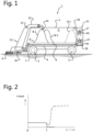
- Fig. 2 diagrammatically shows an exemplary diagram of the rotary speed as a function of time, in arbitrary units.
- the drawn line shows the freewheeling mode in which a constant and low rotary speed is maintained for the removing member(s).
- the control unit can then choose to bring the removing members to a standstill, indicated as an option by the dashed line with a rotary speed zero after instant T. This may be useful, for example, if the animal feed does not yet have to be removed, but filling the feed-processing system has to be stopped, for example.
- Another option is shown by means of a dash-dotted line, and indicates that the control unit moves the removing device correctly to a removing mode, in which the rotary speed is greatly increased.
- other control units or settings are also possible.
- Fig. 3 diagrammatically shows a side view of an alternative feed-processing system 20 according to the invention.
- similar parts are denoted by the same reference numerals, except for one or more accents.
- the system 20 comprises a container 2' with a supply device 21 for supplying a block of animal feed 22 on a conveyor belt 6'.
- Reference numeral 17' denotes a removing device, reference numeral 19' a control unit and reference numeral 23 a feed-collecting trolley.
- the system 20 is a system which is securely fixed with respect to the outside world, but in this case the conveyor belt 6' ensures that the animal feed 22 is moved, which in this case is a block or bale of animal feed. Obviously, it is also possible to move animal feed which is in a different shape and which is first transferred to the belt by means of the supply device 21.
- the container 2' is illustrated as a slanting box in order to make it possible to empty it out into the trolley 23 (by positioning the latter underneath), but could also be designed as a horizontal container, in which for example use may be made of a difference in height between the container 2' and the location or floor for the trolley 23.
- the control unit 19' controls the drive (not shown) of the conveyor belt 6' and allows the removing device 17' to rotate in a freewheeling position during transport.
- the control unit measures an operating parameter of the drive of the removing device 17' by means of a suitable sensor, such as a motor current or rotary speed. If the value of the operating parameter changes to a sufficient degree, the control unit 19' will decide contact between the supplied animal feed 22 and the removing device 17' has taken place, after which, for example, the belt 6' is stopped or the removing device is set to a removing mode, with higher power consumption and/or rotary speed. In the latter case, the system 20 may dispense, for example, removed/separated animal feed to the feed-collecting trolley 23 which may take the collected released animal feed further to a desired location, such as a feed fence.
- Fig. 4 diagrammatically shows a side view of yet another alternative feed-processing system according to the invention, in the form of vehicle 1".
- vehicle 1 is provided with a container 2" and driven wheels 5", as well as a removing member 16" and a removal drive 17", and a control unit 19".
- Reference numeral 30 denotes a pit containing silage.
- vehicle 1" is autonomously self-propelled, although it could also be designed as a trailer behind a tractor or the like, or as a vehicle driven by a driver.
- the vehicle 1" drives autonomously to the pit 30, under the control of the control unit 19".
- the control unit 19" allows the drive 17" to rotate the removing member 16" in a freewheeling mode, at low power and/or rotary speed.
- an operating parameter of the drive 17" is measured. If the latter changes to a sufficient degree, the control unit 19" decides that "contact” has taken place and knows that the vehicle 1", at least the removing member 16", is in operative contact with the pit 30.
- the control unit 19" can then put the removal drive 17" in a removing mode, so that the removing member 16" can remove a part of the pit 30 at higher power and/or rotary speed and tip it into the container 2". Thereafter, the control unit 19" can send the trolley 1" to another destination.
Landscapes
- Life Sciences & Earth Sciences (AREA)
- Environmental Sciences (AREA)
- Birds (AREA)
- Animal Husbandry (AREA)
- Biodiversity & Conservation Biology (AREA)
- Feeding And Watering For Cattle Raising And Animal Husbandry (AREA)
Claims (15)
- Futterverarbeitungssystem (1; 20; 1") zur Verarbeitung von Tierfutter, das Folgendes umfasst:- eine Futterlagervorrichtung (2; 2'; 30) zur Lagerung eines Haufens (8-1, 8-2, 8-n) Tierfutter,- eine Entnahmevorrichtung (15; 17'), z. B. eine Zersetzungs- oder Entladewalze, zum Abgeben einer Futtermenge aus dem Haufen Tierfutter in der Futterlagervorrichtung und mit einem drehbaren Entnahmeelement (16; 16") und einem ersten Antrieb (17; 17") für das Entnahmeelement,- eine Verschiebevorrichtung (6; 6'; 5") mit einem zweiten Antrieb (7), die dazu ausgelegt ist, die Entnahmevorrichtung und den Haufen Tierfutter aufeinander zu zu bewegen,- einen Sensor zum Erfassen eines Sensorsignals, das eine relative Position des Entnahmeelements der Entnahmevorrichtung in Bezug auf den Haufen Tierfutter anzeigt, und- eine Steuereinheit (19; 19'; 19"), die dazu ausgelegt ist, das Futterverarbeitungssystem, insbesondere die Entnahmevorrichtung und die Verschiebevorrichtung, zu steuern,wobei die Steuereinheit dazu ausgelegt ist, basierend auf dem Sensorsignal zu detektieren, ob das Entnahmeelement und der Haufen Tierfutter in Kontakt sind,dadurch gekennzeichnet, dass die Steuereinheit dazu ausgelegt ist, den ersten Antrieb zu veranlassen, das Entnahmeelement während mindestens eines Teils der Bewegung der Entnahmevorrichtung und des Haufens Tierfutter in einem Freilaufmodus aufeinander zu zu treiben, wobei sich das Entnahmeelement nicht in einem Wirkkontakt mit dem Haufen Tierfutter befindet,wobei der Sensor ein Sensorsignal in Bezug auf einen Betriebsparameter des ersten Antriebs misst, undwobei die Steuereinheit dazu ausgelegt ist, das Futterverarbeitungssystem teilweise basierend darauf zu steuern, ob ein Kontakt detektiert wurde oder nicht.
- Futterverarbeitungssystem nach Anspruch 1, wobei die Steuereinheit dazu ausgelegt ist, einen Kontakt zu detektieren, wenn der Betriebsparameter einen vorbestimmten Kontaktschwellenwert erreicht oder überschreitet.
- Futterverarbeitungssystem nach einem der vorhergehenden Ansprüche, wobei der erste Antrieb einen Elektromotor oder einen hydraulischen Antrieb umfasst.
- Futterverarbeitungssystem nach einem der vorhergehenden Ansprüche, wobei der Betriebsparameter einen verbrauchten Strom oder eine verbrauchte Leistung, eine Drehzahl (n) oder ein erzeugtes Drehmoment umfasst.
- Futterverarbeitungssystem nach einem der vorhergehenden Ansprüche, wobei die Steuerung des Futterverarbeitungssystems die Steuerung, insbesondere das Anhalten, des zweiten Antriebs umfasst, wenn die Steuereinheit den Kontakt detektiert.
- Futterverarbeitungssystem nach einem der vorhergehenden Ansprüche, wobei die Steuerung des Futterverarbeitungssystems umfasst, den ersten Antrieb zu veranlassen, das Entnahmeelement in einem Entnahmemodus anzutreiben, wenn die Steuereinheit den Kontakt detektiert hat, wobei das Entnahmeelement Tierfutter freigibt und aus dem Haufen Tierfutter entnimmt, und wobei der erste Antrieb mit einer höheren Drehzahl und/oder Leistung als im Freilaufmodus arbeitet.
- Futterverarbeitungssystem nach Anspruch 6, wobei die Steuereinheit den ersten Antrieb im Entnahmemodus mittels des Sensorsignals bzw. eines anderen Sensorsignals bezüglich des Betriebsparameters bzw. eines anderen Betriebsparameters steuert.
- Futterverarbeitungssystem nach einem der vorhergehenden Ansprüche, wobei die Futterlagerungsvorrichtung einen Lagerboden, insbesondere in einer Halterung, in einer festen Position zur Außenwelt umfasst.
- Futterverarbeitungssystem nach Anspruch 8, wobei die Entnahmevorrichtung (17') fest angeordnet ist und die Verschiebevorrichtung dazu ausgebildet ist, den Haufen Tierfutter (22) in der Futterlagerungsvorrichtung zur Entnahmevorrichtung hin zu bewegen, und insbesondere einen beweglichen Ladeboden (6') oder eine Bodenkette umfasst.
- Futterverarbeitungssystem nach Anspruch 8, wobei die Entnahmevorrichtung ein verschiebbares Fahrzeug (1") umfasst, das das Entnahmeelement (16") trägt.
- Futterverarbeitungssystem nach einem der vorhergehenden Ansprüche, wobei das Futterverarbeitungssystem ein Fahrzeug (1; 1") umfasst, an dem sowohl die Futterlagerungsvorrichtung (2; 2") als auch die Entnahmevorrichtung (16; 16") bereitgestellt sind.
- Futterverarbeitungssystem nach Anspruch 10 oder 11, wobei das Fahrzeug autonom selbstfahrend ist.
- Futterverarbeitungssystem nach einem der Ansprüche 10, 11 oder 12, ferner umfassend eine Schneidvorrichtung (10) zum Schneiden von Pflanzen (9) auf dem Feld und eine Sammeleinrichtung (11, 12, 13) zum Sammeln der geschnittenen Pflanzen und zum Weiterleiten an die Futterlagerungsvorrichtung.
- Futterverarbeitungssystem nach Anspruch 13, ferner umfassend eine Dosiereinrichtung (18) zum Ausdosieren des Futters und/oder der Schnittpflanzen an Tiere.
- Futterverarbeitungssystem nach Anspruch 14, wobei die Entnahmevorrichtung (15) als Dosiervorrichtung dient.
Applications Claiming Priority (2)
| Application Number | Priority Date | Filing Date | Title |
|---|---|---|---|
| NL2023391A NL2023391B1 (nl) | 2019-06-26 | 2019-06-26 | Diervoerverwerkingssysteem |
| PCT/NL2020/050394 WO2020263080A1 (en) | 2019-06-26 | 2020-06-19 | Feed-processing system |
Publications (3)
| Publication Number | Publication Date |
|---|---|
| EP3989708A1 EP3989708A1 (de) | 2022-05-04 |
| EP3989708C0 EP3989708C0 (de) | 2025-03-05 |
| EP3989708B1 true EP3989708B1 (de) | 2025-03-05 |
Family
ID=67352561
Family Applications (1)
| Application Number | Title | Priority Date | Filing Date |
|---|---|---|---|
| EP20745328.3A Active EP3989708B1 (de) | 2019-06-26 | 2020-06-19 | Futterverarbeitungssystem |
Country Status (5)
| Country | Link |
|---|---|
| US (1) | US12279598B2 (de) |
| EP (1) | EP3989708B1 (de) |
| CA (1) | CA3141702A1 (de) |
| NL (1) | NL2023391B1 (de) |
| WO (1) | WO2020263080A1 (de) |
Families Citing this family (2)
| Publication number | Priority date | Publication date | Assignee | Title |
|---|---|---|---|---|
| NL2023390B1 (en) * | 2019-06-26 | 2021-02-01 | Lely Patent Nv | Method of feeding a group of animals at a feeding location and system for performing the method |
| US20240122158A1 (en) * | 2022-10-17 | 2024-04-18 | Meyers Manufacturing Corporation | Feed-Delivery Container for Automated Dairy Feeding System |
Family Cites Families (31)
| Publication number | Priority date | Publication date | Assignee | Title |
|---|---|---|---|---|
| GB905116A (en) * | 1959-12-05 | 1962-09-05 | Harrison Mcgregor & Guest Ltd | New or improved agricultural machine |
| FR2618047B1 (fr) * | 1987-07-15 | 1990-06-15 | Ariat | Machine agricole polyvalente utilisable comme desileuse, distributrice, derouleuse, pailleuse, melangeuse et recolteuse-chargeuse |
| US4981107A (en) * | 1989-03-31 | 1991-01-01 | Micro-Contact Inc. | Computerized automatic cattle-feeder system |
| DE4006236A1 (de) * | 1990-02-28 | 1991-08-29 | Alois Assfalg | Vorrichtung zum abtragen von wenigstens unter lagerdruck zusammengepresstem foerdergut aus einem futterstock, silo oder presskoerper |
| NL9400297A (nl) * | 1994-02-28 | 1995-10-02 | Trioliet Mullos | Inrichting en werkwijze voor het doseren van silagemateriaal. |
| NL9401876A (nl) * | 1994-11-10 | 1996-06-03 | Maasland Nv | Voerwagen. |
| DE19612053A1 (de) * | 1996-03-27 | 1997-10-02 | Erwin Schluetter | Vorrichtung zum Ernten von Häckselgütern, insbesondere Mais oder Gras |
| US5813616A (en) * | 1996-11-29 | 1998-09-29 | Fastec Manufacturing | Bale processor |
| US6572039B1 (en) * | 1999-09-03 | 2003-06-03 | David G. Kruer | Variable mulch handling and dispersing apparatus |
| CA2291319C (en) * | 1999-11-30 | 2008-02-19 | Bridgeview Mfg. Inc. | Square bale processor |
| FR2802767B1 (fr) * | 1999-12-24 | 2002-10-31 | Lucas Sa G | Dispositif de demelage-dechiquetage pour tous types de fourrage et produits conditionnes en balles |
| US20100219275A1 (en) * | 2004-10-14 | 2010-09-02 | Weiss Leonard D | Bale processing apparatus |
| US20070290087A1 (en) * | 2004-10-14 | 2007-12-20 | Weiss Leonard D | Bale processor |
| DE102007018321A1 (de) * | 2007-04-18 | 2008-10-23 | Alois Pöttinger Maschinenfabrik Gmbh | Erntemaschine |
| DE102008002006A1 (de) * | 2008-05-27 | 2009-12-03 | Deere & Company, Moline | Steueranordnung zur Kontrolle des Überladens landwirtschaftlichen Ernteguts von einer Erntemaschine auf ein Transportfahrzeug |
| DE102009027245A1 (de) * | 2009-06-26 | 2010-12-30 | Deere & Company, Moline | Steueranordnung zur Kontrolle des Überladens landwirtschaftlichen Ernteguts von einer Erntemaschine auf ein Transportfahrzeug |
| DE102009042243A1 (de) * | 2009-09-18 | 2011-03-31 | B. Strautmann & Söhne GmbH u. Co | Fräsvorrichtung an einem Futtermischwagen |
| DE102010038661B4 (de) * | 2010-07-29 | 2020-07-02 | Deere & Company | Erntemaschine mit einem an einem Fluggerät befestigten Sensor |
| US9861040B2 (en) * | 2012-02-10 | 2018-01-09 | Deere & Company | Method and stereo vision system for facilitating the unloading of agricultural material from a vehicle |
| DE102012112154A1 (de) * | 2012-12-12 | 2014-06-12 | Usines Claas France S.A.S. | Landwirtschaftliche Erntemaschine und Verfahren zum Warten einer solchen Erntemaschine |
| US9648797B2 (en) * | 2013-07-19 | 2017-05-16 | Trebro Holding, Inc. | Sod harvester with flap control device |
| DE102013107757B4 (de) * | 2013-07-19 | 2015-12-24 | Claas Saulgau Gmbh | Verfahren zum Betreiben eines landwirtschaftlichen Ladewagens und Steuerungseinrichtung |
| US10499614B2 (en) | 2014-04-03 | 2019-12-10 | Delaval Holding Ab | Animal forage handling arrangement and method of controlling the same |
| US10492464B2 (en) * | 2014-07-15 | 2019-12-03 | Lely Patent N.V. | Livestock farming system |
| DE102014116882B4 (de) * | 2014-11-18 | 2018-05-24 | B. Strautmann & Söhne GmbH u. Co. KG | Verfahren zur Entnahme von Futtermitteln aus Fahrsilos |
| US9826683B2 (en) * | 2015-11-04 | 2017-11-28 | Deere & Company | Grain mass flow rate determination |
| DE102017113241B4 (de) * | 2017-06-16 | 2022-01-05 | Fliegl Agrartechnik Gmbh | Überladevorrichtung zum Aufsammeln und Übergeben von Erntegut an einen Transportwagen |
| FR3068861B1 (fr) * | 2017-07-13 | 2019-10-11 | Kuhn-Audureau Sa | Vehicule automoteur pour collecter et distribuer des produits fragmentaires |
| US10412888B2 (en) * | 2017-08-21 | 2019-09-17 | Cnh Industrial America Llc | System and method for controlling elevator speeds for an agricultural harvester during operation within a storage harvesting mode |
| US10736271B2 (en) * | 2017-11-01 | 2020-08-11 | Deere & Company | Automatic product fill method and control system |
| US11310963B2 (en) * | 2019-10-31 | 2022-04-26 | Deere & Company | Automated fill strategy for grain cart using open-loop volumetric estimation of fill level |
-
2019
- 2019-06-26 NL NL2023391A patent/NL2023391B1/nl not_active IP Right Cessation
-
2020
- 2020-06-19 US US17/615,929 patent/US12279598B2/en active Active
- 2020-06-19 EP EP20745328.3A patent/EP3989708B1/de active Active
- 2020-06-19 CA CA3141702A patent/CA3141702A1/en active Pending
- 2020-06-19 WO PCT/NL2020/050394 patent/WO2020263080A1/en not_active Ceased
Also Published As
| Publication number | Publication date |
|---|---|
| CA3141702A1 (en) | 2020-12-30 |
| US20220312726A1 (en) | 2022-10-06 |
| US12279598B2 (en) | 2025-04-22 |
| NL2023391B1 (nl) | 2021-02-01 |
| EP3989708C0 (de) | 2025-03-05 |
| WO2020263080A1 (en) | 2020-12-30 |
| EP3989708A1 (de) | 2022-05-04 |
Similar Documents
| Publication | Publication Date | Title |
|---|---|---|
| EP2838356B1 (de) | Vorrichtung zur futterverteilung | |
| DK2892326T3 (en) | System and method for conducting an animal related story | |
| US20250359510A1 (en) | Automated grain filling system and related methods | |
| EP3989708B1 (de) | Futterverarbeitungssystem | |
| US11904566B1 (en) | Pine straw baling apparatus and method | |
| EP2232982B1 (de) | Vorrichtung und Verfahren zum Schneiden von Silage | |
| CN112955006A (zh) | 饲养系统以及用于饲养动物的方法 | |
| RU2756560C2 (ru) | Перегрузочное устройство для сбора и передачи убранного материала на транспортное средство | |
| EP1547457B1 (de) | Zusammensetzung und Düngerstreumaschine zum Durchführen einer Verteilung von Dünger | |
| CN113923978B (zh) | 用于刈割植物、尤其是草的系统以及通过此系统来喂养动物的方法 | |
| EP2398314A1 (de) | Anlage zum füttern von vieh | |
| EP4075959B1 (de) | Fütterungssystem und verfahren zur fütterung von tieren | |
| EP2710890B1 (de) | Verteilungssystem von Trockenfutter, konzentriertem Futter und/oder Streu für Vieh, bei dem ein selbst gesteuertes Fahrzeug zum Einsatz kommt | |
| EP4075956B1 (de) | Behältervorrichtung für tierfutter, füttersystem, ladewagen und automatische ernte-, transport- und futterdosiervorrichtung mit der behältervorrichtung | |
| US20250017171A1 (en) | Driving robot for agricultural tasks | |
| PL244390B1 (pl) | Sposób sterowania urządzeniem do pobierania paszy | |
| FR2995758A1 (fr) | Systeme de distribution de fourrage, de concentre et/ou de litiere a du betail mettant en oeuvre un vehicule autoguide |
Legal Events
| Date | Code | Title | Description |
|---|---|---|---|
| STAA | Information on the status of an ep patent application or granted ep patent |
Free format text: STATUS: UNKNOWN |
|
| STAA | Information on the status of an ep patent application or granted ep patent |
Free format text: STATUS: THE INTERNATIONAL PUBLICATION HAS BEEN MADE |
|
| PUAI | Public reference made under article 153(3) epc to a published international application that has entered the european phase |
Free format text: ORIGINAL CODE: 0009012 |
|
| STAA | Information on the status of an ep patent application or granted ep patent |
Free format text: STATUS: REQUEST FOR EXAMINATION WAS MADE |
|
| 17P | Request for examination filed |
Effective date: 20220126 |
|
| AK | Designated contracting states |
Kind code of ref document: A1 Designated state(s): AL AT BE BG CH CY CZ DE DK EE ES FI FR GB GR HR HU IE IS IT LI LT LU LV MC MK MT NL NO PL PT RO RS SE SI SK SM TR |
|
| DAV | Request for validation of the european patent (deleted) | ||
| DAX | Request for extension of the european patent (deleted) | ||
| GRAP | Despatch of communication of intention to grant a patent |
Free format text: ORIGINAL CODE: EPIDOSNIGR1 |
|
| STAA | Information on the status of an ep patent application or granted ep patent |
Free format text: STATUS: GRANT OF PATENT IS INTENDED |
|
| RIC1 | Information provided on ipc code assigned before grant |
Ipc: A01F 29/00 20060101ALN20241014BHEP Ipc: A01D 90/10 20060101ALN20241014BHEP Ipc: A01D 90/04 20060101ALN20241014BHEP Ipc: A01K 5/02 20060101ALI20241014BHEP Ipc: A01F 25/20 20060101AFI20241014BHEP |
|
| INTG | Intention to grant announced |
Effective date: 20241024 |
|
| GRAS | Grant fee paid |
Free format text: ORIGINAL CODE: EPIDOSNIGR3 |
|
| GRAA | (expected) grant |
Free format text: ORIGINAL CODE: 0009210 |
|
| STAA | Information on the status of an ep patent application or granted ep patent |
Free format text: STATUS: THE PATENT HAS BEEN GRANTED |
|
| AK | Designated contracting states |
Kind code of ref document: B1 Designated state(s): AL AT BE BG CH CY CZ DE DK EE ES FI FR GB GR HR HU IE IS IT LI LT LU LV MC MK MT NL NO PL PT RO RS SE SI SK SM TR |
|
| REG | Reference to a national code |
Ref country code: GB Ref legal event code: FG4D |
|
| REG | Reference to a national code |
Ref country code: CH Ref legal event code: EP |
|
| REG | Reference to a national code |
Ref country code: IE Ref legal event code: FG4D |
|
| REG | Reference to a national code |
Ref country code: DE Ref legal event code: R096 Ref document number: 602020047228 Country of ref document: DE |
|
| U01 | Request for unitary effect filed |
Effective date: 20250310 |
|
| U07 | Unitary effect registered |
Designated state(s): AT BE BG DE DK EE FI FR IT LT LU LV MT NL PT RO SE SI Effective date: 20250317 |
|
| PG25 | Lapsed in a contracting state [announced via postgrant information from national office to epo] |
Ref country code: RS Free format text: LAPSE BECAUSE OF FAILURE TO SUBMIT A TRANSLATION OF THE DESCRIPTION OR TO PAY THE FEE WITHIN THE PRESCRIBED TIME-LIMIT Effective date: 20250605 |
|
| PG25 | Lapsed in a contracting state [announced via postgrant information from national office to epo] |
Ref country code: ES Free format text: LAPSE BECAUSE OF FAILURE TO SUBMIT A TRANSLATION OF THE DESCRIPTION OR TO PAY THE FEE WITHIN THE PRESCRIBED TIME-LIMIT Effective date: 20250305 |
|
| PGFP | Annual fee paid to national office [announced via postgrant information from national office to epo] |
Ref country code: GB Payment date: 20250627 Year of fee payment: 6 |
|
| PG25 | Lapsed in a contracting state [announced via postgrant information from national office to epo] |
Ref country code: NO Free format text: LAPSE BECAUSE OF FAILURE TO SUBMIT A TRANSLATION OF THE DESCRIPTION OR TO PAY THE FEE WITHIN THE PRESCRIBED TIME-LIMIT Effective date: 20250605 |
|
| PG25 | Lapsed in a contracting state [announced via postgrant information from national office to epo] |
Ref country code: HR Free format text: LAPSE BECAUSE OF FAILURE TO SUBMIT A TRANSLATION OF THE DESCRIPTION OR TO PAY THE FEE WITHIN THE PRESCRIBED TIME-LIMIT Effective date: 20250305 |
|
| PG25 | Lapsed in a contracting state [announced via postgrant information from national office to epo] |
Ref country code: GR Free format text: LAPSE BECAUSE OF FAILURE TO SUBMIT A TRANSLATION OF THE DESCRIPTION OR TO PAY THE FEE WITHIN THE PRESCRIBED TIME-LIMIT Effective date: 20250606 |
|
| U20 | Renewal fee for the european patent with unitary effect paid |
Year of fee payment: 6 Effective date: 20250630 |
|
| PG25 | Lapsed in a contracting state [announced via postgrant information from national office to epo] |
Ref country code: SM Free format text: LAPSE BECAUSE OF FAILURE TO SUBMIT A TRANSLATION OF THE DESCRIPTION OR TO PAY THE FEE WITHIN THE PRESCRIBED TIME-LIMIT Effective date: 20250305 |
|
| PG25 | Lapsed in a contracting state [announced via postgrant information from national office to epo] |
Ref country code: PL Free format text: LAPSE BECAUSE OF FAILURE TO SUBMIT A TRANSLATION OF THE DESCRIPTION OR TO PAY THE FEE WITHIN THE PRESCRIBED TIME-LIMIT Effective date: 20250305 |
|
| PG25 | Lapsed in a contracting state [announced via postgrant information from national office to epo] |
Ref country code: CZ Free format text: LAPSE BECAUSE OF FAILURE TO SUBMIT A TRANSLATION OF THE DESCRIPTION OR TO PAY THE FEE WITHIN THE PRESCRIBED TIME-LIMIT Effective date: 20250305 |
|
| PG25 | Lapsed in a contracting state [announced via postgrant information from national office to epo] |
Ref country code: SK Free format text: LAPSE BECAUSE OF FAILURE TO SUBMIT A TRANSLATION OF THE DESCRIPTION OR TO PAY THE FEE WITHIN THE PRESCRIBED TIME-LIMIT Effective date: 20250305 |
|
| PG25 | Lapsed in a contracting state [announced via postgrant information from national office to epo] |
Ref country code: IS Free format text: LAPSE BECAUSE OF FAILURE TO SUBMIT A TRANSLATION OF THE DESCRIPTION OR TO PAY THE FEE WITHIN THE PRESCRIBED TIME-LIMIT Effective date: 20250705 |
|
| PLBE | No opposition filed within time limit |
Free format text: ORIGINAL CODE: 0009261 |
|
| STAA | Information on the status of an ep patent application or granted ep patent |
Free format text: STATUS: NO OPPOSITION FILED WITHIN TIME LIMIT |
|
| REG | Reference to a national code |
Ref country code: CH Ref legal event code: L10 Free format text: ST27 STATUS EVENT CODE: U-0-0-L10-L00 (AS PROVIDED BY THE NATIONAL OFFICE) Effective date: 20260114 |
|
| REG | Reference to a national code |
Ref country code: CH Ref legal event code: H13 Free format text: ST27 STATUS EVENT CODE: U-0-0-H10-H13 (AS PROVIDED BY THE NATIONAL OFFICE) Effective date: 20260127 |
|
| PG25 | Lapsed in a contracting state [announced via postgrant information from national office to epo] |
Ref country code: MC Free format text: LAPSE BECAUSE OF FAILURE TO SUBMIT A TRANSLATION OF THE DESCRIPTION OR TO PAY THE FEE WITHIN THE PRESCRIBED TIME-LIMIT Effective date: 20250305 |