EP3987754B1 - Am helm montierte funkanordnung mit erweiterten steuerungen - Google Patents
Am helm montierte funkanordnung mit erweiterten steuerungen Download PDFInfo
- Publication number
- EP3987754B1 EP3987754B1 EP19935610.6A EP19935610A EP3987754B1 EP 3987754 B1 EP3987754 B1 EP 3987754B1 EP 19935610 A EP19935610 A EP 19935610A EP 3987754 B1 EP3987754 B1 EP 3987754B1
- Authority
- EP
- European Patent Office
- Prior art keywords
- helmet
- radio device
- microchip
- radio
- way radio
- Prior art date
- Legal status (The legal status is an assumption and is not a legal conclusion. Google has not performed a legal analysis and makes no representation as to the accuracy of the status listed.)
- Active
Links
Images

Classifications
-
- H—ELECTRICITY
- H04—ELECTRIC COMMUNICATION TECHNIQUE
- H04R—LOUDSPEAKERS, MICROPHONES, GRAMOPHONE PICK-UPS OR LIKE ACOUSTIC ELECTROMECHANICAL TRANSDUCERS; ELECTRIC HEARING AIDS; PUBLIC ADDRESS SYSTEMS
- H04R1/00—Details of transducers, loudspeakers or microphones
- H04R1/10—Earpieces; Attachments therefor ; Earphones; Monophonic headphones
- H04R1/1041—Mechanical or electronic switches, or control elements
-
- A—HUMAN NECESSITIES
- A42—HEADWEAR
- A42B—HATS; HEAD COVERINGS
- A42B3/00—Helmets; Helmet covers ; Other protective head coverings
- A42B3/04—Parts, details or accessories of helmets
- A42B3/30—Mounting radio sets or communication systems
-
- H—ELECTRICITY
- H04—ELECTRIC COMMUNICATION TECHNIQUE
- H04B—TRANSMISSION
- H04B1/00—Details of transmission systems, not covered by a single one of groups H04B3/00 - H04B13/00; Details of transmission systems not characterised by the medium used for transmission
- H04B1/38—Transceivers, i.e. devices in which transmitter and receiver form a structural unit and in which at least one part is used for functions of transmitting and receiving
- H04B1/3827—Portable transceivers
- H04B1/385—Transceivers carried on the body, e.g. in helmets
- H04B2001/3866—Transceivers carried on the body, e.g. in helmets carried on the head
-
- H—ELECTRICITY
- H04—ELECTRIC COMMUNICATION TECHNIQUE
- H04R—LOUDSPEAKERS, MICROPHONES, GRAMOPHONE PICK-UPS OR LIKE ACOUSTIC ELECTROMECHANICAL TRANSDUCERS; ELECTRIC HEARING AIDS; PUBLIC ADDRESS SYSTEMS
- H04R1/00—Details of transducers, loudspeakers or microphones
- H04R1/10—Earpieces; Attachments therefor ; Earphones; Monophonic headphones
- H04R1/1016—Earpieces of the intra-aural type
-
- H—ELECTRICITY
- H04—ELECTRIC COMMUNICATION TECHNIQUE
- H04R—LOUDSPEAKERS, MICROPHONES, GRAMOPHONE PICK-UPS OR LIKE ACOUSTIC ELECTROMECHANICAL TRANSDUCERS; ELECTRIC HEARING AIDS; PUBLIC ADDRESS SYSTEMS
- H04R1/00—Details of transducers, loudspeakers or microphones
- H04R1/10—Earpieces; Attachments therefor ; Earphones; Monophonic headphones
- H04R1/1058—Manufacture or assembly
- H04R1/1066—Constructional aspects of the interconnection between earpiece and earpiece support
-
- H—ELECTRICITY
- H04—ELECTRIC COMMUNICATION TECHNIQUE
- H04R—LOUDSPEAKERS, MICROPHONES, GRAMOPHONE PICK-UPS OR LIKE ACOUSTIC ELECTROMECHANICAL TRANSDUCERS; ELECTRIC HEARING AIDS; PUBLIC ADDRESS SYSTEMS
- H04R2430/00—Signal processing covered by H04R, not provided for in its groups
- H04R2430/01—Aspects of volume control, not necessarily automatic, in sound systems
Definitions
- the present disclosure generally relates to a two-way radio device for communication, and more particularly to a two-way radio device adapted to be removably mounted to a helmet and having extended controls for convenient use of a user.
- WO 2002087282A1 discloses a communications system attached to a helmet using a resilient clip adapted to use spring forces to elastically and removably grasp the lower peripheral rim of the helmet. Rigidly fixed to the resilient clip is a junction box. A microphone and speakers are attached to the helmet and are electrically connected to a transceiver through the junction box.
- US 4,607,395 also discloses a helmet with a two-way radio, having an easily accessible rotatable volume control knob.
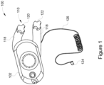
- FIG. 1 illustrates a diagrammatic view of a radio device 100 , in accordance with one or more embodiments of the present disclosure.
- the radio device 100 may be any short range wireless communication device which can be used for simple yet effective communication between people, such as co-workers in a worksite.
- the radio device 100 has the advantage that it is not reliant on transmission towers to be in the area, and thus can be used as a reliable means for communication in remote and difficult work environments, such as a mining facility, construction site, etc.
- the radio device 100 is generally in the form of a "control box" with means for controlling communication, and the two terms have been interchangeably used hereinafter without any limitations.
- the radio device 100 includes a body 102 to house various components therein, such as conventional speaker elements (not illustrated) and circuitry.
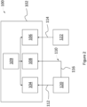
- Figure 2 illustrates a schematic block diagram of the radio device 100 of the present disclosure.
- the radio device 100 includes multiple circuits to control various functions thereof.
- the radio device 100 includes a volume microchip 104 configured to control output volume of the radio device 100 , as per instructions from the user.
- the radio device 100 also includes a channel microchip 106 configured to select the connecting channel frequency of the radio device 100 , as per instructions from the user.
- the radio device 100 includes an on/off microchip 108 configured to switch ON and OFF the radio device 100 , as per instructions from the user.
- the volume microchip 104 , the channel microchip 106 and the on/off microchip 108 are generally located inside the body 102 of the radio device 100.
- the radio device 100 may further include a battery 109 for powering the various components thereof.
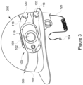
- Figure 3 shows pushbutton 119 known in the art to turn on a microphone. Pushbutton 119 is pressed prior to a user speaking into headphone/microphone combination 124 or a stand alone microphone.
- the radio device 100 includes extended controls 110 for controlling various functions thereof, in accordance with one or more embodiments of the present disclosure.
- the said extended controls 110 are located outside of the body 102 of the radio device 100.
- the radio device 100 includes at least one extension member.
- the radio device 100 includes multiple extension members, namely a first extension 112 electrically connected to the volume microchip 104 and the second extension 114 electrically connected to the channel microchip 106.
- the radio device 100 may include a third extension 116 which may be connected to the on/off microchip 108.
- the extensions 112 , 114 and 116 include signal conducting wires extending from inside of the body 102 of the radio device 100.
- these extensions 112 , 114 and 116 are respectively connected to the volume microchip 104 , the channel microchip 106 and the on/off microchip 108 inside the body 102.
- the extensions 112 , 114 and 116 may be in the form of computer bus cables which are adapted to be utilized for transferring data as well as voltage signals.
- the extensions 112, 114 and 116 are covered in sheath layers 118 in order to be protected from physical damage as well as electronic interference.
- the third extension 116 may be paired with either one of the first extension 112 or the second extension 114 inside the corresponding sheath layer 118. In the illustrated example of Figure 2 , the third extension 116 has been shown to be paired with the first extension 11 2 , in the radio device 100.
- the extended controls 110 include controls connected to the distal end of the extensions for sending instructions to the correspondingly connected microchip therewith.
- the first extension 112 has a volume dial 120 electrically connected at the distal end thereof
- the second extension 114 has a channel dial 122 electrically connected at the distal end thereof.
- the third extension 116 may also be electrically connected to the volume dial 120 at the distal end thereof.
- the volume dial 120 connected to the volume microchip 104 , can be used to regulate the output volume of the radio device 100. That is, a user by turning the volume dial 120 in one direction, say clockwise direction, can increase the output volume of the radio device 100 ; and by turning the volume dial 120 in opposite direction, i.e.
- the channel dial 122 connected to the channel microchip 106 , can be used to regulate the connecting channel frequency of the radio device 100. That is, a user by turning the channel dial 122 in one direction, say clockwise direction, can increase the connecting channel frequency of the radio device 100 ; and by turning the channel dial 122 in opposite direction, i.e. the anti-clockwise direction, can decrease the connecting channel frequency of the radio device 100.
- the volume dial 120 may also be used for switching ON and OFF the radio device 100.
- the volume dial 120 when the volume dial 120 is turned all the way back in one direction, say the anti-clockwise direction, to its initial position, the volume dial 120 sends a signal to the on/off microchip 108 via the third extension 116 to switch OFF the radio device 100 ; and when the volume dial 120 is turned a bit in opposite direction, i.e. the clockwise direction, the volume dial 120 sends a signal to the on/off microchip 108 via the third extension 116 to switch ON the radio device 100.
- the third extension 116 may be connected to the channel dial 122 ; and, in such case, the channel dial 122 may be utilized for the purpose of switching ON and OFF the radio device 100.
- the radio device 100 may optionally be connected with a headphone/microphone 124 for listening to the communication from the radio device 100.
- the headphone/microphone 124 is extending outwardly of the body 102 by means of a wire 126.
- the wire 126 has been shown to be a coiled wire; however, in other examples, the wire 126 may be a non-coiled wire without any limitations.
- the headphone/microphone 124 may be inserted by the user in his/her ear to listen to the communication from the radio device 100.
- the helmet-mounted radio assembly 200 includes a helmet 202 to which the radio device 100 is mounted.
- the helmet-mounted radio assembly 200 includes mounting members.
- the helmet-mounted radio assembly 200 includes a mounting arrangement 300 having a band 302 wrapped around and supported on the outer surface of the helmet 202.
- the mounting arrangement 300 includes a clip 304 attached to a back side of the body 102 of the radio device 100.
- the clip 304 can be used to engage with the band 302 for mounting the radio device 100 to the helmet 202, in the helmet-mounted radio assembly 200.
- the helmet-mounted radio assembly 200 may utilize a mounting arrangement 400 using screws 402 as mounting member for mounting the radio device 100 to the helmet 202.
- the helmet-mounted radio assembly 200 may include a carriage (not shown) fixed or adhered to the helmet 202 , and the carriage in turn may support the radio device 100 therein.
- the helmet-mounted radio assembly 200 may include one or more solar panels (not shown) fixed to the outer surface of the helmet 200 to generate electric power and electrically connected to the battery 109 of the radio device 100. The generated power could charge the battery 109 to in turn be used for powering the radio device 100.
- Conventional radio device includes volume controls and channel controls provided on the body thereof.
- Such controls are, typically, in the form of small buttons or dials which may not be easily accessible by a user wearing gloves or the like, especially when the radio device is mounted on a helmet and not in direct sight of the user. Thus, the user may have to fiddle around to find the right button or dial which is cumbersome.
- the extended controls 110 in the radio device 100 of the present disclosure the user can easily locate the right control dials for controlling the desired function of the radio device 100.
- the sheath layers 118 provides waterproof and dustproof arrangement for the extended controls 110.
- the radio device 100 may be arranged in any manner in the helmet-mounted radio assembly 200 in order for the dials 120 and 122 to be within easy approach of the user.
- the radio device 100 may be oriented such that the extended controls 110 may be hanging in downward direction for the dials 120 and 122 to be in relative proximity to the user.
- the radio device 100 doesn't interfere with work to be performed by the user.
- the radio device 100 may be completely unobtrusive in that it may be positioned inside or on the helmet 202 or other headgear of the user.
- the present invention's industrial applicability includes a helmet-mounted radio assembly with extended controls.
- the helmet-mounted radio assembly further includes a radio device removably mounted on a helmet.
- the present invention utilizes reliable mounting arrangements, such as bands, clips, screws or other suitable means, in order to removably mount the radio device to the helmet.
- the radio device includes extensions for controlling various functions thereof.
- a user can have extended controls ergonomically located within easy reach thereof for controlling the regular functions of the radio device, like volume control, changing channel frequency, or switching the radio device on or off.
Landscapes
- Engineering & Computer Science (AREA)
- Signal Processing (AREA)
- Computer Networks & Wireless Communication (AREA)
- Physics & Mathematics (AREA)
- Acoustics & Sound (AREA)
- Transceivers (AREA)
- Helmets And Other Head Coverings (AREA)
Claims (7)
- Helm (202), Folgendes umfassend:
ein daran montiertes Zwei-Wege-Funkgerät (100) mit einem Umfang, gekennzeichnet durch zwei Verlängerungen (112, 114), die sich von dem Zwei-Wege-Funkgerät (100) weg erstrecken, wobei jede Verlängerung einen Knopf an ihrem distalen Ende aufweist, wobei ein erster Knopf (122) mit einem Kanal-Mikrochip (106) verbunden ist, wobei ein zweiter Knopf (120) mit einem Ein- und Aus-Mikrochip (108) verbunden ist, wobei der zweite Knopf (120) auch mit einem Lautstärke-Mikrochip (104) verbunden ist, eine Batterie (109), die zum Versorgen des ersten, zweiten und dritten Mikrochips (104, 106, 108) verwendet wird; wobei der erste und der zweite Knopf (120, 122) vollständig außerhalb des Umfangs lokalisiert sind. - Helm nach Anspruch 1, wobei das Zwei-Wege-Funkgerät (100) drehbar an einer dritten Verlängerung (116) montiert ist, die ein distales Ende und einen dritten Knopf an dem distalen Ende aufweist, wobei der dritte Knopf mit dem Lautstärke- oder Ein- und Aus-Mikrochip verbunden ist.
- Helm nach Anspruch 1, wobei das Zwei-Wege-Funkgerät (100) Hüllschichten (118) einschließt, die geeignet sind, den Körper vor physischen Schäden und elektronischen Störungen zu schützen.
- Helm nach Anspruch 1, wobei eine Mikrofon- und Kopfhörer-Kombinationseinheit (124) unter Verwendung eines Kabels (126) an dem Zwei-Wege-Funkgerät (100) montiert ist.
- Helm nach Anspruch 1, wobei ein Druckknopf (119) an dem Zwei-Wege-Funkgerät (100) lokalisiert ist und dazu geeignet ist, das Mikrofon einzuschalten.
- Helm nach Anspruch 1, der ein Band (302) aufweist, das sich um den Helm herum erstreckt, wobei das Band (302) dazu verwendet wird, das Zwei-Wege-Funkgerät (100) an dem Helm zu montieren.
- Helm nach Anspruch 1, wobei der Helm ein vorderes Ende und ein hinteres Ende einschließt, wobei die beiden Verlängerungen (112, 114) sich beide in Richtung des hinteren Endes erstrecken.
Applications Claiming Priority (1)
| Application Number | Priority Date | Filing Date | Title |
|---|---|---|---|
| PCT/US2019/038760 WO2020263220A1 (en) | 2019-06-24 | 2019-06-24 | Helmet-mounted radio assembly with extended controls |
Publications (4)
| Publication Number | Publication Date |
|---|---|
| EP3987754A1 EP3987754A1 (de) | 2022-04-27 |
| EP3987754A4 EP3987754A4 (de) | 2023-04-05 |
| EP3987754C0 EP3987754C0 (de) | 2024-07-24 |
| EP3987754B1 true EP3987754B1 (de) | 2024-07-24 |
Family
ID=74062051
Family Applications (1)
| Application Number | Title | Priority Date | Filing Date |
|---|---|---|---|
| EP19935610.6A Active EP3987754B1 (de) | 2019-06-24 | 2019-06-24 | Am helm montierte funkanordnung mit erweiterten steuerungen |
Country Status (3)
| Country | Link |
|---|---|
| EP (1) | EP3987754B1 (de) |
| CN (1) | CN114073062B (de) |
| WO (1) | WO2020263220A1 (de) |
Families Citing this family (1)
| Publication number | Priority date | Publication date | Assignee | Title |
|---|---|---|---|---|
| EP4335036A4 (de) * | 2021-05-05 | 2025-03-26 | 3M Innovative Properties Company | Push-to-talk (ptt)-knopf und nfc-antennenanordnung |
Family Cites Families (10)
| Publication number | Priority date | Publication date | Assignee | Title |
|---|---|---|---|---|
| US4357711A (en) * | 1981-01-29 | 1982-11-02 | Joseph Drefko | Two way radio safety helmet |
| US4607395A (en) * | 1984-02-06 | 1986-08-19 | Bell Helmets Inc. | Helmet radio control package |
| AU4551493A (en) * | 1992-07-27 | 1994-02-14 | George Kevin Trevitt | Safety helmet incorporating interface for radio communications |
| CN101023704A (zh) * | 2004-05-28 | 2007-08-22 | Gn奈康有限公司 | 头戴式耳机和头戴式受话器 |
| US9455677B2 (en) * | 2013-01-10 | 2016-09-27 | Sdi Technologies, Inc. | Wireless audio control apparatus |
| US9042944B2 (en) * | 2013-09-16 | 2015-05-26 | Michael D. Dieringer | Communication system for helmeted user |
| EP3010153A1 (de) * | 2014-10-13 | 2016-04-20 | Cardo International GmbH | Kommunikationssystem für einen Helm |
| GB2553950A (en) * | 2015-05-14 | 2018-03-21 | Peclet Ltd | A module, attachable to a helmet |
| CN206586471U (zh) * | 2017-03-14 | 2017-10-27 | 深圳利丰宝运动用品有限公司 | 具有收音功能的头盔 |
| CN107432523A (zh) * | 2017-09-21 | 2017-12-05 | 中晨科技(深圳)有限公司 | 多功能头盔对讲机及系统和使用方法 |
-
2019
- 2019-06-24 WO PCT/US2019/038760 patent/WO2020263220A1/en not_active Ceased
- 2019-06-24 EP EP19935610.6A patent/EP3987754B1/de active Active
- 2019-06-24 CN CN201980097743.6A patent/CN114073062B/zh active Active
Also Published As
| Publication number | Publication date |
|---|---|
| WO2020263220A1 (en) | 2020-12-30 |
| CN114073062A (zh) | 2022-02-18 |
| EP3987754C0 (de) | 2024-07-24 |
| EP3987754A1 (de) | 2022-04-27 |
| CN114073062B (zh) | 2023-05-26 |
| EP3987754A4 (de) | 2023-04-05 |
Similar Documents
| Publication | Publication Date | Title |
|---|---|---|
| US10327497B1 (en) | Helmet-mounted radio assembly with extended controls | |
| US10587943B2 (en) | Earpiece with wirelessly recharging battery | |
| US20040022395A1 (en) | Dual mode transmission device | |
| CN109379663B (zh) | 耳机盒与耳机组件 | |
| KR102173877B1 (ko) | 귀보호기, 통신시스템 및 보호헬멧 | |
| US11013289B1 (en) | Hard hat with an integral communication system | |
| KR102034737B1 (ko) | 스마트폰 케이스 | |
| JP3234455U (ja) | ホストウェアラブル装置を備えた周辺機器を接合するための接続アセンブリ | |
| EP3987754B1 (de) | Am helm montierte funkanordnung mit erweiterten steuerungen | |
| US9319087B1 (en) | Protective case for coupling communication devices to a mobile device | |
| KR20140035742A (ko) | 블루투스 헤드셋 | |
| US20020097189A1 (en) | Method and system for shielding the human head from electromagnetic radiation from handheld radio communications devices | |
| EP3163900B1 (de) | Endgerätevorrichtung | |
| KR101618687B1 (ko) | 무선통신 헤드셋 | |
| KR101652677B1 (ko) | 이어폰 장치 | |
| CN204887354U (zh) | 触摸耳挂式蓝牙耳机 | |
| WO2008077424A2 (en) | Apparatus for audio communication | |
| JP2015163009A (ja) | 携帯端末用給電装置 | |
| GB2516432A (en) | Head set | |
| JP5885560B2 (ja) | 外部通信機能を備えたキュービクル | |
| CN209769239U (zh) | 智能指环 | |
| KR20140116837A (ko) | 안테나를 구비한 헬멧용 블루투스 헤드셋 | |
| CN216792717U (zh) | 激光设备无线多功能控制器及激光设备控制系统 | |
| KR200472686Y1 (ko) | 스피커를 갖는 마우스용 손목 보호 장치 | |
| KR101835353B1 (ko) | 보청 기능을 갖는 마이크 내장형 이어폰 |
Legal Events
| Date | Code | Title | Description |
|---|---|---|---|
| STAA | Information on the status of an ep patent application or granted ep patent |
Free format text: STATUS: THE INTERNATIONAL PUBLICATION HAS BEEN MADE |
|
| PUAI | Public reference made under article 153(3) epc to a published international application that has entered the european phase |
Free format text: ORIGINAL CODE: 0009012 |
|
| STAA | Information on the status of an ep patent application or granted ep patent |
Free format text: STATUS: REQUEST FOR EXAMINATION WAS MADE |
|
| 17P | Request for examination filed |
Effective date: 20211217 |
|
| AK | Designated contracting states |
Kind code of ref document: A1 Designated state(s): AL AT BE BG CH CY CZ DE DK EE ES FI FR GB GR HR HU IE IS IT LI LT LU LV MC MK MT NL NO PL PT RO RS SE SI SK SM TR |
|
| DAV | Request for validation of the european patent (deleted) | ||
| DAX | Request for extension of the european patent (deleted) | ||
| REG | Reference to a national code |
Ref country code: DE Ref country code: DE Ref legal event code: R079 Ref document number: 602019055948 Country of ref document: DE Free format text: PREVIOUS MAIN CLASS: H04M0001000000 Ipc: H04B0001382700 |
|
| A4 | Supplementary search report drawn up and despatched |
Effective date: 20230309 |
|
| RIC1 | Information provided on ipc code assigned before grant |
Ipc: H04R 1/10 20060101ALI20230302BHEP Ipc: A42B 3/30 20060101ALI20230302BHEP Ipc: H04B 1/3827 20150101AFI20230302BHEP |
|
| GRAP | Despatch of communication of intention to grant a patent |
Free format text: ORIGINAL CODE: EPIDOSNIGR1 |
|
| STAA | Information on the status of an ep patent application or granted ep patent |
Free format text: STATUS: GRANT OF PATENT IS INTENDED |
|
| INTG | Intention to grant announced |
Effective date: 20240216 |
|
| GRAS | Grant fee paid |
Free format text: ORIGINAL CODE: EPIDOSNIGR3 |
|
| GRAA | (expected) grant |
Free format text: ORIGINAL CODE: 0009210 |
|
| STAA | Information on the status of an ep patent application or granted ep patent |
Free format text: STATUS: THE PATENT HAS BEEN GRANTED |
|
| AK | Designated contracting states |
Kind code of ref document: B1 Designated state(s): AL AT BE BG CH CY CZ DE DK EE ES FI FR GB GR HR HU IE IS IT LI LT LU LV MC MK MT NL NO PL PT RO RS SE SI SK SM TR |
|
| REG | Reference to a national code |
Ref country code: GB Ref legal event code: FG4D |
|
| REG | Reference to a national code |
Ref country code: CH Ref legal event code: EP |
|
| REG | Reference to a national code |
Ref country code: IE Ref legal event code: FG4D Ref country code: DE Ref legal event code: R096 Ref document number: 602019055948 Country of ref document: DE |
|
| U01 | Request for unitary effect filed |
Effective date: 20240820 |
|
| U07 | Unitary effect registered |
Designated state(s): AT BE BG DE DK EE FI FR IT LT LU LV MT NL PT RO SE SI Effective date: 20240902 |
|
| PG25 | Lapsed in a contracting state [announced via postgrant information from national office to epo] |
Ref country code: PL Free format text: LAPSE BECAUSE OF FAILURE TO SUBMIT A TRANSLATION OF THE DESCRIPTION OR TO PAY THE FEE WITHIN THE PRESCRIBED TIME-LIMIT Effective date: 20240724 Ref country code: GR Free format text: LAPSE BECAUSE OF FAILURE TO SUBMIT A TRANSLATION OF THE DESCRIPTION OR TO PAY THE FEE WITHIN THE PRESCRIBED TIME-LIMIT Effective date: 20241025 |
|
| PG25 | Lapsed in a contracting state [announced via postgrant information from national office to epo] |
Ref country code: IS Free format text: LAPSE BECAUSE OF FAILURE TO SUBMIT A TRANSLATION OF THE DESCRIPTION OR TO PAY THE FEE WITHIN THE PRESCRIBED TIME-LIMIT Effective date: 20241124 |
|
| PG25 | Lapsed in a contracting state [announced via postgrant information from national office to epo] |
Ref country code: HR Free format text: LAPSE BECAUSE OF FAILURE TO SUBMIT A TRANSLATION OF THE DESCRIPTION OR TO PAY THE FEE WITHIN THE PRESCRIBED TIME-LIMIT Effective date: 20240724 |
|
| PG25 | Lapsed in a contracting state [announced via postgrant information from national office to epo] |
Ref country code: ES Free format text: LAPSE BECAUSE OF FAILURE TO SUBMIT A TRANSLATION OF THE DESCRIPTION OR TO PAY THE FEE WITHIN THE PRESCRIBED TIME-LIMIT Effective date: 20240724 Ref country code: RS Free format text: LAPSE BECAUSE OF FAILURE TO SUBMIT A TRANSLATION OF THE DESCRIPTION OR TO PAY THE FEE WITHIN THE PRESCRIBED TIME-LIMIT Effective date: 20241024 |
|
| PG25 | Lapsed in a contracting state [announced via postgrant information from national office to epo] |
Ref country code: RS Free format text: LAPSE BECAUSE OF FAILURE TO SUBMIT A TRANSLATION OF THE DESCRIPTION OR TO PAY THE FEE WITHIN THE PRESCRIBED TIME-LIMIT Effective date: 20241024 Ref country code: PL Free format text: LAPSE BECAUSE OF FAILURE TO SUBMIT A TRANSLATION OF THE DESCRIPTION OR TO PAY THE FEE WITHIN THE PRESCRIBED TIME-LIMIT Effective date: 20240724 Ref country code: IS Free format text: LAPSE BECAUSE OF FAILURE TO SUBMIT A TRANSLATION OF THE DESCRIPTION OR TO PAY THE FEE WITHIN THE PRESCRIBED TIME-LIMIT Effective date: 20241124 Ref country code: HR Free format text: LAPSE BECAUSE OF FAILURE TO SUBMIT A TRANSLATION OF THE DESCRIPTION OR TO PAY THE FEE WITHIN THE PRESCRIBED TIME-LIMIT Effective date: 20240724 Ref country code: GR Free format text: LAPSE BECAUSE OF FAILURE TO SUBMIT A TRANSLATION OF THE DESCRIPTION OR TO PAY THE FEE WITHIN THE PRESCRIBED TIME-LIMIT Effective date: 20241025 Ref country code: ES Free format text: LAPSE BECAUSE OF FAILURE TO SUBMIT A TRANSLATION OF THE DESCRIPTION OR TO PAY THE FEE WITHIN THE PRESCRIBED TIME-LIMIT Effective date: 20240724 |
|
| PG25 | Lapsed in a contracting state [announced via postgrant information from national office to epo] |
Ref country code: SM Free format text: LAPSE BECAUSE OF FAILURE TO SUBMIT A TRANSLATION OF THE DESCRIPTION OR TO PAY THE FEE WITHIN THE PRESCRIBED TIME-LIMIT Effective date: 20240724 |
|
| PG25 | Lapsed in a contracting state [announced via postgrant information from national office to epo] |
Ref country code: CZ Free format text: LAPSE BECAUSE OF FAILURE TO SUBMIT A TRANSLATION OF THE DESCRIPTION OR TO PAY THE FEE WITHIN THE PRESCRIBED TIME-LIMIT Effective date: 20240724 |
|
| PG25 | Lapsed in a contracting state [announced via postgrant information from national office to epo] |
Ref country code: SK Free format text: LAPSE BECAUSE OF FAILURE TO SUBMIT A TRANSLATION OF THE DESCRIPTION OR TO PAY THE FEE WITHIN THE PRESCRIBED TIME-LIMIT Effective date: 20240724 |
|
| PLBE | No opposition filed within time limit |
Free format text: ORIGINAL CODE: 0009261 |
|
| STAA | Information on the status of an ep patent application or granted ep patent |
Free format text: STATUS: NO OPPOSITION FILED WITHIN TIME LIMIT |
|
| 26N | No opposition filed |
Effective date: 20250425 |
|
| PGFP | Annual fee paid to national office [announced via postgrant information from national office to epo] |
Ref country code: MC Payment date: 20250625 Year of fee payment: 7 |
|
| PGFP | Annual fee paid to national office [announced via postgrant information from national office to epo] |
Ref country code: GB Payment date: 20250627 Year of fee payment: 7 |
|
| PGFP | Annual fee paid to national office [announced via postgrant information from national office to epo] |
Ref country code: TR Payment date: 20250630 Year of fee payment: 7 |
|
| U20 | Renewal fee for the european patent with unitary effect paid |
Year of fee payment: 7 Effective date: 20250627 |
|
| PGFP | Annual fee paid to national office [announced via postgrant information from national office to epo] |
Ref country code: NO Payment date: 20250630 Year of fee payment: 7 |
|
| PGFP | Annual fee paid to national office [announced via postgrant information from national office to epo] |
Ref country code: CH Payment date: 20250707 Year of fee payment: 7 |
|
| PGFP | Annual fee paid to national office [announced via postgrant information from national office to epo] |
Ref country code: MK Payment date: 20250711 Year of fee payment: 7 |
|
| PG25 | Lapsed in a contracting state [announced via postgrant information from national office to epo] |
Ref country code: IE Free format text: LAPSE BECAUSE OF NON-PAYMENT OF DUE FEES Effective date: 20250624 |