EP3987119B1 - Mobile arbeitsmaschine - Google Patents
Mobile arbeitsmaschine Download PDFInfo
- Publication number
- EP3987119B1 EP3987119B1 EP20735516.5A EP20735516A EP3987119B1 EP 3987119 B1 EP3987119 B1 EP 3987119B1 EP 20735516 A EP20735516 A EP 20735516A EP 3987119 B1 EP3987119 B1 EP 3987119B1
- Authority
- EP
- European Patent Office
- Prior art keywords
- control
- cylinder
- outflow
- pump
- work machine
- Prior art date
- Legal status (The legal status is an assumption and is not a legal conclusion. Google has not performed a legal analysis and makes no representation as to the accuracy of the status listed.)
- Active
Links
Images

Classifications
-
- E—FIXED CONSTRUCTIONS
- E02—HYDRAULIC ENGINEERING; FOUNDATIONS; SOIL SHIFTING
- E02F—DREDGING; SOIL-SHIFTING
- E02F9/00—Component parts of dredgers or soil-shifting machines, not restricted to one of the kinds covered by groups E02F3/00 - E02F7/00
- E02F9/20—Drives; Control devices
- E02F9/22—Hydraulic or pneumatic drives
- E02F9/2203—Arrangements for controlling the attitude of actuators, e.g. speed, floating function
-
- E—FIXED CONSTRUCTIONS
- E02—HYDRAULIC ENGINEERING; FOUNDATIONS; SOIL SHIFTING
- E02F—DREDGING; SOIL-SHIFTING
- E02F3/00—Dredgers; Soil-shifting machines
- E02F3/04—Dredgers; Soil-shifting machines mechanically-driven
- E02F3/28—Dredgers; Soil-shifting machines mechanically-driven with digging tools mounted on a dipper- or bucket-arm, i.e. there is either one arm or a pair of arms, e.g. dippers, buckets
- E02F3/36—Component parts
- E02F3/42—Drives for dippers, buckets, dipper-arms or bucket-arms
- E02F3/43—Control of dipper or bucket position; Control of sequence of drive operations
- E02F3/431—Control of dipper or bucket position; Control of sequence of drive operations for bucket-arms, front-end loaders, dumpers or the like
-
- E—FIXED CONSTRUCTIONS
- E02—HYDRAULIC ENGINEERING; FOUNDATIONS; SOIL SHIFTING
- E02F—DREDGING; SOIL-SHIFTING
- E02F9/00—Component parts of dredgers or soil-shifting machines, not restricted to one of the kinds covered by groups E02F3/00 - E02F7/00
- E02F9/20—Drives; Control devices
- E02F9/22—Hydraulic or pneumatic drives
- E02F9/2264—Arrangements or adaptations of elements for hydraulic drives
- E02F9/2267—Valves or distributors
-
- E—FIXED CONSTRUCTIONS
- E02—HYDRAULIC ENGINEERING; FOUNDATIONS; SOIL SHIFTING
- E02F—DREDGING; SOIL-SHIFTING
- E02F9/00—Component parts of dredgers or soil-shifting machines, not restricted to one of the kinds covered by groups E02F3/00 - E02F7/00
- E02F9/20—Drives; Control devices
- E02F9/22—Hydraulic or pneumatic drives
- E02F9/2264—Arrangements or adaptations of elements for hydraulic drives
- E02F9/2271—Actuators and supports therefor and protection therefor
-
- F—MECHANICAL ENGINEERING; LIGHTING; HEATING; WEAPONS; BLASTING
- F15—FLUID-PRESSURE ACTUATORS; HYDRAULICS OR PNEUMATICS IN GENERAL
- F15B—SYSTEMS ACTING BY MEANS OF FLUIDS IN GENERAL; FLUID-PRESSURE ACTUATORS, e.g. SERVOMOTORS; DETAILS OF FLUID-PRESSURE SYSTEMS, NOT OTHERWISE PROVIDED FOR
- F15B11/00—Servomotor systems without provision for follow-up action; Circuits therefor
- F15B11/02—Systems essentially incorporating special features for controlling the speed or actuating force of an output member
- F15B11/04—Systems essentially incorporating special features for controlling the speed or actuating force of an output member for controlling the speed
-
- F—MECHANICAL ENGINEERING; LIGHTING; HEATING; WEAPONS; BLASTING
- F15—FLUID-PRESSURE ACTUATORS; HYDRAULICS OR PNEUMATICS IN GENERAL
- F15B—SYSTEMS ACTING BY MEANS OF FLUIDS IN GENERAL; FLUID-PRESSURE ACTUATORS, e.g. SERVOMOTORS; DETAILS OF FLUID-PRESSURE SYSTEMS, NOT OTHERWISE PROVIDED FOR
- F15B11/00—Servomotor systems without provision for follow-up action; Circuits therefor
- F15B11/02—Systems essentially incorporating special features for controlling the speed or actuating force of an output member
- F15B11/04—Systems essentially incorporating special features for controlling the speed or actuating force of an output member for controlling the speed
- F15B11/044—Systems essentially incorporating special features for controlling the speed or actuating force of an output member for controlling the speed by means in the return line, i.e. "meter out"
-
- F—MECHANICAL ENGINEERING; LIGHTING; HEATING; WEAPONS; BLASTING
- F15—FLUID-PRESSURE ACTUATORS; HYDRAULICS OR PNEUMATICS IN GENERAL
- F15B—SYSTEMS ACTING BY MEANS OF FLUIDS IN GENERAL; FLUID-PRESSURE ACTUATORS, e.g. SERVOMOTORS; DETAILS OF FLUID-PRESSURE SYSTEMS, NOT OTHERWISE PROVIDED FOR
- F15B13/00—Details of servomotor systems ; Valves for servomotor systems
- F15B13/02—Fluid distribution or supply devices characterised by their adaptation to the control of servomotors
- F15B13/04—Fluid distribution or supply devices characterised by their adaptation to the control of servomotors for use with a single servomotor
- F15B13/0401—Valve members; Fluid interconnections therefor
- F15B13/0402—Valve members; Fluid interconnections therefor for linearly sliding valves, e.g. spool valves
-
- F—MECHANICAL ENGINEERING; LIGHTING; HEATING; WEAPONS; BLASTING
- F15—FLUID-PRESSURE ACTUATORS; HYDRAULICS OR PNEUMATICS IN GENERAL
- F15B—SYSTEMS ACTING BY MEANS OF FLUIDS IN GENERAL; FLUID-PRESSURE ACTUATORS, e.g. SERVOMOTORS; DETAILS OF FLUID-PRESSURE SYSTEMS, NOT OTHERWISE PROVIDED FOR
- F15B21/00—Common features of fluid actuator systems; Fluid-pressure actuator systems or details thereof, not covered by any other group of this subclass
- F15B21/14—Energy-recuperation means
-
- E—FIXED CONSTRUCTIONS
- E02—HYDRAULIC ENGINEERING; FOUNDATIONS; SOIL SHIFTING
- E02F—DREDGING; SOIL-SHIFTING
- E02F3/00—Dredgers; Soil-shifting machines
- E02F3/04—Dredgers; Soil-shifting machines mechanically-driven
- E02F3/28—Dredgers; Soil-shifting machines mechanically-driven with digging tools mounted on a dipper- or bucket-arm, i.e. there is either one arm or a pair of arms, e.g. dippers, buckets
- E02F3/36—Component parts
- E02F3/42—Drives for dippers, buckets, dipper-arms or bucket-arms
- E02F3/422—Drive systems for bucket-arms, front-end loaders, dumpers or the like
-
- F—MECHANICAL ENGINEERING; LIGHTING; HEATING; WEAPONS; BLASTING
- F15—FLUID-PRESSURE ACTUATORS; HYDRAULICS OR PNEUMATICS IN GENERAL
- F15B—SYSTEMS ACTING BY MEANS OF FLUIDS IN GENERAL; FLUID-PRESSURE ACTUATORS, e.g. SERVOMOTORS; DETAILS OF FLUID-PRESSURE SYSTEMS, NOT OTHERWISE PROVIDED FOR
- F15B13/00—Details of servomotor systems ; Valves for servomotor systems
- F15B2013/008—Throttling member profiles
-
- F—MECHANICAL ENGINEERING; LIGHTING; HEATING; WEAPONS; BLASTING
- F15—FLUID-PRESSURE ACTUATORS; HYDRAULICS OR PNEUMATICS IN GENERAL
- F15B—SYSTEMS ACTING BY MEANS OF FLUIDS IN GENERAL; FLUID-PRESSURE ACTUATORS, e.g. SERVOMOTORS; DETAILS OF FLUID-PRESSURE SYSTEMS, NOT OTHERWISE PROVIDED FOR
- F15B2211/00—Circuits for servomotor systems
- F15B2211/20—Fluid pressure source, e.g. accumulator or variable axial piston pump
- F15B2211/205—Systems with pumps
- F15B2211/2053—Type of pump
- F15B2211/20546—Type of pump variable capacity
-
- F—MECHANICAL ENGINEERING; LIGHTING; HEATING; WEAPONS; BLASTING
- F15—FLUID-PRESSURE ACTUATORS; HYDRAULICS OR PNEUMATICS IN GENERAL
- F15B—SYSTEMS ACTING BY MEANS OF FLUIDS IN GENERAL; FLUID-PRESSURE ACTUATORS, e.g. SERVOMOTORS; DETAILS OF FLUID-PRESSURE SYSTEMS, NOT OTHERWISE PROVIDED FOR
- F15B2211/00—Circuits for servomotor systems
- F15B2211/30—Directional control
- F15B2211/305—Directional control characterised by the type of valves
- F15B2211/3056—Assemblies of multiple valves
- F15B2211/30585—Assemblies of multiple valves having a single valve for multiple output members
-
- F—MECHANICAL ENGINEERING; LIGHTING; HEATING; WEAPONS; BLASTING
- F15—FLUID-PRESSURE ACTUATORS; HYDRAULICS OR PNEUMATICS IN GENERAL
- F15B—SYSTEMS ACTING BY MEANS OF FLUIDS IN GENERAL; FLUID-PRESSURE ACTUATORS, e.g. SERVOMOTORS; DETAILS OF FLUID-PRESSURE SYSTEMS, NOT OTHERWISE PROVIDED FOR
- F15B2211/00—Circuits for servomotor systems
- F15B2211/30—Directional control
- F15B2211/315—Directional control characterised by the connections of the valve or valves in the circuit
- F15B2211/31523—Directional control characterised by the connections of the valve or valves in the circuit being connected to a pressure source and an output member
- F15B2211/31541—Directional control characterised by the connections of the valve or valves in the circuit being connected to a pressure source and an output member having a single pressure source and multiple output members
-
- F—MECHANICAL ENGINEERING; LIGHTING; HEATING; WEAPONS; BLASTING
- F15—FLUID-PRESSURE ACTUATORS; HYDRAULICS OR PNEUMATICS IN GENERAL
- F15B—SYSTEMS ACTING BY MEANS OF FLUIDS IN GENERAL; FLUID-PRESSURE ACTUATORS, e.g. SERVOMOTORS; DETAILS OF FLUID-PRESSURE SYSTEMS, NOT OTHERWISE PROVIDED FOR
- F15B2211/00—Circuits for servomotor systems
- F15B2211/30—Directional control
- F15B2211/315—Directional control characterised by the connections of the valve or valves in the circuit
- F15B2211/3157—Directional control characterised by the connections of the valve or valves in the circuit being connected to a pressure source, an output member and a return line
- F15B2211/31588—Directional control characterised by the connections of the valve or valves in the circuit being connected to a pressure source, an output member and a return line having a single pressure source and multiple output members
-
- F—MECHANICAL ENGINEERING; LIGHTING; HEATING; WEAPONS; BLASTING
- F15—FLUID-PRESSURE ACTUATORS; HYDRAULICS OR PNEUMATICS IN GENERAL
- F15B—SYSTEMS ACTING BY MEANS OF FLUIDS IN GENERAL; FLUID-PRESSURE ACTUATORS, e.g. SERVOMOTORS; DETAILS OF FLUID-PRESSURE SYSTEMS, NOT OTHERWISE PROVIDED FOR
- F15B2211/00—Circuits for servomotor systems
- F15B2211/30—Directional control
- F15B2211/32—Directional control characterised by the type of actuation
- F15B2211/327—Directional control characterised by the type of actuation electrically or electronically
-
- F—MECHANICAL ENGINEERING; LIGHTING; HEATING; WEAPONS; BLASTING
- F15—FLUID-PRESSURE ACTUATORS; HYDRAULICS OR PNEUMATICS IN GENERAL
- F15B—SYSTEMS ACTING BY MEANS OF FLUIDS IN GENERAL; FLUID-PRESSURE ACTUATORS, e.g. SERVOMOTORS; DETAILS OF FLUID-PRESSURE SYSTEMS, NOT OTHERWISE PROVIDED FOR
- F15B2211/00—Circuits for servomotor systems
- F15B2211/40—Flow control
- F15B2211/42—Flow control characterised by the type of actuation
- F15B2211/426—Flow control characterised by the type of actuation electrically or electronically
-
- F—MECHANICAL ENGINEERING; LIGHTING; HEATING; WEAPONS; BLASTING
- F15—FLUID-PRESSURE ACTUATORS; HYDRAULICS OR PNEUMATICS IN GENERAL
- F15B—SYSTEMS ACTING BY MEANS OF FLUIDS IN GENERAL; FLUID-PRESSURE ACTUATORS, e.g. SERVOMOTORS; DETAILS OF FLUID-PRESSURE SYSTEMS, NOT OTHERWISE PROVIDED FOR
- F15B2211/00—Circuits for servomotor systems
- F15B2211/40—Flow control
- F15B2211/455—Control of flow in the feed line, i.e. meter-in control
-
- F—MECHANICAL ENGINEERING; LIGHTING; HEATING; WEAPONS; BLASTING
- F15—FLUID-PRESSURE ACTUATORS; HYDRAULICS OR PNEUMATICS IN GENERAL
- F15B—SYSTEMS ACTING BY MEANS OF FLUIDS IN GENERAL; FLUID-PRESSURE ACTUATORS, e.g. SERVOMOTORS; DETAILS OF FLUID-PRESSURE SYSTEMS, NOT OTHERWISE PROVIDED FOR
- F15B2211/00—Circuits for servomotor systems
- F15B2211/40—Flow control
- F15B2211/46—Control of flow in the return line, i.e. meter-out control
-
- F—MECHANICAL ENGINEERING; LIGHTING; HEATING; WEAPONS; BLASTING
- F15—FLUID-PRESSURE ACTUATORS; HYDRAULICS OR PNEUMATICS IN GENERAL
- F15B—SYSTEMS ACTING BY MEANS OF FLUIDS IN GENERAL; FLUID-PRESSURE ACTUATORS, e.g. SERVOMOTORS; DETAILS OF FLUID-PRESSURE SYSTEMS, NOT OTHERWISE PROVIDED FOR
- F15B2211/00—Circuits for servomotor systems
- F15B2211/60—Circuit components or control therefor
- F15B2211/63—Electronic controllers
- F15B2211/6303—Electronic controllers using input signals
- F15B2211/6306—Electronic controllers using input signals representing a pressure
- F15B2211/6313—Electronic controllers using input signals representing a pressure the pressure being a load pressure
-
- F—MECHANICAL ENGINEERING; LIGHTING; HEATING; WEAPONS; BLASTING
- F15—FLUID-PRESSURE ACTUATORS; HYDRAULICS OR PNEUMATICS IN GENERAL
- F15B—SYSTEMS ACTING BY MEANS OF FLUIDS IN GENERAL; FLUID-PRESSURE ACTUATORS, e.g. SERVOMOTORS; DETAILS OF FLUID-PRESSURE SYSTEMS, NOT OTHERWISE PROVIDED FOR
- F15B2211/00—Circuits for servomotor systems
- F15B2211/60—Circuit components or control therefor
- F15B2211/63—Electronic controllers
- F15B2211/6303—Electronic controllers using input signals
- F15B2211/6336—Electronic controllers using input signals representing a state of the output member, e.g. position, speed or acceleration
-
- F—MECHANICAL ENGINEERING; LIGHTING; HEATING; WEAPONS; BLASTING
- F15—FLUID-PRESSURE ACTUATORS; HYDRAULICS OR PNEUMATICS IN GENERAL
- F15B—SYSTEMS ACTING BY MEANS OF FLUIDS IN GENERAL; FLUID-PRESSURE ACTUATORS, e.g. SERVOMOTORS; DETAILS OF FLUID-PRESSURE SYSTEMS, NOT OTHERWISE PROVIDED FOR
- F15B2211/00—Circuits for servomotor systems
- F15B2211/60—Circuit components or control therefor
- F15B2211/665—Methods of control using electronic components
- F15B2211/6652—Control of the pressure source, e.g. control of the swash plate angle
-
- F—MECHANICAL ENGINEERING; LIGHTING; HEATING; WEAPONS; BLASTING
- F15—FLUID-PRESSURE ACTUATORS; HYDRAULICS OR PNEUMATICS IN GENERAL
- F15B—SYSTEMS ACTING BY MEANS OF FLUIDS IN GENERAL; FLUID-PRESSURE ACTUATORS, e.g. SERVOMOTORS; DETAILS OF FLUID-PRESSURE SYSTEMS, NOT OTHERWISE PROVIDED FOR
- F15B2211/00—Circuits for servomotor systems
- F15B2211/60—Circuit components or control therefor
- F15B2211/665—Methods of control using electronic components
- F15B2211/6654—Flow rate control
-
- F—MECHANICAL ENGINEERING; LIGHTING; HEATING; WEAPONS; BLASTING
- F15—FLUID-PRESSURE ACTUATORS; HYDRAULICS OR PNEUMATICS IN GENERAL
- F15B—SYSTEMS ACTING BY MEANS OF FLUIDS IN GENERAL; FLUID-PRESSURE ACTUATORS, e.g. SERVOMOTORS; DETAILS OF FLUID-PRESSURE SYSTEMS, NOT OTHERWISE PROVIDED FOR
- F15B2211/00—Circuits for servomotor systems
- F15B2211/70—Output members, e.g. hydraulic motors or cylinders or control therefor
- F15B2211/76—Control of force or torque of the output member
- F15B2211/761—Control of a negative load, i.e. of a load generating hydraulic energy
Definitions
- the present invention relates to a mobile work machine, in particular a wheel loader, with a preferably open hydraulic circuit and with a pump for conveying a hydraulic medium through the hydraulic circuit and with at least one control block with an inlet control edge and an outlet control edge for controlling the flow of the hydraulic medium, wherein the work machine has a work tool and a cylinder for actuating the work tool and wherein the cylinder has an outlet and an inlet for the hydraulic medium, wherein the outlet is in fluid connection with the outlet control edge and the inlet is in fluid connection with the inlet control edge of the control block.
- a variable allocation of piston groups for different consumers is intended to ensure that the pumps supply the required amount of oil at the individually associated pressure for each consumer at all times. This enables pure displacement control of the consumers, i.e. the pumps deliver the required amount without hydraulic control by electrically specifying this amount. This avoids losses for different load pressures and for control and increases the energy efficiency of the working machine.
- a desired quantity is determined from the driver's request in the form of the control lever deflection or similar. This is passed on to the pump, which then provides the delivery quantity. The LS control effort is eliminated. The control block is fully opened and no longer takes part in the quantity allocation.
- the present invention is based on the object of developing a work machine of the type mentioned at the outset so that it works particularly efficiently.
- the inlet control edge has no or fewer fine control notches than the outlet control edge, which is equipped with one or more fine control notches, so that when a pulling load is applied to the working tool, the outlet control edge throttles the discharge quantity through the discharge of the cylinder.
- One or more sensors can be provided to measure the pressure conditions.
- a pressure regulator is provided which interacts with the pump in such a way that the minimum pressure is maintained on the side of the cylinder on which an increase in volume occurs due to the pulling load.
- a control system may be provided which is designed to control or regulate the movement of the control block(s).
- the control block preferably has an inlet and an outlet control.
- the inlet is controlled by the pump delivery rate and thus preferably has no fine control notch and opens quickly from the middle position to the full cross-section.
- the outlet side of the control block has the full functionality of a classic control block and accordingly has one or more fine control notches and, if necessary, reduced cross-sections.
- a classic control block can be used whose inlet control edges are completely dethrottled.
- the function is limited to the assignment to the respective cylinder side (change of direction of movement) and the outlet throttling if necessary.
- outlet control edge and the inlet control edge can be combined in one control block or arranged in a separate design, i.e. in separate control blocks.
- the work machine has a main consumer and an additional consumer, with a control system being provided which is designed such that when there is a pulling load on the work tool and when the load pressure of the additional consumer is lower than that of the main consumer, the discharge control edge of the main consumer closes to such an extent that pressure is built up which is sufficient to actuate the additional consumer.
- a control system is designed such that when there is a pulling load on the work tool and when the load pressure of the additional consumer is lower than that of the main consumer, the discharge control edge of the main consumer closes to such an extent that pressure is built up which is sufficient to actuate the additional consumer.
- the 3rd and, if applicable, the 4th control circuit are combined with the hydraulic circuit according to claim 1.
- the load pressure in the 3rd and possibly 4th control circuit is lower than that of the main function: a pressure compensator on the 3rd or 4th control circuit builds up the pressure by feedback of the high load pressure from the main function to such an extent that the main function does not stop, as is known from the state of the art.
- the load pressure in the 3rd and possibly 4th control circuit is higher than that of the main function, i.e. the load pressure of the additional consumer is higher than that of the main consumer.
- the discharge control edge of the main consumer or the control block of the main consumer is closed so far that sufficient pressure is built up for the 3rd and possibly 4th control circuit and the additional consumer is moved.
- the advantage is that no additional components are required and as long as the main function is used alone, the full energy advantage can be utilized.
- the bucket pulls the tipping cylinder, i.e. the tipping cylinder is moved by the bucket.
- the quantity control is now taken over by the control block, which partially closes the cylinder discharge control edge according to the desired movement speed, i.e. throttles it, so that the discharge quantity and thus the movement speed of the bucket and the cylinder can be adjusted.
- an electrically adjustable pressure regulator of the pump ensures that a minimum pressure is maintained so that the volume created by the cylinder being pulled out is filled. This takes place when the inlet edge of the control block is completely open.
- the inflow is controlled by the pump's flow rate and therefore does not have a fine control notch.
- the discharge edge of the control block is provided with a fine control notch so that the discharge speed can be adjusted.
- fine control notch does not only refer to a fine control notch as such, but is representative of any throttling organ.
- Fig. 1 shows a schematic representation of the hydraulic circuit with the differently designed inlet control edges ZK and outlet control edges AK of a control block CB.
- the control block CB is connected to the pressure side of the pump P, a tank T for hydraulic medium and the base side and the rod side of a cylinder.
- the control block CB regulates the inflow and outflow of a hydraulic medium present in the cylinder by fluidically connecting the base-side B or the rod-side A cylinder reservoir to the pressure side of the pump or the tank via adjustable throttle units, the so-called inlet edges ZK or outlet edges AK.
- the design of the outlet edge AK and the inlet edge ZK in the control block CB ensures that even in such a state a sufficiently high pressure is present on the outlet side of the consumer (cylinder).
- the inlet control edge ZK into the bottom-side reservoir of the cylinder has a shape in which a large area is abruptly released so that a throttled inlet from the pump P can flow into the bottom-side reservoir B of the cylinder.
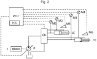
- Fig. 2 shows the exemplary embedding of the control block CB for controlling a working tool.
- the adjustable hydraulic pump P is driven mechanically by a motor, e.g. an internal combustion engine or electric motor E.
- a motor e.g. an internal combustion engine or electric motor E.
- Hydraulic fluid is supplied to the hydraulic control block CB via the pump P.
- the position of the control piston in the control block CB (according to Figure 1 ), for example via electro-hydraulic pilot valves (not shown).
- the corresponding hydraulic fluid quantity is delivered to the relevant hydraulic cylinder of the work tool LC, TC and thus leads to the desired movement of, for example, the lifting arm and/or bucket/fork of the work machine.
- the control slide adjustment is carried out by the VCU control unit.
- the input variables M1, M2 for the cylinder pressure on the base and rod side of the cylinder and M5, for example the angle of rotation from a rotary angle sensor on the lifting cylinder LC, which is arranged, for example, on the lifting arm, are read into the VCU control unit.
- a rotary angle sensor on the lifting cylinder LC which is arranged, for example, on the lifting arm
- the input variables M3, M4 for the cylinder pressure on the base and rod side of the cylinder and M6, for example the angle of rotation from a rotary angle sensor on the tilting cylinder TC, which is arranged, for example, on the deflection lever, are read into the VCU control unit.
- a pushing load means that the direction of action of the hydraulic pressure in the cylinder (resulting from the cylinder base and rod-side pressure) and the direction of movement of the cylinder are in the same direction.
- a pulling load means that the direction of action of the hydraulic pressure in the cylinder (resulting from the cylinder base and rod-side pressure) and the direction of movement of the cylinder are in the opposite direction.
- the pump pressure regulator PCU of the pump can be either a separate component or integrated into the VCU.
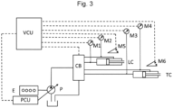
- Fig. 3 shows a pump control unit PCU, which is designed as a separate component.
Landscapes
- Engineering & Computer Science (AREA)
- General Engineering & Computer Science (AREA)
- Mechanical Engineering (AREA)
- Mining & Mineral Resources (AREA)
- Civil Engineering (AREA)
- Structural Engineering (AREA)
- Physics & Mathematics (AREA)
- Fluid Mechanics (AREA)
- Chemical & Material Sciences (AREA)
- Analytical Chemistry (AREA)
- Operation Control Of Excavators (AREA)
- Fluid-Pressure Circuits (AREA)
Description
- Die vorliegende Erfindung betrifft eine mobile Arbeitsmaschine, insbesondere einen Radlader, mit einem vorzugsweise offenen Hydraulikkreislauf und mit einer Pumpe zur Förderung eines Hydraulikmediums durch den Hydraulikkreislauf sowie mit zumindest einem Steuerblock mit einer Zulaufsteuerkante und einer Ablaufsteuerkante zur Steuerung des Flusses des Hydraulikmediums, wobei die Arbeitsmaschine ein Arbeitswerkzeug und einen Zylinder zur Betätigung des Arbeitswerkzeugs aufweist und wobei der Zylinder einen Ablauf und einen Zulauf für das Hydraulikmedium aufweist, wobei der Ablauf mit der Ablaufsteuerkante und der Zulauf mit der Zulaufsteuerkante des Steuerblocks in Fluidverbindung stehen.
- Aus dem Stand der Technik ist es bekannt, Zylinderantriebe für Arbeitsmaschinen, wie z.B. für Radlader, mit Pumpen im offenen Kreislauf in Verbindung mit Steuerblöcken in hydraulischen Regelsystemen zu betreiben. Dies gilt vorzugsweise für Radlader mit LS (Load-Sensing) Systemen. Für diese Regelung ist ein erheblicher Energieaufwand erforderlich. Werden mehrere Verbraucher durch die Pumpe versorgt, kommen noch Verluste durch unterschiedliche Lastdrücke hinzu, da die Pumpe stets den Gesamtförderstrom mit dem Druck des lastdruckhöchsten Verbrauchers erzeugen muss, um dessen Funktion zu gewährleisten.
DE112016000086T5 offenbart eine gattungsgemäße mobile Arbeitsmaschine mit den Merkmalen des Oberbegriffes des Anspruch 1. - Denkbar ist es, mehrere Pumpen einzusetzen, die es ermöglichen, mehrere Drücke zu erzeugen. Durch eine variable Zuteilung von Kolbengruppen für verschiedene Verbraucher soll erreicht werden, dass die Pumpen jederzeit für jeden Verbraucher die erforderliche Ölmenge mit dem individuell zugehörigen Druck versorgen. Dies ermöglicht eine reine Verdrängersteuerung der Verbraucher, d.h. die Pumpen fördern die jeweils erforderliche Menge ohne hydraulische Regelung durch elektrische Vorgabe dieser Menge. Dadurch werden Verluste für unterschiedliche Lastdrücke und für die Regelung vermieden und die Energieeffizienz der Arbeitsmaschine wird gesteigert.
- Für drückende Lasten, wie z.B. beim Anheben der Schaufel des Radladers wird aus dem Fahrerwunsch in Form der Bedienhebelauslenkung oder dergleichen eine Wunschmenge ermittelt. Diese wird an die Pumpe weitergeleitet, die dann die Fördermenge bereitstellt. Der LS-Regelaufwand entfällt. Der Steuerblock wird voll geöffnet und nimmt an der Mengenzuteilung keinen Anteil mehr.
- Der vorliegenden Erfindung liegt die Aufgabe zugrunde, eine Arbeitsmaschine der eingangs genannten Art dahingehend weiterzubilden, dass diese besonders effizient arbeitet.
- Diese Aufgabe wird durch eine Arbeitsmaschine mit den Merkmalen des Anspruchs 1 gelöst.
- Danach ist vorgesehen, dass die Zulaufsteuerkante keine oder weniger Feinsteuerkerben als die Ablaufsteuerkante aufweist, die mit einer oder mehreren Feinsteuerkerben ausgestattet ist, so dass bei einer ziehenden Last am Arbeitswerkzeug die Ablaufsteuerkante die Ablaufmenge durch den Ablauf des Zylinders drosselt.
- Bei einer ziehenden Last, wie z.B. beim Kippen der Schaufel eines Radladers über den Kipppunkt hinaus, wird der Zylinder durch die Last gezogen, d.h. der Zylinder wird durch die äußere Kraft bewegt.
- In diesem Fall wird die Mengensteuerung für das Hydraulikmedium, insbesondere Öl, vom Steuerblock übernommen. Dieser verschließt die Ablaufsteuerkante des Steuerblocks entsprechend der gewünschten Bewegungsgeschwindigkeit des Arbeitswerkzeuges, die z.B. durch die Auslenkung des Fahrerbedienhebels vorgegeben wird, teilweise und drosselt auf diese Weise die Ablaufmenge aus dem Zylinder.
- An dieser Stelle wird darauf hingewiesen, dass der Begriff "Zylinder" allgemein für eine oder mehrere Kolben-Zylindereinheiten steht, wobei der Kolben in dem Zylinderraum beweglich aufgenommen ist und diesen in zumindest zwei Teilbereiche unterteilt, von denen einer den Ablauf und einer den Zulauf aufweist.
- Es können ein oder mehrere Sensoren vorgesehen sein, die die Druckverhältnisse erfassen.
- Auf der gegenüberliegenden Seite, d.h. im Bereich des sich bei ziehender Last vergrößernden Volumens des Zylinders wird ein bestimmter Mindestdruck aufrechterhalten, so dass die durch das Ausziehen des Zylinders entstehende Volumenvergrößerung befüllt wird. Die Menge wird über die voll geöffnete Steuerkante im Steuerblock nahezu verlustlos zugemessen.
- Es ist ein Druckregler vorgesehen, der mit der Pumpe derart zusammenwirkt, dass auf der Zylinderseite, auf der sich durch die ziehende Last eine Volumenvergrößerung ergibt, der Mindestdruck aufrechterhalten wird.
- Dabei kann es sich um einen elektrisch verstellbaren Druckregler der Pumpe handeln.
- Es kann eine Steuerung vorgesehen sein, die ausgebildet ist, die Bewegung des oder der Steuerblöcke zu steuern oder zu regeln.
- Vorzugsweise weist der Steuerblock eine Zulauf- und eine Ablaufsteuerung auf. Der Zulauf wird jedoch erfindungsgemäß durch die Fördermenge der Pumpe gesteuert und weist somit vorzugsweise keine Feinsteuerkerbe auf und öffnet aus der Mittellage schnell und auf den Vollquerschnitt. Es kann eines Steuerung vorhanden sein, die ausgebildet ist, die Fördermenge der Pumpe durch den Zulauf zu steuern oder zu regeln.
- Hingegen weist die Ablaufseite am Steuerblock die volle Funktionalität eines klassischen Steuerblocks auf und weist dementsprechend eine oder mehrere Feinsteuerkerben auf und ggf. reduzierte Querschnitte.
- Erfindungsgemäß kann somit ein klassischer Steuerblock zum Einsatz kommen, dessen Zulaufsteuerkanten vollständig entdrosselt sind. Die Funktion beschränkt sich auf die Zuordnung zur jeweiligen Zylinderseite (Wechsel der Bewegungsrichtung) und die ggf. erforderliche Ablaufdrosselung.
- Die Ablaufsteuerkante und die Zulaufsteuerkante können in einem Steuerblock vereinigt sein oder in aufgelöster Bauweise, d.h. in getrennten Steuerblöcken angeordnet sein.
- In einer weiteren Ausgestaltung der Erfindung weist die Arbeitsmaschine einen Hauptverbraucher und einen Zusatzverbraucher auf, wobei eine Steuerung vorhanden ist, die ausgebildet ist, dass bei einer ziehenden Last an dem Arbeitswerkzeug und bei einem geringeren Lastdruck des Zusatzverbrauchers als des Hauptverbrauchers die Ablaufsteuerkante des Hauptverbrauchers so weit schließt, dass Druck aufgestaut wird, der zur Betätigung des Zusatzverbrauchers ausreicht. Auch dies kann durch eine geeignete Steuerung erfolgen.
- Vorzugsweise werden für untergeordnete Zusatzfunktionen die Hauptversorgungen mit genutzt. Beispielsweise könnte die Hubversorgung eine Hochkippschaufel auskippen oder die Kippversorgung einen Niederhalter beaufschlagen, wodurch Bauaufwand eingespart wird. Diese Funktionen werden 3. oder ggf. 4. Steuerkreis etc. genannt, die üblicherweise eigene Schieber aufweisen.
- Wenn ein Druckniveau verschiedene Verbraucher versorgt, entsteht das Problem, dass der lastdruckniedrigste Verbraucher einen Hauptanteil der Menge schluckt und der lastdruckhöchste Verbraucher stehen bleibt, da das Öl bzw. das Hydraulikmedium stets den Weg des kleinsten Widerstandes wählt. Im Stand der Technik werden diese Druckunterschiede über Druckwaagen vernichtet und so durch Drosselung die gewünschte Bewegungsgeschwindigkeit eingestellt. Die Pumpe liefert den höchsten Lastdruck mit der Gesamtmenge.
- Um den Bauaufwand gering zu halten, werden der 3. und ggf. der 4. Steuerkreis mit dem Hydraulikkreis gemäß Anspruch 1 kombiniert.
- Dabei können folgende Fälle auftreten:
Der Lastdruck im 3. und ggf. 4. Steuerkreis ist geringer als der der Hauptfunktion: eine Druckwaage am 3. bzw. 4. Steuerkreis staut durch Rückmeldung des hohen Lastdrucks aus der Hauptfunktion den Druck soweit an, dass die Hauptfunktion nicht stehen bleibt, wie dies aus dem Stand der Technik bekannt ist. - Im zweiten Fall ist der Lastdruck im 3. und ggf. 4. Steuerkreis höher als der der Hauptfunktion, d.h. der Lastdruck des Zusatzverbrauchers ist höher als der des Hauptverbrauchers. Um zu erreichen, dass der oder die Zusatzverbraucher nicht zum Stehen kommen, wird erfindungsgemäß bei einer ziehenden Last die Ablaufsteuerkante des Hauptverbrauchers bzw. des Steuerblocks des Hauptverbrauchers so weit geschlossen, dass ausreichend Druck für den 3. und ggf. 4. Steuerkreis aufgebaut wird und der Zusatzverbraucher bewegt wird.
- Der Vorteil besteht darin, dass keine zusätzlichen Bauteile benötigt werden und solange die Hauptfunktion alleine genutzt wird, der volle energetische Vorteil genutzt werden kann.
- An dieser Stelle wird darauf hingewiesen, dass die Begriffe "ein" und "eine" nicht zwingend auf genau eines der Elemente verweisen, wenngleich dies eine mögliche Ausführung darstellt, sondern auch eine Mehrzahl der Elemente bezeichnen können. Ebenso schließt die Verwendung des Plurals auch das Vorhandensein des fraglichen Elementes in der Einzahl ein und umgekehrt umfasst der Singular auch mehrere der fraglichen Elemente.
- Weitere Einzelheiten und Vorteile der Erfindung werden anhand eines im Folgenden beschriebenen Ausführungsbeispiels näher erläutert. Dabei zeigen:
- Fig. 1
- eine schematische Darstellung des Hydraulikkreislaufs mit den unter-schiedlich ausgebildeten Zu- und Ablaufsteuerkanten eines Steuer-blocks,
- Fig. 2:
- eine schematische Darstellung einer Verschaltung eines Hebe- und ei-nes Kippzylinders für eine Schaufel einer Arbeitsmaschine, und
- Fig. 3:
- eine weitere schematische Darstellung einer Verschaltung eines Hebe-und eines Kippzylinders für eine Schaufel einer Arbeitsmaschine.
- Wird bei einem Radlader der Kipppunkt der Schaufel überschritten, zieht die Schaufel den Kippzylinder, d.h. der Kippzylinder wird durch die Schaufel bewegt.
- Die Mengensteuerung wird nun vom Steuerblock übernommen, der die Zylinderablaufsteuerkante entsprechend der gewünschten Bewegungsgeschwindigkeit teilweise verschließt, d.h. drosselt, so dass die Ablaufmenge und somit die Bewegungsgeschwindigkeit der Schaufel und des Zylinders eingestellt werden kann.
- Auf der anderen Seite, d.h. auf der Seite des sich vergrößernden Zylinderraums sorgt ein elektrisch verstellbarer Druckregler der Pumpe dafür, dass ein Mindestdruck aufrecht erhalten wird, so dass das durch das Ausziehen des Zylinders entstehende Volumen gefüllt wird. Dies erfolgt bei vollständig geöffneter Zulaufkante des Steuerblocks.
- Der Zulauf wird durch die Fördermenge der Pumpe gesteuert und weist somit keine Feinsteuerkerbe auf. Hingegen ist die Ablaufkante des Steuerblocks mit einer Feinsteuerkerbe versehen, so dass die Ablaufgeschwindigkeit einstellbar ist.
- An dieser Stelle wird darauf hingewiesen, dass der Begriff "Feinsteuerkerbe" nicht nur eine Feinsteuerkerbe als solche bezeichnet, sondern stellvertretend für jedes beliebige Drosselorgan steht.
-
Fig. 1 zeigt eine schematische Darstellung des Hydraulikkreislaufs mit den unterschiedlich ausgebildeten Zulaufsteuerkanten ZK und Ablaufsteuerkanten AK eines Steuerblocks CB. - Der Steuerblock CB ist dabei mit der Druckseite der Pumpe P, einem Tank T für Hydraulikmedium sowie der Bodenseite und der Stangenseite eines Zylinders verbunden. Der Steuerblock CB regelt dabei den Zu- und Ablauf von einem in dem Zylinder vorhandenen Hydraulikmedium, indem das bodenseitige B bzw. das stangenseitige A Zylinderreservoir über verstellbare Drosseleinheiten, den sogenannten Zulaufkanten ZK bzw. Ablaufkanten AK mit der Druckseite der Pumpe bzw. dem Tank fluidisch verbunden werden können.
- Kommt es nun zu einer auf den Zylinder wirkenden Zugkraft, so kommt es zur Aufgabe durch gezieltes Androsseln der Ablaufkante die kontinuierliche und gleichbleibende Zylinderbewegung sicherstellen. Ein unerwünschter Effekt könnte hier das Auftreten einer stark vom Fahrerwunsch abweichenden Bewegung sein.
- Am Beispiel eines Radladers kann sich ein solcher ungewünschter Effekt einstellen, wenn eine Radladerschaufel beim Abkippen ihren Kipppunkt überschritten hat und der vormals drückende Zylinder durch die Gewichtskraft der Schaufel und der darauf befindlichen Ladung zu einem gezogenen Zylinder wird. In anderen Worten zieht die nun von alleine herabkippende Schaufel den Zylinder aus (mit der in
Fig. 1 dargestellten Kraft F), die Ölfördermenge der Pumpe zur Zulaufseite (Kante) spielt für die Kontrollierbarkeit kaum mehr eine Rolle und die Bewegung muss über die Ablaufseite (Kante) dosiert werden. - Mit der vorliegenden Erfindung wird durch die Gestaltung der Ablaufkante AK und der Zulaufkante ZK in dem Steuerblock CB sichergestellt, dass auch in einem solchen Zustand ein ausreichend hoher Druck auf der Ablaufseite des Verbrauchers (Zylinders) vorhanden ist.
- In
Fig. 1 weist die Zulaufsteuerkante ZK in das bodenseitige Reservoir des Zylinders eine Form auf, bei der abrupt viel Fläche freigegeben wird, so dass ein entdrosselter Zulauf von der Pumpe P in das bodenseitige Reservoir B des Zylinders einströmen kann. - Anders sieht dies beim Ablauf des Hydraulikmediums aus dem stangenseitigen Reservoir A des Zylinders aus, da hier die Ablaufkante AK eine drosselnde Funktion besitzt, die bspw. durch einen linearen Verlauf der Kante geschaffen werden kann. Dadurch kann durch kleine Änderungen an der Schieberposition der Druck, beispielhaft auf der Stangenseite M4, effektiv und gut dosierbar aufgebaut werden. Hierdurch kann trotz verlustoptimierter Zulaufkante auch für fordernde Situationen ein sauberes Bewegungsverhalten gewährleistet werden.
- Für das leichtere Verständnis ist die Strömungsrichtung des Hydraulikmediums durch Pfeile in der
Fig. 1 dargestellt. -
Fig. 2 zeigt dabei die beispielhafte Einbettung des Steuerblocks CB zur Ansteuerung eines Arbeitswerkzeugs. - Der Antrieb der verstellbaren Hydraulikpumpe P erfolgt dabei mechanisch mit einem Motor, bspw. einem Verbrennungs- bzw. Elektromotor E.
- Es wird dem hydraulischen Steuerblock CB über die Pumpe P Hydraulikflüssigkeit zugeführt. Über eine Steuereinheit VCU wird die Position des Steuerkolbens im Steuerblock CB (entsprechend
Figur 1 ) eingestellt, beispielhaft über elektrohydraulische Vorsteuerventile (nicht dargestellt). Je nach Steuerkolbenstellung wird die entsprechende Hydraulikflüssigkeitsmenge an betreffende Hydraulikzylinder des Arbeitswerkzeugs LC, TC abgegeben und führt so zur gewünschten Bewegung von bspw. Hubarm und/oder Schaufel/Gabel der Arbeitsmaschine. - Die Steuerschieberverstellung übernimmt die Steuereinheit VCU. Dazu werden die Eingangsgrößen M1, M2 für den Zylinderdruck der Boden- und Stangenseite des Zylinders sowie M5 bspw. der Drehwinkel von einem Drehwinkelgeber des Hebezylinders LC, der bspw. am Hubarm angeordnet ist, in die Steuereinheit VCU eingelesen. Es wird darauf hingewiesen, dass abseits eines Drehwinkelgebers auch andere Positionserfassungssysteme in der Kinematik der Arbeitsmaschine eingesetzt werden könnten. Dazu werden die Eingangsgrößen M3, M4 für den Zylinderdruck der Boden- und Stangenseite des Zylindes sowie M6 bspw. der Drehwinkel von einem Drehwinkelgeber des Kippzylinders TC, bspw. am Umlenkhebel angeordnet, in die Steuereinheit VCU eingelesen.
- Die Beurteilung, ob eine ziehende oder eine drückende Last anliegt, erfolgt durch die Auswertung der Hub-Kippbewegung über betreffende Drehwinkelsensoren in Kombination mit den ermittelten Zylinderdrücken. Es erfolgt eine Verstellung des Steuerkolbens nach hinterlegter Ventilkennlinie. Drückende Last bedeutet, dass die Wirkrichtung von Hydraulikdruck im Zylinder (Resultierende aus Zylinder boden- und stangenseitigem Druck) und Bewegungsrichtung des Zylinders in dieselbe Richtung gehen. Ziehende Last bedeutet, dass die Wirkrichtung von Hydraulikdruck im Zylinder (Resultierende aus Zylinder boden- und stangenseitigem Druck) und die Bewegungsrichtung des Zylinders in die entgegengesetzte Richtung gehen.
- Der Pumpen-Druckregler PCU der Pumpe kann sowohl ein separates Bauteil bzw. in der VCU integriert sein.
-
Fig. 3 zeigt eine Pumpensteuereinheit PCU, die als separates Bauteil ausgeführt ist. -
- VCU
- Vehicle control unit
- PCU
- Pump control unit
- CB
- Control block/Steuerblock
- E
- Engine/Motor
- M1
- Drucksensor LC Lift Cylinder - Bodendruck
- M2
- Drucksensor LC Stangendruck
- M3
- Drucksensor TC Tilt Cylinder - Bodendruck
- M4
- Drucksensor TC Stangendruck
- M5
- Winkelsensor LC
- M6
- Winkelsensor TC
- P
- Pumpe
- AK
- Ablaufkante
- ZK
- Zulaufkante
- A
- stangenseitiges Reservoir
- B
- bodenseitiges Reservoir
- T
- Tank
- F
- Zugkraft auf Zylinderkolben
Claims (5)
- Mobile Arbeitsmaschine, insbesondere Radlader, miteinem Hydraulikkreislauf,einer Pumpe (P) zur Förderung eines Hydraulikmediums durch den Hydraulikkreislauf, undzumindest einem Steuerblock (CB) mit einer Zulaufsteuerkante (ZK) und einer Ablaufsteuerkante (AK) zur Steuerung des Flusses des Hydraulikmediums, wobeidie Arbeitsmaschine ein Arbeitswerkzeug und einen Zylinder zur Betätigung des Arbeitswerkzeugs aufweist,der Zylinder einen Ablauf und einen Zulauf für das Hydraulikmedium aufweist,der Ablauf mit der Ablaufsteuerkante (AK) und der Zulauf mit der Zulaufsteuerkante (ZK) in Fluidverbindung stehen, unddie Zulaufsteuerkante (ZK) keine oder weniger Feinsteuerkerben als die Ablaufsteuerkante (AK) aufweist und somit weitgehend entdrosselt arbeitet, während die Ablaufsteuerkante (AK) mit einer oder mehreren Feinsteuerkerben ausgestattet ist, so dass bei einer ziehenden Last am Arbeitswerkzeug die Ablaufsteuerkante (AK) die Ablaufmenge durch den Ablauf des Zylinders drosselt,dadurch gekennzeichnet, dassein Druckregler vorgesehen ist, der mit der Pumpe (P) derart zusammenwirkt, dass auf der Zylinderseite, auf der sich durch die ziehende Last eine Volumenvergrößerung ergibt, ein Mindestdruck aufrechterhalten wird.
- Mobile Arbeitsmaschine nach Anspruch 1, dadurch gekennzeichnet, dass eine Steuerung vorgesehen ist, die ausgebildet ist, die Bewegung des oder der Steuerblöcke (CB) zu steuern.
- Mobile Arbeitsmaschine nach Anspruch 1 oder 2, dadurch gekennzeichnet, dass eine Pumpensteuerung vorgesehen ist, die ausgebildet ist, die Fördermenge durch die Pumpe (P) zu steuern.
- Mobile Arbeitsmaschine nach einem der vorhergehenden Ansprüche, dadurch gekennzeichnet, dass es sich bei dem Druckregler um einen elektrisch verstellbaren Druckregler der Pumpe (P) handelt.
- Mobile Arbeitsmaschine nach einem der vorhergehenden Ansprüche, dadurch gekennzeichnet, dass die Arbeitsmaschine einen Hauptverbraucher und einen Zusatzverbraucher aufweist und dass eine Steuerung vorhanden ist, die ausgebildet ist, dass bei einem geringeren Lastdruck des Zusatzverbrauchers als des Hauptverbrauchers die Ablaufsteuerkante (AK) des Hauptverbrauchers so weit schließt, dass Druck aufgestaut wird, der zur Betätigung des Zusatzverbrauchers ausreicht.
Applications Claiming Priority (2)
| Application Number | Priority Date | Filing Date | Title |
|---|---|---|---|
| DE102019117118 | 2019-06-25 | ||
| PCT/EP2020/067808 WO2020260450A1 (de) | 2019-06-25 | 2020-06-25 | Mobile arbeitsmaschine |
Publications (2)
| Publication Number | Publication Date |
|---|---|
| EP3987119A1 EP3987119A1 (de) | 2022-04-27 |
| EP3987119B1 true EP3987119B1 (de) | 2024-10-09 |
Family
ID=71409378
Family Applications (1)
| Application Number | Title | Priority Date | Filing Date |
|---|---|---|---|
| EP20735516.5A Active EP3987119B1 (de) | 2019-06-25 | 2020-06-25 | Mobile arbeitsmaschine |
Country Status (4)
| Country | Link |
|---|---|
| US (1) | US12195950B2 (de) |
| EP (1) | EP3987119B1 (de) |
| DE (1) | DE102020116738A1 (de) |
| WO (1) | WO2020260450A1 (de) |
Family Cites Families (5)
| Publication number | Priority date | Publication date | Assignee | Title |
|---|---|---|---|---|
| US6397890B1 (en) * | 1999-02-15 | 2002-06-04 | Case Corp. | Variable metering fluid control valve |
| DE102006002920A1 (de) | 2006-01-20 | 2007-07-26 | Robert Bosch Gmbh | Hydraulische Steueranordnung |
| JP6245611B2 (ja) * | 2014-04-18 | 2017-12-13 | キャタピラー エス エー アール エル | 制御装置および作業機械 |
| DE112016000086B4 (de) * | 2016-05-31 | 2018-12-27 | Komatsu Ltd. | Schieberventil und arbeitsfahrzeug |
| US11841084B2 (en) * | 2020-04-06 | 2023-12-12 | Parker-Hannifin Corporation | Valve spool with flow force mitigation features |
-
2020
- 2020-06-25 EP EP20735516.5A patent/EP3987119B1/de active Active
- 2020-06-25 US US17/620,131 patent/US12195950B2/en active Active
- 2020-06-25 WO PCT/EP2020/067808 patent/WO2020260450A1/de not_active Ceased
- 2020-06-25 DE DE102020116738.5A patent/DE102020116738A1/de active Pending
Also Published As
| Publication number | Publication date |
|---|---|
| WO2020260450A1 (de) | 2020-12-30 |
| US20220251804A1 (en) | 2022-08-11 |
| US12195950B2 (en) | 2025-01-14 |
| DE102020116738A1 (de) | 2020-12-31 |
| WO2020260450A8 (de) | 2021-03-11 |
| EP3987119A1 (de) | 2022-04-27 |
Similar Documents
| Publication | Publication Date | Title |
|---|---|---|
| EP2541072B1 (de) | Steueranordnung und Verfahren zum Ansteuern von mehreren hydraulischen Verbrauchern | |
| EP2171285B1 (de) | Hydraulische steueranordnung | |
| EP1915538B1 (de) | Schaltung zur ansteuerung eines doppeltwirkenden hydraulischen antriebszylinders | |
| DE112012004874B4 (de) | Hydraulisches Antriebssystem | |
| DE102020206343A1 (de) | Verfahren zur Kalibrierung eines elektroproportional verstellbaren Stetigventils | |
| DE102004063044B4 (de) | Hydraulische Steuerung | |
| DE112017003054B4 (de) | Hydraulisches ansteuersystem | |
| EP1450048A1 (de) | Ventilanordnung | |
| EP1574474A2 (de) | Hydraulische Anordnung | |
| EP3759357B1 (de) | Ventilanordnung zur druckmittelversorgung eines hydraulischen verbrauchers | |
| EP2225470A1 (de) | Ventilanordnung | |
| DE102012207422A1 (de) | Hydraulische Steueranordnung mit Lastdruckminderungund hydraulischer Ventilblock dafür | |
| EP2142808B1 (de) | Hydraulische steueranordnung | |
| WO2007087962A1 (de) | Hydraulische steueranordnung mit regeneration | |
| AT516181B1 (de) | Hydraulikaggregat | |
| DE102020204254A1 (de) | Hydraulisches System | |
| DE102011107218B4 (de) | Hydrostatisches Antriebssystem | |
| DE102008064064A1 (de) | Hydraulische Steueranordnung | |
| DE4418442A1 (de) | Meßanlage für eine hydraulische Last und Verfahren für ihren Betrieb | |
| WO2016091528A1 (de) | Hydraulische ventilanordnung, hydraulischer ventilblock mit einer derartigen ventilanordnung, und hydraulischer antrieb mit einem derartigen ventilblock | |
| EP2891805A2 (de) | Steueranordnung und Steuerventil für eine derartige Steueranordnung | |
| EP2441966B1 (de) | Ansteuereinrichtung für hydraulische Verbraucher | |
| DE10216119A1 (de) | Hydraulische Steueranordnung in Load-Sensing Technik | |
| EP2513491B1 (de) | Ventilanordnung zur ansteuerung eines verbrauchers | |
| EP1576241B1 (de) | Steuereinrichtung für ein arbeitsgerät mit einer ausleger gehaltenen schaufel |
Legal Events
| Date | Code | Title | Description |
|---|---|---|---|
| STAA | Information on the status of an ep patent application or granted ep patent |
Free format text: STATUS: UNKNOWN |
|
| STAA | Information on the status of an ep patent application or granted ep patent |
Free format text: STATUS: THE INTERNATIONAL PUBLICATION HAS BEEN MADE |
|
| PUAI | Public reference made under article 153(3) epc to a published international application that has entered the european phase |
Free format text: ORIGINAL CODE: 0009012 |
|
| STAA | Information on the status of an ep patent application or granted ep patent |
Free format text: STATUS: REQUEST FOR EXAMINATION WAS MADE |
|
| 17P | Request for examination filed |
Effective date: 20220119 |
|
| AK | Designated contracting states |
Kind code of ref document: A1 Designated state(s): AL AT BE BG CH CY CZ DE DK EE ES FI FR GB GR HR HU IE IS IT LI LT LU LV MC MK MT NL NO PL PT RO RS SE SI SK SM TR |
|
| DAV | Request for validation of the european patent (deleted) | ||
| DAX | Request for extension of the european patent (deleted) | ||
| P01 | Opt-out of the competence of the unified patent court (upc) registered |
Effective date: 20230608 |
|
| STAA | Information on the status of an ep patent application or granted ep patent |
Free format text: STATUS: EXAMINATION IS IN PROGRESS |
|
| 17Q | First examination report despatched |
Effective date: 20230929 |
|
| GRAP | Despatch of communication of intention to grant a patent |
Free format text: ORIGINAL CODE: EPIDOSNIGR1 |
|
| STAA | Information on the status of an ep patent application or granted ep patent |
Free format text: STATUS: GRANT OF PATENT IS INTENDED |
|
| INTG | Intention to grant announced |
Effective date: 20240503 |
|
| GRAS | Grant fee paid |
Free format text: ORIGINAL CODE: EPIDOSNIGR3 |
|
| GRAA | (expected) grant |
Free format text: ORIGINAL CODE: 0009210 |
|
| STAA | Information on the status of an ep patent application or granted ep patent |
Free format text: STATUS: THE PATENT HAS BEEN GRANTED |
|
| AK | Designated contracting states |
Kind code of ref document: B1 Designated state(s): AL AT BE BG CH CY CZ DE DK EE ES FI FR GB GR HR HU IE IS IT LI LT LU LV MC MK MT NL NO PL PT RO RS SE SI SK SM TR |
|
| RAP3 | Party data changed (applicant data changed or rights of an application transferred) |
Owner name: LIEBHERR-WERK BISCHOFSHOFEN GMBH |
|
| REG | Reference to a national code |
Ref country code: CH Ref legal event code: EP |
|
| REG | Reference to a national code |
Ref country code: DE Ref legal event code: R096 Ref document number: 502020009434 Country of ref document: DE |
|
| REG | Reference to a national code |
Ref country code: IE Ref legal event code: FG4D Free format text: LANGUAGE OF EP DOCUMENT: GERMAN |
|
| REG | Reference to a national code |
Ref country code: LT Ref legal event code: MG9D |
|
| REG | Reference to a national code |
Ref country code: NL Ref legal event code: MP Effective date: 20241009 |
|
| PG25 | Lapsed in a contracting state [announced via postgrant information from national office to epo] |
Ref country code: NL Free format text: LAPSE BECAUSE OF FAILURE TO SUBMIT A TRANSLATION OF THE DESCRIPTION OR TO PAY THE FEE WITHIN THE PRESCRIBED TIME-LIMIT Effective date: 20241009 |
|
| PG25 | Lapsed in a contracting state [announced via postgrant information from national office to epo] |
Ref country code: NL Free format text: LAPSE BECAUSE OF FAILURE TO SUBMIT A TRANSLATION OF THE DESCRIPTION OR TO PAY THE FEE WITHIN THE PRESCRIBED TIME-LIMIT Effective date: 20241009 |
|
| PG25 | Lapsed in a contracting state [announced via postgrant information from national office to epo] |
Ref country code: HR Free format text: LAPSE BECAUSE OF FAILURE TO SUBMIT A TRANSLATION OF THE DESCRIPTION OR TO PAY THE FEE WITHIN THE PRESCRIBED TIME-LIMIT Effective date: 20241009 Ref country code: IS Free format text: LAPSE BECAUSE OF FAILURE TO SUBMIT A TRANSLATION OF THE DESCRIPTION OR TO PAY THE FEE WITHIN THE PRESCRIBED TIME-LIMIT Effective date: 20250209 Ref country code: PT Free format text: LAPSE BECAUSE OF FAILURE TO SUBMIT A TRANSLATION OF THE DESCRIPTION OR TO PAY THE FEE WITHIN THE PRESCRIBED TIME-LIMIT Effective date: 20250210 |
|
| PG25 | Lapsed in a contracting state [announced via postgrant information from national office to epo] |
Ref country code: FI Free format text: LAPSE BECAUSE OF FAILURE TO SUBMIT A TRANSLATION OF THE DESCRIPTION OR TO PAY THE FEE WITHIN THE PRESCRIBED TIME-LIMIT Effective date: 20241009 |
|
| PG25 | Lapsed in a contracting state [announced via postgrant information from national office to epo] |
Ref country code: BG Free format text: LAPSE BECAUSE OF FAILURE TO SUBMIT A TRANSLATION OF THE DESCRIPTION OR TO PAY THE FEE WITHIN THE PRESCRIBED TIME-LIMIT Effective date: 20241009 |
|
| PG25 | Lapsed in a contracting state [announced via postgrant information from national office to epo] |
Ref country code: ES Free format text: LAPSE BECAUSE OF FAILURE TO SUBMIT A TRANSLATION OF THE DESCRIPTION OR TO PAY THE FEE WITHIN THE PRESCRIBED TIME-LIMIT Effective date: 20241009 |
|
| PG25 | Lapsed in a contracting state [announced via postgrant information from national office to epo] |
Ref country code: NO Free format text: LAPSE BECAUSE OF FAILURE TO SUBMIT A TRANSLATION OF THE DESCRIPTION OR TO PAY THE FEE WITHIN THE PRESCRIBED TIME-LIMIT Effective date: 20250109 |
|
| PG25 | Lapsed in a contracting state [announced via postgrant information from national office to epo] |
Ref country code: LV Free format text: LAPSE BECAUSE OF FAILURE TO SUBMIT A TRANSLATION OF THE DESCRIPTION OR TO PAY THE FEE WITHIN THE PRESCRIBED TIME-LIMIT Effective date: 20241009 Ref country code: GR Free format text: LAPSE BECAUSE OF FAILURE TO SUBMIT A TRANSLATION OF THE DESCRIPTION OR TO PAY THE FEE WITHIN THE PRESCRIBED TIME-LIMIT Effective date: 20250110 |
|
| PG25 | Lapsed in a contracting state [announced via postgrant information from national office to epo] |
Ref country code: PL Free format text: LAPSE BECAUSE OF FAILURE TO SUBMIT A TRANSLATION OF THE DESCRIPTION OR TO PAY THE FEE WITHIN THE PRESCRIBED TIME-LIMIT Effective date: 20241009 |
|
| PG25 | Lapsed in a contracting state [announced via postgrant information from national office to epo] |
Ref country code: RS Free format text: LAPSE BECAUSE OF FAILURE TO SUBMIT A TRANSLATION OF THE DESCRIPTION OR TO PAY THE FEE WITHIN THE PRESCRIBED TIME-LIMIT Effective date: 20250109 |
|
| PG25 | Lapsed in a contracting state [announced via postgrant information from national office to epo] |
Ref country code: SM Free format text: LAPSE BECAUSE OF FAILURE TO SUBMIT A TRANSLATION OF THE DESCRIPTION OR TO PAY THE FEE WITHIN THE PRESCRIBED TIME-LIMIT Effective date: 20241009 |
|
| PG25 | Lapsed in a contracting state [announced via postgrant information from national office to epo] |
Ref country code: DK Free format text: LAPSE BECAUSE OF FAILURE TO SUBMIT A TRANSLATION OF THE DESCRIPTION OR TO PAY THE FEE WITHIN THE PRESCRIBED TIME-LIMIT Effective date: 20241009 |
|
| PGFP | Annual fee paid to national office [announced via postgrant information from national office to epo] |
Ref country code: GB Payment date: 20250621 Year of fee payment: 6 |
|
| REG | Reference to a national code |
Ref country code: DE Ref legal event code: R097 Ref document number: 502020009434 Country of ref document: DE |
|
| PG25 | Lapsed in a contracting state [announced via postgrant information from national office to epo] |
Ref country code: EE Free format text: LAPSE BECAUSE OF FAILURE TO SUBMIT A TRANSLATION OF THE DESCRIPTION OR TO PAY THE FEE WITHIN THE PRESCRIBED TIME-LIMIT Effective date: 20241009 |
|
| PGFP | Annual fee paid to national office [announced via postgrant information from national office to epo] |
Ref country code: FR Payment date: 20250617 Year of fee payment: 6 |
|
| PG25 | Lapsed in a contracting state [announced via postgrant information from national office to epo] |
Ref country code: RO Free format text: LAPSE BECAUSE OF FAILURE TO SUBMIT A TRANSLATION OF THE DESCRIPTION OR TO PAY THE FEE WITHIN THE PRESCRIBED TIME-LIMIT Effective date: 20241009 |
|
| PGFP | Annual fee paid to national office [announced via postgrant information from national office to epo] |
Ref country code: AT Payment date: 20250618 Year of fee payment: 6 |
|
| PG25 | Lapsed in a contracting state [announced via postgrant information from national office to epo] |
Ref country code: SK Free format text: LAPSE BECAUSE OF FAILURE TO SUBMIT A TRANSLATION OF THE DESCRIPTION OR TO PAY THE FEE WITHIN THE PRESCRIBED TIME-LIMIT Effective date: 20241009 |
|
| PG25 | Lapsed in a contracting state [announced via postgrant information from national office to epo] |
Ref country code: CZ Free format text: LAPSE BECAUSE OF FAILURE TO SUBMIT A TRANSLATION OF THE DESCRIPTION OR TO PAY THE FEE WITHIN THE PRESCRIBED TIME-LIMIT Effective date: 20241009 |
|
| PG25 | Lapsed in a contracting state [announced via postgrant information from national office to epo] |
Ref country code: IT Free format text: LAPSE BECAUSE OF FAILURE TO SUBMIT A TRANSLATION OF THE DESCRIPTION OR TO PAY THE FEE WITHIN THE PRESCRIBED TIME-LIMIT Effective date: 20241009 |
|
| PLBE | No opposition filed within time limit |
Free format text: ORIGINAL CODE: 0009261 |
|
| STAA | Information on the status of an ep patent application or granted ep patent |
Free format text: STATUS: NO OPPOSITION FILED WITHIN TIME LIMIT |
|
| PG25 | Lapsed in a contracting state [announced via postgrant information from national office to epo] |
Ref country code: SE Free format text: LAPSE BECAUSE OF FAILURE TO SUBMIT A TRANSLATION OF THE DESCRIPTION OR TO PAY THE FEE WITHIN THE PRESCRIBED TIME-LIMIT Effective date: 20241009 |
|
| 26N | No opposition filed |
Effective date: 20250710 |
|
| PGFP | Annual fee paid to national office [announced via postgrant information from national office to epo] |
Ref country code: DE Payment date: 20250630 Year of fee payment: 6 |
|
| REG | Reference to a national code |
Ref country code: CH Ref legal event code: H13 Free format text: ST27 STATUS EVENT CODE: U-0-0-H10-H13 (AS PROVIDED BY THE NATIONAL OFFICE) Effective date: 20260127 |
|
| PG25 | Lapsed in a contracting state [announced via postgrant information from national office to epo] |
Ref country code: MC Free format text: LAPSE BECAUSE OF FAILURE TO SUBMIT A TRANSLATION OF THE DESCRIPTION OR TO PAY THE FEE WITHIN THE PRESCRIBED TIME-LIMIT Effective date: 20241009 |
|
| PG25 | Lapsed in a contracting state [announced via postgrant information from national office to epo] |
Ref country code: LU Free format text: LAPSE BECAUSE OF NON-PAYMENT OF DUE FEES Effective date: 20250625 |
|
| REG | Reference to a national code |
Ref country code: BE Ref legal event code: MM Effective date: 20250630 |
|
| PG25 | Lapsed in a contracting state [announced via postgrant information from national office to epo] |
Ref country code: IE Free format text: LAPSE BECAUSE OF NON-PAYMENT OF DUE FEES Effective date: 20250625 |
|
| PG25 | Lapsed in a contracting state [announced via postgrant information from national office to epo] |
Ref country code: BE Free format text: LAPSE BECAUSE OF NON-PAYMENT OF DUE FEES Effective date: 20250630 |
|
| PG25 | Lapsed in a contracting state [announced via postgrant information from national office to epo] |
Ref country code: CH Free format text: LAPSE BECAUSE OF NON-PAYMENT OF DUE FEES Effective date: 20250630 |