EP3985380A1 - Method for evaluating delayed fracture of metal material - Google Patents
Method for evaluating delayed fracture of metal material Download PDFInfo
- Publication number
- EP3985380A1 EP3985380A1 EP20853795.1A EP20853795A EP3985380A1 EP 3985380 A1 EP3985380 A1 EP 3985380A1 EP 20853795 A EP20853795 A EP 20853795A EP 3985380 A1 EP3985380 A1 EP 3985380A1
- Authority
- EP
- European Patent Office
- Prior art keywords
- chloride
- air atmosphere
- immersion
- metal material
- delayed fracture
- Prior art date
- Legal status (The legal status is an assumption and is not a legal conclusion. Google has not performed a legal analysis and makes no representation as to the accuracy of the status listed.)
- Pending
Links
Images
Classifications
-
- G—PHYSICS
- G01—MEASURING; TESTING
- G01N—INVESTIGATING OR ANALYSING MATERIALS BY DETERMINING THEIR CHEMICAL OR PHYSICAL PROPERTIES
- G01N17/00—Investigating resistance of materials to the weather, to corrosion, or to light
- G01N17/02—Electrochemical measuring systems for weathering, corrosion or corrosion-protection measurement
-
- G—PHYSICS
- G01—MEASURING; TESTING
- G01N—INVESTIGATING OR ANALYSING MATERIALS BY DETERMINING THEIR CHEMICAL OR PHYSICAL PROPERTIES
- G01N17/00—Investigating resistance of materials to the weather, to corrosion, or to light
- G01N17/006—Investigating resistance of materials to the weather, to corrosion, or to light of metals
-
- G—PHYSICS
- G01—MEASURING; TESTING
- G01N—INVESTIGATING OR ANALYSING MATERIALS BY DETERMINING THEIR CHEMICAL OR PHYSICAL PROPERTIES
- G01N33/00—Investigating or analysing materials by specific methods not covered by groups G01N1/00 - G01N31/00
- G01N33/20—Metals
-
- G—PHYSICS
- G01—MEASURING; TESTING
- G01N—INVESTIGATING OR ANALYSING MATERIALS BY DETERMINING THEIR CHEMICAL OR PHYSICAL PROPERTIES
- G01N17/00—Investigating resistance of materials to the weather, to corrosion, or to light
- G01N17/002—Test chambers
Definitions
- the present invention relates to a method for evaluating delayed fracture of a processed metal material used in an environment which is low-temperature high-humidity and in which de-icing salt being high in chloride deposits to the metal material.
- the hydrogen embrittlement is also referred to as delayed fracture and is a phenomenon that suddenly breaks a high-strength part in an embrittling manner substantially without plastic deformation in appearance when time elapses while the high-strength material part is subjected to static load stress.
- An increase in the amount of penetration of hydrogen into the material induces the occurrences of delayed fracture, and a delayed fracture sensitivity increases as the strength of the material increases.
- embrittlement may occur even in an atmospheric corrosion environment in which the hydrogen penetration amount is small.
- Automobiles are used in various environments and may be used in a de-icing salt applied region which is a high-humidity environment and in which, for example, de-icing salt being high in chloride deposits to the automobiles.
- a de-icing salt applied region which is a high-humidity environment and in which, for example, de-icing salt being high in chloride deposits to the automobiles.
- the delayed fracture characteristics in the de-icing salt applied region be evaluated.
- testing results of the delayed fracture characteristics under an actual environment in the de-icing salt applied region are different from testing results of the delayed fracture characteristics by using the techniques described in Patent Literatures 1 to 3.
- Patent Literatures 1 to 3 With the techniques of Patent Literatures 1 to 3, the delayed fracture characteristics under the low-temperature high-humidity and high-chloride environment cannot be accurately evaluated.
- the present invention has been made in view of the above-described problem, and an object of the present invention is to provide a method for evaluating delayed fracture characteristics of a metal material with which the delayed fracture characteristics under a low-temperature high-humidity and high-chloride environment can be accurately evaluated.
- the inventors of the present invention have achieved the above-described objective and the gist is as follows.
- delayed fracture characteristic can be accurately evaluated based on a processed condition of the processed metal material in an environment in which de-icing salt being high in chloride deposits in a low-temperature high-humidity atmosphere.
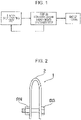
- Fig. 1 is a process diagram illustrating a preferred embodiment of a method for evaluating delayed fracture of a metal material according to the present invention.
- Fig. 2 is a schematic diagram illustrating an example of test specimens used for the method for evaluating delayed fracture.
- Fig. 1 is a process diagram illustrating a preferred embodiment of a method for evaluating delayed fracture of a metal material according to the present invention.
- the method for evaluating delayed fracture of a metal material illustrated in Fig. 1 evaluates delayed fracture characteristics, due to corrosion, of a metal material used under an environment which is a low-temperature high-humidity environment and in which a de-icing agent or other, being high in chloride, deposits to the metal material such as, for example, a de-icing salt applied region.
- the method for evaluating delayed fracture of a metal material is performed by performing step (A): a salt depositing step and step (B): a stationary step in an air atmosphere once or a plurality of times.
- de-icing agents include NaCl or CaCl 2 such as rock salt or common salt as the main component.
- de-icing agents such as, for example, organic de-icing agents or the like that do not include chloride are not included in the de-icing salt.
- Step (A) is a depositing step that causes a chloride component to deposit to the metal material.
- the chloride component includes an aqueous solution including a component that mainly includes chloride ions.
- the chloride component is maintained as an aqueous solution at a test temperature. A chloride component that becomes solid at the test temperature is not suitable for the testing.
- the component that mainly includes chloride ions refers to, for example, Cl ions in salt that includes Cl ions of NaCl, MgCl 2 , CaCl 2 , and the like.
- the component caused to deposit to the metal material is preferably a component mainly including NaCl.
- the term "mainly including” refers to a case where the object occupies equal to or greater than 50% in wt % except for moisture.
- the component mainly including chloride ions may include only chloride (one or more types of NaCl, MgCl 2 , CaCl 2 , and the like) or may include a component other than chloride. Examples of the component other than chloride include, but not limited to, sulfide and a nitric acid compound included in the environment, urea mixed with the de-icing agent to be applied, and so forth.
- the amount of chloride caused to deposit to the metal material is set to 1000 to 100000 mg/m 2 .
- This amount of chloride corresponds to the amount of chloride estimated for the actual environment.
- the amount of chloride smaller than 1000 mg/m 2 is unlikely in the actual environment of the de-icing salt applied region where the chloride component is actively supplied and far from the actual environment.
- the amount of chloride smaller than 1000 mg/m 2 slows down the state of corrosion which mainly affect the penetration of hydrogen. Accordingly, this amount of chloride smaller than 1000 mg/m 2 is not suitable for the evaluation of delayed fracture.
- a thicker water film is formed due to moisture absorption from an atmosphere.
- the amount of chloride is required to be about 1000 to 100000 mg/m 2 .
- the amount of chloride is preferably greater than or equal to 3000 mg/m 2 , and more preferably, greater than or equal to 8000 mg/m 2 and smaller than or equal to 30000 mg/m 2 .
- a method for causing the component mainly including chloride ions to deposit to the surface of the metal material is not particularly limited, typically, a method in which a solution including the component mainly including chloride ions is caused to deposit to the surface of the metal material is adopted.
- examples of this method include, for example, the following: immersion in which a test specimen is immersed in and is taken out from a solution to cause the component mainly including chloride ions to deposit to the surface of the steel sheet; a method in which a solution including a component mainly including chloride ions (typically, an aqueous solution such as salt water) is applied to the metal material by spraying or showering; a method in which very small droplets are caused to deposit by atomizing; and a method in which a predetermined amount of salt water are dripped with a pipette.
- the droplets in the spraying and the showering are equal to or greater than 50 ⁇ m, and the droplets in the atomizing are equal to or smaller than 50 ⁇ m.
- the spraying refers to a manual technique and the showering refers to an electrical technique. There is not much difference in finish between the spraying and the showering.
- the amount of chloride can be calculated by dividing the difference in mass between the metal material before the deposition and the metal material after the deposition by the area of a material to be tested. Furthermore, in the case of varying the amount of chloride, control can be performed by, for example, varying the concentration of the solution including the component mainly including chloride ions or, when the spraying application method is used, varying the weight of the amount of chloride in the solution applied to the metal material.
- Time for performing step (A) is preferably within 10 minutes. When this time exceeds 10 minutes, it is thought that corrosion of the metal material is in progress without controlling the temperature and humidity. Accordingly, step (A) is preferably performed within time as short as possible, for example, about one minute.
- Step B is a step in which the metal material having undergone step (A) is left stationary under an air atmosphere.
- the air atmosphere means a state in which the thickness of the water film is smaller than or equal to 10 mm.
- step (B) when the testing is performed in such an immersion environment where the solution volume to specimen area ratio with respect to the surface of the steel sheet is, for example, greater than or equal to 5 ml/cm 2 , dispersion of oxygen ascribable to corrosion significantly changes from that in the atmosphere, and accordingly, corrosion is different from corrosion in the actual environment.
- the test specimen is left stationary in the air atmosphere where the temperature and humidity are controlled.
- Step (B) is performed in a fixed environment without varying the relative humidity. When the relative humidity is fixed, an environment in which the surface of the steel sheet remains wet due to deposition of an aqueous solution including snow, ice, sleet, or the like that includes de-icing salt can be simulated.
- the humidity be fixed to the following values for corresponding types of salt: in the case where a salt mainly including NaCl is used, the relative humidity is higher than or equal to 75% RH; in the case where a salt mainly including MgCl 2 is used, the relative humidity is higher than or equal to 33% RH; and in the case where a salt mainly including KCl is used, the relative humidity is higher than or equal to 84% RH.
- the upper limit of the moisture absorption is 98%.
- a deliquescence phenomenon refers to a phenomenon in which salt absorbs water vapor in the atmosphere in a high humidity environment and becomes an aqueous solution.
- a water film is formed by the deliquescence of the salt in addition to the adsorption of water molecules corresponding to the relative humidity.
- the air atmosphere is maintained at a humidity higher than or equal to a humidity at which the absorption of moisture (deliquescence) of the added chloride occurs.
- the average of temperatures of the air atmosphere in step (B) be -50 to 10°C, and it is also required that a control range of the temperature be within ⁇ 5°C. It has been found that, under a condition in which the temperature of the air atmosphere exceeds 10°C, the delayed fracture characteristics in a low-temperature environment cannot be correctly evaluated. Regarding this, when the temperature of the air atmosphere exceeds 10°C, a corrosion speed of the steel sheet increases, the surface of the steel sheet changes, and stress of the surface becomes relaxed. Since the ratio of the amount of hydrogen penetrating into the steel material contributing to delayed fracture is decreased, the delayed fracture characteristics for the same amount of corrosion is different. This is not preferable.
- Steps (A) and (B) are performed once or a plurality of times.
- steps (A) and (B) described above it is required to process the metal material.
- a method for processing include, for example, bending, bulging, stretching, and so forth.
- the method for applying the stress include a method for fixing the metal material in a shape formed by applying the stress with bolts, a method for evaluating by using residual stress remaining after processing, and so forth.
- Test specimens were fabricated from different steel grades A, B, C, D having a thickness of 1.4 mm.
- the delayed fracture characteristics were evaluated by using the fabricated test specimens.
- the components of the steel grades A, B, C, D are described in Table 1 below.
- Fig. 2 is a schematic diagram illustrating an example of the test specimens for evaluating delayed fracture.
- the above-described steel sheets for testing were immersed in toluene, subjected to ultrasonic cleaning for five minutes, and then bent 180° as illustrated in Fig. 2 .
- the steel sheet in this state were constrained with a bolt BB and a nut BN to fabricate a test specimen 1.
- This test specimen 1 for evaluating delayed fracture has a bent portion 2 having a bend radius R of 4 to 9 mm, and a fastening width is 2R that is twice the bend radius R.
- a plurality of test specimens 1 were prepared such that bend radius of bent portions 2 of the different test specimens 1 was varied in six steps from each other by 1 mm.
- the bend radius R is small, the likelihood of cracking of the test specimen 1 increases due to large applied load.
- the bend radius R is large, the likelihood of cracking of the test specimen 1 decreases due to small applied load.
- test specimens 1 of the steel grades A, B both actual-environment testing in which crack testing was performed in an actual environment of an actual de-icing salt applied region and testing by using the method for evaluating delayed fracture of a metal material illustrated in Fig. 1 were performed.
- test specimens 1 of the steel grades C, D the testing by using the method for evaluating delayed fracture of a metal material illustrated in Fig. 1 was performed.
- each of the test specimens was placed in a lower portion of a moving body that moved every day on roads on which de-icing salt was applied. These test specimens were collected 60th days after the start of the testing. The test specimens were placed in the lower portion of the moving body because this portion is subjected to the effect of the de-icing salt. Results of the testing are described in Table 2 below.
- the maximum bend radius with which cracking occurred during the testing is defined as a boundary for cracking and defined as a bend radius limit in the actual environment. [Table 2] No.
- the method for evaluating delayed fracture of a metal material illustrated in Fig. 1 was used, and the test duration at this time was 60 days at the maximum.
- the maximum bend radius with which cracking occurred during the testing was defined as the boundary for cracking and defined as the bend radius limit.
- whether the delayed fracture characteristics testing is appropriate was determined by comparing the bend radius limit obtained in the delayed fracture characteristics testing with the bend radius limit obtained in the above-described actual environment testing.
- the relative humidity in the air atmosphere is allowed within ⁇ 5% of the set value as a testing range.
- Table 3 and Table 4 The testing conditions and the results of the delayed fracture evaluation testing are described in Table 3 and Table 4.
- Table 3 and Table 4 the cases performed based on the testing conditions according to the embodiment of the present invention are each described as an invention example and the cases in which testing conditions underlined in Table 3 and Table 4 do not conform are each described as a comparative example. Conditions under which even a single test specimen did not crack is described as no data (marked with "-") for the bend radius limit.
- the comparative example Nos. 36, 37, 79, 80 are comparative examples in which, as is the case with the related art, repeated cycles of a dry state (relative humidity of 30%) and a wet state (relative humidity of 90%) of the relative humidity were performed.
- the bend radius limit became smaller than the result of the actual environment testing, and the testing results do not match.
- the corrosion state was different when surface states of the test specimens were visually compared, these are not suitable for evaluating the environment which is the low-temperature high-humidity environment and in which de-icing salt being high in chloride is deposited.
- the amount of deposited salt was 10000 mg/m 2 .
- main salt types were different from each other. Out of these, when a main salt type included chloride ions such as the invention example Nos. 5, 7, 16, 21, 51, 53, 62, although changes in days of generation of the delayed fracture were recognized, the bend radius limit was coincident with the result of the actual environment testing. In contrast, in the cases of comparative example Nos. 22, 66 in which the main salt type was urea and chloride ions were not included, wetting of the surface did not occur even at high humidity and corrosion did not progress. Accordingly, the bend radius limit was not coincident with the result of the actual environment testing.
- a pair of example Nos. 5, 46 and a pair of example Nos. 51, 89 each contrast the testing environment of the air atmosphere with the testing environment of immersion in step (B).
- the testing environment was immersion as in example Nos. 46, 89
- the bend radius limit was not coincident with the result of the actual environment testing. The reason for this is thought to be changes in the state of corroded surfaces due to immersion. From this, in order to make the corrosion environment the same, it is preferable that the testing be performed under the air atmosphere.
- the bend radius limit was coincident with the result of the actual environment testing. Based on the above description, it has been found that step (B) is required to be performed in the air atmosphere.
- Example Nos. 4, 5, 7, 11, 16, 17, 38 to 40, 50, 51, 53, 57, 81 to 83 are examples for which the test temperature was varied. It has been found that, out of these, the bend radius limit of invention example Nos. 5, 7, 16, 38, 39, 51, 53, 81 to 82 was coincident with the result of the actual environment testing regardless of the type of the main salt. In contrast, since the temperature was high in comparative example Nos. 4, 11, 17, 50, 57, the corrosion state changed. Thus, the bend radius limit was not coincident with the result of the actual environment testing and results became worse compared to the results of the actual environment. No cracking occurred in comparative example Nos. 40, 83.
- test temperature is preferably -50 to 10°C.
- Example Nos. 5, 7 to 10, 34 to 35, 51, 53 to 56, 77 to 78 are examples for which the humidity condition was varied. These invention examples and comparative examples are related to the moisture absorption property of sodium chloride that is the salt used this time.
- deliquescence humidity a relative humidity of 75%
- moisture absorption occurs at a humidity of higher than or equal to 33%.
- the humidity condition is preferably fixed at a high humidity.
- Example Nos. 5, 7, 12 to 14, 16, 18 to 20, 23 to 25, 41, 51, 53, 58 to 60, 62 to 65, 67 to 68, 84 are examples for which a deposition method of chloride is changed.
- the bend radius limit of all these invention examples was coincident with the result of the actual environment testing regardless of the type of main salt with each of the following method: the immersion in which the test specimens were each immersed in for one minute and was taken out from a solution to cause the component mainly including chloride ions to deposit to the surface of the steel sheet; a method in which a solution including a component mainly including chloride ions (typically, an aqueous solution such as salt water) was applied to the metal material by spraying or showering; a method in which very small droplets were caused to deposit by atomizing; and a method in which a predetermined amount of salt water were dripped with a pipette.
- a solution including a component mainly including chloride ions typically, an aqueous solution such as
- step (A) operation time for immersion in step (A) was long and, when the test specimens were kept immersed in the solution for 15 minutes, progression of corrosion was recognized during step (A).
- step (A) is preferably performed within ten minutes because the evaluation results of the bend radius limit may be deviated due to penetration of hydrogen caused by progression of corrosion during step (A).
- application by using dripping requires a sophisticated technique for uniform application over the entirety of the surface of the steel sheet.
- immersion, spraying, showering, and atomizing which are easily operated are preferred.
- Example Nos. 5, 26 to 33, 51, 69 to 76 are examples with different numbers of cycles. Since a cleaning process is not included according to the present invention, repeatedly performing steps (A) and (B) means an increase in the amount of chloride. Since the amount of chloride was excessive in comparative example Nos. 30, 73, the bend radius limit was not coincident with the result of the actual environment testing. Since the coincidence with the result of the actual environment testing is obtained when a total of the amount of chloride due to repetitions of the cycle falls within the range of the claims of the present testing, the total amount of chloride is preferably 1000 to 100000 mg/m 2 .
- the delayed fracture characteristics are evaluated from the bend radius limit for steel C and steel D.
- the embodiment according to the present invention is not limited to the above-described embodiment and can be changed in various manners.
- the metal material to be evaluated is typically a steel material such as a steel sheet, this is not limiting.
- the metal material to be evaluated may be a metal material such as Ti or Al. Since a method for evaluating delayed fracture characteristics according to the present invention can correctly evaluate the delayed fracture characteristics of the metal material, the metal material (especially, a steel material such as a steel sheet) evaluated and selected by using this method has a good delayed fracture characteristics.
Landscapes
- Life Sciences & Earth Sciences (AREA)
- Health & Medical Sciences (AREA)
- Chemical & Material Sciences (AREA)
- General Health & Medical Sciences (AREA)
- Immunology (AREA)
- Physics & Mathematics (AREA)
- Pathology (AREA)
- General Physics & Mathematics (AREA)
- Analytical Chemistry (AREA)
- Biochemistry (AREA)
- Biodiversity & Conservation Biology (AREA)
- Ecology (AREA)
- Environmental Sciences (AREA)
- Environmental & Geological Engineering (AREA)
- Engineering & Computer Science (AREA)
- Food Science & Technology (AREA)
- Medicinal Chemistry (AREA)
- Testing Resistance To Weather, Investigating Materials By Mechanical Methods (AREA)
- Investigating And Analyzing Materials By Characteristic Methods (AREA)
- Investigating Strength Of Materials By Application Of Mechanical Stress (AREA)
Abstract
Description
- The present invention relates to a method for evaluating delayed fracture of a processed metal material used in an environment which is low-temperature high-humidity and in which de-icing salt being high in chloride deposits to the metal material.
- Strength of automotive parts are being increased for decreasing the weight while improving collision safety of automotive parts. However, when the strength of a material is increased, a phenomenon referred to as "hydrogen embrittlement" occurs. By the hydrogen embrittlement, mechanical properties such as elongation are degraded when hydrogen penetrates into the material. The hydrogen embrittlement is also referred to as delayed fracture and is a phenomenon that suddenly breaks a high-strength part in an embrittling manner substantially without plastic deformation in appearance when time elapses while the high-strength material part is subjected to static load stress.
- An increase in the amount of penetration of hydrogen into the material induces the occurrences of delayed fracture, and a delayed fracture sensitivity increases as the strength of the material increases. For example, in an ultra-high strength steel sheet having a tensile strength of higher than or equal to 1000 MPa, embrittlement may occur even in an atmospheric corrosion environment in which the hydrogen penetration amount is small. Thus, for actually using a high-strength material, it is required that delayed fracture evaluation for the material be correctly comprehended.
- It is known that the behavior of hydrogen penetration into the material under the atmospheric corrosion environment varies between day and night and the hydrogen penetration amount increases most in transition zones to two states including a dry state (day) and a wet state (night). Accordingly, techniques in which the atmospheric environment in which the temperature and humidity vary between day and night is simulated and delayed fracture evaluation testing is performed under a corrosion cycle environment in which two states including the dry state and the wet state are repeated, thereby to evaluate delayed fracture due to hydrogen penetration under a corrosion environment are known (see, for example,
Patent Literatures 1 to 3). -
- PTL 1:
Japanese Unexamined Patent Application Publication No. 2011-174859 - PTL 2:
Japanese Unexamined Patent Application Publication No. 2016-180658 - PTL 3:
Japanese Unexamined Patent Application Publication No. 2010-139450 - Automobiles are used in various environments and may be used in a de-icing salt applied region which is a high-humidity environment and in which, for example, de-icing salt being high in chloride deposits to the automobiles. Thus, it is required that the delayed fracture characteristics in the de-icing salt applied region be evaluated. However, testing results of the delayed fracture characteristics under an actual environment in the de-icing salt applied region are different from testing results of the delayed fracture characteristics by using the techniques described in
Patent Literatures 1 to 3. With the techniques ofPatent Literatures 1 to 3, the delayed fracture characteristics under the low-temperature high-humidity and high-chloride environment cannot be accurately evaluated. - The present invention has been made in view of the above-described problem, and an object of the present invention is to provide a method for evaluating delayed fracture characteristics of a metal material with which the delayed fracture characteristics under a low-temperature high-humidity and high-chloride environment can be accurately evaluated.
- The inventors of the present invention have achieved the above-described objective and the gist is as follows.
- [1] A method for evaluating a delayed fracture characteristic of a metal material that performs a step including a step (A) and a step (B) below once or a plurality of times to evaluate the delayed fracture characteristic of the metal material having been processed.
- Step (A): a step that brings an aqueous solution which includes a chloride ion into contact with a surface of the metal material to cause chloride of 1000 to 100000 mg/m2 in chloride amount to deposit to the surface.
- Step (B): a step in which the metal material to which the chloride has deposited in the step (A) is left stationary in an air atmosphere at a temperature from -50 to 10°C and at a relative humidity higher than or equal to a deliquescence humidity of the chloride.
- [2] In the method for evaluating a delayed fracture characteristic of a metal material described in [1], in the step (A), the chloride is caused to deposit to the metal material within ten minutes by using any one or more of techniques including immersion, atomizing, showering, spraying, and dripping.
- According to the present invention, delayed fracture characteristic can be accurately evaluated based on a processed condition of the processed metal material in an environment in which de-icing salt being high in chloride deposits in a low-temperature high-humidity atmosphere. Brief Description of Drawings
- [
Fig. 1] Fig. 1 is a process diagram illustrating a preferred embodiment of a method for evaluating delayed fracture of a metal material according to the present invention. - [
Fig. 2] Fig. 2 is a schematic diagram illustrating an example of test specimens used for the method for evaluating delayed fracture. - Hereinafter, an embodiment of the present invention is described.
Fig. 1 is a process diagram illustrating a preferred embodiment of a method for evaluating delayed fracture of a metal material according to the present invention. The method for evaluating delayed fracture of a metal material illustrated inFig. 1 evaluates delayed fracture characteristics, due to corrosion, of a metal material used under an environment which is a low-temperature high-humidity environment and in which a de-icing agent or other, being high in chloride, deposits to the metal material such as, for example, a de-icing salt applied region. The method for evaluating delayed fracture of a metal material is performed by performing step (A): a salt depositing step and step (B): a stationary step in an air atmosphere once or a plurality of times. - First, in order to investigate in detail how the amount of chloride in a de-icing salt applied region affects the delayed fracture of a metal material, a bending specimen was placed in the de-icing salt applied region and crack testing was performed. As a result, it has been found that, in order to appropriately evaluate the delayed fracture characteristics of the metal material, in addition to the deposited amount including the chloride in step (A), the temperature and relative humidity are required to be appropriately set in step (B) and the delayed fracture characteristics are required to be evaluated under the temperature and humidity conditions controlled within certain ranges.
- The reason for this is thought to be that, during driving of vehicles, chloride included in the de-icing agent that has been applied to roads for freeze-proofing is caught and deposits to the materials of the vehicles, thereby increasing the likelihood of the materials of the vehicles being corroded. Furthermore, in the case of the de-icing salt applied environment, since a wet state under the snow continues at low temperature, the wet state of the surface of a steel sheet is different from that in the testing environment. It is thought that this also affects the delayed fracture characteristics. Mainly, de-icing agents include NaCl or CaCl2 such as rock salt or common salt as the main component. Among the de-icing agents, de-icing agents including chloride are referred to as de-icing salt. De-icing agents such as, for example, organic de-icing agents or the like that do not include chloride are not included in the de-icing salt. Hereinafter, the details of step (A) and step (B) are described.
- <Step (A): Salt Depositing Step>
- Step (A) is a depositing step that causes a chloride component to deposit to the metal material. The chloride component includes an aqueous solution including a component that mainly includes chloride ions. Preferably, the chloride component is maintained as an aqueous solution at a test temperature. A chloride component that becomes solid at the test temperature is not suitable for the testing.
- The component that mainly includes chloride ions refers to, for example, Cl ions in salt that includes Cl ions of NaCl, MgCl2, CaCl2, and the like. In consideration of an actual environment, the component caused to deposit to the metal material is preferably a component mainly including NaCl. The term "mainly including" refers to a case where the object occupies equal to or greater than 50% in wt % except for moisture. The component mainly including chloride ions may include only chloride (one or more types of NaCl, MgCl2, CaCl2, and the like) or may include a component other than chloride. Examples of the component other than chloride include, but not limited to, sulfide and a nitric acid compound included in the environment, urea mixed with the de-icing agent to be applied, and so forth.
- The amount of chloride caused to deposit to the metal material (deposition amount of a solid without solvent such as water) is set to 1000 to 100000 mg/m2. This amount of chloride corresponds to the amount of chloride estimated for the actual environment. The amount of chloride smaller than 1000 mg/m2 is unlikely in the actual environment of the de-icing salt applied region where the chloride component is actively supplied and far from the actual environment. The amount of chloride smaller than 1000 mg/m2 slows down the state of corrosion which mainly affect the penetration of hydrogen. Accordingly, this amount of chloride smaller than 1000 mg/m2 is not suitable for the evaluation of delayed fracture. In an environment where the amount of chloride is greater than 100000 mg/m2, a thicker water film is formed due to moisture absorption from an atmosphere. Thus, the testing becomes very similar to immersion testing and the actual environment is unable to be reproduced. Accordingly, in order to evaluate delayed fracture with the processed conditions in the de-icing salt environment, the amount of chloride is required to be about 1000 to 100000 mg/m2. Within this range, the amount of chloride is preferably greater than or equal to 3000 mg/m2, and more preferably, greater than or equal to 8000 mg/m2 and smaller than or equal to 30000 mg/m2.
- Although a method for causing the component mainly including chloride ions to deposit to the surface of the metal material is not particularly limited, typically, a method in which a solution including the component mainly including chloride ions is caused to deposit to the surface of the metal material is adopted. Specifically, examples of this method include, for example, the following: immersion in which a test specimen is immersed in and is taken out from a solution to cause the component mainly including chloride ions to deposit to the surface of the steel sheet; a method in which a solution including a component mainly including chloride ions (typically, an aqueous solution such as salt water) is applied to the metal material by spraying or showering; a method in which very small droplets are caused to deposit by atomizing; and a method in which a predetermined amount of salt water are dripped with a pipette. Here, the droplets in the spraying and the showering are equal to or greater than 50 µm, and the droplets in the atomizing are equal to or smaller than 50 µm. The spraying refers to a manual technique and the showering refers to an electrical technique. There is not much difference in finish between the spraying and the showering.
- The amount of chloride can be calculated by dividing the difference in mass between the metal material before the deposition and the metal material after the deposition by the area of a material to be tested. Furthermore, in the case of varying the amount of chloride, control can be performed by, for example, varying the concentration of the solution including the component mainly including chloride ions or, when the spraying application method is used, varying the weight of the amount of chloride in the solution applied to the metal material.
- Time for performing step (A) is preferably within 10 minutes. When this time exceeds 10 minutes, it is thought that corrosion of the metal material is in progress without controlling the temperature and humidity. Accordingly, step (A) is preferably performed within time as short as possible, for example, about one minute.
- Step B is a step in which the metal material having undergone step (A) is left stationary under an air atmosphere. The air atmosphere means a state in which the thickness of the water film is smaller than or equal to 10 mm. In step (B), when the testing is performed in such an immersion environment where the solution volume to specimen area ratio with respect to the surface of the steel sheet is, for example, greater than or equal to 5 ml/cm2, dispersion of oxygen ascribable to corrosion significantly changes from that in the atmosphere, and accordingly, corrosion is different from corrosion in the actual environment. Thus, the test specimen is left stationary in the air atmosphere where the temperature and humidity are controlled. Step (B) is performed in a fixed environment without varying the relative humidity. When the relative humidity is fixed, an environment in which the surface of the steel sheet remains wet due to deposition of an aqueous solution including snow, ice, sleet, or the like that includes de-icing salt can be simulated.
- It is generally known that, when the relative humidity is determined, wetting of the surface of the steel sheet occurs due to a moisture absorption property of chloride depending on the amount of added chloride. The present invention utilizes this. The wet state of the surface changes depending on the amount of added chloride, and the humidity higher than or equal to a humidity at which moisture absorption (deliquescence) of the added chloride occurs is maintained. It is required that, in order to absorb the moisture, the humidity be fixed to the following values for corresponding types of salt: in the case where a salt mainly including NaCl is used, the relative humidity is higher than or equal to 75% RH; in the case where a salt mainly including MgCl2 is used, the relative humidity is higher than or equal to 33% RH; and in the case where a salt mainly including KCl is used, the relative humidity is higher than or equal to 84% RH. However, since it is difficult to stably control a humidity of higher than or equal to 98% in a testing machine, the upper limit of the moisture absorption is 98%.
- In other words, the test specimen is left stationary in the air atmosphere the humidity of which is higher than or equal to the deliquescence humidity of the chloride. Here, a deliquescence phenomenon refers to a phenomenon in which salt absorbs water vapor in the atmosphere in a high humidity environment and becomes an aqueous solution. In a solid surface to which salt particles deposit, a water film is formed by the deliquescence of the salt in addition to the adsorption of water molecules corresponding to the relative humidity. Thus, as described above, the air atmosphere is maintained at a humidity higher than or equal to a humidity at which the absorption of moisture (deliquescence) of the added chloride occurs.
- It is required that the average of temperatures of the air atmosphere in step (B) be -50 to 10°C, and it is also required that a control range of the temperature be within ±5°C. It has been found that, under a condition in which the temperature of the air atmosphere exceeds 10°C, the delayed fracture characteristics in a low-temperature environment cannot be correctly evaluated. Regarding this, when the temperature of the air atmosphere exceeds 10°C, a corrosion speed of the steel sheet increases, the surface of the steel sheet changes, and stress of the surface becomes relaxed. Since the ratio of the amount of hydrogen penetrating into the steel material contributing to delayed fracture is decreased, the delayed fracture characteristics for the same amount of corrosion is different. This is not preferable.
- Furthermore, under a condition in which the temperature is lower than -50°C, it is expected that corrosion reaction involving generation of hydrogen does not progress due to the effect of freezing of a solution including salt water. Thus, it is thought that delayed fracture due to the penetration of hydrogen does not occur, and accordingly, this is not appropriate. The temperature of the air atmosphere may be fixed or varied within a predetermined range. Steps (A) and (B) are performed once or a plurality of times.
- To specifically evaluate the delayed fracture characteristics by steps (A) and (B) described above, it is required to process the metal material. Examples of a method for processing include, for example, bending, bulging, stretching, and so forth. To evaluate the delayed fracture characteristics, it is required to apply stress to the metal material. Examples of the method for applying the stress include a method for fixing the metal material in a shape formed by applying the stress with bolts, a method for evaluating by using residual stress remaining after processing, and so forth.
- Hereinafter, examples of the present invention are described. Test specimens were fabricated from different steel grades A, B, C, D having a thickness of 1.4 mm. The delayed fracture characteristics were evaluated by using the fabricated test specimens. The components of the steel grades A, B, C, D are described in Table 1 below.
[Table 1] C (mass %) Si (mass %) Mn (mass %) YS (MPa) TS (MPa) Steel grade A 0.46 0.20 0.73 1370 1500 Steel grade B 0.20 0.33 1.60 1310 1520 Steel grade C 0.38 0.20 1.38 1350 1490 Steel grade D 0.42 0.08 0.66 1290 1510 - The steel grades A, B, C, D were sheared to have a width of 35 mm and a length of 100 mm and ground so as to decrease the width to 30 mm for removing residual stress applied during shearing. Thus, steel sheets for testing were fabricated.
Fig. 2 is a schematic diagram illustrating an example of the test specimens for evaluating delayed fracture. The above-described steel sheets for testing were immersed in toluene, subjected to ultrasonic cleaning for five minutes, and then bent 180° as illustrated inFig. 2 . The steel sheet in this state were constrained with a bolt BB and a nut BN to fabricate atest specimen 1. Thistest specimen 1 for evaluating delayed fracture has abent portion 2 having a bend radius R of 4 to 9 mm, and a fastening width is 2R that is twice the bend radius R. A plurality oftest specimens 1 were prepared such that bend radius ofbent portions 2 of thedifferent test specimens 1 was varied in six steps from each other by 1 mm. When the bend radius R is small, the likelihood of cracking of thetest specimen 1 increases due to large applied load. When the bend radius R is large, the likelihood of cracking of thetest specimen 1 decreases due to small applied load. - With the
test specimens 1 of the steel grades A, B, both actual-environment testing in which crack testing was performed in an actual environment of an actual de-icing salt applied region and testing by using the method for evaluating delayed fracture of a metal material illustrated inFig. 1 were performed. With thetest specimens 1 of the steel grades C, D, the testing by using the method for evaluating delayed fracture of a metal material illustrated inFig. 1 was performed. - In the actual environment testing, each of the test specimens was placed in a lower portion of a moving body that moved every day on roads on which de-icing salt was applied. These test specimens were collected 60th days after the start of the testing. The test specimens were placed in the lower portion of the moving body because this portion is subjected to the effect of the de-icing salt. Results of the testing are described in Table 2 below. The maximum bend radius with which cracking occurred during the testing is defined as a boundary for cracking and defined as a bend radius limit in the actual environment.
[Table 2] No. Steel grade Bend radius R Result Crack boundary 1 A 4 Crack 2 A 5 Crack 3 A 6 Crack bend radius limit for cracking 4 A 7 No crack 5 A 8 No crack 6 A 9 No crack 7 B 4 Crack 8 B 5 Crack bend radius limit for cracking 9 B 6 No crack 10 B 7 No crack 11 B 8 No crack 12 B 9 No crack - In table 2, a condition of the test specimen in which a crack larger than or equal to 1 mm was found in the test specimen is described as cracking (described as Crack) and a condition in which the crack was smaller than 1 mm or no crack was found is described as no cracking (described as No crack). Furthermore, when the maximum bend radius is defined as the bend radius limit in the test specimens in which cracking occurred, the bend radius of steel A with which cracking occurred was 6 mm and the bend radius of steel B with which cracking occurred was 5 mm.
- The method for evaluating delayed fracture of a metal material illustrated in
Fig. 1 was used, and the test duration at this time was 60 days at the maximum. The maximum bend radius with which cracking occurred during the testing was defined as the boundary for cracking and defined as the bend radius limit. Then, whether the delayed fracture characteristics testing is appropriate was determined by comparing the bend radius limit obtained in the delayed fracture characteristics testing with the bend radius limit obtained in the above-described actual environment testing. The relative humidity in the air atmosphere is allowed within ±5% of the set value as a testing range. - The testing conditions and the results of the delayed fracture evaluation testing are described in Table 3 and Table 4. In Table 3 and Table 4, the cases performed based on the testing conditions according to the embodiment of the present invention are each described as an invention example and the cases in which testing conditions underlined in Table 3 and Table 4 do not conform are each described as a comparative example. Conditions under which even a single test specimen did not crack is described as no data (marked with "-") for the bend radius limit.
[Table 3] No. Step (A) Step (B) No. of repetitions Bend radius limit for cracking (mm) Applicability to delayed fracture evaluation Remarks Steel grade Main salt type Chloride amount (mg/m2) Deposition method Temperature Humidity Testing environment 1 A NaCl 800 Immersion 10 95 Air atmosphere 1 4 No Comparative example 2 A NaCl 1000 Immersion 10 95 Air atmosphere 1 6 Yes Invention example 3 A NaCl 8000 Immersion 10 95 Air atmosphere 1 6 Yes Invention example 4 A NaCl 10000 Immersion 15 95 Air atmosphere 1 7 No Comparative example 5 A NaCl 10000 Immersion 10 95 Air atmosphere 1 6 Yes Invention example 6 A MgCl2 1000 Immersion 10 95 Air atmosphere 1 6 Yes Invention example 7 A MgCl2 10000 Immersion 10 95 Air atmosphere 1 6 Yes Invention example 8 A MgCl2 10000 Immersion 10 70 Air atmosphere 1 6 Yes Invention example 9 A MgCl2 10000 Immersion 10 35 Air atmosphere 1 6 Yes Invention example 10 A MgCl2 10000 Immersion 10 30 Air atmosphere 1 7 No Comparative example 11 A MgCl2 10000 Immersion 15 95 Air atmosphere 1 7 No Comparative example 12 A MgCl2 10000 Drip 10 95 Air atmosphere 1 6 Yes Invention example 13 A MgCl2 10000 Spray 10 95 Air atmosphere 1 6 Yes Invention example 14 A MgCl2 10000 Atomize 10 95 Air atmosphere 1 6 Yes Invention example 15 A CaCl2 1000 Immersion 10 95 Air atmosphere 1 6 Yes Invention example 16 A CaCl2 10000 Immersion 10 95 Air atmosphere 1 6 Yes Invention example 17 A CaCl2 10000 Immersion 15 95 Air atmosphere 1 7 No Comparative example 18 A CaCl2 10000 Drip 10 95 Air atmosphere 1 6 Yes Invention example 19 A CaCl2 10000 Spray 10 95 Air atmosphere 1 6 Yes Invention example 20 A CaCl2 10000 Atomize 10 95 Air atmosphere 1 6 Yes Invention example 21 A NaCl+CaCl2 10000 Immersion 10 95 Air atmosphere 1 6 Yes Invention example 22 A Urea CO(NH2)2 10000 Immersion 10 95 Air atmosphere 1 4 No Comparative example 23 A NaCl 10000 Atomize 10 95 Air atmosphere 1 6 Yes Invention example 24 A NaCl 10000 Drip 10 95 Air atmosphere 1 6 Yes Invention example 25 A NaCl 10000 Spray 10 95 Air atmosphere 1 6 Yes Invention example 26 A NaCl 10000 Immersion 10 95 Air atmosphere 2 (once/30 days) 6 Yes Invention example 27 A CaCl2 10000 Immersion 10 95 Air atmosphere 2 (once/30 days) 6 Yes Invention example 28 A NaCl 10000 Atomize 10 95 Air atmosphere 2 (once/30 days) 6 Yes Invention example 29 A NaCl 10000 Immersion (15 min.) 10 95 Air atmosphere 2 (once/30 days) 6 Yes Invention example 30 A NaCl 120000 Immersion 10 95 Air atmosphere 2 (once/30 days) 4 No Comparative example 31 A NaCl 10000 Immersion 10 95 Air atmosphere 3 (once/20 days) 6 Yes Invention example 32 A NaCl 10000 Atomize 10 95 Air atmosphere 3 (once/20 days) 6 Yes Invention example 33 A NaCl 10000 Immersion 10 95 Air atmosphere 5 (once/12 days) 6 Yes Invention example 34 A NaCl 10000 Immersion 10 75 Air atmosphere 1 6 Yes Invention example 35 A NaCl 10000 Immersion 10 70 Air atmosphere 1 - No Comparative example 36 A NaCl 10000 Immersion 10 30-90 Air atmosphere 2 5 No Comparative example 37 A NaCl 10000 Immersion 10-30 30-90 Air atmosphere 2 5 No Comparative example 38 A NaCl 10000 Immersion 0 95 Air atmosphere 1 6 Yes Invention example 39 A NaCl 10000 Immersion -40 95 Air atmosphere 1 6 Yes Invention example 40 A NaCl 10000 Immersion -51 95 Air atmosphere 1 - No Comparative example 41 A NaCl 10000 Immersion (15 min.) 10 95 Air atmosphere 1 6 Yes Invention example 42 A NaCl 30000 Immersion 10 95 Air atmosphere 1 6 Yes Invention example 43 A NaCl 50000 Immersion 10 95 Air atmosphere 1 6 Yes Invention example 44 A NaCl 100000 Immersion 10 95 Air atmosphere 1 6 Yes Invention example [Table 4] No. Step (A) Step (B) No. of repetitions Bend radius limit for cracking (mm) Applicability to delayed fracture evaluation Remarks Steel grade Main salt type Chloride amount (mg/m2) Deposition method Temperature Humidity Testing environment 46 A NaCl 10000 Immersion 10 95 Immersion 1 5 No Comparative example 47 B NaCl 800 Immersion 10 95 Air atmosphere 1 5 Yes Comparative example 48 B NaCl 1000 Immersion 10 95 Air atmosphere 1 4 Yes Invention example 49 B NaCl 8000 Immersion 10 95 Air atmosphere 1 5 Yes Invention example 50 B NaCl 10000 Immersion 15 95 Air atmosphere 1 6 No Comparative example 51 B NaCl 10000 Immersion 10 95 Air atmosphere 1 5 Yes Invention example 52 B MgCl2 1000 Immersion 10 95 Air atmosphere 1 5 Yes Invention example 53 B MgCl2 10000 Immersion 10 95 Air atmosphere 1 5 Yes Invention example 54 B MgCl2 10000 Immersion 10 70 Air atmosphere 1 5 Yes Invention example 55 B MgCl2 10000 Immersion 10 35 Air atmosphere 1 5 Yes Invention example 56 B MgCl2 10000 Immersion 10 30 Air atmosphere 1 6 No Comparative example 57 B MgCl2 10000 Immersion 15 95 Air atmosphere 1 6 No Comparative example 58 B MgCl2 10000 Drip 10 95 Air atmosphere 1 5 Yes Invention example 59 B MgCl2 10000 Spray 10 95 Air atmosphere 1 5 Yes Invention example 60 B MgCl2 10000 Atomize 10 95 Air atmosphere 1 5 Yes Invention example 61 B CaCl2 1000 Immersion 10 95 Air atmosphere 1 5 Yes Invention example 62 B CaCl2 10000 Immersion 10 95 Air atmosphere 1 5 Yes Invention example 63 B CaCl2 10000 Spray 10 95 Air atmosphere 1 5 Yes Invention example 64 B CaCl2 10000 Atomize 10 95 Air atmosphere 1 5 Yes Invention example 65 B CaCl2 10000 Drip 10 95 Air atmosphere 1 5 Yes Invention example 66 B Urea CO(NH2)2 10000 Immersion 10 95 Air atmosphere 1 4 No Comparative example 67 B NaCl 10000 Atomize 10 95 Air atmosphere 1 5 Yes Invention example 68 B NaCl 10000 Drip 10 95 Air atmosphere 1 5 Yes Invention example 69 B NaCl 10000 Immersion 10 95 Air atmosphere 2 (once/30 days) 5 Yes Invention example 70 B CaCl2 10000 Immersion 10 95 Air atmosphere 2 (once/30 days) 5 Yes Invention example 71 B NaCl 10000 Atomize 10 95 Air atmosphere 2 (once/30 days) 5 Yes Invention example 72 B NaCl 10000 Immersion (15 min.) 10 95 Air atmosphere 2 (once/30 days) 5 Yes Invention example 73 B NaCl 120000 Immersion 10 95 Air atmosphere 2 (once/30 days) 4 No Comparative example 74 B NaCl 10000 Immersion 10 95 Air atmosphere 3 (once/20 days) 5 Yes Invention example 75 B NaCl 10000 Atomize 10 95 Air atmosphere 3 (once/20 days) 5 Yes Invention example 76 B NaCl 10000 Immersion 10 95 Air atmosphere 5 (once/12 days) 5 Yes Invention example 77 B NaCl 10000 Immersion 10 75 Air atmosphere 1 5 Yes Invention example 78 B NaCl 10000 Immersion 10 70 Air atmosphere 1 - No Comparative example 79 B NaCl 10000 Immersion 10 30-90 Air atmosphere 2 4 No Comparative example 80 B NaCl 10000 Immersion 10-30 30-90 Air atmosphere 2 4 No Comparative example 81 B NaCl 10000 Immersion 0 95 Air atmosphere 1 5 Yes Invention example 82 B NaCl 10000 Immersion -40 95 Air atmosphere 1 5 Yes Invention example 83 B NaCl 10000 Immersion -51 95 Air atmosphere 1 - No Comparative example 84 B NaCl 10000 Immersion (15 min.) 10 95 Air atmosphere 1 5 Yes Invention example 85 B NaCl 30000 Immersion 10 95 Air atmosphere 1 5 Yes Invention example 86 B NaCl 50000 Immersion 10 95 Air atmosphere 1 5 Yes Invention example 87 B NaCl 100000 Immersion 10 95 Air atmosphere 1 5 Yes Invention example 88 B NaCl 120000 Immersion 10 95 Air atmosphere 1 4 No Comparative example 89 B NaCl 10000 Immersion 10 95 Immersion 1 4 No Comparative example 90 C NaCl 10000 Immersion 10 95 Air atmosphere 1 4 Yes Invention example 91 D NaCl 10000 Immersion 10 95 Air atmosphere 1 9 Yes Invention example - The comparative example Nos. 36, 37, 79, 80 are comparative examples in which, as is the case with the related art, repeated cycles of a dry state (relative humidity of 30%) and a wet state (relative humidity of 90%) of the relative humidity were performed. In this related-art method, the bend radius limit became smaller than the result of the actual environment testing, and the testing results do not match. Furthermore, it has been found that, since the corrosion state was different when surface states of the test specimens were visually compared, these are not suitable for evaluating the environment which is the low-temperature high-humidity environment and in which de-icing salt being high in chloride is deposited.
- In example Nos. 5, 7, 16, 21, 22, 51, 53, 62, 66, the amount of deposited salt was 10000 mg/m2. However, main salt types were different from each other. Out of these, when a main salt type included chloride ions such as the invention example Nos. 5, 7, 16, 21, 51, 53, 62, although changes in days of generation of the delayed fracture were recognized, the bend radius limit was coincident with the result of the actual environment testing. In contrast, in the cases of comparative example Nos. 22, 66 in which the main salt type was urea and chloride ions were not included, wetting of the surface did not occur even at high humidity and corrosion did not progress. Accordingly, the bend radius limit was not coincident with the result of the actual environment testing. Thus, it has been found that, in the conditions in which the main salt type is not chloride ions, the results are not coincident with the results of the actual environment testing. From this, it has been found that, although any type of salt is allowable, it is required to cause a component mainly including chloride ions to deposit to the test specimens.
- Among example Nos. 1 to 3, 5, 42 to 45, 47 to 49, 51, 85 to 88, the main salt type (sodium chloride), the testing environment, and the cycle condition were coincident with each other while the amount of chloride was varied. It has been found that, out of these, the bend radius limit of example Nos. 2, 3, 5, 42 to 44, 48, 49, 51, 85 to 87 was coincident with the result of the actual environment testing. In contrast, in comparative example Nos. 1, 47, wetting was likely to be uneven due to the effect of a small amount of chloride, progress of corrosion was non-uniform over the entire surface of the test specimens, and the bend radius limit was not coincident with the results of the actual environment testing. Furthermore, in comparative example Nos. 45, 88, it is thought that the thickness of the water film was likely to increase due to the absorption of moisture, it was difficult to reliably cause a predetermined amount of chloride to deposit to the test specimens, and sufficient penetration of hydrogen did not occur. Thus, the bend radius limit was not coincident with the result of the actual environment testing. From the above description, it has been found that, although the effect of the amount of chloride does not change the testing results, 1000 to 100000 mg/m2 of chloride is required from the viewpoint of evaluation and operation of experiment.
- It has been found that, when the amount of chloride was varied in the case where the main salt type was calcium chloride or magnesium chloride in addition to the case where the main salt type was sodium chloride, as indicated by example Nos. 6, 7, 15, 16, 52, 53, 61, 62, the results of the bend radius limit were coincident with the results of the actual environment testing.
- A pair of example Nos. 5, 46 and a pair of example Nos. 51, 89 each contrast the testing environment of the air atmosphere with the testing environment of immersion in step (B). When the testing environment was immersion as in example Nos. 46, 89, the bend radius limit was not coincident with the result of the actual environment testing. The reason for this is thought to be changes in the state of corroded surfaces due to immersion. From this, in order to make the corrosion environment the same, it is preferable that the testing be performed under the air atmosphere. In contrast, it is found that, when the testing environment was the air atmosphere as in example Nos. 5, 51, the bend radius limit was coincident with the result of the actual environment testing. Based on the above description, it has been found that step (B) is required to be performed in the air atmosphere.
- Example Nos. 4, 5, 7, 11, 16, 17, 38 to 40, 50, 51, 53, 57, 81 to 83 are examples for which the test temperature was varied. It has been found that, out of these, the bend radius limit of invention example Nos. 5, 7, 16, 38, 39, 51, 53, 81 to 82 was coincident with the result of the actual environment testing regardless of the type of the main salt. In contrast, since the temperature was high in comparative example Nos. 4, 11, 17, 50, 57, the corrosion state changed. Thus, the bend radius limit was not coincident with the result of the actual environment testing and results became worse compared to the results of the actual environment. No cracking occurred in comparative example Nos. 40, 83. It has been confirmed that, when the test specimens were observed, due to excessively low temperature, salt water was frozen and precipitated salt and ice were in a completely separated states. Accordingly, it has been found that no corrosion occurred. Cracking did not occur because no corrosion occurred, and accordingly, the bend radius limit was not coincident with the result of the actual environment testing. From the above description, it has been found that the test temperature is preferably -50 to 10°C.
- Example Nos. 5, 7 to 10, 34 to 35, 51, 53 to 56, 77 to 78 are examples for which the humidity condition was varied. These invention examples and comparative examples are related to the moisture absorption property of sodium chloride that is the salt used this time. In the case of sodium chloride, moisture absorption occurs at a relative humidity of 75% (= deliquescence humidity). Thus, in comparative example Nos. 35, 78, since moisture absorption (deliquescence) did not occur even at a relative humidity of higher than or equal to 65%, no wetting occurred on the surface of the test specimens and the form of corrosion was different. Accordingly, appropriate evaluation was unable to be performed. Furthermore, in the case of magnesium chloride, moisture absorption occurs at a humidity of higher than or equal to 33%. Thus, when the humidity was 30% in comparative example Nos. 10, 56, no moisture absorption (deliquescence) occurred and the form of corrosion was different. In contrast, since the humidity was higher than or equal to 35% in invention example Nos. 7 to 9, 53 to 55, the deliquescence humidity was exceeded and moisture absorption (deliquescence) occurred. Accordingly, wetting occurred and corrosion progressed. Thus, the results were coincident. Regardless of the type of salt, the humidity condition is preferably fixed at a high humidity.
- Example Nos. 5, 7, 12 to 14, 16, 18 to 20, 23 to 25, 41, 51, 53, 58 to 60, 62 to 65, 67 to 68, 84 are examples for which a deposition method of chloride is changed. The bend radius limit of all these invention examples was coincident with the result of the actual environment testing regardless of the type of main salt with each of the following method: the immersion in which the test specimens were each immersed in for one minute and was taken out from a solution to cause the component mainly including chloride ions to deposit to the surface of the steel sheet; a method in which a solution including a component mainly including chloride ions (typically, an aqueous solution such as salt water) was applied to the metal material by spraying or showering; a method in which very small droplets were caused to deposit by atomizing; and a method in which a predetermined amount of salt water were dripped with a pipette. However, in invention example Nos. 41, 84, operation time for immersion in step (A) was long and, when the test specimens were kept immersed in the solution for 15 minutes, progression of corrosion was recognized during step (A). Although it is within a tolerance, in order to accurately perform testing, step (A) is preferably performed within ten minutes because the evaluation results of the bend radius limit may be deviated due to penetration of hydrogen caused by progression of corrosion during step (A). Furthermore, application by using dripping requires a sophisticated technique for uniform application over the entirety of the surface of the steel sheet. Thus, immersion, spraying, showering, and atomizing which are easily operated are preferred.
- Example Nos. 5, 26 to 33, 51, 69 to 76 are examples with different numbers of cycles. Since a cleaning process is not included according to the present invention, repeatedly performing steps (A) and (B) means an increase in the amount of chloride. Since the amount of chloride was excessive in comparative example Nos. 30, 73, the bend radius limit was not coincident with the result of the actual environment testing. Since the coincidence with the result of the actual environment testing is obtained when a total of the amount of chloride due to repetitions of the cycle falls within the range of the claims of the present testing, the total amount of chloride is preferably 1000 to 100000 mg/m2.
- Furthermore, with hydrochloric acid immersion, which is the related-art method for evaluating delayed fracture, only comparison among materials under the same condition is possible. However, with the present evaluation, it is characterized that a boundary for use of a material itself is determined. Furthermore, according to the present invention, the delayed fracture characteristics are evaluated from the bend radius limit for steel C and steel D. Regarding steel C, the cracked test specimen cracked only under the severest bending condition of R = 4 mm, and the number of days when cracking occurs was near the maximum evaluation period. According to the present example, it has been clarified that since the bend radius limit of steel C is small, the steel C has good delayed fracture characteristics. In contrast, regarding steel D, most of the test specimens cracked immediately after the start of the testing, and the maximum cracking radius was R = 9 mm. Thus, since the bend radius limit of steel D is greater than that of the present testing, steel D has low delayed fracture characteristics. Accordingly, a use boundary of a material itself can be evaluated by using the technology of the present invention.
- The embodiment according to the present invention is not limited to the above-described embodiment and can be changed in various manners. For example, although the metal material to be evaluated is typically a steel material such as a steel sheet, this is not limiting. The metal material to be evaluated may be a metal material such as Ti or Al. Since a method for evaluating delayed fracture characteristics according to the present invention can correctly evaluate the delayed fracture characteristics of the metal material, the metal material (especially, a steel material such as a steel sheet) evaluated and selected by using this method has a good delayed fracture characteristics.
-
- 1
- test specimen
- 2
- bent portion
- BB
- bolt
- BN
- nut
Claims (2)
- A method for evaluating a delayed fracture characteristic of a metal material, the method comprising the step of:performing a step including a step (A) and a step (B) below once or a plurality of times to evaluate the delayed fracture characteristic of the metal material having been processed, whereinthe step (A) is a step that brings an aqueous solution which includes a chloride ion into contact with a surface of the metal material to cause chloride of 1000 to 100000 mg/m2 in chloride amount to deposit to the surface, andthe step (B) is a step in which the metal material to which the chloride has deposited in the step (A) is left stationary in an air atmosphere at a temperature from -50 to 10°C and at a relative humidity higher than or equal to a deliquescence humidity of the chloride.
- The method according to claim 1, wherein,
in the step (A), the chloride is caused to deposit to the metal material within ten minutes by using any one or more of techniques including immersion, atomizing, showering, spraying, and dripping.
Applications Claiming Priority (2)
| Application Number | Priority Date | Filing Date | Title |
|---|---|---|---|
| JP2019149324 | 2019-08-16 | ||
| PCT/JP2020/022932 WO2021033397A1 (en) | 2019-08-16 | 2020-06-10 | Method for evaluating delayed fracture of metal material |
Publications (2)
| Publication Number | Publication Date |
|---|---|
| EP3985380A1 true EP3985380A1 (en) | 2022-04-20 |
| EP3985380A4 EP3985380A4 (en) | 2022-08-17 |
Family
ID=74660852
Family Applications (1)
| Application Number | Title | Priority Date | Filing Date |
|---|---|---|---|
| EP20853795.1A Pending EP3985380A4 (en) | 2019-08-16 | 2020-06-10 | METHOD FOR ASSESSING DELAYED FRACTURE OF A METALLIC MATERIAL |
Country Status (7)
| Country | Link |
|---|---|
| US (1) | US12345623B2 (en) |
| EP (1) | EP3985380A4 (en) |
| JP (1) | JP7031756B2 (en) |
| KR (1) | KR102763907B1 (en) |
| CN (1) | CN114222908A (en) |
| MX (1) | MX2022001995A (en) |
| WO (1) | WO2021033397A1 (en) |
Families Citing this family (1)
| Publication number | Priority date | Publication date | Assignee | Title |
|---|---|---|---|---|
| WO2024080193A1 (en) * | 2022-10-13 | 2024-04-18 | Jfeスチール株式会社 | Method for evaluating delayed fracture properties of metal material, method for selecting metal material, and method for manufacturing member |
Family Cites Families (18)
| Publication number | Priority date | Publication date | Assignee | Title |
|---|---|---|---|---|
| JPH10253524A (en) * | 1997-03-11 | 1998-09-25 | Nippon Steel Corp | Atmospheric corrosion acceleration test method |
| EP1408324A4 (en) | 2001-07-12 | 2011-01-26 | Nippon Steel Corp | PROCESS FOR PREDICTING THE CORROSION DEGREE OF A STEEL RESISTANT TO INTEMPERIES |
| JP3797189B2 (en) | 2001-10-19 | 2006-07-12 | Jfeスチール株式会社 | Method for estimating corrosion rate and evaluation method for steel |
| JP4148132B2 (en) * | 2003-12-19 | 2008-09-10 | Jfeスチール株式会社 | Method for evaluating corrosion resistance of steel |
| JP4695560B2 (en) | 2006-08-07 | 2011-06-08 | 株式会社神戸製鋼所 | Evaluation method for local corrosion of low alloy steel for petroleum containers |
| JP2010025560A (en) | 2008-07-15 | 2010-02-04 | Hitachi Ltd | Corrosion resistance evaluating method of metal material |
| CN101738365A (en) | 2008-11-06 | 2010-06-16 | 北京有色金属研究总院 | Accelerated test method for simulating atmospheric corrosion of metal materials |
| JP5176927B2 (en) | 2008-12-15 | 2013-04-03 | Jfeスチール株式会社 | Test method for accelerated corrosion of steel in high humidity environment |
| JP5630032B2 (en) | 2010-02-25 | 2014-11-26 | Jfeスチール株式会社 | Corrosion resistance evaluation method for metal materials for automobile steel plate mating parts and corrosion promotion test equipment for metal materials |
| JP2012026945A (en) | 2010-07-27 | 2012-02-09 | Hitachi Ltd | Method and device for atmospheric corrosion test of metal material for home electrical appliance |
| WO2012057932A1 (en) | 2010-10-27 | 2012-05-03 | Chevron U.S.A. Inc. | Testing device for stress corrosion cracking |
| JP5831011B2 (en) | 2011-07-27 | 2015-12-09 | Jfeスチール株式会社 | Corrosion test method of corrosion resistant steel for cargo ship and coal ballast hold |
| JP6128102B2 (en) * | 2014-11-22 | 2017-05-17 | Jfeスチール株式会社 | Method for evaluating delayed fracture characteristics of metal material and metal material |
| JP6287917B2 (en) | 2015-03-24 | 2018-03-07 | Jfeスチール株式会社 | Method for evaluating delayed fracture characteristics of metal material and metal material |
| CN107782658B (en) * | 2016-08-26 | 2020-05-29 | 鞍钢股份有限公司 | Test device and method for simulating corrosion of steel material in snow-melting agent environment |
| CN107063985A (en) | 2017-03-30 | 2017-08-18 | 长沙理工大学 | A kind of chamber and application method for the ice-covering-proof superficial layer durability test of highway |
| JP6573058B1 (en) * | 2018-03-29 | 2019-09-11 | 日本製鉄株式会社 | Evaluation method of hydrogen embrittlement characteristics |
| WO2019186940A1 (en) * | 2018-03-29 | 2019-10-03 | 日本製鉄株式会社 | Evaluation method of hydrogen embrittlement characteristics |
-
2020
- 2020-06-10 CN CN202080057772.2A patent/CN114222908A/en active Pending
- 2020-06-10 JP JP2020552056A patent/JP7031756B2/en active Active
- 2020-06-10 US US17/635,876 patent/US12345623B2/en active Active
- 2020-06-10 KR KR1020227005095A patent/KR102763907B1/en active Active
- 2020-06-10 MX MX2022001995A patent/MX2022001995A/en unknown
- 2020-06-10 WO PCT/JP2020/022932 patent/WO2021033397A1/en not_active Ceased
- 2020-06-10 EP EP20853795.1A patent/EP3985380A4/en active Pending
Also Published As
| Publication number | Publication date |
|---|---|
| US20220291113A1 (en) | 2022-09-15 |
| EP3985380A4 (en) | 2022-08-17 |
| JP7031756B2 (en) | 2022-03-08 |
| US12345623B2 (en) | 2025-07-01 |
| WO2021033397A1 (en) | 2021-02-25 |
| KR102763907B1 (en) | 2025-02-05 |
| CN114222908A (en) | 2022-03-22 |
| JPWO2021033397A1 (en) | 2021-09-13 |
| MX2022001995A (en) | 2022-03-17 |
| KR20220032111A (en) | 2022-03-15 |
Similar Documents
| Publication | Publication Date | Title |
|---|---|---|
| US20160122944A1 (en) | Steel cord-rubber composite | |
| JP6287917B2 (en) | Method for evaluating delayed fracture characteristics of metal material and metal material | |
| Kim et al. | Diffusible hydrogen behavior and delayed fracture of cold rolled martensitic steel in consideration of automotive manufacturing process and vehicle service environment | |
| EP3985380A1 (en) | Method for evaluating delayed fracture of metal material | |
| JP7259805B2 (en) | Evaluation method for delayed fracture characteristics | |
| JP6128102B2 (en) | Method for evaluating delayed fracture characteristics of metal material and metal material | |
| JP2010223945A (en) | Method for hydrogen charging material and method for evaluating hydrogen embrittlement characteristics of material | |
| WO2019186940A1 (en) | Evaluation method of hydrogen embrittlement characteristics | |
| CN115023600B (en) | Delayed fracture evaluation method for metallic materials | |
| JP7056313B2 (en) | Evaluation method of hydrogen embrittlement characteristics | |
| JP6573058B1 (en) | Evaluation method of hydrogen embrittlement characteristics | |
| JP7100282B2 (en) | Delayed fracture evaluation method for metallic materials | |
| JP7747249B1 (en) | METHOD FOR EVALUATING DELAYED FRACTURE PROPERTIES OF METALLIC MATERIALS, METHOD FOR SELECTING METALLIC MATERIALS, AND METHOD FOR MANUFACTURING COMPONENTS | |
| JP7750309B2 (en) | METHOD FOR EVALUATING DELAYED FRACTURE PROPERTIES OF METALLIC MATERIALS, METHOD FOR SELECTING METALLIC MATERIALS, AND METHOD FOR MANUFACTURING COMPONENTS | |
| JP7845582B2 (en) | Steel plates, components, and methods for manufacturing them. | |
| WO2025204079A1 (en) | Steel sheet, member, and production methods for these | |
| Fonlupt et al. | Stress corrosion cracking of CuAl9Ni3Fe2 |
Legal Events
| Date | Code | Title | Description |
|---|---|---|---|
| STAA | Information on the status of an ep patent application or granted ep patent |
Free format text: STATUS: THE INTERNATIONAL PUBLICATION HAS BEEN MADE |
|
| PUAI | Public reference made under article 153(3) epc to a published international application that has entered the european phase |
Free format text: ORIGINAL CODE: 0009012 |
|
| STAA | Information on the status of an ep patent application or granted ep patent |
Free format text: STATUS: REQUEST FOR EXAMINATION WAS MADE |
|
| 17P | Request for examination filed |
Effective date: 20220114 |
|
| AK | Designated contracting states |
Kind code of ref document: A1 Designated state(s): AL AT BE BG CH CY CZ DE DK EE ES FI FR GB GR HR HU IE IS IT LI LT LU LV MC MK MT NL NO PL PT RO RS SE SI SK SM TR |
|
| A4 | Supplementary search report drawn up and despatched |
Effective date: 20220715 |
|
| RIC1 | Information provided on ipc code assigned before grant |
Ipc: G01N 17/00 20060101AFI20220711BHEP |
|
| DAV | Request for validation of the european patent (deleted) | ||
| DAX | Request for extension of the european patent (deleted) | ||
| STAA | Information on the status of an ep patent application or granted ep patent |
Free format text: STATUS: EXAMINATION IS IN PROGRESS |
|
| 17Q | First examination report despatched |
Effective date: 20230420 |
|
| GRAP | Despatch of communication of intention to grant a patent |
Free format text: ORIGINAL CODE: EPIDOSNIGR1 |
|
| STAA | Information on the status of an ep patent application or granted ep patent |
Free format text: STATUS: GRANT OF PATENT IS INTENDED |
|
| INTG | Intention to grant announced |
Effective date: 20251118 |
|
| GRAJ | Information related to disapproval of communication of intention to grant by the applicant or resumption of examination proceedings by the epo deleted |
Free format text: ORIGINAL CODE: EPIDOSDIGR1 |
|
| STAA | Information on the status of an ep patent application or granted ep patent |
Free format text: STATUS: EXAMINATION IS IN PROGRESS |
|
| GRAP | Despatch of communication of intention to grant a patent |
Free format text: ORIGINAL CODE: EPIDOSNIGR1 |
|
| STAA | Information on the status of an ep patent application or granted ep patent |
Free format text: STATUS: GRANT OF PATENT IS INTENDED |
|
| INTC | Intention to grant announced (deleted) | ||
| INTG | Intention to grant announced |
Effective date: 20260213 |
|
| GRAS | Grant fee paid |
Free format text: ORIGINAL CODE: EPIDOSNIGR3 |
|
| GRAA | (expected) grant |
Free format text: ORIGINAL CODE: 0009210 |
|
| STAA | Information on the status of an ep patent application or granted ep patent |
Free format text: STATUS: THE PATENT HAS BEEN GRANTED |