EP3985133A2 - Verfahren zur herstellung einer stahlplatine sowie temperierstation - Google Patents
Verfahren zur herstellung einer stahlplatine sowie temperierstation Download PDFInfo
- Publication number
- EP3985133A2 EP3985133A2 EP21193005.2A EP21193005A EP3985133A2 EP 3985133 A2 EP3985133 A2 EP 3985133A2 EP 21193005 A EP21193005 A EP 21193005A EP 3985133 A2 EP3985133 A2 EP 3985133A2
- Authority
- EP
- European Patent Office
- Prior art keywords
- temperature control
- heating
- plate
- control station
- tempering
- Prior art date
- Legal status (The legal status is an assumption and is not a legal conclusion. Google has not performed a legal analysis and makes no representation as to the accuracy of the status listed.)
- Pending
Links
Images


Classifications
-
- C—CHEMISTRY; METALLURGY
- C21—METALLURGY OF IRON
- C21D—MODIFYING THE PHYSICAL STRUCTURE OF FERROUS METALS; GENERAL DEVICES FOR HEAT TREATMENT OF FERROUS OR NON-FERROUS METALS OR ALLOYS; MAKING METAL MALLEABLE, e.g. BY DECARBURISATION OR TEMPERING
- C21D1/00—General methods or devices for heat treatment, e.g. annealing, hardening, quenching or tempering
- C21D1/62—Quenching devices
- C21D1/673—Quenching devices for die quenching
-
- B—PERFORMING OPERATIONS; TRANSPORTING
- B21—MECHANICAL METAL-WORKING WITHOUT ESSENTIALLY REMOVING MATERIAL; PUNCHING METAL
- B21D—WORKING OR PROCESSING OF SHEET METAL OR METAL TUBES, RODS OR PROFILES WITHOUT ESSENTIALLY REMOVING MATERIAL; PUNCHING METAL
- B21D37/00—Tools as parts of machines covered by this subclass
- B21D37/16—Heating or cooling
-
- C—CHEMISTRY; METALLURGY
- C21—METALLURGY OF IRON
- C21D—MODIFYING THE PHYSICAL STRUCTURE OF FERROUS METALS; GENERAL DEVICES FOR HEAT TREATMENT OF FERROUS OR NON-FERROUS METALS OR ALLOYS; MAKING METAL MALLEABLE, e.g. BY DECARBURISATION OR TEMPERING
- C21D1/00—General methods or devices for heat treatment, e.g. annealing, hardening, quenching or tempering
- C21D1/34—Methods of heating
-
- C—CHEMISTRY; METALLURGY
- C21—METALLURGY OF IRON
- C21D—MODIFYING THE PHYSICAL STRUCTURE OF FERROUS METALS; GENERAL DEVICES FOR HEAT TREATMENT OF FERROUS OR NON-FERROUS METALS OR ALLOYS; MAKING METAL MALLEABLE, e.g. BY DECARBURISATION OR TEMPERING
- C21D1/00—General methods or devices for heat treatment, e.g. annealing, hardening, quenching or tempering
- C21D1/34—Methods of heating
- C21D1/42—Induction heating
-
- C—CHEMISTRY; METALLURGY
- C21—METALLURGY OF IRON
- C21D—MODIFYING THE PHYSICAL STRUCTURE OF FERROUS METALS; GENERAL DEVICES FOR HEAT TREATMENT OF FERROUS OR NON-FERROUS METALS OR ALLOYS; MAKING METAL MALLEABLE, e.g. BY DECARBURISATION OR TEMPERING
- C21D11/00—Process control or regulation for heat treatments
-
- C—CHEMISTRY; METALLURGY
- C21—METALLURGY OF IRON
- C21D—MODIFYING THE PHYSICAL STRUCTURE OF FERROUS METALS; GENERAL DEVICES FOR HEAT TREATMENT OF FERROUS OR NON-FERROUS METALS OR ALLOYS; MAKING METAL MALLEABLE, e.g. BY DECARBURISATION OR TEMPERING
- C21D8/00—Modifying the physical properties of ferrous metals or ferrous alloys by deformation combined with, or followed by, heat treatment
-
- C—CHEMISTRY; METALLURGY
- C21—METALLURGY OF IRON
- C21D—MODIFYING THE PHYSICAL STRUCTURE OF FERROUS METALS; GENERAL DEVICES FOR HEAT TREATMENT OF FERROUS OR NON-FERROUS METALS OR ALLOYS; MAKING METAL MALLEABLE, e.g. BY DECARBURISATION OR TEMPERING
- C21D9/00—Heat treatment, e.g. annealing, hardening, quenching or tempering, adapted for particular articles; Furnaces therefor
- C21D9/0068—Heat treatment, e.g. annealing, hardening, quenching or tempering, adapted for particular articles; Furnaces therefor for particular articles not mentioned below
-
- C—CHEMISTRY; METALLURGY
- C21—METALLURGY OF IRON
- C21D—MODIFYING THE PHYSICAL STRUCTURE OF FERROUS METALS; GENERAL DEVICES FOR HEAT TREATMENT OF FERROUS OR NON-FERROUS METALS OR ALLOYS; MAKING METAL MALLEABLE, e.g. BY DECARBURISATION OR TEMPERING
- C21D9/00—Heat treatment, e.g. annealing, hardening, quenching or tempering, adapted for particular articles; Furnaces therefor
- C21D9/46—Heat treatment, e.g. annealing, hardening, quenching or tempering, adapted for particular articles; Furnaces therefor for sheet metals
-
- C—CHEMISTRY; METALLURGY
- C21—METALLURGY OF IRON
- C21D—MODIFYING THE PHYSICAL STRUCTURE OF FERROUS METALS; GENERAL DEVICES FOR HEAT TREATMENT OF FERROUS OR NON-FERROUS METALS OR ALLOYS; MAKING METAL MALLEABLE, e.g. BY DECARBURISATION OR TEMPERING
- C21D9/00—Heat treatment, e.g. annealing, hardening, quenching or tempering, adapted for particular articles; Furnaces therefor
- C21D9/46—Heat treatment, e.g. annealing, hardening, quenching or tempering, adapted for particular articles; Furnaces therefor for sheet metals
- C21D9/48—Heat treatment, e.g. annealing, hardening, quenching or tempering, adapted for particular articles; Furnaces therefor for sheet metals deep-drawing sheets
-
- F—MECHANICAL ENGINEERING; LIGHTING; HEATING; WEAPONS; BLASTING
- F27—FURNACES; KILNS; OVENS; RETORTS
- F27B—FURNACES, KILNS, OVENS OR RETORTS IN GENERAL; OPEN SINTERING OR LIKE APPARATUS
- F27B9/00—Furnaces through which the charge is moved mechanically, e.g. of tunnel type; Similar furnaces in which the charge moves by gravity
- F27B9/06—Furnaces through which the charge is moved mechanically, e.g. of tunnel type; Similar furnaces in which the charge moves by gravity heated without contact between combustion gases and charge; electrically heated
- F27B9/062—Furnaces through which the charge is moved mechanically, e.g. of tunnel type; Similar furnaces in which the charge moves by gravity heated without contact between combustion gases and charge; electrically heated electrically heated
-
- F—MECHANICAL ENGINEERING; LIGHTING; HEATING; WEAPONS; BLASTING
- F27—FURNACES; KILNS; OVENS; RETORTS
- F27B—FURNACES, KILNS, OVENS OR RETORTS IN GENERAL; OPEN SINTERING OR LIKE APPARATUS
- F27B9/00—Furnaces through which the charge is moved mechanically, e.g. of tunnel type; Similar furnaces in which the charge moves by gravity
- F27B9/06—Furnaces through which the charge is moved mechanically, e.g. of tunnel type; Similar furnaces in which the charge moves by gravity heated without contact between combustion gases and charge; electrically heated
- F27B9/062—Furnaces through which the charge is moved mechanically, e.g. of tunnel type; Similar furnaces in which the charge moves by gravity heated without contact between combustion gases and charge; electrically heated electrically heated
- F27B9/063—Resistor heating, e.g. with resistors also emitting IR rays
-
- F—MECHANICAL ENGINEERING; LIGHTING; HEATING; WEAPONS; BLASTING
- F27—FURNACES; KILNS; OVENS; RETORTS
- F27B—FURNACES, KILNS, OVENS OR RETORTS IN GENERAL; OPEN SINTERING OR LIKE APPARATUS
- F27B9/00—Furnaces through which the charge is moved mechanically, e.g. of tunnel type; Similar furnaces in which the charge moves by gravity
- F27B9/06—Furnaces through which the charge is moved mechanically, e.g. of tunnel type; Similar furnaces in which the charge moves by gravity heated without contact between combustion gases and charge; electrically heated
- F27B9/062—Furnaces through which the charge is moved mechanically, e.g. of tunnel type; Similar furnaces in which the charge moves by gravity heated without contact between combustion gases and charge; electrically heated electrically heated
- F27B9/063—Resistor heating, e.g. with resistors also emitting IR rays
- F27B9/065—Resistor heating, e.g. with resistors also emitting IR rays the resistance being transported by the conveyor
-
- F—MECHANICAL ENGINEERING; LIGHTING; HEATING; WEAPONS; BLASTING
- F27—FURNACES; KILNS; OVENS; RETORTS
- F27B—FURNACES, KILNS, OVENS OR RETORTS IN GENERAL; OPEN SINTERING OR LIKE APPARATUS
- F27B9/00—Furnaces through which the charge is moved mechanically, e.g. of tunnel type; Similar furnaces in which the charge moves by gravity
- F27B9/06—Furnaces through which the charge is moved mechanically, e.g. of tunnel type; Similar furnaces in which the charge moves by gravity heated without contact between combustion gases and charge; electrically heated
- F27B9/062—Furnaces through which the charge is moved mechanically, e.g. of tunnel type; Similar furnaces in which the charge moves by gravity heated without contact between combustion gases and charge; electrically heated electrically heated
- F27B9/067—Furnaces through which the charge is moved mechanically, e.g. of tunnel type; Similar furnaces in which the charge moves by gravity heated without contact between combustion gases and charge; electrically heated electrically heated heated by induction
-
- F—MECHANICAL ENGINEERING; LIGHTING; HEATING; WEAPONS; BLASTING
- F27—FURNACES; KILNS; OVENS; RETORTS
- F27D—DETAILS OR ACCESSORIES OF FURNACES, KILNS, OVENS OR RETORTS, IN SO FAR AS THEY ARE OF KINDS OCCURRING IN MORE THAN ONE KIND OF FURNACE
- F27D99/00—Subject matter not provided for in other groups of this subclass
- F27D99/0001—Heating elements or systems
- F27D99/0006—Electric heating elements or system
-
- H—ELECTRICITY
- H05—ELECTRIC TECHNIQUES NOT OTHERWISE PROVIDED FOR
- H05B—ELECTRIC HEATING; ELECTRIC LIGHT SOURCES NOT OTHERWISE PROVIDED FOR; CIRCUIT ARRANGEMENTS FOR ELECTRIC LIGHT SOURCES, IN GENERAL
- H05B3/00—Ohmic-resistance heating
- H05B3/40—Heating elements having the shape of rods or tubes
- H05B3/42—Heating elements having the shape of rods or tubes non-flexible
- H05B3/48—Heating elements having the shape of rods or tubes non-flexible heating conductor embedded in insulating material
-
- H—ELECTRICITY
- H05—ELECTRIC TECHNIQUES NOT OTHERWISE PROVIDED FOR
- H05B—ELECTRIC HEATING; ELECTRIC LIGHT SOURCES NOT OTHERWISE PROVIDED FOR; CIRCUIT ARRANGEMENTS FOR ELECTRIC LIGHT SOURCES, IN GENERAL
- H05B6/00—Heating by electric, magnetic or electromagnetic fields
- H05B6/02—Induction heating
- H05B6/10—Induction heating apparatus, other than furnaces, for specific applications
- H05B6/101—Induction heating apparatus, other than furnaces, for specific applications for local heating of metal pieces
-
- B—PERFORMING OPERATIONS; TRANSPORTING
- B21—MECHANICAL METAL-WORKING WITHOUT ESSENTIALLY REMOVING MATERIAL; PUNCHING METAL
- B21D—WORKING OR PROCESSING OF SHEET METAL OR METAL TUBES, RODS OR PROFILES WITHOUT ESSENTIALLY REMOVING MATERIAL; PUNCHING METAL
- B21D22/00—Shaping without cutting, by stamping, spinning, or deep-drawing
- B21D22/02—Stamping using rigid devices or tools
- B21D22/022—Stamping using rigid devices or tools by heating the blank or stamping associated with heat treatment
-
- C—CHEMISTRY; METALLURGY
- C21—METALLURGY OF IRON
- C21D—MODIFYING THE PHYSICAL STRUCTURE OF FERROUS METALS; GENERAL DEVICES FOR HEAT TREATMENT OF FERROUS OR NON-FERROUS METALS OR ALLOYS; MAKING METAL MALLEABLE, e.g. BY DECARBURISATION OR TEMPERING
- C21D2221/00—Treating localised areas of an article
-
- F—MECHANICAL ENGINEERING; LIGHTING; HEATING; WEAPONS; BLASTING
- F27—FURNACES; KILNS; OVENS; RETORTS
- F27D—DETAILS OR ACCESSORIES OF FURNACES, KILNS, OVENS OR RETORTS, IN SO FAR AS THEY ARE OF KINDS OCCURRING IN MORE THAN ONE KIND OF FURNACE
- F27D99/00—Subject matter not provided for in other groups of this subclass
- F27D99/0001—Heating elements or systems
- F27D99/0006—Electric heating elements or system
- F27D2099/0015—Induction heating
-
- H—ELECTRICITY
- H05—ELECTRIC TECHNIQUES NOT OTHERWISE PROVIDED FOR
- H05B—ELECTRIC HEATING; ELECTRIC LIGHT SOURCES NOT OTHERWISE PROVIDED FOR; CIRCUIT ARRANGEMENTS FOR ELECTRIC LIGHT SOURCES, IN GENERAL
- H05B2206/00—Aspects relating to heating by electric, magnetic, or electromagnetic fields covered by group H05B6/00
- H05B2206/02—Induction heating
- H05B2206/024—Induction heating the resistive heat generated in the induction coil is conducted to the load
-
- Y—GENERAL TAGGING OF NEW TECHNOLOGICAL DEVELOPMENTS; GENERAL TAGGING OF CROSS-SECTIONAL TECHNOLOGIES SPANNING OVER SEVERAL SECTIONS OF THE IPC; TECHNICAL SUBJECTS COVERED BY FORMER USPC CROSS-REFERENCE ART COLLECTIONS [XRACs] AND DIGESTS
- Y02—TECHNOLOGIES OR APPLICATIONS FOR MITIGATION OR ADAPTATION AGAINST CLIMATE CHANGE
- Y02P—CLIMATE CHANGE MITIGATION TECHNOLOGIES IN THE PRODUCTION OR PROCESSING OF GOODS
- Y02P10/00—Technologies related to metal processing
- Y02P10/25—Process efficiency
Definitions
- the present invention relates to a method for heating a steel blank according to the features in the preamble of claim 1.
- the present invention relates to a temperature control station for use in a hot forming and press hardening process according to the features in the preamble of claim 8.
- hardenable steel alloys are used, for example boron-manganese steel, which are at least partially heated to a temperature above the austenitization temperature.
- the austenitizing temperature is also known as the AC3 temperature and is over 900° C, depending on the steel grade.
- a blank that has been heated in this way is then transferred to a press while it is still warm and is then formed at approximately the AC3 temperature and then immediately cooled or quenched so quickly that a structural transformation takes place and a hardened structure is established.
- Corresponding manufacturing processes are, for example, from EP 2 907 881 B1 , from the EP 3 530 760 A1 as well as the EP 3 276 012 A1 famous.
- contact heating is used for the heating.
- contact temperature control stations are used in order to heat the circuit board to a temperature greater than AC3, at least in certain areas.
- the temperature control stations Due to the strong heating of the circuit board within a very short time from initially room temperature to over 900° C, the temperature control stations, specifically the heating plates used, are loaded due to the expansion forces of the circuit board itself (when heating).
- a specific part of the object is achieved according to the invention with a temperature control station for use in a hot forming and press hardening process with the features in claim 8 .
- thermoforming line it is provided that several temperature control stations are arranged one behind the other as the heating station in a thermoforming line.
- All temperature control stations are preferably designed as contact temperature control stations. However, heating can also initially take place, for example homogeneously to a temperature for thorough alloying of a metallic coating, in particular an AISi coating as the intermetallic phase; this can be done, for example, with a continuous furnace or deck furnace.
- the basic idea is that at least two, preferably three, in particular four temperature control stations connected in series carry out a gradual heating with a respective temperature delta of less than 300° C., in particular less than 250° C., very particularly preferably less than 200° C.
- the individual heating steps achieve, inter alia, two significant advantages.
- the time in which the temperature is increased per station is shortened. For example, it does not have to be heated from the ambient temperature to over 900° C in just one station.
- a temperature delta of less than 300° C has to be overcome per temperature control station.
- cycle time can thus be divided between several temperature control stations and, as a result, seen in absolute terms, reduced. In particular, cycle times of less than 20 seconds can be realized for temperature control per temperature control station.
- a second essential advantage is that only a small temperature delta per temperature control station is set and thus the thermal expansion per temperature control station, in particular tool components contacting a circuit board to be temperature controlled, is kept as low as possible due to the temperature differences achieved in each temperature control station.
- an optimal temperature transition can be achieved during contact heating, since the preset contact pressure changes insignificantly over the heating period due to low temperature expansions.
- an optimally set contact pressure per temperature control station is necessary, since this ensures that during the time of contact heating an optimal heat transfer from the temperature control plate of the temperature control station to the circuit board to be heated takes place.
- a preheating station it can be preheated to 500°C to 650°C or prior alloying of a pre-coating, e.g. B. AlSi pre-coating, can be achieved with the circuit board and then the pre-heating to approx. 500° C first takes place as intermediate cooling. This is particularly preferably done at about 550 to 650°C.
- the preheating can be done to an initial temperature of 500°C to 650°C in an oven.
- the blank can first be austenitized and alloyed with the steel base material to form intermetallic phases, and then cooled in the same furnace or in a downstream transfer on or with air to the specified preheating temperature of approx. 500° C to 650°C
- a respective temperature control station can, for the purposes of the invention, be formed, for example, by two temperature control plates arranged on opposite sides. Both tempering plates can be actively heated. However, only one tempering plate can also be actively heated, whereas the other tempering plate is arranged either as an insulated counter-surface or as a passive counter-holder.
- individual areas of the respective temperature control plate can be heated. Areas can also be cut out in such a way that there is no contact with the system and/or that insulating material or coolants are arranged in areas that are not intended to be heated.
- the tempering plate itself has an associated heating conductor.
- the heating conductor is particularly in the Tempering plate introduced itself.
- the tempering plate is particularly preferably made of non-magnetic material or non-magnetic material.
- a tempering plate made of magnetic material can also be used.
- the heating conductor heats the tempering plate itself. This heating can take place due to thermal conduction of the heating conductor itself, but it can also be inductive. This means that the heating conductor heats the tempering plate itself due to its own heating and heat conduction from the heating conductor to the tempering plate.
- the heating conductor itself can also heat the tempering plate inductively, i.e. by means of induced eddy current losses.
- the tempering plate itself then heats the circuit board due to heat conduction from the tempering plate to the circuit board.
- the heating conductor itself also inductively heats the circuit board. This means that the heating conductor is energized during the contact process and can therefore also inductively heat the circuit board due to its electric field.
- the present invention thus relates to a method for applying this heating technology, but at the same time also to a temperature control station, a heating conductor being arranged in a temperature control plate and, according to the invention, the heating conductor heating the temperature control plate and additionally inductively heating the circuit board.
- the tempering plate is also referred to below as the base body.
- the sheathed heating conductor loop embedded in it In order to heat the base body conductively and inductively, the sheathed heating conductor loop embedded in it must be fed with an electrical AC voltage, preferably with an AC voltage in the mid-frequency range of 0.5 kHz to 50 kHz.
- the alternating magnetic field scatters into the areas of the steel circuit board to be heated and also causes there, in addition to the temperature increase through thermal conduction and thermal radiation, a temperature increase through inductively generated electrical eddy current strengths.
- a traveling magnetic field of varying intensity and frequency or speed can be generated, which rolls (kneading, stirring) or grinds (rubbing, shaking) the metal structure or its grains. , and thus increases the temperature of the heating areas of the circuit board evenly through internal friction.
- a printed circuit board located on the outside of the base body is permeated by a stray magnetic field. If the voltage induced by the stray magnetic field in the board drives an electrical eddy current strength that generates heat with a greater thermal power in an area of the board than this area of the board can emit to the environment, this area will be inductively heated, even if the Circuit board is not electrically or materially connected to the base body.
- an area of a board that is to be heated should preferably be arranged at the smallest possible distance from a sheathed heating conductor that extends approximately parallel to this area and is fed with an electrical AC voltage.
- distances between the board surface and the sheathed heating conductor of 2 mm to 50 mm and/or distances between two sheathed heating conductors of between 5 mm and 100 mm have proven to be effective for sufficiently homogeneous additional inductive heat coupling.
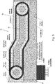
- FIG. 1 shows a hot-forming line 1 according to the invention.
- steel blanks 2 are first provided, which are transferred to a continuous furnace 3 .
- an area of homogeneous intermediate cooling 4 can take place, followed by two tempering stations 5, 6 and a hot forming and press-hardening tool 7.
- a hot-formed and press-hardened component 8 is then removed from the hot-forming and press-hardening tool 7.
- a steel blank 2 is first placed in the continuous furnace 3 and is then heated to a temperature of preferably 500 to 600.degree. Either tempering to above the austenitization temperature is first carried out in the continuous furnace 3 in order to bring about homogenization of the steel material and/or thorough alloying with a pre-coating. In this case, homogeneous intermediate cooling 4 takes place in one area.
- the steel blank 2 When it is removed from the continuous furnace 3, the steel blank 2 then has a temperature of preferably between 500 and 600.degree. It is then transferred to a first temperature control station 5, followed by a second temperature control station 6. In each temperature control station 5, 6, at least partial heating takes place via a temperature delta per temperature control station of less than 300° C., in particular less than 250° C., preferably less than 200° C.
- the steel blank 2 then has a temperature of preferably 750 to 775° C. in or after the first tempering station 5 .
- the steel blank 2 has at least partially a temperature of greater than AC3, and therefore greater than 900° C., in particular greater than 920° C.
- the blank that has been partially tempered in this way is transferred to a hot-forming and press-hardening tool 7, hot-formed and press-hardened here.
- a second multiple-hearth furnace 9 can be arranged in the lower line in relation to the plane of the image, which can also be designed as an intermediate buffer.
- a respective contact heating then takes place, analogous to that described above from approximately 500 to 600° C. in at least two steps to a temperature partially greater than the AC3 temperature.
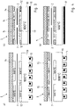
- FIGs 3a and b show a longitudinal section and a cross section of a temperature control station 5, 6 according to the invention.
- a lower temperature control plate 10 is shown, with a heating conductor 11 being arranged below the temperature control plate 10.
- the heating conductor 11 can also be integrated into the tempering plate 10 itself.
- the tempering plate 10 then has protruding extensions 12, which represent an extension of the tempering plate 10 itself and, in the closed state, partially contact a steel plate 2 arranged between them and thus partially temper it due to heat conduction.
- the cross-section according to Figure 3b shows that two steel blanks 2 can be arranged in a temperature control station 5, 6 at the same time.
- An insulating material 13 can be arranged between the individual extensions 12 .
- an insulating counter plate 14 is shown, for example in the form of a second tempering plate.
- passive heating plates 15 are themselves in turn passive heating plates 15 arranged, which according to the permanent operation a temperature of Have heat conduction via the metal plate 2, but do not have to be actively heated.
- Figure 4a and b show in principle an analogous design variant figure 3 .
- figure 3 is different figure 3 given the possibility in longitudinal section to temper a steel plate 2 with different wall thicknesses over the longitudinal course.
- the upper heating plates 15 are designed with a different surface profile, which adapts to the different wall thicknesses of the steel blanks.
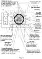
- figure 5 shows a cross section through a temperature control plate 10 with an integrated heating conductor 11. This is arranged in the base body of the temperature control plate 10 and then filled with a casting compound, so that a heating conductor 11 is fixed in the base body.
- the figure 6 tempering effect shown are exerted.
- a primary flow of heat is generated by the heating conductor 11 itself and given off to the tempering plate 10 .
- a secondary heat flow is generated decentrally within the tempering plate 10 itself due to the intensity of the heat flow and in turn is then released here to individual printed circuit boards 2 .
- inductive temperature control can also take place here on a steel plate 2 to be heated.
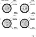
- Figure 7a to d show different cross-sectional shapes of a heating conductor 11.
- the heating conductor 11 is arranged as a sheathed heating conductor in the tempering plate 10 itself. This has a cladding tube, an electrical insulation and a heating conductor 11 arranged therein itself.
- the heating conductor 11 can be produced as a solid heating conductor, in the form of several heating conductors or also as a hollow heating conductor.
- the heating conductor 11 itself is then supplied with an electric current and then heats up, in particular according to the principle shown in figure 6 .
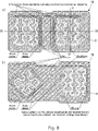
- Figure 8a and b show a respective top view of a temperature control plate 10 according to the invention. It is shown that the respective heating conductor 11 is arranged in a running groove. This groove can, for example, extend only partially over the respective surface of the temperature control plate 10 according to the principle of a meander, ie in a meandering or serpentine manner. Thus, the in Figures 3a to 4b The partial areas shown, each with 930° C., are formed as part of a longitudinal section. A longitudinal section line is shown according to III-III in Figure 8a . If the heating conductor 11 is arranged in the tempering plate 10, it is fixed in position with a casting compound. The heating conductor 11 can then be passed through the base body of the tempering plate 10 through the openings shown on a respective rear side 17 and electrically connected (not shown in more detail).
- Fig. 12 shows a cross-section along line IX-IX Figure 8a a temperature control plate 10.
- the heating conductor 11 is arranged in the temperature control plate 10.
- the surface 16 of the tempering plate 10 itself has a jump in thickness, so that so-called tailored blanks or patched, that is, partially double-layered steel blanks with different wall thicknesses can be processed as steel blanks 2.
- a corresponding conductor end is shown on a rear side 17 in order to electrically connect the heating conductor 11 present in the tempering plate 10, not shown in detail, to an energy source.
Landscapes
- Engineering & Computer Science (AREA)
- Chemical & Material Sciences (AREA)
- Mechanical Engineering (AREA)
- Physics & Mathematics (AREA)
- Thermal Sciences (AREA)
- Materials Engineering (AREA)
- Crystallography & Structural Chemistry (AREA)
- Metallurgy (AREA)
- Organic Chemistry (AREA)
- General Engineering & Computer Science (AREA)
- Combustion & Propulsion (AREA)
- Electromagnetism (AREA)
- Heat Treatment Of Articles (AREA)
- Heat Treatment Of Strip Materials And Filament Materials (AREA)
- Control Of Heat Treatment Processes (AREA)
Abstract
Description
- Die vorliegende Erfindung betrifft ein Verfahren zum Erwärmen einer Stahlplatine gemäß den Merkmalen im Oberbegriff von Anspruch 1.
- Die vorliegende Erfindung betrifft eine Temperierstation zum Einsatz in einem Warmumform- und Presshärteprozess gemäß den Merkmalen im Oberbegriff von Anspruch 8.
- Aus dem Stand der Technik ist es bekannt, insbesondere zur Herstellung von Automobilbauteilen die sogenannte Warmumform- und Presshärtetechnologie anzuwenden. Hierbei werden härtbare Stahllegierungen eingesetzt, beispielsweise Bormanganstahl, welche über eine Temperatur zumindest partiell oberhalb der Austenitisierungstemperatur erwärmt werden. Die Austenitisierungstemperatur wird auch AC3 Temperatur genannt und beträgt je nach Stahlsorte über 900° C.
- Eine so erwärmte Platine wird im Anschluss im warmen Zustand in eine Presse transferiert und dann annähernd bei AC3 Temperatur umgeformt und unmittelbar im Anschluss danach derart rasch abgekühlt bzw. abgeschreckt, dass eine Gefügeumwandlung stattfindet und sich ein gehärtetes Gefüge einstellt.
- Entsprechende Herstellungsverfahren sind beispielsweise aus der
EP 2 907 881 B1 , aus derEP 3 530 760 A1 sowie derEP 3 276 012 A1 bekannt. - Zudem wird hierbei für die Erwärmung eine sogenannte Kontakterwärmung eingesetzt. Hierbei werden Kontakttemperierstationen verwendet, um die Platine auf eine Temperatur zumindest bereichsweise größer AC3 zu erwärmen.
- Aufgrund des starken Aufheizens der Platine innerhalb kürzester Zeit von anfänglich Raumtemperatur auf über 900° C werden die Temperierstationen, konkret die eingesetzten Heizplatten aufgrund der Ausdehnungskräfte der Platine selbst (beim Erwärmen) belastet.
- Aufgabe der vorliegenden Erfindung ist es daher, ausgehend vom Stand der Technik eine Erwärmungsmöglichkeit zu schaffen, bei welcher eine jeweilige Platine partiell individuell und effektiv bei verkürzter Aufheizdauer temperiert werden kann.
- Die zuvor genannte Aufgabe wird erfindungsgemäß mit einem Verfahren zur Erwärmung einer Stahlplatine gemäß dem Merkmal im Anspruch 1 gelöst.
- Ein gegenständlicher Teil der Aufgabe wird erfindungsgemäß mit einer Temperierstation zum Einsatz in einem Warmumform- und Presshärteprozess mit den Merkmalen im Anspruch 8 gelöst.
- Erfindungsgemäß ist vorgesehen, dass als Erwärmungsstation in einer Warmformlinie mehrere Temperierstationen hintereinander angeordnet sind.
- Bevorzugt sind alle Temperierstationen als Kontakttemperierstationen ausgebildet. Es kann jedoch auch zunächst eine Erwärmung, beispielsweise homogen auf eine Temperatur stattfinden zur Durchlegierung einer metallischen Beschichtung, insbesondere einer AISi-Beschichtung als intermetallische Phase, dies kann bspw. mit einem Durchlaufofen oder Etagenofen geschehen.
- Grundsatzidee ist es jedoch, dass mindestens zwei, bevorzugt drei, insbesondere vier in Reihe hintereinander geschaltete Temperierstationen eine stufenweise Erwärmung durchführen mit einem jeweiligen Temperaturdelta von weniger als 300° C, insbesondere weniger als 250° C, ganz besonders bevorzugt weniger als 200° C.
- Durch die einzelnen Erwärmungsschritte werden unter anderem zwei wesentliche Vorteile erreicht. Zum einen wird die Zeit verkürzt, in welcher pro Station die Temperatur erhöht wird. Es muss somit nicht beispielsweise in nur einer Station von Umgebungstemperatur auf über 900° C erwärmt werden. Hingegen muss pro Temperierstation ein Temperaturdelta von weniger als 300° C überwunden werden.
- Die Zeit, die hierfür pro Station benötigt wird, ist somit kürzer. Mehrere hintereinander geschaltete Stationen können somit in einer kürzeren Taktzeit jeweils die Platinen erwärmen. Insgesamt kann somit die Taktzeit auf mehrere Temperierstationen aufgeteilt werden und dadurch bedingt absolut gesehen, verringert werden. Insbesondere können Taktzeiten kleiner 20 Sekunden zur Temperierung pro Temperierstation realisiert werden.
- Ein zweiter wesentlicher Vorteil ist, dass ein nur geringeres Temperaturdelta pro Temperierstation eingestellt wird und somit die thermische Dehnung pro Temperierstation, insbesondere eine zu temperierende Platine kontaktierende Werkzeugkomponenten aufgrund der erreichten Temperaturunterschiede in jeder Temperierstation möglichst geringgehalten sind.
- Hierdurch kann insbesondere ein optimaler Temperaturübergang bei Kontakterwärmung realisiert werden, da sich der voreingestellte Anpressdruck über den Erwärmungszeitraum aufgrund von geringen Temperaturdehnungen unwesentlich verändert. Ein optimal eingestellter Anpressdruck pro Temperierstation ist jedoch notwendig, da somit gewährleistet ist, dass während der Zeit der Kontakterwärmung ein optimaler Wärmeübergang von Temperierplatte der Temperierstation an die zu erwärmende Platine stattfindet.
- Im Sinne der Erfindung ist es jedoch auch möglich, eine Vorerwärmungsstation bereitzustellen. Beispielsweise kann somit auf 500° C bis 650° C vorerwärmt werden bzw. ein davor geschaltetes Durchlegieren einer Vorbeschichtung, z. B. AlSi-Vorbeschichtung, mit der Platine erreicht werden und dann das Vorerwärmen auf ca. 500° C zunächst als Zwischenkühlen stattfindet. Dies erfolgt besonders bevorzugt auf ca. 550 bis 650° C. Das Vorerwärmen kann auf eine Ausgangstemperatur von 500° C bis 650° C in einem Ofen erfolgen.
- Im Fall von vorbeschichteten Platinen, wie z. B AISi-Beschichtung, kann die Platine zunächst austenitisiert werden und dabei mit dem Stahlgrundmaterial unter Bildung von intermetallischen Phasen durchlegiert werden, und anschließend im selben Ofen oder einem nachgelagerten Transfer an oder mit Luft abgekühlt werden auf die genannte Vorwärmtemperatur von ca. 500° C bis 650° C.
- Dies kann beispielsweise in einem Durchlaufofen oder auch in einem Etagenofen stattfinden. Im Anschluss daran folgen dann mindestens zwei Temperierstationen, welche beispielsweise von 600° C auf 775° C erwärmt sowie eine zweite Temperierstation, die von 750 bis 775° C auf größer gleich 900° C erwärmt. Mithin pro Temperierstation ein Temperaturdelta von weniger als 300° C, insbesondere weniger als 250° C, ganz besonders bevorzugt, weniger als 200° C überwunden wird, so dass mit der jeweiligen Kontakterwärmung eine nur geringe thermische Ausdehnung der Platine in der jeweiligen Temperierstation hervorgeht und somit ein optimal voreingestellter Anpressdruck ausgenutzt werden kann.
- Eine jeweilige Temperierstation kann im Sinne der Erfindung beispielsweise durch zwei auf gegenüberliegenden Seiten angeordneten Temperierplatten ausgebildet sein. Beide Temperierplatten können aktiv geheizt sein. Es kann jedoch auch nur eine Temperierplatte aktiv geheizt sein, wohingegen die andere Temperierplatte entweder als isolierte Gegenlage oder als passiver Gegenhalter angeordnet ist.
- Insbesondere bei partieller Temperierung können einzelne Bereiche der jeweiligen Temperierplatte geheizt sein. Es können auch Bereiche derart ausgespart sein, dass kein Anlagenkontakt stattfindet und/oder dass in Bereichen, die nicht erwärmt werden sollen, Isolierwerkstoff oder Kühlmittel angeordnet sind.
- Ein weiterer Aspekt der Erfindung sieht vor, dass die Temperierplatte selbst einen zugeordneten Heizleiter aufweist. Der Heizleiter ist insbesondere in der Temperierplatte selbst eingebracht. Besonders bevorzugt ist hierzu die Temperierplatte aus nicht magnetischem Werkstoff bzw. amagnetischem Werkstoff hergestellt. Es kann jedoch auch eine Temperierplatte aus magnetischem Werkstoff verwendet werden. Der Heizleiter erwärmt die Temperierplatte selbst. Diese Erwärmung kann sowohl aufgrund von Wärmeleitung des Heizleiters selbst erfolgen, jedoch auch induktiv. Dies bedeutet, dass der Heizleiter die Temperierplatte selbst aufgrund seiner Eigenerwärmung und Wärmeleitung vom Heizleiter an die Temperierplatte erwärmt. Optional ergänzend kann der Heizleiter selbst auch die Temperierplatte induktiv, das heißt, mittels induzierter Wirbelstromverluste, erwärmen. Die Temperierplatte selbst erwärmt dann die Platine aufgrund von Wärmeleitung von Temperierplatte an die Platine.
- Wiederum optional ergänzend kann erfindungsgemäß auch vorgesehen sein, dass der Heizleiter selbst auch die Platine induktiv erwärmt. Dies bedeutet, dass der Heizleiter während des Kontaktvorganges bestromt ist und somit aufgrund seines elektrischen Feldes eine induktive Erwärmung auch der Platine vornehmen kann.
- Somit betrifft die vorliegende Erfindung ein Verfahren zum Anwenden dieser Erwärmungstechnologie, zugleich jedoch auch eine Temperierstation, wobei in einer Temperierplatte ein Heizleiter angeordnet ist und erfindungsgemäß der Heizleiter die Temperierplatte erwärmt und zusätzlich induktiv die Platine erwärmt.
- Die Temperierplatte wird nachfolgend auch als Grundkörper bezeichnet.
- Um den Grundkörper konduktiv und induktiv zu beheizen, muss die darin eingebettete Mantel-Heizleiter-Schleife gespeist werden mit einer elektrischen Wechselspannung, vorzugsweise mit einer Wechselspannung im Bereich der Mittelfrequenz von 0,5kHz bis 50kHz.
- Aufgrund der unvollständigen Schirmung der mit einer elektrischen Wechselspannung gespeisten Mantel-Heizleiter-Schleife streut das magnetische Wechselfeld in die zu erwärmenden Bereiche der Platine aus Stahl und bewirkt auch bewirkt auch dort neben der Temperaturerhöhung durch Wärmeleitung und Wärmestrahlung eine Temperaturerhöhung durch induktive generierte elektrische Wirbelstromstärken.
- Durch das Anordnen von wenigstens 3 Mantel-Heizleiter-Schleifen zu einem Induktor lässt sich ein magnetisches Wanderfeld von einer sich ändernden Intensität und Frequenz bzw. Geschwindigkeit erzeugen, welches das Metallgefüge oder deren Körner wälzt (Kneten, Rühren) oder mahlt (Reiben, Rütteln), und somit die Temperatur der erwärmenden Bereiche der Platine durch innere Reibung gleichmäßig steigert.
- Es besteht ebenfalls vorhandene Möglichkeit den beheizbaren Grundkörper und/oder die Platine mittels der Induktion über das Temperatur-Niveau des elektrischen Heizleiters hinaus zu erwärmen.
- Grund dessen, dass Felder im Allgemeinen sich nicht begrenzen, sondern nur dämpfen lassen, wird eine sich in dem Außenraum des Grundkörpers befindende Platine von einem magnetischen Streufeld durchsetzt. Falls die von dem magnetischen Streufeld in der Platine induzierte Spannung eine elektrische Wirbelstromstärke treibt, welche die Wärme mit einer größeren thermischen Leistung in einem Bereich der Platine erzeugt als dieser Bereich der Platine an die Umgebung abgeben kann, wird dieser Bereich induktiv erwärmt, auch wenn die Platine nicht elektrisch oder stofflich an den Grundkörper geschlossen ist.
- Somit ist ein zu erwärmender Bereich einer Platine vorzugsweise in einem kleinstmöglichen Abstand zu einem sich annähernd parallel zu diesem Bereich erstreckenden und mit einer elektrischen Wechselspannung gespeisten Mantelheizleiter anzuordnen. Konkret haben sich Abstände zwischen Platinenoberfläche und Mantelheizleiter von 2 mm bis 50 mm und/oder Abstände zweier Mantelheizleiter zueinander zwischen 5 mm und 100 mm als wirksam erwiesen für eine ausreichend homogene zusätzliche induktive Wärmeeinkoppelung.
- Weitere Merkmale, Eigenschaften und Aspekte der Erfindung sind in den nachfolgenden Figuren dargestellt. Bevorzugte Ausgestaltungsvarianten werden in schematischen Figuren erläutert. Diese dienen dem einfachen Verständnis der Erfindung. Es zeigen
- Figur 1
- eine erfindungsgemäße Warmformlinie zum Temperieren einer Stahlplatine mit einem Durchlaufofen,
- Figur 2
- eine alternative Ausgestaltung mit einem Etagenofen,
- Figur 3
- eine Querschnittsansicht,
- Figur 4a und b eine
- Längsansicht und Querschnittsansicht einer erfindungsgemäßen Temperierstation und
- Figur 5 ff.
- verschiedene Ansichten von Heiztemperierplatten mit Heizleitern.
- In den Figuren werden für gleiche oder ähnliche Bauteile dieselben Bezugszeichen verwendet, auch wenn eine wiederholte Beschreibung aus Vereinfachungsgründen entfällt.
-
Figur 1 zeigt eine erfindungsgemäße Warmformlinie 1. Hierbei werden zunächst Stahlplatinen 2 bereitgestellt, die in einen Durchlaufofen 3 überführt werden. Am Ende des Durchlaufofens 3 kann ein Bereich einer homogenen Zwischenkühlung 4 stattfinden, gefolgt von zwei Temperierstationen 5, 6 und einem Warmumform- und Presshärtewerkzeug 7. Im Anschluss daran wird ein warmumgeformtes und pressgehärtetes Bauteil 8 aus dem Warmumform- und Presshärtewerkzeug 7 entnommen. - In dem Durchlaufofen 3 wird zunächst eine Stahlplatine 2 eingelegt, welche dann auf eine Temperatur von bevorzugt 500 bis 600° C erwärmt wird. Entweder wird in dem Durchlaufofen 3 zunächst eine Temperierung auf über Austenitisierungstemperatur durchgeführt, um eine Homogenisierung des Stahlmaterials und/oder ein Durchlegieren mit einer Vorbeschichtung herbeizuführen. In diesem Fall findet in einem Bereich eine homogene Zwischenkühlung 4 statt. Bei Entnahme aus dem Durchlaufofen 3 weist dann die Stahlplatine 2 eine Temperatur zwischen bevorzugt 500 bis 600° C auf. Sie wird dann in eine erste Temperierstation 5, gefolgt von einer zweiten Temperierstation 6 überführt. In jeder Temperierstation 5, 6 findet zumindest partiell eine Erwärmung statt über ein Temperaturdelta pro Temperierstation von weniger als 300° C, insbesondere weniger als 250° C, bevorzugt weniger als 200° C statt.
- Die Stahlplatine 2 weist dann in bzw. nach der ersten Temperierstation 5 eine Temperatur von bevorzugt 750 bis 775° C auf. Nach der zweiten Temperierstation 6 weist die Stahlplatine 2 zumindest partiell eine Temperatur von größer AC3, mithin größer als 900° C, insbesondere größer als 920° C auf. Im Anschluss daran wird die so partiell temperierte Platine in ein Warmumform- und Presshärtewerkzeug 7 überführt, hier warmgeformt und pressgehärtet.
- In
Figur 2 wird die Stahlplatine 2 in einen Etagenofen 9 eingelegt. Alternativ kann ein zweiter Etagenofen 9 auf die Bildebene bezogen in der unteren Linie dargestellt angeordnet sein, welche auch als Zwischenpuffer ausgelegt werden kann. In einer jeweils ersten und zweiten Temperierstation 5, 6 findet dann eine jeweilige Kontakterwärmung statt, analog wie oben beschrieben von ca. 500 bis 600° C in mindestens zwei Schritten auf eine Temperatur partiell größer als AC3 Temperatur. - Insgesamt können somit auch in
Figur 1 , Taktzeiten von unter 30 Sekunden, insbesondere unter 20 Sekunden, pro Temperierstation 5, 6 und somit auf den Gesamtprozess erreicht werden. Im Falle des Ausführungsbeispiels vonFigur 2 ist es auch vorstellbar, dass das Warmumform- und Presshärtewerkzeug 7 aus zwei Erwärmungslinien beliefert wird und somit aus der oberen oder unteren Erwärmungslinie bestückt werden kann. -
Figuren 3a und b zeigen einen Längs- und einen Querschnitt einer erfindungsgemäßen Temperierstation 5, 6. Dargestellt ist eine untere Temperierplatte 10, wobei unterhalb der Temperierplatte 10 ein Heizleiter 11 angeordnet ist. Der Heizleiter 11 kann auch in die Temperierplatte 10 selbst integriert sein. Die Temperierplatte 10 weist dann überstehende Fortsätze 12 auf, die eine Verlängerung der Temperierplatte 10 selbst darstellten und im geschlossenen Zustand eine dazwischen angeordnete Stahlplatine 2 partiell kontaktieren und somit partiell temperieren, aufgrund von Wärmeleitungen. Der Querschnitt gemäßFigur 3b zeigt, dass zwei Stahlplatinen 2 gleichzeitig in einer Temperierstation 5, 6 angeordnet werden können. Zwischen den einzelnen Fortsätzen 12 kann ein Isoliermaterial 13 angeordnet sein. Auf der gegenüberliegenden Seite ist eine Isoliergegenplatte 14 dargestellt, beispielsweise in Form einer zweiten Temperierplatte. Hierin sind selbst wiederum passive Heizplatten 15 angeordnet, welche durch den dauerhaften Betrieb entsprechend eine Temperatur von Wärmeleitung über die Metallplatine 2 aufweisen, jedoch nicht selbst aktiv geheizt werden müssen. -
Figur 4a und b zeigen prinzipiell eine analoge Ausgestaltungsvariante zuFigur 3 . Hier ist jedoch im Unterschied zuFigur 3 im Längsschnitt die Möglichkeit gegeben, eine Stahlplatine 2 mit voneinander verschiedenen Wandstärken über deren Längsverlauf zu temperieren. Hierzu sind die oberen Heizplatten 15 mit einem verschiedenen Oberflächenprofil ausgebildet, das sich an den unterschiedlichen Wandstärken der Stahlplatinen anpasst. -
Figur 5 zeigt einen Querschnitt durch eine Temperierplatte 10 mit integriertem Heizleiter 11. Dieser ist im Grundkörper der Temperierplatte 10 angeordnet und dann mit einer Gussmasse ausgegossen, so dass ein Heizleiter 11 in dem Grundkörper fixiert ist. Erfindungsgemäß kann der damit inFigur 6 dargestellte Temperierungseffekt ausübt werden. Zunächst wird ein primärer Wärmestrom durch den Heizleiter 11 selbst erzeugt und an die Temperierplatte 10 abgegeben. Ein sekundärer Wärmestrom wird aufgrund der Wärmestromstärke dezentral innerhalb der Temperierplatte 10 selbst erzeugt und wiederum hier dann an einzelne ergangene Platine 2 abgegeben. Es erfolgt ein tertiärer Wärmestrom aus der Überlagerung von primärem Wärmestrom und sekundärem Wärmestrom an den Außenflächen der Temperierplatte 10. Ergänzt nicht näher dargestellt, kann aufgrund insbesondere des magnetischen Wechselflusses jedoch an einer zu erwärmenden Stahlplatine 2 ebenfalls auch hier eine induktive Temperierung stattfinden. -
Figur 7a bis d zeigen voneinander verschiedene Querschnittsformen eines Heizleiters 11. Der Heizleiter 11 wird jeweils als Mantelheizleiter in der Temperierplatte 10 selbst angeordnet. Dieser weist ein Hüllrohr, eine elektrische Isolierung und ein darin angeordneter Heizleiter 11 selber. Der Heizleiter 11 kann als Massivheizleiter, in Form von mehreren Heizleitern oder auch als jeweils hohler Heizleiter hergestellt werden. Der Heizleiter 11 selbst wird dann mit einem elektrischen Strom beaufschlagt und erwärmt sich dann insbesondere nach dem Prinzip dargestellt inFigur 6 . -
Figur 8a und b zeigen eine jeweilige Draufsicht auf eine erfindungsgemäße Temperierplatte 10. Dargestellt ist, dass der jeweilige Heizleiter 11 in einer verlaufenden Nut angeordnet wird. Diese Nut kann sich beispielsweise nach dem Prinzip eines Mäanders, mithin mäanderförmig bzw. schlangenlinienförmig nur partiell über die jeweilige Fläche der Temperierplatte 10 erstrecken. Somit können die inFiguren 3a bis 4b dargestellten partiellen Bereiche mit jeweils 930° C im Rahmen eines Längsschnittes ausgebildet werden. Eine Längsschnittlinie ist dargestellt gemäß III-III inFigur 8a . Ist der Heizleiter 11 in der Temperierplatte 10 angeordnet, wird dieser mit einer Gussmasse lagefixiert. Der Heizleiter 11 kann dann durch dargestellte Öffnungen auf einer jeweiligen Rückseite 17 durch den Grundkörper der Temperierplatte 10 durchgeführt werden und elektrisch nicht näher dargestellt, angeschlossen werden. -
Figur 9 zeigt einen Querschnitt entlang der Schnittlinie IX-IX ausFigur 8a einer Temperierplatte 10. Hier ist der Heizleiter 11 in der Temperierplatte 10 angeordnet. Die Oberfläche 16 der Temperierplatte 10 selber weist einen Dickensprung auf, so dass sogenannte tailored blanks oder gepatchte, das heißt, abschnittsweise doppellagige Stahlplatinen mit unterschiedlichen Wandstärken als Stahlplatinen 2 verarbeitet werden können. - Dargestellt ist auf einer Rückseite 17 ein entsprechendes Leiterende, um den in der Temperierplatte 10 vorhandenen Heizleiter 11, nicht näher dargestellt, elektrisch mit einer Energiequelle zu verbinden.
-
- 1 -
- Warmformlinie
- 2 -
- Stahlplatine
- 3 -
- Durchlaufofen
- 4 -
- homogene Zwischenkühlung
- 5 -
- Temperierstation
- 6 -
- Temperierstation
- 7 -
- Warmumform- und Presshärtewerkzeug
- 8 -
- Bauteil
- 9 -
- Etagenofen
- 10-
- Temperierplatte
- 11 -
- Heizleiter
- 12 -
- Fortsatz
- 13 -
- Isoliermaterial
- 14 -
- Isoliergegenplatte
- 15 -
- Heizplatte
- 16 -
- Oberfläche
- 17 -
- Rückseite
Claims (10)
- Verfahren zur Herstellung einer erwärmten Stahlplatine (2), insbesondere in ein einem Warmumform- und Presshärteprozess, wobei in Reihe hintereinander verschiedene Temperierstationen (5, 6) angeordnet sind, um die Stahlplatine (2) stufenweise auf zumindest partiell eine Temperatur größer gleich AC3 zu erwärmen, dadurch gekennzeichnet, dass pro Temperierstation (5, 6) eine Erwärmung um ein Temperaturdelta von weniger als 300° C stattfindet.
- Verfahren nach Anspruch 1, dadurch gekennzeichnet, dass mindestens drei, insbesondere vier Temperierstationen (5, 6) hintereinander angeordnet sind.
- Verfahren nach Anspruch 1 oder 2, dadurch gekennzeichnet, dass die Temperierstationen (5, 6) mittels Kontakterwärmung betrieben werden, insbesondere durch den Einsatz von Temperierplatten (10).
- Verfahren nach einem der vorangegangenen Ansprüche, dadurch gekennzeichnet, dass die Stahlplatinen (2) mittels eines Transfersystems zwischen den Temperierstationen (5, 6) transportiert werden oder dass zwischen den Temperierstationen (5, 6) ein Manipulator angeordnet ist.
- Verfahren nach einem der vorangegangenen Ansprüche, dadurch gekennzeichnet, dass die Stahlplatine (2) in einer ersten Temperierstation (5) zumindest abschnittsweise mit einer Heizrate von 15 bis 50 K/s erwärmt wird und in einer letzten Temperierstation (6) vor dem Warmumform- und Presshärteprozess mit einer Heizrate von 5 bis 15 K/s erwärmt wird.
- Verfahren nach einem der vorangegangenen Ansprüche, dadurch gekennzeichnet, dass die Stahlplatine (2) durch eine Temperierplatte (10) erwärmt wird und zusätzlich induktiv durch ein Heizmittel erwärmt wird, insbesondere durch einen der Temperierplatte (10) zugeordneten Heizleiter (11).
- Verfahren nach einem der vorangegangenen Ansprüche, dadurch gekennzeichnet, dass beim Schließen der Temperierstation (5, 6) ein Anpressdruck auf die zu erwärmende Stahlplatine (2) aufgebracht wird.
- Temperierstation zum Einsatz in einem Warmumform- und Presshärteprozess, aufweisend mindestens eine Temperierplatte (10), zur zumindest abschnittsweisen Temperierung einer Stahlplatine (2), wobei in der Temperierplatte (10) ein Heizleiter (11) angeordnet ist, dadurch gekennzeichnet, dass der Heizleiter (11) die Temperierplatte (10) erwärmt und zusätzlich induktiv die Stahlplatine (2) erwärmt.
- Temperierstation nach Anspruch 8, dadurch gekennzeichnet, dass eine zweite Temperierplatte (10) als Gegenhalter auf der gegenüberliegenden Seite der Stahlplatine (2) vorhanden ist, wobei die zweite Temperierplatte (10) bevorzugt auch zumindest partiell aktiv beheizbar ist.
- Temperierstation nach Anspruch 8 oder 9, dadurch gekennzeichnet, dass die Temperierplatte (10) aus nicht magnetischem Werkstoff ausgebildet ist.
Applications Claiming Priority (1)
| Application Number | Priority Date | Filing Date | Title |
|---|---|---|---|
| DE102020127057.7A DE102020127057A1 (de) | 2020-10-14 | 2020-10-14 | Verfahren zur Herstellung einer Stahlplatine sowie Temperierstation |
Publications (2)
| Publication Number | Publication Date |
|---|---|
| EP3985133A2 true EP3985133A2 (de) | 2022-04-20 |
| EP3985133A3 EP3985133A3 (de) | 2022-06-15 |
Family
ID=77499705
Family Applications (1)
| Application Number | Title | Priority Date | Filing Date |
|---|---|---|---|
| EP21193005.2A Pending EP3985133A3 (de) | 2020-10-14 | 2021-08-25 | Verfahren zur herstellung einer stahlplatine sowie temperierstation |
Country Status (4)
| Country | Link |
|---|---|
| US (1) | US20220112568A1 (de) |
| EP (1) | EP3985133A3 (de) |
| CN (1) | CN114350901A (de) |
| DE (1) | DE102020127057A1 (de) |
Citations (4)
| Publication number | Priority date | Publication date | Assignee | Title |
|---|---|---|---|---|
| WO2016012442A1 (de) | 2014-07-23 | 2016-01-28 | Voestalpine Stahl Gmbh | Verfahren zum aufheizen von stahlblechen und vorrichtung zur durchführung des verfahrens |
| EP3276012A1 (de) | 2016-07-29 | 2018-01-31 | Benteler Automobiltechnik GmbH | Temperierstation mit mantelheizleiter |
| EP2907881B1 (de) | 2014-02-07 | 2019-04-24 | Benteler Automobiltechnik GmbH | Warmformlinie und Verfahren zur Herstellung von warmumgeformten Blechprodukten |
| EP3530760A1 (de) | 2018-02-23 | 2019-08-28 | Benteler Automobiltechnik GmbH | Verfahren zum herstellen eines warmumgeformten und gehärteten stahlblechbauteils |
Family Cites Families (17)
| Publication number | Priority date | Publication date | Assignee | Title |
|---|---|---|---|---|
| US3889912A (en) * | 1974-02-01 | 1975-06-17 | Robert G Ray | Curtain rod and window shade bracket |
| US6781100B2 (en) * | 2001-06-26 | 2004-08-24 | Husky Injection Molding Systems, Ltd. | Method for inductive and resistive heating of an object |
| TWI254598B (en) * | 2001-06-26 | 2006-05-01 | Husky Injection Molding | Apparatus for inductive and resistive heating of an object |
| US6717118B2 (en) * | 2001-06-26 | 2004-04-06 | Husky Injection Molding Systems, Ltd | Apparatus for inductive and resistive heating of an object |
| US7034263B2 (en) * | 2003-07-02 | 2006-04-25 | Itherm Technologies, Lp | Apparatus and method for inductive heating |
| FR2887739B1 (fr) * | 2005-06-22 | 2007-08-31 | Roctool Soc Par Actions Simpli | Dispositif de chauffage par induction et procede de fabrication de pieces a l'aide d'un tel dispositif |
| JP2011255413A (ja) * | 2010-06-11 | 2011-12-22 | Toyoda Iron Works Co Ltd | 鋼板の加熱装置、プレス成形品の製造方法、およびプレス成形品 |
| DE102012110650C5 (de) * | 2012-11-07 | 2017-12-14 | Benteler Automobiltechnik Gmbh | Warmformlinie zur Herstellung warmumgeformter und pressgehärteter Stahlblechprodukte |
| EP2905346B1 (de) * | 2014-01-23 | 2020-09-02 | Schwartz GmbH | Wärmebehandlungsverfahren |
| KR20160035627A (ko) * | 2014-09-23 | 2016-04-01 | 주식회사 웰탑테크노스 | 초고장력 강판 열처리 시스템 |
| DE102016120605A1 (de) * | 2016-10-27 | 2018-05-03 | Schwartz Gmbh | Verfahren und Vorrichtung zur Wärmebehandlung eines metallischen Bauteils |
| ES2827455T3 (es) * | 2016-02-25 | 2021-05-21 | Benteler Automobiltechnik Gmbh | Método de fabricación de un componente de automóvil con al menos dos zonas de resistencia mutuamente diferentes |
| DE102017109613B3 (de) * | 2017-05-04 | 2018-03-01 | Benteler Automobiltechnik Gmbh | Warmformlinie mit Temperierstation sowie Verfahren zum Betreiben |
| CN107186029A (zh) * | 2017-06-22 | 2017-09-22 | 苏州普热斯勒先进成型技术有限公司 | 一种可生产分区强度热冲压件的加热装置、生产线和方法 |
| DE102017115755A1 (de) * | 2017-07-13 | 2019-01-17 | Schwartz Gmbh | Verfahren und Vorrichtung zur Wärmebehandlung eines metallischen Bauteils |
| DE102017120128A1 (de) * | 2017-09-01 | 2019-03-07 | Schwartz Gmbh | Verfahren zum Erwärmen eines metallischen Bauteils auf eine Zieltemperatur und entsprechender Rollenherdofen |
| DE102017223252A1 (de) * | 2017-12-19 | 2019-06-19 | Volkswagen Aktiengesellschaft | Pressenanordnung sowie Verfahren zur Herstellung eines warmumgeformten und pressgehärteten Stahlblechteils |
-
2020
- 2020-10-14 DE DE102020127057.7A patent/DE102020127057A1/de active Pending
-
2021
- 2021-08-25 EP EP21193005.2A patent/EP3985133A3/de active Pending
- 2021-10-09 CN CN202111179357.7A patent/CN114350901A/zh active Pending
- 2021-10-13 US US17/450,727 patent/US20220112568A1/en not_active Abandoned
Patent Citations (5)
| Publication number | Priority date | Publication date | Assignee | Title |
|---|---|---|---|---|
| EP2907881B1 (de) | 2014-02-07 | 2019-04-24 | Benteler Automobiltechnik GmbH | Warmformlinie und Verfahren zur Herstellung von warmumgeformten Blechprodukten |
| WO2016012442A1 (de) | 2014-07-23 | 2016-01-28 | Voestalpine Stahl Gmbh | Verfahren zum aufheizen von stahlblechen und vorrichtung zur durchführung des verfahrens |
| DE102014110415A1 (de) | 2014-07-23 | 2016-01-28 | Voestalpine Stahl Gmbh | Verfahren zum Aufheizen von Stahlblechen und Vorrichtung zur Durchführung des Verfahrens |
| EP3276012A1 (de) | 2016-07-29 | 2018-01-31 | Benteler Automobiltechnik GmbH | Temperierstation mit mantelheizleiter |
| EP3530760A1 (de) | 2018-02-23 | 2019-08-28 | Benteler Automobiltechnik GmbH | Verfahren zum herstellen eines warmumgeformten und gehärteten stahlblechbauteils |
Non-Patent Citations (1)
| Title |
|---|
| SCHÖNHERR JULIA, POLSTER STEFAN, TRÂN RICARDO: "Kontakterwärmung", ZEITSCHRIFT FÜR WIRTSCHAFTLICHEN FABRIKBETRIEB, vol. 115, no. 9, 1 September 2020 (2020-09-01), pages 612 - 616, XP009555299, ISSN: 0947-0085, DOI: 10.1515/zwf-2020-1150915 * |
Also Published As
| Publication number | Publication date |
|---|---|
| CN114350901A (zh) | 2022-04-15 |
| DE102020127057A1 (de) | 2022-04-14 |
| EP3985133A3 (de) | 2022-06-15 |
| US20220112568A1 (en) | 2022-04-14 |
Similar Documents
| Publication | Publication Date | Title |
|---|---|---|
| EP2497840B2 (de) | Ofensystem zum partiellen Erwärmen von Stahlblechteilen | |
| EP2182081B1 (de) | Verfahren zur thermischen Behandlung eines beschichteten Stahlblechkörpers | |
| EP2907881B1 (de) | Warmformlinie und Verfahren zur Herstellung von warmumgeformten Blechprodukten | |
| DE102005032113B3 (de) | Verfahren und Vorrichtung zum Warmumformen und partiellen Härten eines Bauteils | |
| EP2182082B1 (de) | Verfahren und Vorrichtung zur Temperierung eines Stahlblechkörpers | |
| EP2864506B1 (de) | Verfahren und vorrichtung zur herstellung eines pressgehärteten metallbauteils | |
| EP2730346B2 (de) | Warmformlinie zur Herstellung warmumgeformter und pressgehärteter Stahlblechprodukte | |
| DE102012214274B4 (de) | Vordiffundierte Al-Si-Beschichtungen zur Verwendung bei einer schnellen Induktionsaufheizung von pressgehärtetem Stahl | |
| DE102011078075A1 (de) | Durch Warmbehandlungsnachbearbeitung passendgemachte Eigenschaften | |
| DE102016100648B4 (de) | Wärmebehandlungsofen sowie Verfahren zur Wärmebehandlung einer vorbeschichteten Stahlblechplatine und Verfahren zur Herstellung eines Kraftfahrzeugbauteils | |
| EP2411548A1 (de) | Verfahren zum herstellen partiell gehärteter stahlbauteile | |
| EP3652352B1 (de) | Verfahren und vorrichtung zur wärmebehandlung eines metallischen bauteils | |
| DE102012021031A1 (de) | Verfahren und Vorrichtung zur Herstellung pressgehärteter Blechbauteile | |
| DE102017109613B3 (de) | Warmformlinie mit Temperierstation sowie Verfahren zum Betreiben | |
| DE102009060388A1 (de) | Mehrstufiges direktes Formhärten | |
| DE102014111501A1 (de) | Warmumformvorrichtung und Verfahren zum Herstellen von pressgehärteten Formbauteilen aus Stahlblech | |
| EP3530760A1 (de) | Verfahren zum herstellen eines warmumgeformten und gehärteten stahlblechbauteils | |
| WO2017129602A1 (de) | Wärmebehandlungsverfahren und wärmebehandlungsvorrichtung | |
| EP3420111B1 (de) | Verfahren zur gezielten bauteilzonenindividuellen wärmebehandlung | |
| WO2011082934A1 (de) | Verfahren und vorrichtung zum erwärmen und partiellem kühlen von werstücken in einem durchlaufofen | |
| EP2840153A2 (de) | Temperierstation mit Induktorerwärmung | |
| WO2018109034A1 (de) | Verfahren zum herstellen lokal gehärteter stahlblechbauteile | |
| EP2679692A1 (de) | Verfahren zur Herstellung eines pressgehärteten Formbauteils aus Stahlblech | |
| EP3184655A1 (de) | Wärmebehandlungsofen sowie verfahren zur wärmebehandlung einer vorbeschichteten stahlblechplatine und verfahren zur herstellung eines kraftfahrzeugbauteils | |
| DE102020127057A1 (de) | Verfahren zur Herstellung einer Stahlplatine sowie Temperierstation |
Legal Events
| Date | Code | Title | Description |
|---|---|---|---|
| PUAI | Public reference made under article 153(3) epc to a published international application that has entered the european phase |
Free format text: ORIGINAL CODE: 0009012 |
|
| STAA | Information on the status of an ep patent application or granted ep patent |
Free format text: STATUS: THE APPLICATION HAS BEEN PUBLISHED |
|
| AK | Designated contracting states |
Kind code of ref document: A2 Designated state(s): AL AT BE BG CH CY CZ DE DK EE ES FI FR GB GR HR HU IE IS IT LI LT LU LV MC MK MT NL NO PL PT RO RS SE SI SK SM TR |
|
| PUAL | Search report despatched |
Free format text: ORIGINAL CODE: 0009013 |
|
| STAA | Information on the status of an ep patent application or granted ep patent |
Free format text: STATUS: REQUEST FOR EXAMINATION WAS MADE |
|
| AK | Designated contracting states |
Kind code of ref document: A3 Designated state(s): AL AT BE BG CH CY CZ DE DK EE ES FI FR GB GR HR HU IE IS IT LI LT LU LV MC MK MT NL NO PL PT RO RS SE SI SK SM TR |
|
| RIC1 | Information provided on ipc code assigned before grant |
Ipc: H05B 6/10 20060101ALI20220512BHEP Ipc: B21D 22/02 20060101ALI20220512BHEP Ipc: F27D 99/00 20100101ALI20220512BHEP Ipc: F27B 9/06 20060101ALI20220512BHEP Ipc: H05B 6/00 20060101ALI20220512BHEP Ipc: H05B 3/00 20060101ALI20220512BHEP Ipc: C21D 9/48 20060101ALI20220512BHEP Ipc: C21D 9/46 20060101ALI20220512BHEP Ipc: C21D 9/00 20060101ALI20220512BHEP Ipc: C21D 8/00 20060101ALI20220512BHEP Ipc: C21D 1/42 20060101ALI20220512BHEP Ipc: C21D 1/34 20060101ALI20220512BHEP Ipc: C21D 1/673 20060101AFI20220512BHEP |
|
| 17P | Request for examination filed |
Effective date: 20220524 |
|
| STAA | Information on the status of an ep patent application or granted ep patent |
Free format text: STATUS: EXAMINATION IS IN PROGRESS |
|
| 17Q | First examination report despatched |
Effective date: 20240704 |
|
| TPAC | Observations filed by third parties |
Free format text: ORIGINAL CODE: EPIDOSNTIPA |