EP3984864A1 - Electric truck - Google Patents
Electric truck Download PDFInfo
- Publication number
- EP3984864A1 EP3984864A1 EP20841642.0A EP20841642A EP3984864A1 EP 3984864 A1 EP3984864 A1 EP 3984864A1 EP 20841642 A EP20841642 A EP 20841642A EP 3984864 A1 EP3984864 A1 EP 3984864A1
- Authority
- EP
- European Patent Office
- Prior art keywords
- power supply
- supply unit
- battery
- electric truck
- ladder frame
- Prior art date
- Legal status (The legal status is an assumption and is not a legal conclusion. Google has not performed a legal analysis and makes no representation as to the accuracy of the status listed.)
- Granted
Links
Images




Classifications
-
- B—PERFORMING OPERATIONS; TRANSPORTING
- B60—VEHICLES IN GENERAL
- B60K—ARRANGEMENT OR MOUNTING OF PROPULSION UNITS OR OF TRANSMISSIONS IN VEHICLES; ARRANGEMENT OR MOUNTING OF PLURAL DIVERSE PRIME-MOVERS IN VEHICLES; AUXILIARY DRIVES FOR VEHICLES; INSTRUMENTATION OR DASHBOARDS FOR VEHICLES; ARRANGEMENTS IN CONNECTION WITH COOLING, AIR INTAKE, GAS EXHAUST OR FUEL SUPPLY OF PROPULSION UNITS IN VEHICLES
- B60K1/00—Arrangement or mounting of electrical propulsion units
- B60K1/04—Arrangement or mounting of electrical propulsion units of the electric storage means for propulsion
-
- B—PERFORMING OPERATIONS; TRANSPORTING
- B62—LAND VEHICLES FOR TRAVELLING OTHERWISE THAN ON RAILS
- B62D—MOTOR VEHICLES; TRAILERS
- B62D21/00—Understructures, i.e. chassis frame on which a vehicle body may be mounted
- B62D21/02—Understructures, i.e. chassis frame on which a vehicle body may be mounted comprising longitudinally or transversely arranged frame members
-
- B—PERFORMING OPERATIONS; TRANSPORTING
- B62—LAND VEHICLES FOR TRAVELLING OTHERWISE THAN ON RAILS
- B62D—MOTOR VEHICLES; TRAILERS
- B62D21/00—Understructures, i.e. chassis frame on which a vehicle body may be mounted
- B62D21/02—Understructures, i.e. chassis frame on which a vehicle body may be mounted comprising longitudinally or transversely arranged frame members
- B62D21/03—Understructures, i.e. chassis frame on which a vehicle body may be mounted comprising longitudinally or transversely arranged frame members transverse members providing body support
-
- B—PERFORMING OPERATIONS; TRANSPORTING
- B62—LAND VEHICLES FOR TRAVELLING OTHERWISE THAN ON RAILS
- B62D—MOTOR VEHICLES; TRAILERS
- B62D21/00—Understructures, i.e. chassis frame on which a vehicle body may be mounted
- B62D21/15—Understructures, i.e. chassis frame on which a vehicle body may be mounted having impact absorbing means, e.g. a frame designed to permanently or temporarily change shape or dimension upon impact with another body
- B62D21/157—Understructures, i.e. chassis frame on which a vehicle body may be mounted having impact absorbing means, e.g. a frame designed to permanently or temporarily change shape or dimension upon impact with another body for side impacts
-
- B—PERFORMING OPERATIONS; TRANSPORTING
- B62—LAND VEHICLES FOR TRAVELLING OTHERWISE THAN ON RAILS
- B62D—MOTOR VEHICLES; TRAILERS
- B62D53/00—Tractor-trailer combinations; Road trains
- B62D53/02—Tractor-trailer combinations; Road trains comprising a uniaxle tractor unit and a uniaxle trailer unit
-
- B—PERFORMING OPERATIONS; TRANSPORTING
- B60—VEHICLES IN GENERAL
- B60K—ARRANGEMENT OR MOUNTING OF PROPULSION UNITS OR OF TRANSMISSIONS IN VEHICLES; ARRANGEMENT OR MOUNTING OF PLURAL DIVERSE PRIME-MOVERS IN VEHICLES; AUXILIARY DRIVES FOR VEHICLES; INSTRUMENTATION OR DASHBOARDS FOR VEHICLES; ARRANGEMENTS IN CONNECTION WITH COOLING, AIR INTAKE, GAS EXHAUST OR FUEL SUPPLY OF PROPULSION UNITS IN VEHICLES
- B60K1/00—Arrangement or mounting of electrical propulsion units
- B60K1/04—Arrangement or mounting of electrical propulsion units of the electric storage means for propulsion
- B60K2001/0405—Arrangement or mounting of electrical propulsion units of the electric storage means for propulsion characterised by their position
-
- B—PERFORMING OPERATIONS; TRANSPORTING
- B60—VEHICLES IN GENERAL
- B60K—ARRANGEMENT OR MOUNTING OF PROPULSION UNITS OR OF TRANSMISSIONS IN VEHICLES; ARRANGEMENT OR MOUNTING OF PLURAL DIVERSE PRIME-MOVERS IN VEHICLES; AUXILIARY DRIVES FOR VEHICLES; INSTRUMENTATION OR DASHBOARDS FOR VEHICLES; ARRANGEMENTS IN CONNECTION WITH COOLING, AIR INTAKE, GAS EXHAUST OR FUEL SUPPLY OF PROPULSION UNITS IN VEHICLES
- B60K1/00—Arrangement or mounting of electrical propulsion units
- B60K1/04—Arrangement or mounting of electrical propulsion units of the electric storage means for propulsion
- B60K2001/0405—Arrangement or mounting of electrical propulsion units of the electric storage means for propulsion characterised by their position
- B60K2001/0416—Arrangement in the rear part of the vehicle
-
- B—PERFORMING OPERATIONS; TRANSPORTING
- B60—VEHICLES IN GENERAL
- B60Y—INDEXING SCHEME RELATING TO ASPECTS CROSS-CUTTING VEHICLE TECHNOLOGY
- B60Y2200/00—Type of vehicle
- B60Y2200/10—Road Vehicles
- B60Y2200/14—Trucks; Load vehicles, Busses
-
- B—PERFORMING OPERATIONS; TRANSPORTING
- B60—VEHICLES IN GENERAL
- B60Y—INDEXING SCHEME RELATING TO ASPECTS CROSS-CUTTING VEHICLE TECHNOLOGY
- B60Y2306/00—Other features of vehicle sub-units
- B60Y2306/01—Reducing damages in case of crash, e.g. by improving battery protection
Definitions
- the present invention relates to an electric truck.
- Patent Document 1 discloses a holding structure for holding a battery pack for propulsion to a ladder frame of an electric truck.
- Patent Document 1 Japanese Patent Laid-Open No. 2016-113063
- side rails for trucks commonly have a C-shaped cross-section by having flanges provided at each edge of a web to project inward in the vehicle width direction.
- the battery when the battery is arranged in the aforementioned manner, if a side rail is deformed in a side collision, the battery does not come into surface contact with the web but receives intensive impact from the edge of a flange which comes into contact with a relatively small contact area.
- the electric truck with a battery arranged between the side rails forming a pair has a possibility of the battery becoming greatly damaged in a side collision, and thus, cannot ensure side collision safety.
- An object of the present invention is to provide an electric truck which can ensure side collision safety of a battery arranged inside the frame.
- a first aspect of the present invention is an electric truck traveling by electric power supplied from a battery, comprising a ladder frame including a pair of side rails, the side rails facing each other in vehicle width direction, and a power supply unit including the battery, the power supply unit being arranged between the side rails and connected to the side rails, wherein the side rails each have flanges having a predetermined width provided at each edge of a web, wherein the flange facing at least one of corners of the power supply device has at least one narrowed flange portion having a width smaller than the predetermined width at a location facing one of the corners of the power supply unit as viewed in the vehicle width direction.
- the ladder frame In the electric truck in which the power supply unit including the battery is connected to the side rails forming a pair, the ladder frame has increased rigidity against side impact in the region corresponding to the power supply unit. Meanwhile, the ladder frame has relatively low rigidity at the locations facing corners of the power supply unit as viewed in the vehicle width direction, and thus, when receiving impact exceeding the rigidity in a side collision, the ladder frame may be deformed in a region near a corner of the power supply unit. The side rail thus deformed may give intensive impact to the power supply unit with the edge of a flange which comes into contact with a relatively small contact area, thereby damaging the battery included in the power supply unit.
- a narrowed flange portion is provided in the flange of the ladder frame which faces a corner of the power supply unit to reduce the possibility of the side rail coming into contact with the power supply unit even when the side rail is deformed.
- the electric truck according to the first aspect of the present invention can thus ensure the side collision safety of the battery arranged inside the frame.
- a second aspect of the present invention is an electric truck according to the first aspect in which the narrowed flange portions are provided to face two vehicle front-side corners of the power supply unit, respectively.
- the narrowed flange portions are provided at the locations facing the vehicle front-side corners of the power supply unit at which the side rail is most likely to come into contact with the power supply unit when the ladder frame is deformed. The risk of the battery becoming damaged by contact between the side rail and the power supply unit is therefore reduced effectively.
- a third aspect of the present invention is an electric truck according to the first or second aspect in which the narrowed flange portions are provided to face two vehicle rear-side corners of the power supply unit, respectively.
- the narrowed flange portions are provided at the locations facing the vehicle rear-side corners of the power supply unit at which the side rail is relatively highly likely to come into contact with the power supply unit when the ladder frame is deformed. The risk of the battery becoming damaged by contact between the side rail and the power supply unit is therefore reduced effectively.
- a fourth aspect of the present invention is an electric truck according to any of the first to third aspects in which the narrowed flange portion has an arc-shaped outline.
- the narrowed flange portion provided in the flange of the side rail has an arc-shaped outline, stress concentration in the narrowed flange portion is prevented when force is applied to the frame during traveling of the vehicle.
- a fifth aspect of the present invention is an electric truck according to any of the first to fourth aspects in which the narrowed flange portion is provided such that the most narrowed point at which the narrowed flange portion has the smallest width is in alignment with the corresponding corner of the power supply unit as viewed in the vehicle width direction.
- the power supply unit is arranged with a corner facing the most narrowed point at which the narrowed flange portion has the smallest width, the risk of the power supply unit becoming damaged by contact with the ladder frame is reduced effectively.
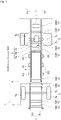
- FIG. 1 is a top view schematically showing the total structure of an electric truck 1 according to a first embodiment of the present invention.
- the electric truck 1 according to the present embodiment comprises a ladder frame 2, a cab 3, a cargo box 4, wheel mechanisms 5, a drive unit 6, a drive power supply device 7 and a power supply unit 8.
- FIG. 1 is a top view of the electric truck 1 viewed from the top of the electric truck 1 through the cab 3 and the cargo box 4.
- the ladder frame 2 comprises a left and a right side rails 2L, 2R, referred to as "a pair of side rails", and cross-members CM1 to CM8.
- the left and right side rails 2L, 2R extend in the vehicle longitudinal direction X of the electric truck 1. They are arranged parallel to each other to face each other in the vehicle width direction Y.
- the cross-members CM1 to CM8 connect the left side rail 2L to the right side rail 2R at their respective positions to form a ladder-shaped frame referred to as a "ladder frame 2".
- the ladder frame 2 supports the cab 3, the cargo box 4, the drive unit 6, the drive power supply device 7, the power supply unit 8 and other heavy objects mounted on the electric truck 1.
- the cab 3 is a structure with a driver's seat, not shown, and arranged over the front of the ladder frame 2.
- the cargo box 4 is a structure into which cargos to be transported by the electric truck 1 are loaded, and arranged over the rear of the ladder frame 2.
- the wheel mechanism 5 arranged in the front of the vehicle comprises a left and a right front wheels 5a and a front axle 5b, or shaft for the front wheels 5a, while the wheel mechanism 5 arranged in the rear of the vehicle comprises two left and two right rear wheels 5c and a rear axle 5d, or shaft for the rear wheels 5c.
- the rear wheels 5c are drive wheels to which drive power is transmitted to move the electric truck 1.
- the wheel mechanisms 5 are attached to the ladder frame 2 by means of a suspension mechanism, not shown, and support the weight of the electric truck 1.
- the drive unit 6 comprises a motor 6a, a speed reducing mechanism 6b and a differential mechanism 6c.
- the motor 6a produces drive power required to move the electric truck 1.
- the speed reducing mechanism 6b comprises a plurality of gears, not shown, to convert rotational power produced by the motor 6a into a reduced speed and transmit it to the differential mechanism 6c.
- the differential mechanism 6c distributes the power transmitted from the speed reducing mechanism 6b to the left and right rear wheels 5c.
- the drive unit 6 is configured such that drive power produced by the motor 6a is converted into a reduced rotational speed suited for moving the vehicle and transmitted to the rear axle 5d by means of the speed reducing mechanism 6b and the differential mechanism 6c.
- the drive unit 6 can thus rotate the rear wheels 5c via the rear axle 5d, thereby moving the electric truck 1.
- a front portion as viewed in the vehicle longitudinal direction X is suspended by the cross-member CM5 attached to the ladder frame 2.
- the drive power supply device 7 is an inverter. It converts DC power supplied from the power supply unit 8 into AC power and supplies it to the motor 6a, and controls the rotational speed of the motor 6a according to an accelerator operation performed in the electric truck 1.
- the power supply unit 8 comprises a battery 30 (see FIG. 3 ) which supplies electric power to the motor 6a and thus functions primarily as an energy source for moving the electric truck 1.
- the power supply unit 8 includes a plurality of battery modules BM of relatively large size and capacity (see FIG. 3 ) to store electric power required for the electric truck 1.
- the power supply unit 8 can supply electric power also to auxiliary electric devices, not shown, mounted on the electric truck 1 via a PDU 20, described later. The configuration of the power supply unit 8 will be described later in detail.
- the ladder frame 2 has a plurality of elastic supports ES to elastically support the power supply unit 8 in the vehicle width direction Y at the opposite sides.
- three elastic supports ES are provided on the outer side of the left side rail 2L and on the outer side of the right side rail 2R, each (six in total), as viewed in the vehicle width direction Y.
- the number of the elastic supports ES may however be appropriately changed depending on the weight and size of the power supply unit 8. The configuration of the elastic support ES will be described later in detail.
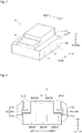
- FIG. 2 is a perspective view showing the general shape of the power supply unit 8 mounted on the electric truck 1.
- the power supply unit 8 comprises a battery housing 10, a PDU 20 and a battery 30 comprising a plurality of battery modules BM (omitted in FIG. 2 ; see FIG. 3 ).
- the battery housing 10 comprises a first battery housing portion 11 and a second battery housing portion 12 combined together, where the first and second battery housing portions are in the shape of a roughly rectangular solid and have the same length, or dimension measured in the vehicle longitudinal direction X. As viewed in the vehicle longitudinal direction X, the first battery housing portion 11 has a low-height portion in the front, in which the PDU 20 is enclosed. The battery housing 10 is thus shaped not to interfere with the cross-member CM4. Arranging the first battery housing portion 11 such that the PDU 20 enclosing portion is, between the side rails, in alignment with the cross member CM4 as viewed in the vehicle height direction Z enables effective use of space, and thus, contributes to maximizing the space to be occupied by the battery 30.
- the first battery housing portion 11 has a width, or dimension measured in the vehicle width direction Y allowing it to be located between the left and right side rails 2L, 2R. Meanwhile, the second battery housing portion 12 has a width, or dimension measured in the vehicle width direction Y equal to or greater than the width of the ladder frame 2. The second battery housing portion 12 is joined to the first battery housing portion 11 from below, as viewed in the vehicle height direction Z.
- the battery housing 10 has thus an inverted T-shaped cross-section perpendicular to the vehicle longitudinal direction X.
- the battery housing 10 is arranged such that the left and right side rails 2L, 2R extend over the steps formed due to the difference in width between the first and the second battery housing portions 11, 12. This arrangement makes it possible to secure the battery capacity by making effective use of a space between the left and right side rails 2L, 2R and a space below it.
- the battery housing 10 has a plurality of fixing regions 13 on the housing sides 12S, or outer side surfaces of the second battery housing portion 12 as viewed in the vehicle width direction Y.
- the PDU 20 is a power distribution unit which collects electric power from the battery modules BM and distributes part of the collected electric power to the auxiliary electric devices via a harness (not shown). Although in the present embodiment the PDU 20 is enclosed in the battery housing 10 with the battery 30, in some layout of components between the side rails it may be arranged outside the battery housing 10.
- FIG. 3 is a cross-sectional view showing the configuration and connecting manner of the elastic support ES for connecting the power supply unit 8 to the ladder frame 2. More specifically, FIG. 3 is a cross-sectional view showing the cross-sections of the power supply unit 8 and the elastic support ES perpendicular to the vehicle longitudinal direction X viewed from the rear of the vehicle.
- the power supply unit 8 includes a plurality of battery modules BM, where the number of the battery modules BM depends on the size of the battery housing 10.
- the shape and arrangement of the battery modules BM may be changed in various ways.
- the elastic support ES comprises a frame-side bracket ES1, an elastic connector ES2 and a battery-side bracket ES3.
- the frame-side bracket ES1 is a fixing member of metal. It is bolted to the outer side of the left or right side rail 2L, 2R as viewed in the vehicle width direction Y. As viewed in the vehicle height direction Z, the elastic connecter ES2 is connected to the frame-side bracket ES1 by means of a rubber bush on the upper side, and connected to the battery-side bracket ES3 on the lower side.
- the battery-side bracket ES3 is a fixing member of metal and fixed to the battery housing 10 in the above-mentioned fixing region 13.
- the elastic supports ES thus elastically attach the power supply unit 8 to the ladder frame 2, and even when stress is produced by twist or lateral bend of the frame during traveling of the electric truck 1, reduce the stress transmitted to the power supply unit 8 by their damping effect. The risk that that the battery 30 included in the power supply unit 8 will be damaged by the stress is therefore reduced.
- the left and right side rails 2L, 2R are elastically connected to each other by means of the elastic supports ES connected to each rail and the battery housing 10 constituting the power supply unit 8.
- the plurality of elastic supports ES thus increases the rigidity of the ladder frame 2 by connecting the side rails to each other in cooperation with the power supply unit 8, while reducing the stress applied due to twist or lateral bend of the frame.
- the plurality of elastic supports thus fulfills the same function as the cross-member.
- FIG. 4 is a top view showing the electric truck 1 with the ladder frame 2 deformed in a side collision.
- the cargo box 4 is omitted in the Figure. More specifically, FIG. 4 schematically shows the electric vehicle 1 assuming that another vehicle BC has struck the left side of the electric truck 1 in the vehicle width direction Y in the region of the power supply unit 8, so that the ladder fame 2 has been deformed.
- the electric truck 1 Since the electric truck 1 has relatively high rigidity in the region including the cab 3 and the wheel mechanism 5 including the front axle 5b and the region including the wheel mechanism 5 including the rear axle 5c, indicated as regions R1 and R5 in FIG. 4 , the electric truck 1 is not significantly deformed in these regions in a side collision. More specifically, in region R1, displacement of the ladder frame 2 is limited by frictional force produced between the left and right front wheels 5a and the road surface, and the front axle 5b and the cross-members CM1 to CM3 arranged close to each other reinforce the ladder frame 2. Thus, in region R1, deformation of the ladder frame by side impact is restricted.
- region R5 displacement of the ladder frame 2 is limited by frictional force produced between the left and right rear wheels 5c and the road surface, and the rear axle 5d and the cross-members CM5 to CM8 arranged close to each other reinforce the ladder frame 2.
- deformation of the ladder frame 2 by side impact is restricted.
- the power supply unit 8 which is connected to the left and right side rails 2L, 2R using the elastic connectors ES2, can fulfill the function of reinforcing the ladder frame like the cross-member.
- the ladder frame 2 receives side impact in the region corresponding to the power supply unit 8 indicated as region R3, deformation of the side rail in the region receiving impact is restricted.
- the ladder frame 2 has low rigidity in region R2 between the cab 3 and the elastic connectors ES2 in the front row and region R4 between the elastic connectors ES2 in the rear row and the cross-member CM5, as compared with regions R1, R3 and R5.
- the ladder frame 2 may not be able to withstand the impact and be deformed in regions R2 and R4.
- the power supply unit 8 receives intensive impact from the edge of a flange of the left or right side rail 2L, 2R on the inner side of the deformed ladder frame 2 as viewed in the vehicle width direction Y, which may cause great damage to the enclosed battery 30. Side collision safety may therefore not be able to be ensured.
- a cutout is provided in the left and right side rails 2L, 2R, as described below, to reduce the possibility of the power supply unit 8 becoming damaged by intensive impact from the side rail in a side collision.
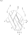
- FIG. 5 is a fragmentary enlarged view showing a part of the ladder frame 2 near a corner of the power supply unit 8. Specifically, FIG. 5 is an enlarged perspective view of the part enclosed by a dashed line in FIG. 4 , more specifically a perspective view showing a right front corner CP of the first battery housing portion 11 of the battery housing 10 constituting the power supply unit 8 and the part of the right side rail 2R facing the corner CP, viewed in the vehicle width direction Y from the inside.
- the right side rail 2R comprises a web 2W providing a surface perpendicular to the vehicle width direction Y and upper and lower flanges 2UF, 2LF having a predetermined width, provided at the top and bottom edges of the web 2W as viewed in the vehicle height direction Z to project inward in the vehicle width direction Y.
- the right side rail 2R has thus a C-shaped cross-section.
- the left side rail 2L comprises a web 2W and an upper and a lower flanges 2UF, 2LF.
- the right side rail 2R has a narrowed flange portion SP having a width smaller than the predetermined width at a location facing the corner CP of the battery housing as viewed in the vehicle width direction Y.
- the narrowed flange portion SP provides an increased distance between the lower flange 2LF and the corner CP of the battery housing 10.
- FIG. 6 is a plan view schematically showing the positional relationship between the narrowed flange portions SP of the lower flanges 2LF and the first battery housing portion 11 of the battery housing 1.
- the boundary between the regions of the first battery housing portion 11 in which the PDU 20 and the battery 30 are arranged respectively is indicated by a dashed line.
- the left and right side rails 2L, 2R each have a narrowed flange portion SP in the lower flange 2LF, which is provided by a cutout having an arc-shaped outline. This prevents a stress concentration in the narrowed flange portion SP even when force is applied to the frame during traveling of the vehicle by, for example twist or lateral bend of the ladder frame 2 during traveling of the electric truck 2.
- the narrowed flange portion SP has the most narrowed point at which the narrowed flange portion has the smallest width, at a location indicated by a dashed-line arrow, and the narrowed flange portion SP is arranged such that the most narrowed point is in alignment with the corresponding corner CP of the battery housing 10 as viewed in the vehicle width direction Y.
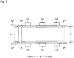
- FIG. 7 is a top view showing at what locations narrowed flange portions SP are provided in the ladder frame 2. More specifically, FIG. 7 is a top view showing the part of the ladder frame 2 surrounding the first battery housing portion 11 of the power supply unit 8.
- narrowed flange portions SP to be provided in the lower flanges 2LF of the left and right side rails 2L, 2R are provided at four locations facing two vehicle front-side corners CP and two vehicle rear-side corners CP of the power supply unit 8.
- the ladder frame 2 has lower flanges 2LF each having a narrowed flange portion SP at a location facing a corner CP of the power supply unit 8 to reduce the possibility of the ladder frame 2 coming into contact with the power supply unit 8 even when the left or the right side rail 2L, 2R is deformed.
- the electric truck 1 according to the first embodiment of the present invention can reduce the risk of the power supply unit 8 receiving intensive impact from the edge of the lower flange 2LF, and thus, ensure the side collision safety of the battery 30 arranged inside the frame.
- the electric truck 1 according to the second embodiment differs from the first embodiment in the configuration of the power supply unit 8 and the locations of the narrowed flange portions SP.
- the difference from the first embodiment will be described below.
- the components common to the first and second embodiments are given the same reference signs; the detailed description thereof will be omitted.
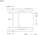
- FIG. 8 is a plan view schematically showing the positional relationship between the lower flanges 2LF of the ladder frame 2 and the power supply unit 8 in the second embodiment of the present invention.
- the PDU 20 is arranged in front of the front surface of the battery housing 10 enclosing the battery 30 (not shown in FIG. 8 ) as viewed in the vehicle longitudinal direction X.
- the PDU 20 is arranged outside the battery housing 10 to be in contact with the front surface of the battery housing 10.
- front corners CP of the power supply unit 8 are front corners of the PDU 20, not corners of the battery housing 10.
- the lower flanges 2LF of the ladder frame 2 have therefore narrowed flange portions SP at the locations facing the front corners of the PDU 20.
- the electric truck 1 according to the third embodiment differs from the second embodiment in the configuration of the power supply unit 8 and the locations of the narrowed flange portions SP.
- the difference from the second embodiment will be described below.
- the components common to the second and third embodiments are given the same reference signs; the detailed description thereof will be omitted.
- FIG. 9 is a plan view schematically showing the positional relationship between the lower flanges 2LF of the ladder frame 2 and the power supply unit 8 in the third embodiment of the present invention.
- the power supply unit 8 has a PDU 20 arranged outside the battery housing 10 to be in contact with the front surface of the battery housing 10, as in the second embodiment.
- the dimension of the PDU 20 measured in the vehicle width direction Y is smaller than that of the battery housing 10.
- the lower flange 2LF of the ladder frame 2 may come into contact with the power supply unit 8 at the corresponding corner CP of the battery housing 10.
- the lower flanges 2LF of the ladder frame 2LF have therefore narrowed flange portions SP at the locations facing corners CP of the battery housing 10.
- the electric truck 1 according to the fourth embodiment differs from the second embodiment in the configuration of the power supply unit 8 and the locations of the narrowed flange portions SP.
- the difference from the second embodiment will be described below.
- the components common to the second and fourth embodiments are given the same reference signs; the detailed description thereof will be omitted.
- FIG. 10 is a plan view schematically showing the positional relationship between the lower flanges 2LF of the ladder frame 2 and the power supply unit 8 in the fourth embodiment of the present invention.
- the power supply unit 8 has a PDU 20 arranged outside the battery housing 10 to be in contact with the front surface of the battery housing 10, as in the second embodiment.
- the dimension of the PDU 20 measured in the vehicle width direction Y is smaller than that of the battery housing 10 but great as compared with the third embodiment.
- the lower flange 2LF of the ladder frame 2 may come into contact with the power supply unit 8 at the corresponding corner CP of the battery housing 10 and at the corresponding corner CP of the PDU 20.
- the lower flanges 2LF of the ladder frame 2LF have therefore narrowed flange potions at the locations facing corners CP of the battery housing 10 and corners CP of the PDU 20.
- the electric truck 1 according to the fifth embodiment differs from the first embodiment in the shape of the battery housing 10 and the support structure for the power supply unit 8. The difference from the first embodiment will be described below.
- the components common to the first and fifth embodiments are given the same reference signs; the detailed description thereof will be omitted.
- FIG. 11 is a cross-sectional view showing the configuration and connecting manner of the elastic support ES for connecting the power supply unit 8 to the ladder frame 2. More specifically, FIG. 11 is a cross-sectional view showing the cross-sections of the power supply unit 8 and the elastic support ES perpendicular to the vehicle longitudinal direction X viewed from the rear of the vehicle.
- the power supply unit 8 has a battery housing 10' in the shape of a rectangular solid, where the whole housing is located on the inner side of the left side rail 2L and on the inner side of the right side rail 2R as viewed in the vehicle width direction Y.
- the elastic support ES has a frame-side bracket ES1 attached to the inner side of the left or right side rail 2L, 2R and a battery-side bracket ES3 attached to the side surface of the power supply unit 8.
- narrowed flange portions SP are provided in the lower flanges 2LF of the ladder frame 2 in the same as in the first embodiment.
Landscapes
- Engineering & Computer Science (AREA)
- Chemical & Material Sciences (AREA)
- Combustion & Propulsion (AREA)
- Transportation (AREA)
- Mechanical Engineering (AREA)
- Arrangement Or Mounting Of Propulsion Units For Vehicles (AREA)
- Body Structure For Vehicles (AREA)
Abstract
Description
- The present invention relates to an electric truck.
- From a viewpoint of reducing environmental burdens, development of electric vehicles, such as full electric cars using a motor as a power source for propulsion in place of an internal combustion engine and hybrid electric cars using both an internal combustion engine and a motor, has been progressing. In such electric vehicles, a battery for propulsion is mounted to drive the motor, and power required to move the vehicle is obtained by supplying electric power from the battery to the motor. In recent years, also in the field of commercial vehicles such as trucks, development of electric vehicles has been being promoted. For example,
Patent Document 1 discloses a holding structure for holding a battery pack for propulsion to a ladder frame of an electric truck. - In order to ensure a sufficient travel range, full electric trucks require mounting of a battery having a large capacity as compared with hybrid electric trucks, etc. In electric trucks, from a viewpoint of ease of securing a space for the battery, it is preferable to arrange the battery between side rails constituting a ladder frame, not on the outer side of either side rail as viewed in the vehicle width direction.
- [Patent Document 1]
Japanese Patent Laid-Open No. 2016-113063 - However, side rails for trucks commonly have a C-shaped cross-section by having flanges provided at each edge of a web to project inward in the vehicle width direction. Thus, when the battery is arranged in the aforementioned manner, if a side rail is deformed in a side collision, the battery does not come into surface contact with the web but receives intensive impact from the edge of a flange which comes into contact with a relatively small contact area. Thus, the electric truck with a battery arranged between the side rails forming a pair has a possibility of the battery becoming greatly damaged in a side collision, and thus, cannot ensure side collision safety.
- The present invention has been made in view of the above problem. An object of the present invention is to provide an electric truck which can ensure side collision safety of a battery arranged inside the frame.
- A first aspect of the present invention is an electric truck traveling by electric power supplied from a battery, comprising a ladder frame including a pair of side rails, the side rails facing each other in vehicle width direction, and a power supply unit including the battery, the power supply unit being arranged between the side rails and connected to the side rails, wherein the side rails each have flanges having a predetermined width provided at each edge of a web, wherein the flange facing at least one of corners of the power supply device has at least one narrowed flange portion having a width smaller than the predetermined width at a location facing one of the corners of the power supply unit as viewed in the vehicle width direction.
- In the electric truck in which the power supply unit including the battery is connected to the side rails forming a pair, the ladder frame has increased rigidity against side impact in the region corresponding to the power supply unit. Meanwhile, the ladder frame has relatively low rigidity at the locations facing corners of the power supply unit as viewed in the vehicle width direction, and thus, when receiving impact exceeding the rigidity in a side collision, the ladder frame may be deformed in a region near a corner of the power supply unit. The side rail thus deformed may give intensive impact to the power supply unit with the edge of a flange which comes into contact with a relatively small contact area, thereby damaging the battery included in the power supply unit.
- Thus, in the electric truck according to the first embodiment of the present invention, a narrowed flange portion is provided in the flange of the ladder frame which faces a corner of the power supply unit to reduce the possibility of the side rail coming into contact with the power supply unit even when the side rail is deformed. The electric truck according to the first aspect of the present invention can thus ensure the side collision safety of the battery arranged inside the frame.
- A second aspect of the present invention is an electric truck according to the first aspect in which the narrowed flange portions are provided to face two vehicle front-side corners of the power supply unit, respectively.
- In the electric truck according to the second aspect of the present invention, the narrowed flange portions are provided at the locations facing the vehicle front-side corners of the power supply unit at which the side rail is most likely to come into contact with the power supply unit when the ladder frame is deformed. The risk of the battery becoming damaged by contact between the side rail and the power supply unit is therefore reduced effectively.
- A third aspect of the present invention is an electric truck according to the first or second aspect in which the narrowed flange portions are provided to face two vehicle rear-side corners of the power supply unit, respectively.
- In the electric truck according to the third aspect of the present invention, the narrowed flange portions are provided at the locations facing the vehicle rear-side corners of the power supply unit at which the side rail is relatively highly likely to come into contact with the power supply unit when the ladder frame is deformed. The risk of the battery becoming damaged by contact between the side rail and the power supply unit is therefore reduced effectively.
- A fourth aspect of the present invention is an electric truck according to any of the first to third aspects in which the narrowed flange portion has an arc-shaped outline.
- In the electric truck according to the fourth aspect of the present invention in which the narrowed flange portion provided in the flange of the side rail has an arc-shaped outline, stress concentration in the narrowed flange portion is prevented when force is applied to the frame during traveling of the vehicle.
- A fifth aspect of the present invention is an electric truck according to any of the first to fourth aspects in which the narrowed flange portion is provided such that the most narrowed point at which the narrowed flange portion has the smallest width is in alignment with the corresponding corner of the power supply unit as viewed in the vehicle width direction.
- In the electric truck according to the fifth aspect of the present invention in which the power supply unit is arranged with a corner facing the most narrowed point at which the narrowed flange portion has the smallest width, the risk of the power supply unit becoming damaged by contact with the ladder frame is reduced effectively.
-
- [
FIG. 1] FIG. 1 is a top view schematically showing the total structure of an electric truck according to a first embodiment of the present invention. - [
FIG. 2] FIG. 2 is a perspective view showing the general shape of a power supply unit mounted on the electric truck. - [
FIG. 3] FIG. 3 is a cross-sectional view showing the configuration and connecting manner of an elastic support for connecting the power supply unit to a ladder frame. - [
FIG. 4] FIG. 4 is a top view showing the electric truck with the ladder frame deformed in a side collision. - [
FIG. 5] FIG. 5 is a fragmentary enlarged view showing a part of the ladder frame near a corner of the power supply unit. - [
FIG. 6] FIG. 6 is a plan view schematically showing the positional relationship between narrowed flange portions of lower flanges and a first battery housing portion of a battery housing. - [
FIG. 7] FIG. 7 is a top view showing at what locations narrowed flange portions are provided in the ladder frame. - [
FIG. 8] FIG. 8 is a plan view schematically showing the positional relationship between lower flanges of a ladder frame and a power supply unit in a second embodiment of the present invention. - [
FIG. 9] FIG. 9 is a plan view schematically showing the positional relationship between lower flanges of a ladder frame and a power supply unit in a third embodiment of the present invention. - [
FIG. 10] FIG. 10 is a plan view schematically showing the positional relationship between lower flanges of a ladder frame and a power supply unit in a fourth embodiment of the present invention. - [
FIG. 11] FIG. 11 is a cross-sectional view showing the configuration and connecting manner of an elastic support for connecting a power supply unit to a ladder frame. - With reference to the accompanying drawings, embodiments of the present invention will be described in detail. The present invention is not limited to the description given below; it can be carried out with any desired alteration that does not change the essentials thereof. The drawings used in explanation of the embodiments show components, schematically; in order to help understanding, the drawings may contain partial emphasis, enlargement, contraction, omission or the like, and thus, may not necessarily show the components at an accurate scale and in an accurate shape.
-
FIG. 1 is a top view schematically showing the total structure of anelectric truck 1 according to a first embodiment of the present invention. As shown inFIG. 1 , theelectric truck 1 according to the present embodiment comprises aladder frame 2, acab 3, acargo box 4,wheel mechanisms 5, adrive unit 6, a drivepower supply device 7 and apower supply unit 8.FIG. 1 is a top view of theelectric truck 1 viewed from the top of theelectric truck 1 through thecab 3 and thecargo box 4. - The
ladder frame 2 comprises a left and aright side rails right side rails electric truck 1. They are arranged parallel to each other to face each other in the vehicle width direction Y. The cross-members CM1 to CM8 connect theleft side rail 2L to theright side rail 2R at their respective positions to form a ladder-shaped frame referred to as a "ladder frame 2". Theladder frame 2 supports thecab 3, thecargo box 4, thedrive unit 6, the drivepower supply device 7, thepower supply unit 8 and other heavy objects mounted on theelectric truck 1. - The
cab 3 is a structure with a driver's seat, not shown, and arranged over the front of theladder frame 2. Thecargo box 4 is a structure into which cargos to be transported by theelectric truck 1 are loaded, and arranged over the rear of theladder frame 2. - In the present embodiment, the
wheel mechanism 5 arranged in the front of the vehicle comprises a left and a rightfront wheels 5a and afront axle 5b, or shaft for thefront wheels 5a, while thewheel mechanism 5 arranged in the rear of the vehicle comprises two left and two rightrear wheels 5c and arear axle 5d, or shaft for therear wheels 5c. In theelectric truck 1 according to the present embodiment, therear wheels 5c are drive wheels to which drive power is transmitted to move theelectric truck 1. Thewheel mechanisms 5 are attached to theladder frame 2 by means of a suspension mechanism, not shown, and support the weight of theelectric truck 1. - The
drive unit 6 comprises amotor 6a, aspeed reducing mechanism 6b and adifferential mechanism 6c. By being supplied with AC power from the drivepower supply device 7 described later, themotor 6a produces drive power required to move theelectric truck 1. Thespeed reducing mechanism 6b comprises a plurality of gears, not shown, to convert rotational power produced by themotor 6a into a reduced speed and transmit it to thedifferential mechanism 6c. Thedifferential mechanism 6c distributes the power transmitted from thespeed reducing mechanism 6b to the left and rightrear wheels 5c. In other words, thedrive unit 6 is configured such that drive power produced by themotor 6a is converted into a reduced rotational speed suited for moving the vehicle and transmitted to therear axle 5d by means of thespeed reducing mechanism 6b and thedifferential mechanism 6c. Thedrive unit 6 can thus rotate therear wheels 5c via therear axle 5d, thereby moving theelectric truck 1. In thedrive unit 6, a front portion as viewed in the vehicle longitudinal direction X is suspended by the cross-member CM5 attached to theladder frame 2. - The drive
power supply device 7 is an inverter. It converts DC power supplied from thepower supply unit 8 into AC power and supplies it to themotor 6a, and controls the rotational speed of themotor 6a according to an accelerator operation performed in theelectric truck 1. - The
power supply unit 8 comprises a battery 30 (seeFIG. 3 ) which supplies electric power to themotor 6a and thus functions primarily as an energy source for moving theelectric truck 1. Thepower supply unit 8 includes a plurality of battery modules BM of relatively large size and capacity (seeFIG. 3 ) to store electric power required for theelectric truck 1. Thepower supply unit 8 can supply electric power also to auxiliary electric devices, not shown, mounted on theelectric truck 1 via aPDU 20, described later. The configuration of thepower supply unit 8 will be described later in detail. - In the present embodiment, the
ladder frame 2 has a plurality of elastic supports ES to elastically support thepower supply unit 8 in the vehicle width direction Y at the opposite sides. Specifically, three elastic supports ES are provided on the outer side of theleft side rail 2L and on the outer side of theright side rail 2R, each (six in total), as viewed in the vehicle width direction Y. The number of the elastic supports ES may however be appropriately changed depending on the weight and size of thepower supply unit 8. The configuration of the elastic support ES will be described later in detail. -
FIG. 2 is a perspective view showing the general shape of thepower supply unit 8 mounted on theelectric truck 1. In the present embodiment, thepower supply unit 8 comprises abattery housing 10, aPDU 20 and abattery 30 comprising a plurality of battery modules BM (omitted inFIG. 2 ; seeFIG. 3 ). - The
battery housing 10 comprises a firstbattery housing portion 11 and a secondbattery housing portion 12 combined together, where the first and second battery housing portions are in the shape of a roughly rectangular solid and have the same length, or dimension measured in the vehicle longitudinal direction X. As viewed in the vehicle longitudinal direction X, the firstbattery housing portion 11 has a low-height portion in the front, in which thePDU 20 is enclosed. Thebattery housing 10 is thus shaped not to interfere with the cross-member CM4. Arranging the firstbattery housing portion 11 such that thePDU 20 enclosing portion is, between the side rails, in alignment with the cross member CM4 as viewed in the vehicle height direction Z enables effective use of space, and thus, contributes to maximizing the space to be occupied by thebattery 30. - The first
battery housing portion 11 has a width, or dimension measured in the vehicle width direction Y allowing it to be located between the left and right side rails 2L, 2R. Meanwhile, the secondbattery housing portion 12 has a width, or dimension measured in the vehicle width direction Y equal to or greater than the width of theladder frame 2. The secondbattery housing portion 12 is joined to the firstbattery housing portion 11 from below, as viewed in the vehicle height direction Z. - The
battery housing 10 has thus an inverted T-shaped cross-section perpendicular to the vehicle longitudinal direction X. Thebattery housing 10 is arranged such that the left and right side rails 2L, 2R extend over the steps formed due to the difference in width between the first and the secondbattery housing portions - For connecting the elastic supports ES, the
battery housing 10 has a plurality of fixingregions 13 on thehousing sides 12S, or outer side surfaces of the secondbattery housing portion 12 as viewed in the vehicle width direction Y. - The
PDU 20 is a power distribution unit which collects electric power from the battery modules BM and distributes part of the collected electric power to the auxiliary electric devices via a harness (not shown). Although in the present embodiment thePDU 20 is enclosed in thebattery housing 10 with thebattery 30, in some layout of components between the side rails it may be arranged outside thebattery housing 10. -
FIG. 3 is a cross-sectional view showing the configuration and connecting manner of the elastic support ES for connecting thepower supply unit 8 to theladder frame 2. More specifically,FIG. 3 is a cross-sectional view showing the cross-sections of thepower supply unit 8 and the elastic support ES perpendicular to the vehicle longitudinal direction X viewed from the rear of the vehicle. - The
power supply unit 8 includes a plurality of battery modules BM, where the number of the battery modules BM depends on the size of thebattery housing 10. The shape and arrangement of the battery modules BM may be changed in various ways. - The elastic support ES comprises a frame-side bracket ES1, an elastic connector ES2 and a battery-side bracket ES3. The frame-side bracket ES1 is a fixing member of metal. It is bolted to the outer side of the left or
right side rail battery housing 10 in the above-mentionedfixing region 13. - The elastic supports ES thus elastically attach the
power supply unit 8 to theladder frame 2, and even when stress is produced by twist or lateral bend of the frame during traveling of theelectric truck 1, reduce the stress transmitted to thepower supply unit 8 by their damping effect. The risk that that thebattery 30 included in thepower supply unit 8 will be damaged by the stress is therefore reduced. - Meanwhile, for the left and right side rails 2L, 2R, this means that they are elastically connected to each other by means of the elastic supports ES connected to each rail and the
battery housing 10 constituting thepower supply unit 8. The plurality of elastic supports ES thus increases the rigidity of theladder frame 2 by connecting the side rails to each other in cooperation with thepower supply unit 8, while reducing the stress applied due to twist or lateral bend of the frame. The plurality of elastic supports thus fulfills the same function as the cross-member. - Here, how the
power supply unit 8 is influenced when theelectric truck 1 is struck in a side by another vehicle or the like will be explained.FIG. 4 is a top view showing theelectric truck 1 with theladder frame 2 deformed in a side collision. Thecargo box 4 is omitted in the Figure. More specifically,FIG. 4 schematically shows theelectric vehicle 1 assuming that another vehicle BC has struck the left side of theelectric truck 1 in the vehicle width direction Y in the region of thepower supply unit 8, so that theladder fame 2 has been deformed. - Since the
electric truck 1 has relatively high rigidity in the region including thecab 3 and thewheel mechanism 5 including thefront axle 5b and the region including thewheel mechanism 5 including therear axle 5c, indicated as regions R1 and R5 inFIG. 4 , theelectric truck 1 is not significantly deformed in these regions in a side collision. More specifically, in region R1, displacement of theladder frame 2 is limited by frictional force produced between the left and rightfront wheels 5a and the road surface, and thefront axle 5b and the cross-members CM1 to CM3 arranged close to each other reinforce theladder frame 2. Thus, in region R1, deformation of the ladder frame by side impact is restricted. Likewise, in region R5, displacement of theladder frame 2 is limited by frictional force produced between the left and rightrear wheels 5c and the road surface, and therear axle 5d and the cross-members CM5 to CM8 arranged close to each other reinforce theladder frame 2. Thus, in region R5, deformation of theladder frame 2 by side impact is restricted. - Here, the
power supply unit 8, which is connected to the left and right side rails 2L, 2R using the elastic connectors ES2, can fulfill the function of reinforcing the ladder frame like the cross-member. Thus, even when theladder frame 2 receives side impact in the region corresponding to thepower supply unit 8 indicated as region R3, deformation of the side rail in the region receiving impact is restricted. - However, the
ladder frame 2 has low rigidity in region R2 between thecab 3 and the elastic connectors ES2 in the front row and region R4 between the elastic connectors ES2 in the rear row and the cross-member CM5, as compared with regions R1, R3 and R5. Thus, if theladder frame 2 receives impact exceeding its rigidity in a side collision in which theelectric truck 1 is struck in the region corresponding to thepower supply unit 8, theladder frame 2 may not be able to withstand the impact and be deformed in regions R2 and R4. - In such case, the
power supply unit 8 receives intensive impact from the edge of a flange of the left orright side rail deformed ladder frame 2 as viewed in the vehicle width direction Y, which may cause great damage to theenclosed battery 30. Side collision safety may therefore not be able to be ensured. - In this view, in the
electric truck 1 according to the present invention, a cutout is provided in the left and right side rails 2L, 2R, as described below, to reduce the possibility of thepower supply unit 8 becoming damaged by intensive impact from the side rail in a side collision. -
FIG. 5 is a fragmentary enlarged view showing a part of theladder frame 2 near a corner of thepower supply unit 8. Specifically,FIG. 5 is an enlarged perspective view of the part enclosed by a dashed line inFIG. 4 , more specifically a perspective view showing a right front corner CP of the firstbattery housing portion 11 of thebattery housing 10 constituting thepower supply unit 8 and the part of theright side rail 2R facing the corner CP, viewed in the vehicle width direction Y from the inside. - Like a side rail in conventional common trucks, the
right side rail 2R comprises aweb 2W providing a surface perpendicular to the vehicle width direction Y and upper and lower flanges 2UF, 2LF having a predetermined width, provided at the top and bottom edges of theweb 2W as viewed in the vehicle height direction Z to project inward in the vehicle width direction Y. Theright side rail 2R has thus a C-shaped cross-section. Like theright side rail 2R, theleft side rail 2L comprises aweb 2W and an upper and a lower flanges 2UF, 2LF. - As shown in
FIG. 5 , theright side rail 2R has a narrowed flange portion SP having a width smaller than the predetermined width at a location facing the corner CP of the battery housing as viewed in the vehicle width direction Y. The narrowed flange portion SP provides an increased distance between the lower flange 2LF and the corner CP of thebattery housing 10. Thus, when theelectric truck 1 receives side impact so that theladder frame 2 is deformed, the possibility of the edge of the lower flange 2LF coming into contact with the corner CP of thebattery housing 10 is reduced, so that the risk of thepower supply unit 8 becoming damaged is reduced. -
FIG. 6 is a plan view schematically showing the positional relationship between the narrowed flange portions SP of the lower flanges 2LF and the firstbattery housing portion 11 of thebattery housing 1. InFIG. 6 , the boundary between the regions of the firstbattery housing portion 11 in which thePDU 20 and thebattery 30 are arranged respectively is indicated by a dashed line. - As seen in
FIG. 6 , the left and right side rails 2L, 2R each have a narrowed flange portion SP in the lower flange 2LF, which is provided by a cutout having an arc-shaped outline. This prevents a stress concentration in the narrowed flange portion SP even when force is applied to the frame during traveling of the vehicle by, for example twist or lateral bend of theladder frame 2 during traveling of theelectric truck 2. - Further, the narrowed flange portion SP has the most narrowed point at which the narrowed flange portion has the smallest width, at a location indicated by a dashed-line arrow, and the narrowed flange portion SP is arranged such that the most narrowed point is in alignment with the corresponding corner CP of the
battery housing 10 as viewed in the vehicle width direction Y. By this, the risk of thepower supply unit 8 becoming damaged by theladder frame 2 coming into contact with the corner CP of thebattery housing 10 is reduced effectively. -
FIG. 7 is a top view showing at what locations narrowed flange portions SP are provided in theladder frame 2. More specifically,FIG. 7 is a top view showing the part of theladder frame 2 surrounding the firstbattery housing portion 11 of thepower supply unit 8. - As shown in
FIG. 7 , in the present embodiment, narrowed flange portions SP to be provided in the lower flanges 2LF of the left and right side rails 2L, 2R are provided at four locations facing two vehicle front-side corners CP and two vehicle rear-side corners CP of thepower supply unit 8. By this, the possibility of thepower supply unit 8 becoming damaged by impact from theladder frame 2 is reduced in regions in which theladder fame 2 is relatively low in rigidity and easily deformed, such as regions R2, R4 shown inFIG. 4 . - As described above, in the
electric truck 1 according to the present invention, theladder frame 2 has lower flanges 2LF each having a narrowed flange portion SP at a location facing a corner CP of thepower supply unit 8 to reduce the possibility of theladder frame 2 coming into contact with thepower supply unit 8 even when the left or theright side rail electric truck 1 according to the first embodiment of the present invention can reduce the risk of thepower supply unit 8 receiving intensive impact from the edge of the lower flange 2LF, and thus, ensure the side collision safety of thebattery 30 arranged inside the frame. - Next, a second embodiment of the present invention will be described. The
electric truck 1 according to the second embodiment differs from the first embodiment in the configuration of thepower supply unit 8 and the locations of the narrowed flange portions SP. The difference from the first embodiment will be described below. The components common to the first and second embodiments are given the same reference signs; the detailed description thereof will be omitted. -
FIG. 8 is a plan view schematically showing the positional relationship between the lower flanges 2LF of theladder frame 2 and thepower supply unit 8 in the second embodiment of the present invention. In the second embodiment, thePDU 20 is arranged in front of the front surface of thebattery housing 10 enclosing the battery 30 (not shown inFIG. 8 ) as viewed in the vehicle longitudinal direction X. Specifically, in the second embodiment, thePDU 20 is arranged outside thebattery housing 10 to be in contact with the front surface of thebattery housing 10. - In this configuration, front corners CP of the
power supply unit 8 are front corners of thePDU 20, not corners of thebattery housing 10. The lower flanges 2LF of theladder frame 2 have therefore narrowed flange portions SP at the locations facing the front corners of thePDU 20. Thus, also the second embodiment of the present invention in which thepower supply unit 8 is configured to have thePDU 20 arranged outside thebattery housing 10 can reduce the risk of thepower supply unit 8 becoming damaged by impact from theladder frame 2. - Next, a third embodiment of the present invention will be described. The
electric truck 1 according to the third embodiment differs from the second embodiment in the configuration of thepower supply unit 8 and the locations of the narrowed flange portions SP. The difference from the second embodiment will be described below. The components common to the second and third embodiments are given the same reference signs; the detailed description thereof will be omitted. -
FIG. 9 is a plan view schematically showing the positional relationship between the lower flanges 2LF of theladder frame 2 and thepower supply unit 8 in the third embodiment of the present invention. In the third embodiment, thepower supply unit 8 has aPDU 20 arranged outside thebattery housing 10 to be in contact with the front surface of thebattery housing 10, as in the second embodiment. However, in the third embodiment, the dimension of thePDU 20 measured in the vehicle width direction Y is smaller than that of thebattery housing 10. - In this configuration, if the
ladder frame 2 is deformed in region R2 when theelectric truck 1 receives side impact, the lower flange 2LF of theladder frame 2 may come into contact with thepower supply unit 8 at the corresponding corner CP of thebattery housing 10. In the third embodiment, the lower flanges 2LF of the ladder frame 2LF have therefore narrowed flange portions SP at the locations facing corners CP of thebattery housing 10. - Next, a fourth embodiment of the present invention will be described. The
electric truck 1 according to the fourth embodiment differs from the second embodiment in the configuration of thepower supply unit 8 and the locations of the narrowed flange portions SP. The difference from the second embodiment will be described below. The components common to the second and fourth embodiments are given the same reference signs; the detailed description thereof will be omitted. -
FIG. 10 is a plan view schematically showing the positional relationship between the lower flanges 2LF of theladder frame 2 and thepower supply unit 8 in the fourth embodiment of the present invention. In the fourth embodiment, thepower supply unit 8 has aPDU 20 arranged outside thebattery housing 10 to be in contact with the front surface of thebattery housing 10, as in the second embodiment. However, in the fourth embodiment, the dimension of thePDU 20 measured in the vehicle width direction Y is smaller than that of thebattery housing 10 but great as compared with the third embodiment. - In this configuration, if the
ladder frame 2 is deformed in region R2 when theelectric truck 1 receives side impact, the lower flange 2LF of theladder frame 2 may come into contact with thepower supply unit 8 at the corresponding corner CP of thebattery housing 10 and at the corresponding corner CP of thePDU 20. In the fourth embodiment, the lower flanges 2LF of the ladder frame 2LF have therefore narrowed flange potions at the locations facing corners CP of thebattery housing 10 and corners CP of thePDU 20. - Next, a fifth embodiment of the present invention will be described. The
electric truck 1 according to the fifth embodiment differs from the first embodiment in the shape of thebattery housing 10 and the support structure for thepower supply unit 8. The difference from the first embodiment will be described below. The components common to the first and fifth embodiments are given the same reference signs; the detailed description thereof will be omitted. -
FIG. 11 is a cross-sectional view showing the configuration and connecting manner of the elastic support ES for connecting thepower supply unit 8 to theladder frame 2. More specifically,FIG. 11 is a cross-sectional view showing the cross-sections of thepower supply unit 8 and the elastic support ES perpendicular to the vehicle longitudinal direction X viewed from the rear of the vehicle. - In the fifth embodiment, the
power supply unit 8 has a battery housing 10' in the shape of a rectangular solid, where the whole housing is located on the inner side of theleft side rail 2L and on the inner side of theright side rail 2R as viewed in the vehicle width direction Y. - In the fifth embodiment, the elastic support ES has a frame-side bracket ES1 attached to the inner side of the left or
right side rail power supply unit 8. - In the fifth embodiment in which the
power supply unit 8 is in the shape of a rectangular solid, narrowed flange portions SP are provided in the lower flanges 2LF of theladder frame 2 in the same as in the first embodiment. By this, the possibility of thepower supply unit 8 becoming damaged by contact between theladder frame 2 and the battery housing 10' is reduced. -
- 1
- Electric truck
- 2
- Ladder frame
- 2L
- Left side rail
- 2R
- Right side rail
- 2W
- Web
- 2UF
- Upper flange
- 2LF
- Lower flange
- 8
- Power supply unit
- 10
- Battery housing
- 20
- PDU
- 30
- Battery
- CP
- Corner
- SP
- Narrowed flange portion
Claims (5)
- An electric truck traveling by electric power supplied from a battery, comprising:a ladder frame including a pair of side rails, the side rails facing each other in vehicle width direction, anda power supply unit including the battery, the power supply unit being arranged between the side rails and connected to the side rails, whereinthe side rails each have flanges having a predetermined width provided at each edge of a web, whereinthe flange facing at least one of corners of the power supply device has at least one narrowed flange portion having a width smaller than the predetermined width at a location facing one of the corners of the power supply unit as viewed in the vehicle width direction.
- The electric truck according to claim 1, wherein the narrowed flange portions are provided to face two vehicle front-side corners of the power supply unit, respectively.
- The electric truck according to claim 1 or 2, wherein the narrowed flange portions are provided to face two vehicle rear-side corners of the power supply unit, respectively.
- The electric truck according to any of claims 1 to 3, wherein the narrowed flange portion has an arc-shaped outline.
- The electric truck according to any of claims 1 to 4, wherein the narrowed flange portion is provided such that the most narrowed point at which the narrowed flange portion has the smallest width is in alignment with the corresponding corner of the power supply unit as viewed in the vehicle width direction.
Applications Claiming Priority (2)
| Application Number | Priority Date | Filing Date | Title |
|---|---|---|---|
| JP2019130450A JP7360834B2 (en) | 2019-07-12 | 2019-07-12 | electric truck |
| PCT/JP2020/023704 WO2021010080A1 (en) | 2019-07-12 | 2020-06-17 | Electric truck |
Publications (3)
| Publication Number | Publication Date |
|---|---|
| EP3984864A1 true EP3984864A1 (en) | 2022-04-20 |
| EP3984864A4 EP3984864A4 (en) | 2023-07-19 |
| EP3984864B1 EP3984864B1 (en) | 2025-12-10 |
Family
ID=74209773
Family Applications (1)
| Application Number | Title | Priority Date | Filing Date |
|---|---|---|---|
| EP20841642.0A Active EP3984864B1 (en) | 2019-07-12 | 2020-06-17 | Electric truck |
Country Status (5)
| Country | Link |
|---|---|
| US (1) | US11975600B2 (en) |
| EP (1) | EP3984864B1 (en) |
| JP (1) | JP7360834B2 (en) |
| CN (1) | CN114096429B (en) |
| WO (1) | WO2021010080A1 (en) |
Cited By (1)
| Publication number | Priority date | Publication date | Assignee | Title |
|---|---|---|---|---|
| WO2025031919A1 (en) * | 2023-08-04 | 2025-02-13 | Designwerk Technologies Ag | Battery pack |
Families Citing this family (7)
| Publication number | Priority date | Publication date | Assignee | Title |
|---|---|---|---|---|
| JP7272867B2 (en) * | 2019-05-31 | 2023-05-12 | メルセデス・ベンツ グループ アクチェンゲゼルシャフト | frame for electric truck |
| JP7360834B2 (en) * | 2019-07-12 | 2023-10-13 | メルセデス・ベンツ グループ アクチェンゲゼルシャフト | electric truck |
| JP7422518B2 (en) * | 2019-11-06 | 2024-01-26 | ダイムラー トラック エージー | Support device for vehicle battery pack and electric vehicle |
| US10919575B1 (en) * | 2020-07-30 | 2021-02-16 | Ree Automotive Ltd | Vehicle chassis platform |
| US11260909B2 (en) | 2020-06-03 | 2022-03-01 | Ree Automotive Ltd | Vehicle chassis platform |
| GB2613027A (en) | 2021-11-23 | 2023-05-24 | Daimler Truck AG | Side impact protection longitudinal member for a commercial vehicle as well as arrangement |
| US20240072351A1 (en) * | 2022-08-30 | 2024-02-29 | Bollinger Motors Inc. | Semi-isolated ev battery mount for torsionally flexible chasis |
Family Cites Families (24)
| Publication number | Priority date | Publication date | Assignee | Title |
|---|---|---|---|---|
| JPH08324453A (en) * | 1995-05-31 | 1996-12-10 | Isuzu Motors Ltd | Vehicle heavy loading structure |
| JP2007038961A (en) | 2005-08-05 | 2007-02-15 | Mazda Motor Corp | Auto body front structure |
| JP5966824B2 (en) * | 2012-09-28 | 2016-08-10 | 三菱自動車工業株式会社 | Track-type electric vehicle frame structure |
| JP5742967B2 (en) * | 2013-02-20 | 2015-07-01 | トヨタ自動車株式会社 | Electric car |
| JP2016113063A (en) | 2014-12-16 | 2016-06-23 | ダイムラー・アクチェンゲゼルシャフトDaimler AG | Battery box-holding structure |
| JP6344270B2 (en) | 2015-03-06 | 2018-06-20 | トヨタ自動車株式会社 | Battery unit mounting structure |
| KR20170079052A (en) * | 2015-12-30 | 2017-07-10 | 에이치엘그린파워 주식회사 | Battery fixing frame assembly and Vehicle having the same |
| JP6677188B2 (en) * | 2017-02-06 | 2020-04-08 | トヨタ自動車株式会社 | Power unit mounting structure |
| JP2018187976A (en) | 2017-04-28 | 2018-11-29 | ダイムラー・アクチェンゲゼルシャフトDaimler AG | Electric vehicle |
| JP6929151B2 (en) * | 2017-07-06 | 2021-09-01 | ダイムラー・アクチェンゲゼルシャフトDaimler AG | Vehicle side rails |
| JP6794949B2 (en) * | 2017-07-13 | 2020-12-02 | トヨタ自動車株式会社 | Vehicle front structure |
| GB2578323A (en) * | 2018-10-23 | 2020-05-06 | Ford Global Tech Llc | Powertrain mount assemblies |
| US12420869B2 (en) * | 2019-07-02 | 2025-09-23 | Canoo Technologies Inc. | Method to reduced lateral deflection of longitudinal members in side impact |
| JP7360834B2 (en) * | 2019-07-12 | 2023-10-13 | メルセデス・ベンツ グループ アクチェンゲゼルシャフト | electric truck |
| JP7283006B2 (en) * | 2019-08-27 | 2023-05-30 | メルセデス・ベンツ グループ アクチェンゲゼルシャフト | electric truck |
| JP7422518B2 (en) * | 2019-11-06 | 2024-01-26 | ダイムラー トラック エージー | Support device for vehicle battery pack and electric vehicle |
| JP2021075111A (en) * | 2019-11-06 | 2021-05-20 | ダイムラー・アクチェンゲゼルシャフトDaimler AG | Support device of battery pack for vehicle |
| JP2021115964A (en) * | 2020-01-27 | 2021-08-10 | ダイムラー・アクチェンゲゼルシャフトDaimler AG | Vehicle frame and vehicle |
| JP7381355B2 (en) * | 2020-01-31 | 2023-11-15 | ダイムラー トラック エージー | Side rails and electric vehicles |
| KR102792069B1 (en) * | 2020-09-01 | 2025-04-08 | 현대모비스 주식회사 | Chassis platform module for electric vehicle |
| US12269538B2 (en) * | 2020-12-18 | 2025-04-08 | Optimal Electric Vehicles Corporation | Low floor electric vehicle |
| EP4351908A4 (en) * | 2021-05-26 | 2025-04-23 | Magna International Inc. | Skateboard chassis assembly for an electric vehicle |
| US11603137B2 (en) * | 2021-06-24 | 2023-03-14 | Volvo Car Corporation | Subframe assembly for a vehicle utilizing straight extruded longitudinal siderail members |
| DE102021121526A1 (en) * | 2021-08-19 | 2023-02-23 | Bayerische Motoren Werke Aktiengesellschaft | pressure vessel assembly and motor vehicle |
-
2019
- 2019-07-12 JP JP2019130450A patent/JP7360834B2/en active Active
-
2020
- 2020-06-17 US US17/626,388 patent/US11975600B2/en active Active
- 2020-06-17 CN CN202080050989.0A patent/CN114096429B/en active Active
- 2020-06-17 WO PCT/JP2020/023704 patent/WO2021010080A1/en not_active Ceased
- 2020-06-17 EP EP20841642.0A patent/EP3984864B1/en active Active
Cited By (1)
| Publication number | Priority date | Publication date | Assignee | Title |
|---|---|---|---|---|
| WO2025031919A1 (en) * | 2023-08-04 | 2025-02-13 | Designwerk Technologies Ag | Battery pack |
Also Published As
| Publication number | Publication date |
|---|---|
| JP2021014208A (en) | 2021-02-12 |
| JP7360834B2 (en) | 2023-10-13 |
| WO2021010080A1 (en) | 2021-01-21 |
| US11975600B2 (en) | 2024-05-07 |
| US20220250458A1 (en) | 2022-08-11 |
| CN114096429A (en) | 2022-02-25 |
| CN114096429B (en) | 2024-04-19 |
| EP3984864A4 (en) | 2023-07-19 |
| EP3984864B1 (en) | 2025-12-10 |
Similar Documents
| Publication | Publication Date | Title |
|---|---|---|
| EP3984864B1 (en) | Electric truck | |
| EP3840972B1 (en) | Battery system for heavy duty vehicles | |
| US11465482B2 (en) | Vehicle battery pack support device | |
| CN112292278B (en) | Vehicle battery pack support device | |
| US11894533B2 (en) | Electric vehicle | |
| US12220979B2 (en) | Support device for vehicle battery pack and electric vehicle | |
| US8978617B2 (en) | Mounting structure for battery and fuel tank of gasoline-electric hybrid vehicle | |
| US11541738B2 (en) | Vehicle battery housing, vehicle battery pack and electric vehicle | |
| US12049131B2 (en) | Electric truck frame | |
| CN114987615B (en) | Frame structure for vehicle | |
| WO2019244858A1 (en) | Vehicular battery pack support device | |
| WO2021153065A1 (en) | Side rail and electric vehicle | |
| JP2019217908A (en) | Vehicle battery pack support device | |
| JP2020083267A (en) | Vehicle battery pack support device and manufacturing method of the same |
Legal Events
| Date | Code | Title | Description |
|---|---|---|---|
| STAA | Information on the status of an ep patent application or granted ep patent |
Free format text: STATUS: THE INTERNATIONAL PUBLICATION HAS BEEN MADE |
|
| PUAI | Public reference made under article 153(3) epc to a published international application that has entered the european phase |
Free format text: ORIGINAL CODE: 0009012 |
|
| STAA | Information on the status of an ep patent application or granted ep patent |
Free format text: STATUS: REQUEST FOR EXAMINATION WAS MADE |
|
| 17P | Request for examination filed |
Effective date: 20220111 |
|
| AK | Designated contracting states |
Kind code of ref document: A1 Designated state(s): AL AT BE BG CH CY CZ DE DK EE ES FI FR GB GR HR HU IE IS IT LI LT LU LV MC MK MT NL NO PL PT RO RS SE SI SK SM TR |
|
| RAP1 | Party data changed (applicant data changed or rights of an application transferred) |
Owner name: DAIMLER TRUCK AG |
|
| DAV | Request for validation of the european patent (deleted) | ||
| DAX | Request for extension of the european patent (deleted) | ||
| A4 | Supplementary search report drawn up and despatched |
Effective date: 20230616 |
|
| RIC1 | Information provided on ipc code assigned before grant |
Ipc: B60K 1/04 20190101ALI20230612BHEP Ipc: B62D 21/02 20060101AFI20230612BHEP |
|
| STAA | Information on the status of an ep patent application or granted ep patent |
Free format text: STATUS: EXAMINATION IS IN PROGRESS |
|
| 17Q | First examination report despatched |
Effective date: 20240418 |
|
| GRAP | Despatch of communication of intention to grant a patent |
Free format text: ORIGINAL CODE: EPIDOSNIGR1 |
|
| STAA | Information on the status of an ep patent application or granted ep patent |
Free format text: STATUS: GRANT OF PATENT IS INTENDED |
|
| INTG | Intention to grant announced |
Effective date: 20250708 |
|
| P01 | Opt-out of the competence of the unified patent court (upc) registered |
Free format text: CASE NUMBER: UPC_APP_7003_3984864/2025 Effective date: 20250912 |
|
| GRAS | Grant fee paid |
Free format text: ORIGINAL CODE: EPIDOSNIGR3 |
|
| GRAA | (expected) grant |
Free format text: ORIGINAL CODE: 0009210 |
|
| STAA | Information on the status of an ep patent application or granted ep patent |
Free format text: STATUS: THE PATENT HAS BEEN GRANTED |
|
| AK | Designated contracting states |
Kind code of ref document: B1 Designated state(s): AL AT BE BG CH CY CZ DE DK EE ES FI FR GB GR HR HU IE IS IT LI LT LU LV MC MK MT NL NO PL PT RO RS SE SI SK SM TR |
|
| REG | Reference to a national code |
Ref country code: CH Ref legal event code: F10 Free format text: ST27 STATUS EVENT CODE: U-0-0-F10-F00 (AS PROVIDED BY THE NATIONAL OFFICE) Effective date: 20251210 Ref country code: GB Ref legal event code: FG4D |
|
| REG | Reference to a national code |
Ref country code: IE Ref legal event code: FG4D |
|
| REG | Reference to a national code |
Ref country code: DE Ref legal event code: R096 Ref document number: 602020063783 Country of ref document: DE |
|
| PG25 | Lapsed in a contracting state [announced via postgrant information from national office to epo] |
Ref country code: ES Free format text: LAPSE BECAUSE OF FAILURE TO SUBMIT A TRANSLATION OF THE DESCRIPTION OR TO PAY THE FEE WITHIN THE PRESCRIBED TIME-LIMIT Effective date: 20251210 |
|
| REG | Reference to a national code |
Ref country code: LT Ref legal event code: MG9D |
|
| PG25 | Lapsed in a contracting state [announced via postgrant information from national office to epo] |
Ref country code: NO Free format text: LAPSE BECAUSE OF FAILURE TO SUBMIT A TRANSLATION OF THE DESCRIPTION OR TO PAY THE FEE WITHIN THE PRESCRIBED TIME-LIMIT Effective date: 20260310 |
|
| PG25 | Lapsed in a contracting state [announced via postgrant information from national office to epo] |
Ref country code: HR Free format text: LAPSE BECAUSE OF FAILURE TO SUBMIT A TRANSLATION OF THE DESCRIPTION OR TO PAY THE FEE WITHIN THE PRESCRIBED TIME-LIMIT Effective date: 20251210 Ref country code: FI Free format text: LAPSE BECAUSE OF FAILURE TO SUBMIT A TRANSLATION OF THE DESCRIPTION OR TO PAY THE FEE WITHIN THE PRESCRIBED TIME-LIMIT Effective date: 20251210 |
|
| REG | Reference to a national code |
Ref country code: NL Ref legal event code: MP Effective date: 20251210 |
|
| PG25 | Lapsed in a contracting state [announced via postgrant information from national office to epo] |
Ref country code: RS Free format text: LAPSE BECAUSE OF FAILURE TO SUBMIT A TRANSLATION OF THE DESCRIPTION OR TO PAY THE FEE WITHIN THE PRESCRIBED TIME-LIMIT Effective date: 20260310 |
|
| PG25 | Lapsed in a contracting state [announced via postgrant information from national office to epo] |
Ref country code: LV Free format text: LAPSE BECAUSE OF FAILURE TO SUBMIT A TRANSLATION OF THE DESCRIPTION OR TO PAY THE FEE WITHIN THE PRESCRIBED TIME-LIMIT Effective date: 20251210 |
|
| PG25 | Lapsed in a contracting state [announced via postgrant information from national office to epo] |
Ref country code: BG Free format text: LAPSE BECAUSE OF FAILURE TO SUBMIT A TRANSLATION OF THE DESCRIPTION OR TO PAY THE FEE WITHIN THE PRESCRIBED TIME-LIMIT Effective date: 20251210 |
|
| REG | Reference to a national code |
Ref country code: AT Ref legal event code: MK05 Ref document number: 1865934 Country of ref document: AT Kind code of ref document: T Effective date: 20251210 |
|
| PG25 | Lapsed in a contracting state [announced via postgrant information from national office to epo] |
Ref country code: NL Free format text: LAPSE BECAUSE OF FAILURE TO SUBMIT A TRANSLATION OF THE DESCRIPTION OR TO PAY THE FEE WITHIN THE PRESCRIBED TIME-LIMIT Effective date: 20251210 |
|
| PG25 | Lapsed in a contracting state [announced via postgrant information from national office to epo] |
Ref country code: LT Free format text: LAPSE BECAUSE OF FAILURE TO SUBMIT A TRANSLATION OF THE DESCRIPTION OR TO PAY THE FEE WITHIN THE PRESCRIBED TIME-LIMIT Effective date: 20251210 |
|
| PG25 | Lapsed in a contracting state [announced via postgrant information from national office to epo] |
Ref country code: SM Free format text: LAPSE BECAUSE OF FAILURE TO SUBMIT A TRANSLATION OF THE DESCRIPTION OR TO PAY THE FEE WITHIN THE PRESCRIBED TIME-LIMIT Effective date: 20251210 |
|
| PG25 | Lapsed in a contracting state [announced via postgrant information from national office to epo] |
Ref country code: PL Free format text: LAPSE BECAUSE OF FAILURE TO SUBMIT A TRANSLATION OF THE DESCRIPTION OR TO PAY THE FEE WITHIN THE PRESCRIBED TIME-LIMIT Effective date: 20251210 |
|
| PGFP | Annual fee paid to national office [announced via postgrant information from national office to epo] |
Ref country code: GB Payment date: 20260505 Year of fee payment: 7 |
|
| PG25 | Lapsed in a contracting state [announced via postgrant information from national office to epo] |
Ref country code: IT Free format text: LAPSE BECAUSE OF FAILURE TO SUBMIT A TRANSLATION OF THE DESCRIPTION OR TO PAY THE FEE WITHIN THE PRESCRIBED TIME-LIMIT Effective date: 20251210 |
|
| PGFP | Annual fee paid to national office [announced via postgrant information from national office to epo] |
Ref country code: DE Payment date: 20260430 Year of fee payment: 7 |
|
| PG25 | Lapsed in a contracting state [announced via postgrant information from national office to epo] |
Ref country code: AT Free format text: LAPSE BECAUSE OF FAILURE TO SUBMIT A TRANSLATION OF THE DESCRIPTION OR TO PAY THE FEE WITHIN THE PRESCRIBED TIME-LIMIT Effective date: 20251210 |
|
| PG25 | Lapsed in a contracting state [announced via postgrant information from national office to epo] |
Ref country code: EE Free format text: LAPSE BECAUSE OF FAILURE TO SUBMIT A TRANSLATION OF THE DESCRIPTION OR TO PAY THE FEE WITHIN THE PRESCRIBED TIME-LIMIT Effective date: 20251210 |
|
| PG25 | Lapsed in a contracting state [announced via postgrant information from national office to epo] |
Ref country code: IS Free format text: LAPSE BECAUSE OF FAILURE TO SUBMIT A TRANSLATION OF THE DESCRIPTION OR TO PAY THE FEE WITHIN THE PRESCRIBED TIME-LIMIT Effective date: 20260410 Ref country code: PT Free format text: LAPSE BECAUSE OF FAILURE TO SUBMIT A TRANSLATION OF THE DESCRIPTION OR TO PAY THE FEE WITHIN THE PRESCRIBED TIME-LIMIT Effective date: 20260410 |
|
| PG25 | Lapsed in a contracting state [announced via postgrant information from national office to epo] |
Ref country code: CZ Free format text: LAPSE BECAUSE OF FAILURE TO SUBMIT A TRANSLATION OF THE DESCRIPTION OR TO PAY THE FEE WITHIN THE PRESCRIBED TIME-LIMIT Effective date: 20251210 |
|
| PGFP | Annual fee paid to national office [announced via postgrant information from national office to epo] |
Ref country code: FR Payment date: 20260511 Year of fee payment: 7 |
|
| PG25 | Lapsed in a contracting state [announced via postgrant information from national office to epo] |
Ref country code: SK Free format text: LAPSE BECAUSE OF FAILURE TO SUBMIT A TRANSLATION OF THE DESCRIPTION OR TO PAY THE FEE WITHIN THE PRESCRIBED TIME-LIMIT Effective date: 20251210 |
|
| PG25 | Lapsed in a contracting state [announced via postgrant information from national office to epo] |
Ref country code: SE Free format text: LAPSE BECAUSE OF FAILURE TO SUBMIT A TRANSLATION OF THE DESCRIPTION OR TO PAY THE FEE WITHIN THE PRESCRIBED TIME-LIMIT Effective date: 20251210 |