EP3984811B1 - Low-voltage power transmission system, dcdc converter, control method, device and medium - Google Patents
Low-voltage power transmission system, dcdc converter, control method, device and medium Download PDFInfo
- Publication number
- EP3984811B1 EP3984811B1 EP21830377.4A EP21830377A EP3984811B1 EP 3984811 B1 EP3984811 B1 EP 3984811B1 EP 21830377 A EP21830377 A EP 21830377A EP 3984811 B1 EP3984811 B1 EP 3984811B1
- Authority
- EP
- European Patent Office
- Prior art keywords
- low
- signal
- power
- dcdc converter
- vehicle
- Prior art date
- Legal status (The legal status is an assumption and is not a legal conclusion. Google has not performed a legal analysis and makes no representation as to the accuracy of the status listed.)
- Active
Links
Images


Classifications
-
- B—PERFORMING OPERATIONS; TRANSPORTING
- B60—VEHICLES IN GENERAL
- B60L—PROPULSION OF ELECTRICALLY-PROPELLED VEHICLES; SUPPLYING ELECTRIC POWER FOR AUXILIARY EQUIPMENT OF ELECTRICALLY-PROPELLED VEHICLES; ELECTRODYNAMIC BRAKE SYSTEMS FOR VEHICLES IN GENERAL; MAGNETIC SUSPENSION OR LEVITATION FOR VEHICLES; MONITORING OPERATING VARIABLES OF ELECTRICALLY-PROPELLED VEHICLES; ELECTRIC SAFETY DEVICES FOR ELECTRICALLY-PROPELLED VEHICLES
- B60L58/00—Methods or circuit arrangements for monitoring or controlling batteries or fuel cells, specially adapted for electric vehicles
- B60L58/10—Methods or circuit arrangements for monitoring or controlling batteries or fuel cells, specially adapted for electric vehicles for monitoring or controlling batteries
-
- B—PERFORMING OPERATIONS; TRANSPORTING
- B60—VEHICLES IN GENERAL
- B60L—PROPULSION OF ELECTRICALLY-PROPELLED VEHICLES; SUPPLYING ELECTRIC POWER FOR AUXILIARY EQUIPMENT OF ELECTRICALLY-PROPELLED VEHICLES; ELECTRODYNAMIC BRAKE SYSTEMS FOR VEHICLES IN GENERAL; MAGNETIC SUSPENSION OR LEVITATION FOR VEHICLES; MONITORING OPERATING VARIABLES OF ELECTRICALLY-PROPELLED VEHICLES; ELECTRIC SAFETY DEVICES FOR ELECTRICALLY-PROPELLED VEHICLES
- B60L58/00—Methods or circuit arrangements for monitoring or controlling batteries or fuel cells, specially adapted for electric vehicles
- B60L58/10—Methods or circuit arrangements for monitoring or controlling batteries or fuel cells, specially adapted for electric vehicles for monitoring or controlling batteries
- B60L58/12—Methods or circuit arrangements for monitoring or controlling batteries or fuel cells, specially adapted for electric vehicles for monitoring or controlling batteries responding to state of charge [SoC]
-
- B—PERFORMING OPERATIONS; TRANSPORTING
- B60—VEHICLES IN GENERAL
- B60L—PROPULSION OF ELECTRICALLY-PROPELLED VEHICLES; SUPPLYING ELECTRIC POWER FOR AUXILIARY EQUIPMENT OF ELECTRICALLY-PROPELLED VEHICLES; ELECTRODYNAMIC BRAKE SYSTEMS FOR VEHICLES IN GENERAL; MAGNETIC SUSPENSION OR LEVITATION FOR VEHICLES; MONITORING OPERATING VARIABLES OF ELECTRICALLY-PROPELLED VEHICLES; ELECTRIC SAFETY DEVICES FOR ELECTRICALLY-PROPELLED VEHICLES
- B60L53/00—Methods of charging batteries, specially adapted for electric vehicles; Charging stations or on-board charging equipment therefor; Exchange of energy storage elements in electric vehicles
- B60L53/20—Methods of charging batteries, specially adapted for electric vehicles; Charging stations or on-board charging equipment therefor; Exchange of energy storage elements in electric vehicles characterised by converters located in the vehicle
- B60L53/22—Constructional details or arrangements of charging converters specially adapted for charging electric vehicles
-
- B—PERFORMING OPERATIONS; TRANSPORTING
- B60—VEHICLES IN GENERAL
- B60L—PROPULSION OF ELECTRICALLY-PROPELLED VEHICLES; SUPPLYING ELECTRIC POWER FOR AUXILIARY EQUIPMENT OF ELECTRICALLY-PROPELLED VEHICLES; ELECTRODYNAMIC BRAKE SYSTEMS FOR VEHICLES IN GENERAL; MAGNETIC SUSPENSION OR LEVITATION FOR VEHICLES; MONITORING OPERATING VARIABLES OF ELECTRICALLY-PROPELLED VEHICLES; ELECTRIC SAFETY DEVICES FOR ELECTRICALLY-PROPELLED VEHICLES
- B60L1/00—Supplying electric power to auxiliary equipment of vehicles
-
- B—PERFORMING OPERATIONS; TRANSPORTING
- B60—VEHICLES IN GENERAL
- B60L—PROPULSION OF ELECTRICALLY-PROPELLED VEHICLES; SUPPLYING ELECTRIC POWER FOR AUXILIARY EQUIPMENT OF ELECTRICALLY-PROPELLED VEHICLES; ELECTRODYNAMIC BRAKE SYSTEMS FOR VEHICLES IN GENERAL; MAGNETIC SUSPENSION OR LEVITATION FOR VEHICLES; MONITORING OPERATING VARIABLES OF ELECTRICALLY-PROPELLED VEHICLES; ELECTRIC SAFETY DEVICES FOR ELECTRICALLY-PROPELLED VEHICLES
- B60L3/00—Electric devices on electrically-propelled vehicles for safety purposes; Monitoring operating variables, e.g. speed, deceleration or energy consumption
- B60L3/0023—Detecting, eliminating, remedying or compensating for drive train abnormalities, e.g. failures within the drive train
- B60L3/0046—Detecting, eliminating, remedying or compensating for drive train abnormalities, e.g. failures within the drive train relating to electric energy storage systems, e.g. batteries or capacitors
-
- B—PERFORMING OPERATIONS; TRANSPORTING
- B60—VEHICLES IN GENERAL
- B60L—PROPULSION OF ELECTRICALLY-PROPELLED VEHICLES; SUPPLYING ELECTRIC POWER FOR AUXILIARY EQUIPMENT OF ELECTRICALLY-PROPELLED VEHICLES; ELECTRODYNAMIC BRAKE SYSTEMS FOR VEHICLES IN GENERAL; MAGNETIC SUSPENSION OR LEVITATION FOR VEHICLES; MONITORING OPERATING VARIABLES OF ELECTRICALLY-PROPELLED VEHICLES; ELECTRIC SAFETY DEVICES FOR ELECTRICALLY-PROPELLED VEHICLES
- B60L3/00—Electric devices on electrically-propelled vehicles for safety purposes; Monitoring operating variables, e.g. speed, deceleration or energy consumption
- B60L3/0092—Electric devices on electrically-propelled vehicles for safety purposes; Monitoring operating variables, e.g. speed, deceleration or energy consumption with use of redundant elements for safety purposes
-
- G—PHYSICS
- G06—COMPUTING OR CALCULATING; COUNTING
- G06F—ELECTRIC DIGITAL DATA PROCESSING
- G06F9/00—Arrangements for program control, e.g. control units
- G06F9/06—Arrangements for program control, e.g. control units using stored programs, i.e. using an internal store of processing equipment to receive or retain programs
-
- H—ELECTRICITY
- H01—ELECTRIC ELEMENTS
- H01M—PROCESSES OR MEANS, e.g. BATTERIES, FOR THE DIRECT CONVERSION OF CHEMICAL ENERGY INTO ELECTRICAL ENERGY
- H01M10/00—Secondary cells; Manufacture thereof
- H01M10/42—Methods or arrangements for servicing or maintenance of secondary cells or secondary half-cells
- H01M10/425—Structural combination with electronic components, e.g. electronic circuits integrated to the outside of the casing
-
- B—PERFORMING OPERATIONS; TRANSPORTING
- B60—VEHICLES IN GENERAL
- B60L—PROPULSION OF ELECTRICALLY-PROPELLED VEHICLES; SUPPLYING ELECTRIC POWER FOR AUXILIARY EQUIPMENT OF ELECTRICALLY-PROPELLED VEHICLES; ELECTRODYNAMIC BRAKE SYSTEMS FOR VEHICLES IN GENERAL; MAGNETIC SUSPENSION OR LEVITATION FOR VEHICLES; MONITORING OPERATING VARIABLES OF ELECTRICALLY-PROPELLED VEHICLES; ELECTRIC SAFETY DEVICES FOR ELECTRICALLY-PROPELLED VEHICLES
- B60L2210/00—Converter types
- B60L2210/10—DC to DC converters
-
- B—PERFORMING OPERATIONS; TRANSPORTING
- B60—VEHICLES IN GENERAL
- B60L—PROPULSION OF ELECTRICALLY-PROPELLED VEHICLES; SUPPLYING ELECTRIC POWER FOR AUXILIARY EQUIPMENT OF ELECTRICALLY-PROPELLED VEHICLES; ELECTRODYNAMIC BRAKE SYSTEMS FOR VEHICLES IN GENERAL; MAGNETIC SUSPENSION OR LEVITATION FOR VEHICLES; MONITORING OPERATING VARIABLES OF ELECTRICALLY-PROPELLED VEHICLES; ELECTRIC SAFETY DEVICES FOR ELECTRICALLY-PROPELLED VEHICLES
- B60L2240/00—Control parameters of input or output; Target parameters
- B60L2240/40—Drive Train control parameters
- B60L2240/52—Drive Train control parameters related to converters
- B60L2240/527—Voltage
-
- B—PERFORMING OPERATIONS; TRANSPORTING
- B60—VEHICLES IN GENERAL
- B60L—PROPULSION OF ELECTRICALLY-PROPELLED VEHICLES; SUPPLYING ELECTRIC POWER FOR AUXILIARY EQUIPMENT OF ELECTRICALLY-PROPELLED VEHICLES; ELECTRODYNAMIC BRAKE SYSTEMS FOR VEHICLES IN GENERAL; MAGNETIC SUSPENSION OR LEVITATION FOR VEHICLES; MONITORING OPERATING VARIABLES OF ELECTRICALLY-PROPELLED VEHICLES; ELECTRIC SAFETY DEVICES FOR ELECTRICALLY-PROPELLED VEHICLES
- B60L2240/00—Control parameters of input or output; Target parameters
- B60L2240/40—Drive Train control parameters
- B60L2240/54—Drive Train control parameters related to batteries
-
- B—PERFORMING OPERATIONS; TRANSPORTING
- B60—VEHICLES IN GENERAL
- B60L—PROPULSION OF ELECTRICALLY-PROPELLED VEHICLES; SUPPLYING ELECTRIC POWER FOR AUXILIARY EQUIPMENT OF ELECTRICALLY-PROPELLED VEHICLES; ELECTRODYNAMIC BRAKE SYSTEMS FOR VEHICLES IN GENERAL; MAGNETIC SUSPENSION OR LEVITATION FOR VEHICLES; MONITORING OPERATING VARIABLES OF ELECTRICALLY-PROPELLED VEHICLES; ELECTRIC SAFETY DEVICES FOR ELECTRICALLY-PROPELLED VEHICLES
- B60L2240/00—Control parameters of input or output; Target parameters
- B60L2240/40—Drive Train control parameters
- B60L2240/54—Drive Train control parameters related to batteries
- B60L2240/547—Voltage
-
- B—PERFORMING OPERATIONS; TRANSPORTING
- B60—VEHICLES IN GENERAL
- B60L—PROPULSION OF ELECTRICALLY-PROPELLED VEHICLES; SUPPLYING ELECTRIC POWER FOR AUXILIARY EQUIPMENT OF ELECTRICALLY-PROPELLED VEHICLES; ELECTRODYNAMIC BRAKE SYSTEMS FOR VEHICLES IN GENERAL; MAGNETIC SUSPENSION OR LEVITATION FOR VEHICLES; MONITORING OPERATING VARIABLES OF ELECTRICALLY-PROPELLED VEHICLES; ELECTRIC SAFETY DEVICES FOR ELECTRICALLY-PROPELLED VEHICLES
- B60L2240/00—Control parameters of input or output; Target parameters
- B60L2240/80—Time limits
-
- B—PERFORMING OPERATIONS; TRANSPORTING
- B60—VEHICLES IN GENERAL
- B60L—PROPULSION OF ELECTRICALLY-PROPELLED VEHICLES; SUPPLYING ELECTRIC POWER FOR AUXILIARY EQUIPMENT OF ELECTRICALLY-PROPELLED VEHICLES; ELECTRODYNAMIC BRAKE SYSTEMS FOR VEHICLES IN GENERAL; MAGNETIC SUSPENSION OR LEVITATION FOR VEHICLES; MONITORING OPERATING VARIABLES OF ELECTRICALLY-PROPELLED VEHICLES; ELECTRIC SAFETY DEVICES FOR ELECTRICALLY-PROPELLED VEHICLES
- B60L3/00—Electric devices on electrically-propelled vehicles for safety purposes; Monitoring operating variables, e.g. speed, deceleration or energy consumption
- B60L3/12—Recording operating variables ; Monitoring of operating variables
-
- H—ELECTRICITY
- H01—ELECTRIC ELEMENTS
- H01M—PROCESSES OR MEANS, e.g. BATTERIES, FOR THE DIRECT CONVERSION OF CHEMICAL ENERGY INTO ELECTRICAL ENERGY
- H01M10/00—Secondary cells; Manufacture thereof
- H01M10/42—Methods or arrangements for servicing or maintenance of secondary cells or secondary half-cells
- H01M10/425—Structural combination with electronic components, e.g. electronic circuits integrated to the outside of the casing
- H01M2010/4271—Battery management systems including electronic circuits, e.g. control of current or voltage to keep battery in healthy state, cell balancing
-
- H—ELECTRICITY
- H01—ELECTRIC ELEMENTS
- H01M—PROCESSES OR MEANS, e.g. BATTERIES, FOR THE DIRECT CONVERSION OF CHEMICAL ENERGY INTO ELECTRICAL ENERGY
- H01M2220/00—Batteries for particular applications
- H01M2220/20—Batteries in motive systems, e.g. vehicle, ship, plane
-
- Y—GENERAL TAGGING OF NEW TECHNOLOGICAL DEVELOPMENTS; GENERAL TAGGING OF CROSS-SECTIONAL TECHNOLOGIES SPANNING OVER SEVERAL SECTIONS OF THE IPC; TECHNICAL SUBJECTS COVERED BY FORMER USPC CROSS-REFERENCE ART COLLECTIONS [XRACs] AND DIGESTS
- Y02—TECHNOLOGIES OR APPLICATIONS FOR MITIGATION OR ADAPTATION AGAINST CLIMATE CHANGE
- Y02E—REDUCTION OF GREENHOUSE GAS [GHG] EMISSIONS, RELATED TO ENERGY GENERATION, TRANSMISSION OR DISTRIBUTION
- Y02E60/00—Enabling technologies; Technologies with a potential or indirect contribution to GHG emissions mitigation
- Y02E60/10—Energy storage using batteries
-
- Y—GENERAL TAGGING OF NEW TECHNOLOGICAL DEVELOPMENTS; GENERAL TAGGING OF CROSS-SECTIONAL TECHNOLOGIES SPANNING OVER SEVERAL SECTIONS OF THE IPC; TECHNICAL SUBJECTS COVERED BY FORMER USPC CROSS-REFERENCE ART COLLECTIONS [XRACs] AND DIGESTS
- Y02—TECHNOLOGIES OR APPLICATIONS FOR MITIGATION OR ADAPTATION AGAINST CLIMATE CHANGE
- Y02T—CLIMATE CHANGE MITIGATION TECHNOLOGIES RELATED TO TRANSPORTATION
- Y02T10/00—Road transport of goods or passengers
- Y02T10/60—Other road transportation technologies with climate change mitigation effect
- Y02T10/70—Energy storage systems for electromobility, e.g. batteries
-
- Y—GENERAL TAGGING OF NEW TECHNOLOGICAL DEVELOPMENTS; GENERAL TAGGING OF CROSS-SECTIONAL TECHNOLOGIES SPANNING OVER SEVERAL SECTIONS OF THE IPC; TECHNICAL SUBJECTS COVERED BY FORMER USPC CROSS-REFERENCE ART COLLECTIONS [XRACs] AND DIGESTS
- Y02—TECHNOLOGIES OR APPLICATIONS FOR MITIGATION OR ADAPTATION AGAINST CLIMATE CHANGE
- Y02T—CLIMATE CHANGE MITIGATION TECHNOLOGIES RELATED TO TRANSPORTATION
- Y02T10/00—Road transport of goods or passengers
- Y02T10/60—Other road transportation technologies with climate change mitigation effect
- Y02T10/7072—Electromobility specific charging systems or methods for batteries, ultracapacitors, supercapacitors or double-layer capacitors
-
- Y—GENERAL TAGGING OF NEW TECHNOLOGICAL DEVELOPMENTS; GENERAL TAGGING OF CROSS-SECTIONAL TECHNOLOGIES SPANNING OVER SEVERAL SECTIONS OF THE IPC; TECHNICAL SUBJECTS COVERED BY FORMER USPC CROSS-REFERENCE ART COLLECTIONS [XRACs] AND DIGESTS
- Y02—TECHNOLOGIES OR APPLICATIONS FOR MITIGATION OR ADAPTATION AGAINST CLIMATE CHANGE
- Y02T—CLIMATE CHANGE MITIGATION TECHNOLOGIES RELATED TO TRANSPORTATION
- Y02T10/00—Road transport of goods or passengers
- Y02T10/60—Other road transportation technologies with climate change mitigation effect
- Y02T10/72—Electric energy management in electromobility
-
- Y—GENERAL TAGGING OF NEW TECHNOLOGICAL DEVELOPMENTS; GENERAL TAGGING OF CROSS-SECTIONAL TECHNOLOGIES SPANNING OVER SEVERAL SECTIONS OF THE IPC; TECHNICAL SUBJECTS COVERED BY FORMER USPC CROSS-REFERENCE ART COLLECTIONS [XRACs] AND DIGESTS
- Y02—TECHNOLOGIES OR APPLICATIONS FOR MITIGATION OR ADAPTATION AGAINST CLIMATE CHANGE
- Y02T—CLIMATE CHANGE MITIGATION TECHNOLOGIES RELATED TO TRANSPORTATION
- Y02T10/00—Road transport of goods or passengers
- Y02T10/80—Technologies aiming to reduce greenhouse gasses emissions common to all road transportation technologies
- Y02T10/92—Energy efficient charging or discharging systems for batteries, ultracapacitors, supercapacitors or double-layer capacitors specially adapted for vehicles
-
- Y—GENERAL TAGGING OF NEW TECHNOLOGICAL DEVELOPMENTS; GENERAL TAGGING OF CROSS-SECTIONAL TECHNOLOGIES SPANNING OVER SEVERAL SECTIONS OF THE IPC; TECHNICAL SUBJECTS COVERED BY FORMER USPC CROSS-REFERENCE ART COLLECTIONS [XRACs] AND DIGESTS
- Y02—TECHNOLOGIES OR APPLICATIONS FOR MITIGATION OR ADAPTATION AGAINST CLIMATE CHANGE
- Y02T—CLIMATE CHANGE MITIGATION TECHNOLOGIES RELATED TO TRANSPORTATION
- Y02T90/00—Enabling technologies or technologies with a potential or indirect contribution to GHG emissions mitigation
- Y02T90/10—Technologies relating to charging of electric vehicles
- Y02T90/14—Plug-in electric vehicles
-
- Y—GENERAL TAGGING OF NEW TECHNOLOGICAL DEVELOPMENTS; GENERAL TAGGING OF CROSS-SECTIONAL TECHNOLOGIES SPANNING OVER SEVERAL SECTIONS OF THE IPC; TECHNICAL SUBJECTS COVERED BY FORMER USPC CROSS-REFERENCE ART COLLECTIONS [XRACs] AND DIGESTS
- Y02—TECHNOLOGIES OR APPLICATIONS FOR MITIGATION OR ADAPTATION AGAINST CLIMATE CHANGE
- Y02T—CLIMATE CHANGE MITIGATION TECHNOLOGIES RELATED TO TRANSPORTATION
- Y02T90/00—Enabling technologies or technologies with a potential or indirect contribution to GHG emissions mitigation
- Y02T90/10—Technologies relating to charging of electric vehicles
- Y02T90/16—Information or communication technologies improving the operation of electric vehicles
Definitions
- This application relates to the field of battery technology, and in particular to a low-voltage power transmission system, a low-voltage power transmission system, a DCDC converter, and a control method, a device, and a medium.
- Document CN110861530A discloses a monitoring system for a power battery, including a battery control unit (BCU), a battery management unit (BMU), a storage battery, a TBOX, a DCDC converter and a power battery, wherein the output end of the power battery is connected with the DCDC converter, and the power supply output end of the DCDC converter is connected with the power supply input end of the BCU, the power supply input end of the TBOX and the enable wake-up input end of the BCU, and the power supply output end of the storage battery is connected with the BCU and the TBOX through a rocker switch; the BCU is connected with the BMU, the DCDC converter and the TBOX through CAN communication; and the high-side driving output end of the BCU is connected with the driving input end of the DCDC converter.
- BCU battery control unit
- BMU battery management unit
- Document CN110641284A relates to a low-voltage power supply management system for monitoring the power battery of an electric vehicle, in which a battery management system is utilized for achieving real-time monitoring or intermittent monitoring on vehicle state information which mainly comprises a high-voltage state in a high-voltage box and a power battery pack state; when the vehicle is in the traveling state, the DCDC converter does not output any power.
- a power supply in an electric vehicle may include a high-voltage battery pack and a low-voltage power supply.
- the high-voltage battery pack may include at least one battery module or at least one battery cell, which is not limited here.
- the high-voltage battery pack may be used as the power source of the electric vehicle to supply power to a motor.
- the low-voltage power supply may provide 12V or 24V low-voltage power for low-voltage power consuming components in the vehicle.
- the low-voltage power supply may be a lead-acid battery.
- the low-voltage power consuming components may be instrument controllers, relays, air pump controllers and the like in the vehicle that need to be driven by low-voltage.
- the electric vehicle may be in different use states, for example, a traveling state, a charging state, or a power-off state.
- a traveling state When the vehicle is in a driving scene, the electric vehicle is in the traveling state. At this time, the vehicle needs to be in a power-on state. In other words, the low-voltage power consuming components of the vehicle need to be energized. At this time, it is required to use a low-voltage power supply or a direct current-direct current (Direct Current- Direct Current, DCDC) converter to supply power to the low-voltage power consuming components.
- DCDC direct current-direct Current
- the vehicle If the low-voltage power consuming components in the vehicle are powered on, the vehicle is in a power-on and charging state. In addition, in a vehicle braking and parking scene, after the vehicle comes to a complete stop and the low-voltage power consuming components in the vehicle are all powered off, the vehicle is in a vehicle power-off state.
- the state of the battery pack may be monitored using a battery management system. After the vehicle is powered off, the battery management system will also be powered off, and the state of the battery pack cannot be monitored. If the state of the battery pack is abnormal at this time, the abnormality cannot be discovered in time and corrective measures cannot be taken in time, so that the safety of the battery pack cannot be ensured.
- BMS Battery Management System
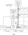
- Fig. 1 is a schematic structural diagram of a low-voltage power transmission system according to an embodiment of the present application. As shown in Fig. 1 , the low-voltage power transmission system 10 includes a DCDC converter 11 and a battery management system 12.
- the DCDC converter 11 may convert high-voltage power from a battery pack 20 into low-voltage power, and output the converted low-voltage power to a target low-voltage power consuming component.
- the DCDC converter 11 may perform self-awakening through a timer and awaken the BMS 12. Therefore, the battery pack 20 may be monitored using the battery management system 12 even when the target vehicle is in a power-off state.
- the DCDC converter 11 may include a timer. When the timer determines that a preset duration is reached, the DCDC converter 11 performs the self-awakening, sends an awakening signal to the BMS 12 after the self-awakening, and outputs low-voltage power to supply power the BMS 12.
- the BMS 12 can realize the function of monitoring the battery pack 20.
- the BMS 12 may collect battery pack state data such as a temperature of a single battery cell in the battery pack 20 and a voltage of a single battery cell in the battery pack 20, and determine whether the state of the battery pack 20 is abnormal on the basis of the battery pack state data.
- the BMS 12 can realize the function of controlling the DCDC converter 11.
- BMS 12 may be specifically implemented as a domain controller.
- the domain controller represents an electronic component with a vehicle control unit (Vehicle control unit, VCU) function, a motor control unit (Motor Control Unit, MCU) function, and a battery management system (Battery Management System, BMS) function integrated therein.
- VCU vehicle control unit
- MCU motor control unit
- BMS Battery Management System
- the domain controller may also have functions of other modules integrated therein, which will not be limited here.
- the low-voltage power transmission system 10 may further include a low-voltage power supply 13.
- the low-voltage power supply 13 may be a power supply device that can output a voltage of 12V or 24V, such as a lead-acid battery, which will not be specifically limited.
- a first switch module 14 is provided in a low-voltage power supply loop where the low-voltage power supply 13 is located.
- the low-voltage power supply loop between the low-voltage power supply 13 and the low-voltage power consuming modules is turned on, and the low-voltage power supply 13 can supply power to the low-voltage power modules.
- a low-voltage power supply loop between the low-voltage power supply 13 and the DCDC converter 11 is turned on, and the DCDC converter 11 can supplement power of the low-voltage power supply 13.
- the first switch module 14 may be specifically implemented as a manual switch.
- the position of the first switch module 14 may be set in other positions of the low-voltage power supply loop according to actual requirements or specific working scenarios, for example, the first switch module 14 may be set on a power supply loop where the DCDC converter 11 is located, which will not be limited here.
- the low-voltage power transmission system 10 may further include a state parameter transmitting apparatus 15.
- the battery management system 12 may transmit the state parameter of the battery pack 20 to a remote monitoring terminal through the state parameter transmitting apparatus 15.
- the state parameter of the battery pack 20 is for indicating the electrical characteristics states of the battery pack 20.
- the state parameters of the battery pack 20 may be voltage parameters of respective single battery cells in the battery pack 20 and/or temperature parameters of respective single battery cells in the battery pack 20.
- the state parameter transmitting apparatus 15 and the remote monitoring terminal may communicate wirelessly, for example, using a data transmission network such as the global system for mobile communications (Global System for Mobile Communications, GSM) network or the 4th generation mobile communication technology (the 4th generation mobile communication technology, 4G), or a wireless local area network such as wireless fidelity (Wireless Fidelity, Wi-Fi), which will not be particularly limited here.
- a data transmission network such as the global system for mobile communications (Global System for Mobile Communications, GSM) network or the 4th generation mobile communication technology (the 4th generation mobile communication technology, 4G), or a wireless local area network such as wireless fidelity (Wireless Fidelity, Wi-Fi), which will not be particularly limited here.
- GSM Global System for Mobile Communications
- 4G 4th generation mobile communication technology
- Wi-Fi wireless local area network
- the low-voltage power transmission system 10 may further include a second switch module 16 arranged in the low-voltage power supply loop.
- the second switch module 16 may be arranged on a low-voltage positive electrode power transmission line.
- the position of the second switch module 16 may be set according to specific scenarios and actual requirements, which will not be limited here. In an example, with continued reference to Fig. 1 , if a low-voltage power supply branch of each low-voltage power consuming component is connected to a same low-voltage power supply main line, then the second switch module 16 may be arranged on the low-voltage power supply main line. When the second switch module 16 is turned on, the low-voltage power consuming components may be powered.
- the low-voltage power supply branch may be connected to the low-voltage power supply loop between the DCDC converter 11 and the low-voltage power supply 13.
- the connecting point where the low-voltage power supply branch may be connected to the low-voltage power supply loop between the DCDC converter 11 and the low-voltage power supply 13 may be referred to as a first connecting point.
- the first switch module 14 may be arranged between the first connecting point and the low-voltage power supply 13. Therefore, when the target vehicle is in the power-off state, the second switch module 16 may be selectively turned on to supply power to the low-voltage power consuming modules, and the first switch module 14 may be turned on to supplement the power of the low-voltage power supply 13. This makes the low-voltage power transmission system 10 more flexible as a whole.
- the second switch module 16 may be turned on or off under the control by a vehicle controller 31.
- an enabling terminal of the vehicle controller 31 outputs a control signal for controlling the second switch module 16.
- the battery pack state of the vehicle in a power-off state can be monitored by proving only a DCDC converter 11 without providing a power distributing module. While the safety of the battery pack can be ensured, the topology and connection relationship of the low-voltage power transmission system can be simplified, and the wiring harness used by the low-voltage power transmission system can be reduced.
- the DCDC converter 11 After the introduction of the low-voltage power transmission system 10, the DCDC converter 11 will be specifically described in the following sections of the embodiments of the present application. For a thorough understanding of the DCDC converter 11, the control method, the apparatus, the device, and the medium according to the embodiments of the present application will be described in detail below with reference to the drawings. It should be noted that these embodiments are not used to limit the scope of the disclosure of the present application.
- Fig. 2 is a schematic flowchart of a control method according to an embodiment of the present application. As shown in Fig. 2 , the control method 200 according to this embodiments of the present application includes steps S110-S150.
- the charging signal is for indicating whether the vehicle is being charged.
- the above charging awaking signal may be referred to as an A+ signal.
- the charging signal is at a high level, and otherwise the charging signal is at a low level.
- a vehicle start signal is acquired.
- the vehicle start signal is for indicating whether the vehicle is powered on. If the vehicle start signal is at a high level, it is determined that the vehicle is powered on. Instead, if the vehicle start signal is at a low level, it is determined that the vehicle is not powered on.
- the vehicle start signal may be determined according to a gear position of an ignition switch of the target vehicle. For example, if the ignition switch of the target vehicle has been switched to a "key on" position, the vehicle start signal is at a high level. Otherwise, the vehicle start signal is at a low level. Accordingly, the vehicle start signal may be referred to as a key on signal.
- the enabling signal may be a signal sent by the BMS.
- the enabling signal can be called an ENABLE signal. If the enabling signal is at a high level, it indicates that output from the DCDC converter is allowed. In some embodiments, the enabling signal (ENABLE signal) may be received through an enabling port (ENABLE port) of the DCDC converter 11.
- the BMS 12 may perform communication through the communication line between the BMS 12 and the DCDC converter 11.
- the communication line includes a controller area network (Controller Area Network, CAN) bus or a serial communication line.
- the communication line may be a wireless communication line, which is not specifically limited here.
- the BMS 12 may send a CAN message to the DCDC converter 11.
- the information indicated by the CAN message needs to be consistent with the information indicated by the ENABLE signal.
- the ENABLE signal may be a high-level signal, and if the CAN message indicates that that the output from the DCDC converter is prohibited, the ENABLE signal may be a low-level signal.
- the CAN message may be taken as the main information source, and the fault is reported. If the CAN message is not received, that is, CANLOSS, the ENABLE signal may be used for the determination of the BMS 12 command.
- each of the charging signal, the vehicle start signal, and the enabling signal is at a low level and no communication message sent by the BMS 12 is received, it is determined that the vehicle is in a power-off state and enters a sleep mode.
- the self-awakening is performed on the DCDC converter 11 and the BMS 12 is awakened. It may be determined by a timer that the duration of the sleep mode reaches the preset duration.
- the preset duration in some embodiments, it may be set by the BMS 12 according to specific working scenarios and work needs. Accordingly, duration information sent by the BMS 12 that indicates the preset duration may be received. The preset duration may be adjusted according to the received duration information.
- the safety of the battery pack 20 may be affected because the BMS 12 cannot monitor the state parameter of the battery pack in real time. Therefore, in order to ensure the safety of the battery pack 20, when the target vehicle is in the power-off state, the DCDC converter 11 may be awakened periodically, thereby awakening the BMS 12 periodically. In this situation, after being awaken for a period of time, the BMS 12 re-enters the power-off mode from the working mode.
- the recorded time length may be cleared and the timing may be restarted.
- the preset duration needs to be longer than a single duration in which the BMS 12 is awakened.
- the BMS 12 re-enters the power-off mode, it will send a power-off prompt signal to the DCDC converter 11.
- the DCDC converter 11 receives the power-off prompt signal, it may clear the recorded time length and restart the timing.
- the awakening signal may be transmitted through a communication line.
- the awakening signal may be loaded in the CAN message.
- the BMS 12 may monitor the state parameters of the battery pack 20.
- the state parameter of the battery pack 20 is for indicating the state characteristics of the battery pack.
- the state parameter of the battery pack 20 may be voltage parameters of respective single battery cells in the battery pack 20 and/or temperature parameters of the respective single battery cells in the battery pack 20, a pressure parameter of the battery pack, a smoke parameter in the battery pack, and/or the like, which will not be specifically limited here.
- the BMS 12 because the BMS 12 is not powered on before being awakened, in order to successfully awaken the BMS 12, it is required to provide the BMS 12 with low-voltage power at the same time when awakening the BMS 12.
- the method further includes outputting a first power signal for supplying power to the BMS 12.
- the DCDC converter 11 may be in a low power output mode.
- the first power signal may be an output power, and the value of the first power signal may be equal to 300W.
- the DCDC converter when each of the charging signal, the vehicle start signal, and the enabling signal is at a low level and no communication message sent by the BMS 12 is received, it can be determined that the vehicle is in the power-off state and enters the sleep mode, and the self-awakening is performed when the duration of the sleep mode reaches the preset duration, and the awakening signal for awakening the BMS 12 and making the BMS 12 enter the working mode is outputted to the BMS 12. Therefore, the DCDC converter 11 can be used to awaken the battery management system to monitor the battery pack, so that the BMS 12 can also be used to monitor the safety state of the vehicle after the vehicle is powered off, thereby improving the safety of the battery pack 20.
- a charging state may also be determined.
- the charging state will be explained in the following section in detail.
- the method 200 further includes the following step.
- the DCDC converter 11 may further output a second power signal.
- the method 200 further includes outputting the second power signal.
- the second power signal is determined according to power demand of a target power consuming module.
- the DCDC converter 11 may output a constant voltage, for example, a voltage intensity value of the constant voltage may be 27V.
- the voltage intensity value of the second power signal may be in a range of 0-3KW.
- Case (1) the low-voltage power supply loop including the low-voltage power supply 13 and the DCDC converter 11 is turned off.
- this case may specifically be where the first switch module 14 is turned off.
- the DCDC converter 11 is required to supply power to the low voltage consuming component.
- the low-voltage power consuming component includes the BMS 12.
- the voltage intensity value of the second power signal may vary within the range of 300W-3KW.
- Case (2) when the above-mentioned low-voltage power supply loop is turned on and the output voltage of the low-voltage power supply is less than or equal to the output voltage of the DCDC converter 11, the DCDC converter 11 is required to supply power to the low-voltage power supply 13 and the low-voltage power consuming components.
- the target power consuming modules include the low-voltage power supply 13 and the low-voltage power consuming components.
- Case (3) when the above low-voltage power supply loop is turned on and the output voltage of the low-voltage power supply is greater than the output voltage of the DCDC converter 11, the low-voltage power supply 13 meets the power demand of the target power consuming module, that is, the low-voltage power supply supplies power to the target power consuming module, and in this situation, the power demand of the target power consuming module on the DCDC converter 11 is zero, and the voltage intensity value of the second power signal is equal to zero.
- a traveling state in addition to using the above four signals to determine the power-off state, a traveling state can also be determined.
- the traveling state will be explained in the following section in detail.
- the method 200 further includes: under a condition that the charging signal is at a low level, the vehicle start signal is at a high level, and the first communication message is received, determining that the vehicle is in the traveling state; or, under a condition that the charging signal is at a low level, the vehicle start signal and the enable signal are at a high level, and the communication message is not received, determining that the vehicle is in the traveling state.
- the method 200 further includes the following step: outputting a third power signal is outputted.
- the content of the third power signal is similar to that of the second power signal, and will not be repeated here.
- a standby state may also be determined.
- the standby state will be explained in the following section in detail.
- the method 200 further includes: under a condition that the first communication message is received and the charging signal and the vehicle start signal are at a high level, determining that the vehicle is in the standby state; or, under a condition that the second communication message is received, determining that the vehicle is in the standby state.
- the CAN message indicates that the output from the DCDC converter 11 is prohibited, and it can be determined that the vehicle is in the standby state regardless of the levels of the A+ signal, the KEY ON signal, and the ENABLE signal; (2) when CANLOSS, the A+ signal and the ENABLE signal are at a low level and the KEY ON signal is at a high level, it is determined that the vehicle is in the standby state.
- the DCDC converter 11 when the DCDC converter 11 is in the standby mode, its output power is 0, that is, no power is outputted.
- the standby mode ends when the conditions of other states are met.
- the vehicle in addition to using the above four signals to determine the power-off state, it may also be determined that the vehicle is in a target state indicating that the vehicle is ready to enter the sleep mode.
- the target state will be explained in the following section in detail.
- the method 200 further includes: when the first communication message is received and the charging signal and the vehicle start signal are at a low level, determining that the vehicle is in a target state in which the vehicle is waiting to enter the sleep mode.
- the vehicle when the vehicle is not ignited and the vehicle is not charged, the vehicle may be in the target state in which the vehicle is waiting to enter the sleep mode because the BMS 12 has not been completely powered off.
- the DCDC converter 11 stops output, that is, the output voltage and output power of the DCDC converter 11 may be equal to zero.
- the vehicle in addition to using the above four signals to determine the power-off state, it may also be determined that the vehicle is in the fault state.
- the fault state will be explained in the following section in detail.
- the method 200 further includes: when no communication message sent by the BMS 12 is received, the charging signal and the vehicle start signal are at a low level, and the enabling signal is at a high level, determining that the vehicle is in a fault state.
- the Enable signal is at a high level in the fault state
- the DCDC converter is in a self-awakening abnormal state and cannot enter the sleep state, the fault is reported to the BMS 12, and no power is outputted.
- each of the A+ signal and KEY ON signal is at a low level and the ENABLE signal is at a high level, it can be determined that the vehicle is in the fault state.
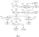
- FIG. 3 is a schematic flowchart of an exemplary control method according to an embodiment of the present application.
- S303 it is determined whether the KEY ON signal is a high-level signal. If the determination result is positive, S304 is performed; if the determination result is negative, S305, S306 or S307 is performed.
- the first condition is that the ENABLE signal is at a low level and CANLOSS, or the second CAN message is received. If the determination result is positive, it is determined that the vehicle is in the standby state; if the determination result is negative, it is determined that the vehicle is in the traveling state.
- the embodiments of the present application further provide a corresponding DCDC converter.
- the apparatus according to the embodiments of the present application will be described in detail with reference to the drawings.
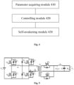
- Fig. 4 is a schematic structural diagram of a DCDC converter according to an embodiment of the present application.
- the DCDC converter apparatus includes a parameter acquiring module 410, a controlling module 420, and a self-awakening module 430.
- the parameter acquiring module 410 is configured to acquire a charging signal, a vehicle start signal, and an enabling signal.
- the control module 420 is configured to determine that a vehicle is in a power-off state and enters a sleep mode when each of the charging signal, the vehicle start signal, and the enabling signal is at a low level, and no communication message sent by a battery management system (BMS) is received.
- BMS battery management system
- the self-awakening module 430 is configured to perform self-awakening and output, to the BMS, an awakening signal for awakening the BMS and making the BMS enter a working mode, when a duration of the sleep mode reaches a preset duration.
- the DCDC converter apparatus further includes: a first outputting module configured to output a first power signal for supplying power to the BMS.
- the DCDC converter apparatus further includes: a state determining module configured to determine that the vehicle is in a charging state, under a condition that the charging signal is at a high level, when the first communication message is received or the communication message is not received.
- the DCDC converter apparatus further includes: a second outputting module configured to output a second power signal determined according to power demand of a target power consuming module.
- the DCDC converter supplies power to the target power consuming module through the second power signal, the target power consuming module includes a low-voltage power consuming component, and the low-voltage power consuming component includes the BMS.
- the target power consuming module includes the low-voltage power supply and the low-voltage power consuming component.
- the power demand of the target power consuming module is zero and the second power signal is equal to zero.
- the DCDC converter supplies power through the second power signal to the target power consuming module that includes the low-voltage power supply and the low-voltage power consuming component.
- the DCDC converter apparatus further includes: a state determining module configured to determine that the vehicle is in a traveling state, when the charging signal is at a low level, the vehicle start signal is at a high level, and the first communication message is received, or when the charging signal is at a low level, the vehicle start signal and the enable signal are at a high level, and the communication message is not received.
- a state determining module configured to determine that the vehicle is in a traveling state, when the charging signal is at a low level, the vehicle start signal is at a high level, and the first communication message is received, or when the charging signal is at a low level, the vehicle start signal and the enable signal are at a high level, and the communication message is not received.
- the DCDC converter apparatus further includes: a third outputting module configured to output a third power signal determined according to power demand of a target power consuming module.
- a third outputting module configured to output a third power signal determined according to power demand of a target power consuming module.
- the target power consuming module includes the low-voltage power supply and the low-voltage power consuming component.
- the power demand of the target power consuming module is zero and the third power signal is equal to zero.
- the DCDC converter supplies power through the third power signal to the target power consuming module that includes the low-voltage power supply and the low-voltage power consuming component.
- the DCDC converter apparatus further includes: a state determining module configured to determine that the vehicle is in a standby state, when the first communication message is received and the charging signal and the vehicle start signal are at a high level, or when the second communication message is received.
- the DCDC converter apparatus further includes: a state determining module configured to determine that the vehicle is in a target state in which the vehicle is waiting to enter the sleep mode, when the first communication message is received and the charging signal and the vehicle start signal are at a low level.
- the DCDC converter apparatus further includes: a state determining module configured to determine that the vehicle is in a fault state, when no communication message sent by the BMS 12 is received, the charging signal and the vehicle start signal are at a low level, and the enabling signal is at a high level.
- the DCDC converter includes a phase-shifted full-bridge circuit.
- the embodiments of the present application illustrate an exemplary phase-shifting full-bridge converter (Phase-Shifting Full-Bridge Converter, PSFB) unit with reference to Fig. 5 .
- PSFB Phase-Shifting Full-Bridge Converter
- the circuit in Fig. 5 is the main power topology structure of the DCDC controller provided by the embodiments of the present application.
- a phase-shifted full bridge (PSFB) is used at the primary side of the DCDC controller.
- Q1-Q4 are four sic-metal-oxide-semiconductor (SiC-Metal-Oxide-Semiconductor, SiC-MOS) switch tubes.
- Junction capacitors C1, C2, C3 and C4 a transformer leakage inductance C b and a resonance inductance Lr are used in Q1-Q4 as resonance elements to turn on and off the four SiC-MOS switch tubes sequentially at zero voltage (ZVS) so as to realize soft switching.
- ZVS zero voltage
- the clamp diode Dc1 and clamp diode Dc2 are used to suppress the voltage oscillation of the secondary side, a direct current blocking capacitor Cb is connected in series to suppress the direct current component in the high-frequency transformer primary winding, and the secondary side adopts a full-wave rectification scheme using synchronous rectification technology, which improves the conversion efficiency of the DCDC converter.
- vin is an input direct current power supply.
- D1-D4 are parasitic diodes or additional freewheeling diodes of the four switch tubes.
- Tr is a phase-shifted full-bridge power transformer.
- Qs 1 and Qs 2 are switch tubes.
- L f is a secondary output freewheeling inductor of the phase-shifted full-bridge power supply.
- C f is a secondary output capacitance of the phase-shifted full-bridge power supply.
- R Ld is a secondary load of the phase-shifted full-bridge power supply.
- the DCDC converter in the embodiments of the present application, when each of the charging signal, the vehicle start signal, and the enable signal is at a low level and no communication message sent by the BMS is received, it can be determined that the vehicle is in a power-off state and enters the sleep mode.
- the duration of the sleep mode reaches the preset duration, the self-awakening is performed, and the awakening signal for awakening the BMS and making the BMS enter the working mode is outputted to the BMS. Therefore, the DCDC converter can be used to awaken the battery management system for monitoring the battery pack, so that the safety state of the vehicle can be monitored using the battery management system when the vehicle is powered off, which improves the safety of the battery pack.
- the DCDC converter 11 can be self-awakened and enter the working mode, and there is no need to provide a vehicle DCDC relay between the DCDC and the battery pack, which simplifies the circuit structure.
- Fig. 6 illustrates a schematic structural diagram of hardware of a control device according to an embodiment of the present application.
- the control device may include a processor 601 and a memory 602 having computer program instructions stored thereon.
- the above-mentioned processor 601 may include a central processing unit (Central Processing Unit, CPU), or an application specific integrated circuit (Application Specific Integrated Circuit, ASIC), or one or more integrated circuits that may be configured to implement of the embodiments of the present application.
- CPU Central Processing Unit
- ASIC Application Specific Integrated Circuit
- the memory 602 may include a mass memory for data or instructions.
- the memory 602 may include a hard disk drive (Hard Disk Drive, HDD), a floppy disk drive, a flash memory, an optical disk, a magneto-optical disk, a magnetic tape or a universal serial bus (Universal Serial Bus, USB) drive, or a combination of two or more of them.
- the memory 602 may include removable or non-removable (or fixed) media, or the memory 602 may be a non-volatile solid-state memory.
- the memory 602 may be internal or external to the control device.
- the memory 602 may be a read only memory (Read Only Memory, ROM).
- ROM Read Only Memory
- the ROM may be a mask-programmed ROM, a programmable ROM (PROM), an erasable PROM (EPROM), an electrically erasable PROM (EEPROM), an electrically rewritable ROM (EAROM) or flash memory, or a combination of two or more of them.
- the memory 602 may include a read-only memory (ROM), a random access memory (RAM), a magnetic disk storage media device, an optical storage media devices, a flash memory device, an electrical, optical, or other physical/tangible memory storage device. Therefore, generally, the memory may include one or more tangible (non-transitory) computer-readable storage media (e.g., memory devices) encoded with software including computer-executable instructions, and when the software is executed (e.g., by one or more processors), it is operable to perform operations described with reference to the method according to an aspect of the present disclosure.
- the processor 601 reads and executes the computer program instructions stored in the memory 602, to implement the methods in the embodiments shown in Fig. 2 to Fig. 3 , and achieve corresponding technical effects achieved when the methods of the embodiments shown in Fig. 2 to Fig. 3 are executed, which will not be repeated here, for concision of the description.
- control device may further include a communication interface 603 and a bus 610. As shown in Fig. 6 , the processor 601, the memory 602, and the communication interface 603 are connected and communicate with one another through the bus 610.
- the communication interface 603 is mainly used to implement communications between various modules, apparatuses, units and/or devices in the embodiments of the present application.
- the bus 610 may include hardware, software, or both, and couple components of an online data flow accounting device to each other.
- the bus may include an accelerated graphics port (Accelerated Graphics Port, AGP) or other graphics bus, an enhanced industry standard architecture (Extended Industry Standard Architecture, EISA) bus, a front side bus (Front Side Bus, FSB), a hyper transport (Hyper Transport, HT) interconnection, an industry standard architecture (Industry Standard Architecture, ISA) bus, an unlimited bandwidth interconnection, a low pin count (LPC) bus, a memory bus, a microchannel architecture (MCA) bus, a peripheral component interconnection PCI bus, a PCI-Express (PCI-X) bus, a Serial Advanced Technology Attachment (SATA) bus, a Video Electronics Standards Association Local (VLB) bus or other suitable bus or a combination of two or more of them.
- the bus 610 may include one or more buses.
- the control device can execute the control method in the embodiment of the present application, so as to realize the control method and control apparatus described in conjunction with Fig. 1 to Fig. 5 .
- the embodiments of the present application may provide a computer storage medium to implement the method.
- the computer storage medium has computer program instructions stored thereon. When the computer program instructions are executed by the processor, any control method in the aforementioned embodiment can be implemented.
Landscapes
- Engineering & Computer Science (AREA)
- Power Engineering (AREA)
- Mechanical Engineering (AREA)
- Transportation (AREA)
- Sustainable Energy (AREA)
- Sustainable Development (AREA)
- Life Sciences & Earth Sciences (AREA)
- Software Systems (AREA)
- Theoretical Computer Science (AREA)
- Physics & Mathematics (AREA)
- Chemical Kinetics & Catalysis (AREA)
- General Chemical & Material Sciences (AREA)
- General Engineering & Computer Science (AREA)
- General Physics & Mathematics (AREA)
- Electrochemistry (AREA)
- Chemical & Material Sciences (AREA)
- Manufacturing & Machinery (AREA)
- Microelectronics & Electronic Packaging (AREA)
- Charge And Discharge Circuits For Batteries Or The Like (AREA)
- Electric Propulsion And Braking For Vehicles (AREA)
- Dc-Dc Converters (AREA)
Description
- This application relates to the field of battery technology, and in particular to a low-voltage power transmission system, a low-voltage power transmission system, a DCDC converter, and a control method, a device, and a medium.
- With the development of new energy, it has been adopted as power sources in more and more fields. Batteries are widely used in new energy vehicles, consumer electronics, and energy storage systems due to their advantages of high energy density, cycle chargeability, high safety, and being environmental friendly.
- With the development of new energy, battery safety issues have gradually attracted public attention. However, at present, the battery pack cannot be monitored after the vehicle is powered off, so that the safety of the vehicle cannot be guaranteed after it is powered off, especially the safety issues such as battery fire and explosion cannot be prevented in time.
- Document
CN110861530A discloses a monitoring system for a power battery, including a battery control unit (BCU), a battery management unit (BMU), a storage battery, a TBOX, a DCDC converter and a power battery, wherein the output end of the power battery is connected with the DCDC converter, and the power supply output end of the DCDC converter is connected with the power supply input end of the BCU, the power supply input end of the TBOX and the enable wake-up input end of the BCU, and the power supply output end of the storage battery is connected with the BCU and the TBOX through a rocker switch; the BCU is connected with the BMU, the DCDC converter and the TBOX through CAN communication; and the high-side driving output end of the BCU is connected with the driving input end of the DCDC converter. DocumentCN110641284A relates to a low-voltage power supply management system for monitoring the power battery of an electric vehicle, in which a battery management system is utilized for achieving real-time monitoring or intermittent monitoring on vehicle state information which mainly comprises a high-voltage state in a high-voltage box and a power battery pack state; when the vehicle is in the traveling state, the DCDC converter does not output any power. - The invention is set out in the appended set of claims.
- The drawings necessary for explaining embodiments are introduced briefly below to illustrate the technical solutions of the embodiments of the present application more clearly. Apparently, the drawings described below are merely some embodiments of the present application. Other figures can be obtained by those with ordinary skill in the art from those drawings without any creative work.
-
Fig. 1 is a schematic structural diagram of a low-voltage power transmission system according to an embodiment of the present application. -
Fig. 2 is a schematic flowchart of a control method according to an embodiment of the present application. -
Fig. 3 is a schematic flowchart of an exemplary control method according to an embodiment of the present application. -
Fig. 4 is a schematic structural diagram of a DCDC converter according to an embodiment of the present application. -
Fig. 5 is a schematic structural diagram of an exemplary phase-shifting full-bridge unit according to an embodiment of the present application. -
Fig. 6 is a structural diagram of an exemplary hardware architecture of a control device according to an embodiment of the present application. - The drawings are not drawn to actual scale.
- It is to be noted that relational terms such as first, second, and the like are used herein solely to distinguish one entity or operation from another entity or operation without necessarily requiring or implying any actual such relationship or order between such entities or operations. Moreover, the terms "include", "including", or any other variation thereof, are intended to cover a non-exclusive inclusion, such that a process, method, article or device that includes a series of elements does not include only those elements but may include other elements not explicitly listed or inherent to such process, method, article or device. An element preceded by "include... " does not, without more constraints, preclude the existence of additional identical elements in the process, method, article or device that includes the element.
- A power supply in an electric vehicle may include a high-voltage battery pack and a low-voltage power supply. The high-voltage battery pack may include at least one battery module or at least one battery cell, which is not limited here. The high-voltage battery pack may be used as the power source of the electric vehicle to supply power to a motor. The low-voltage power supply may provide 12V or 24V low-voltage power for low-voltage power consuming components in the vehicle. In an example, the low-voltage power supply may be a lead-acid battery. The low-voltage power consuming components may be instrument controllers, relays, air pump controllers and the like in the vehicle that need to be driven by low-voltage.
- In practical use, the electric vehicle may be in different use states, for example, a traveling state, a charging state, or a power-off state. When the vehicle is in a driving scene, the electric vehicle is in the traveling state. At this time, the vehicle needs to be in a power-on state. In other words, the low-voltage power consuming components of the vehicle need to be energized. At this time, it is required to use a low-voltage power supply or a direct current-direct current (Direct Current- Direct Current, DCDC) converter to supply power to the low-voltage power consuming components. In a scene where the vehicle is being charged, if low-voltage power consuming components in the vehicle are all powered off, the vehicle is in a power-off and charging state. If the low-voltage power consuming components in the vehicle are powered on, the vehicle is in a power-on and charging state. In addition, in a vehicle braking and parking scene, after the vehicle comes to a complete stop and the low-voltage power consuming components in the vehicle are all powered off, the vehicle is in a vehicle power-off state.
- Currently, when the vehicle is in the power-on state, the state of the battery pack may be monitored using a battery management system. After the vehicle is powered off, the battery management system will also be powered off, and the state of the battery pack cannot be monitored. If the state of the battery pack is abnormal at this time, the abnormality cannot be discovered in time and corrective measures cannot be taken in time, so that the safety of the battery pack cannot be ensured.
- Therefore, there is a lack of a technical solution that can awaken a battery management system (battery Management System, BMS) to make the BMS enter a working mode when the vehicle is powered off so that the battery safety is ensured.
-
Fig. 1 is a schematic structural diagram of a low-voltage power transmission system according to an embodiment of the present application. As shown inFig. 1 , the low-voltagepower transmission system 10 includes aDCDC converter 11 and abattery management system 12. - Regarding the
DCDC converter 11, it may convert high-voltage power from abattery pack 20 into low-voltage power, and output the converted low-voltage power to a target low-voltage power consuming component. - When the target vehicle is in a power-off state, the DCDC
converter 11 may perform self-awakening through a timer and awaken the BMS 12. Therefore, thebattery pack 20 may be monitored using thebattery management system 12 even when the target vehicle is in a power-off state. In an example, theDCDC converter 11 may include a timer. When the timer determines that a preset duration is reached, theDCDC converter 11 performs the self-awakening, sends an awakening signal to theBMS 12 after the self-awakening, and outputs low-voltage power to supply power theBMS 12. - Regarding the
BMS 12, it can realize the function of monitoring thebattery pack 20. For example, theBMS 12 may collect battery pack state data such as a temperature of a single battery cell in thebattery pack 20 and a voltage of a single battery cell in thebattery pack 20, and determine whether the state of thebattery pack 20 is abnormal on the basis of the battery pack state data. In addition, theBMS 12 can realize the function of controlling theDCDC converter 11. - It should be noted that BMS 12 may be specifically implemented as a domain controller. The domain controller represents an electronic component with a vehicle control unit (Vehicle control unit, VCU) function, a motor control unit (Motor Control Unit, MCU) function, and a battery management system (Battery Management System, BMS) function integrated therein. The domain controller may also have functions of other modules integrated therein, which will not be limited here.
- In some embodiments, with continued reference to
Fig. 1 , the low-voltagepower transmission system 10 may further include a low-voltage power supply 13. In an example, the low-voltage power supply 13 may be a power supply device that can output a voltage of 12V or 24V, such as a lead-acid battery, which will not be specifically limited. - In an example, a
first switch module 14 is provided in a low-voltage power supply loop where the low-voltage power supply 13 is located. When thefirst switch module 14 is turned on, the low-voltage power supply loop between the low-voltage power supply 13 and the low-voltage power consuming modules is turned on, and the low-voltage power supply 13 can supply power to the low-voltage power modules. At the same time, a low-voltage power supply loop between the low-voltage power supply 13 and theDCDC converter 11 is turned on, and theDCDC converter 11 can supplement power of the low-voltage power supply 13. In an example, thefirst switch module 14 may be specifically implemented as a manual switch. - It should be noted that, the position of the
first switch module 14 may be set in other positions of the low-voltage power supply loop according to actual requirements or specific working scenarios, for example, thefirst switch module 14 may be set on a power supply loop where theDCDC converter 11 is located, which will not be limited here. - In some embodiments, with continued reference to
Fig. 1 , the low-voltagepower transmission system 10 may further include a state parameter transmitting apparatus 15. After a state parameter of thebattery pack 20 is acquired by thebattery management system 12, thebattery management system 12 may transmit the state parameter of thebattery pack 20 to a remote monitoring terminal through the state parameter transmitting apparatus 15. The state parameter of thebattery pack 20 is for indicating the electrical characteristics states of thebattery pack 20. For example, the state parameters of thebattery pack 20 may be voltage parameters of respective single battery cells in thebattery pack 20 and/or temperature parameters of respective single battery cells in thebattery pack 20. In an example, the state parameter transmitting apparatus 15 and the remote monitoring terminal may communicate wirelessly, for example, using a data transmission network such as the global system for mobile communications (Global System for Mobile Communications, GSM) network or the 4th generation mobile communication technology (the 4th generation mobile communication technology, 4G), or a wireless local area network such as wireless fidelity (Wireless Fidelity, Wi-Fi), which will not be particularly limited here. - In some embodiments, the low-voltage
power transmission system 10 may further include asecond switch module 16 arranged in the low-voltage power supply loop. Specifically, thesecond switch module 16 may be arranged on a low-voltage positive electrode power transmission line. The position of thesecond switch module 16 may be set according to specific scenarios and actual requirements, which will not be limited here. In an example, with continued reference toFig. 1 , if a low-voltage power supply branch of each low-voltage power consuming component is connected to a same low-voltage power supply main line, then thesecond switch module 16 may be arranged on the low-voltage power supply main line. When thesecond switch module 16 is turned on, the low-voltage power consuming components may be powered. - In addition, the low-voltage power supply branch may be connected to the low-voltage power supply loop between the
DCDC converter 11 and the low-voltage power supply 13. The connecting point where the low-voltage power supply branch may be connected to the low-voltage power supply loop between theDCDC converter 11 and the low-voltage power supply 13 may be referred to as a first connecting point. Thefirst switch module 14 may be arranged between the first connecting point and the low-voltage power supply 13. Therefore, when the target vehicle is in the power-off state, thesecond switch module 16 may be selectively turned on to supply power to the low-voltage power consuming modules, and thefirst switch module 14 may be turned on to supplement the power of the low-voltage power supply 13. This makes the low-voltagepower transmission system 10 more flexible as a whole. - In addition, the
second switch module 16 may be turned on or off under the control by avehicle controller 31. In an example, an enabling terminal of thevehicle controller 31 outputs a control signal for controlling thesecond switch module 16. - With the low-voltage
power transmission system 10 according to this embodiment of the present application, the battery pack state of the vehicle in a power-off state can be monitored by proving only aDCDC converter 11 without providing a power distributing module. While the safety of the battery pack can be ensured, the topology and connection relationship of the low-voltage power transmission system can be simplified, and the wiring harness used by the low-voltage power transmission system can be reduced. - After the introduction of the low-voltage
power transmission system 10, theDCDC converter 11 will be specifically described in the following sections of the embodiments of the present application. For a thorough understanding of theDCDC converter 11, the control method, the apparatus, the device, and the medium according to the embodiments of the present application will be described in detail below with reference to the drawings. It should be noted that these embodiments are not used to limit the scope of the disclosure of the present application. -
Fig. 2 is a schematic flowchart of a control method according to an embodiment of the present application. As shown inFig. 2 , thecontrol method 200 according to this embodiments of the present application includes steps S110-S150. - At S 110, a charging signal is acquired.
- The charging signal is for indicating whether the vehicle is being charged. For example, the above charging awaking signal may be referred to as an A+ signal. Specifically, if a 12V or 24V low-voltage signal is inputted from an external charging power source such as a charging gun, the charging signal is at a high level, and otherwise the charging signal is at a low level.
- At S120, a vehicle start signal is acquired.
- The vehicle start signal is for indicating whether the vehicle is powered on. If the vehicle start signal is at a high level, it is determined that the vehicle is powered on. Instead, if the vehicle start signal is at a low level, it is determined that the vehicle is not powered on. In an example, the vehicle start signal may be determined according to a gear position of an ignition switch of the target vehicle. For example, if the ignition switch of the target vehicle has been switched to a "key on" position, the vehicle start signal is at a high level. Otherwise, the vehicle start signal is at a low level. Accordingly, the vehicle start signal may be referred to as a key on signal.
- At S130, an enabling signal is acquired.
- The enabling signal may be a signal sent by the BMS. The enabling signal can be called an ENABLE signal. If the enabling signal is at a high level, it indicates that output from the DCDC converter is allowed. In some embodiments, the enabling signal (ENABLE signal) may be received through an enabling port (ENABLE port) of the
DCDC converter 11. - In addition, in addition to sending the enable signal to the
DCDC converter 11, theBMS 12 may perform communication through the communication line between theBMS 12 and theDCDC converter 11. The communication line includes a controller area network (Controller Area Network, CAN) bus or a serial communication line. Alternatively, the communication line may be a wireless communication line, which is not specifically limited here. For example, if the communication line between theBMS 12 and theDCDC converter 11 is a CAN bus, theBMS 12 may send a CAN message to theDCDC converter 11. - Specifically, under normal conditions, the information indicated by the CAN message needs to be consistent with the information indicated by the ENABLE signal. In an example, if the CAN message indicates that the output from the
DCDC converter 11 is allowed, the ENABLE signal may be a high-level signal, and if the CAN message indicates that that the output from the DCDC converter is prohibited, the ENABLE signal may be a low-level signal. In an example, if the information indicated by the CAN message is inconsistent with that indicated by the ENABLE signal, then the CAN message may be taken as the main information source, and the fault is reported. If the CAN message is not received, that is, CANLOSS, the ENABLE signal may be used for the determination of theBMS 12 command. - It should also be noted that, the embodiments of the present application does not limit the execution sequence of S110, S120, and S130, and these steps may be executed synchronously or asynchronously.
- At S140, if each of the charging signal, the vehicle start signal, and the enabling signal is at a low level and no communication message sent by the
BMS 12 is received, it is determined that the vehicle is in a power-off state and enters a sleep mode. - At S150, when a duration of the sleep mode reaches a preset duration, self-awakening is performed, and an awaking signal for awakening the BMS and making the BMS enter a working mode is outputted to the BMS.
- That is to say, when the vehicle is in the sleep mode and the duration of the sleep mode reaches a preset duration, the self-awakening is performed on the
DCDC converter 11 and theBMS 12 is awakened. It may be determined by a timer that the duration of the sleep mode reaches the preset duration. - Regarding the preset duration, in some embodiments, it may be set by the
BMS 12 according to specific working scenarios and work needs. Accordingly, duration information sent by theBMS 12 that indicates the preset duration may be received. The preset duration may be adjusted according to the received duration information. - In some embodiments, if the
BMS 12 is in a continuous power-off mode because the target vehicle is in the power-off state, when the target vehicle is in the power-off state, the safety of thebattery pack 20 may be affected because theBMS 12 cannot monitor the state parameter of the battery pack in real time. Therefore, in order to ensure the safety of thebattery pack 20, when the target vehicle is in the power-off state, theDCDC converter 11 may be awakened periodically, thereby awakening theBMS 12 periodically. In this situation, after being awaken for a period of time, theBMS 12 re-enters the power-off mode from the working mode. - In an example, in order to realize the periodic self-awakening of the
DCDC converter 11, after theDCDC converter 11 outputs the awakening signal to theBMS 12, the recorded time length may be cleared and the timing may be restarted. In this situation, the preset duration needs to be longer than a single duration in which theBMS 12 is awakened. Alternatively, after theBMS 12 re-enters the power-off mode, it will send a power-off prompt signal to theDCDC converter 11. After theDCDC converter 11 receives the power-off prompt signal, it may clear the recorded time length and restart the timing. - Further, for the awakening signal, the awakening signal may be transmitted through a communication line. In an example, the awakening signal may be loaded in the CAN message.
- In addition, it should be noted that, after the
BMS 12 enters the working mode, theBMS 12 may monitor the state parameters of thebattery pack 20. The state parameter of thebattery pack 20 is for indicating the state characteristics of the battery pack. For example, the state parameter of thebattery pack 20 may be voltage parameters of respective single battery cells in thebattery pack 20 and/or temperature parameters of the respective single battery cells in thebattery pack 20, a pressure parameter of the battery pack, a smoke parameter in the battery pack, and/or the like, which will not be specifically limited here. - In some embodiments, because the
BMS 12 is not powered on before being awakened, in order to successfully awaken theBMS 12, it is required to provide theBMS 12 with low-voltage power at the same time when awakening theBMS 12. - Accordingly, after the self-awakening is performed under a condition that the duration of the sleep mode reaches the preset duration, the method further includes outputting a first power signal for supplying power to the
BMS 12. In an example, theDCDC converter 11 may be in a low power output mode. For example, the first power signal may be an output power, and the value of the first power signal may be equal to 300W. - According to the low-voltage power transmission system, the DCDC converter, the control method, the device, and the medium in the embodiments of the present application, when each of the charging signal, the vehicle start signal, and the enabling signal is at a low level and no communication message sent by the
BMS 12 is received, it can be determined that the vehicle is in the power-off state and enters the sleep mode, and the self-awakening is performed when the duration of the sleep mode reaches the preset duration, and the awakening signal for awakening theBMS 12 and making theBMS 12 enter the working mode is outputted to theBMS 12. Therefore, theDCDC converter 11 can be used to awaken the battery management system to monitor the battery pack, so that theBMS 12 can also be used to monitor the safety state of the vehicle after the vehicle is powered off, thereby improving the safety of thebattery pack 20. - According to the embodiments of the present application, in addition to using the above four signals to determine the power-off state, a charging state may also be determined. The charging state will be explained in the following section in detail.
- In some embodiments, if the communication message includes a first communication message allowing output from the DCDC converter and a second communication message prohibiting output from the DCDC converter, the
method 200 further includes the following step. - Under a condition that the charging signal is at a high level, when the first communication message is received or the communication message is not received, determining that the vehicle is in a charging state. No communication message being received means that no first communication message and no second communication message is received.
- In an example, it may be determined that the vehicle is in the charging state under the eight conditions listed in Table 1.
Table 1 CAN A+ KEY ON ENABLE Vehicle state (1) Output allowed High High High Charging (2) Output allowed High High Low Charging (3) Output allowed High Low High Charging (4) Output allowed High Low Low Charging (5) LOSS High High High Charging (6) LOSS High High Low Charging (7) LOSS High Low High Charging (8) LOSS High Low Low Charging - As shown in Table 1, (1) when the CAN message indicates that the output from the DCDC converter 11 is allowed, and each of the A+ signal, the KEY ON signal, and the ENABLE signal is at a high level, it is determined that the vehicle is in the charging state; (2) when the CAN message indicates that the output from the DCDC converter 11 is allowed, the A+ signal and the KEY ON signal are at a high level, and the ENABLE signal is at a low level, it is determined that the vehicle is in the charging state; (3) when the CAN message indicates that the output from the DCDC converter 11 is allowed, the A+ signal and the ENABLE signal are at a high level, and the KEY ON signal is at a low level, it is determined that the vehicle is in the charging state; (4) when the CAN message indicates that the output from the DCDC converter 11 is allowed, the A+ signal is at a high level, and the KEY ON signal and the ENABLE signal are at a low level, it is determined that the vehicle is in the charging state; (5) when no CAN message is received, that is, CANLOSS, and each of the A+ signal, the KEY ON signal, and the ENABLE signal is at a high level, it is determined that the vehicle is in the charging state; (6) when CANLOSS, the A+ signal and the KEY ON signal are at a high level and the ENABLE signal is at a low level, it is determined that the vehicle is in the charging state; (7) when CANLOSS, the A+ signal and the ENABLE signal are at a high level and the KEY ON signal is at a low level, it is determined that the vehicle is in the charging state; (8) when CANLOSS, the A+ signal is at a high level and the KEY ON signal and the ENABLE signal are at a low level, it is determined that the vehicle is in the charging state.
- In some embodiments, in the charging state, the
DCDC converter 11 may further output a second power signal. Correspondingly, after determining that the vehicle is in the charging state, themethod 200 further includes outputting the second power signal. - The second power signal is determined according to power demand of a target power consuming module. In an example, the
DCDC converter 11 may output a constant voltage, for example, a voltage intensity value of the constant voltage may be 27V. However, the voltage intensity value of the second power signal may be in a range of 0-3KW. - Specifically, there are three cases for the second power signal.
- Case (1): the low-voltage power supply loop including the low-voltage power supply 13 and the
DCDC converter 11 is turned off. In an example, with reference toFig. 1 , this case may specifically be where thefirst switch module 14 is turned off. In this situation, theDCDC converter 11 is required to supply power to the low voltage consuming component. The low-voltage power consuming component includes theBMS 12. In an example, the voltage intensity value of the second power signal may vary within the range of 300W-3KW. - Case (2): when the above-mentioned low-voltage power supply loop is turned on and the output voltage of the low-voltage power supply is less than or equal to the output voltage of the
DCDC converter 11, theDCDC converter 11 is required to supply power to the low-voltage power supply 13 and the low-voltage power consuming components. In this situation, the target power consuming modules include the low-voltage power supply 13 and the low-voltage power consuming components. - Case (3): when the above low-voltage power supply loop is turned on and the output voltage of the low-voltage power supply is greater than the output voltage of the
DCDC converter 11, the low-voltage power supply 13 meets the power demand of the target power consuming module, that is, the low-voltage power supply supplies power to the target power consuming module, and in this situation, the power demand of the target power consuming module on theDCDC converter 11 is zero, and the voltage intensity value of the second power signal is equal to zero. - In the embodiments of the present application, in addition to using the above four signals to determine the power-off state, a traveling state can also be determined. The traveling state will be explained in the following section in detail.
- According to the invention, the
method 200 further includes: under a condition that the charging signal is at a low level, the vehicle start signal is at a high level, and the first communication message is received, determining that the vehicle is in the traveling state; or, under a condition that the charging signal is at a low level, the vehicle start signal and the enable signal are at a high level, and the communication message is not received, determining that the vehicle is in the traveling state. - In an example, it can be determined that the vehicle is in the traveling state under the three conditions shown in Table 2.
Table 2 CAN A+ KEY ON ENABLE Vehicle state (1) Output allowed Low High High Traveling (2) Output allowed Low High Low Traveling (3) LOSS Low High High Traveling - As shown Table 2, (1) when the CAN message indicates that the output from the
DCDC converter 11 is allowed, the A+ signal is at a Low level, and the KEY ON signal and the ENABLE signal are at a high level, it is determined that the vehicle is in the traveling state; (2) when the CAN message indicates that the output from theDCDC converter 11 is allowed, the A+ signal and the ENABLE signal are at a low level, and the KEY ON signal is at a high level, it is determined that the vehicle is in the traveling state; (3) when CANLOSS, the A+ signal is at a low level, and the KEY ON signal and the ENABLE signal are at a high level, it is determined that the vehicle is in the traveling state. - According to the invention, after determining that the vehicle is in the traveling state, the
method 200 further includes the following step:
outputting a third power signal is outputted. The content of the third power signal is similar to that of the second power signal, and will not be repeated here. - In the embodiments of the present application, in addition to using the above four signals to determine the power-off state, a standby state may also be determined. The standby state will be explained in the following section in detail.
- In some embodiments, the
method 200 further includes:
under a condition that the first communication message is received and the charging signal and the vehicle start signal are at a high level, determining that the vehicle is in the standby state; or, under a condition that the second communication message is received, determining that the vehicle is in the standby state. - In an example, it can be determined that the vehicle is in the standby state under the two conditions shown in Table 3.
Table 3 CAN A+ KEY ON ENABLE Vehicle state (1) Output Prohibited High/low High/low High/low Standby (2) LOSS Low High Low Standby - As shown in Table 3, (1) the CAN message indicates that the output from the
DCDC converter 11 is prohibited, and it can be determined that the vehicle is in the standby state regardless of the levels of the A+ signal, the KEY ON signal, and the ENABLE signal; (2) when CANLOSS, the A+ signal and the ENABLE signal are at a low level and the KEY ON signal is at a high level, it is determined that the vehicle is in the standby state. - In some embodiments, when the
DCDC converter 11 is in the standby mode, its output power is 0, that is, no power is outputted. The standby mode ends when the conditions of other states are met. - In the embodiments of the present application, in addition to using the above four signals to determine the power-off state, it may also be determined that the vehicle is in a target state indicating that the vehicle is ready to enter the sleep mode. The target state will be explained in the following section in detail.
- In some embodiments, the
method 200 further includes:
when the first communication message is received and the charging signal and the vehicle start signal are at a low level, determining that the vehicle is in a target state in which the vehicle is waiting to enter the sleep mode. In an example, when the vehicle is not ignited and the vehicle is not charged, the vehicle may be in the target state in which the vehicle is waiting to enter the sleep mode because theBMS 12 has not been completely powered off. In an example, when the vehicle is in the target state in which the vehicle is waiting to enter the sleep mode, theDCDC converter 11 stops output, that is, the output voltage and output power of theDCDC converter 11 may be equal to zero. - In an example, it can be determined that the vehicle is in the standby state under the two conditions shown in Table 4.
Table 4 CAN A+ KEY ON ENABLE Vehicle state (1) Output allowed Low Low High Target state (2) Output allowed Low Low Low Target state - As shown in Table 4, when the CAN message indicates that the output from the DCDC converter is allowed, and each of the A+ signal and the KEY ON signal is at a low level, it may be determined that the vehicle is in the target state regardless of the level of the ENABLE signal.
- In the embodiments of the present application, in addition to using the above four signals to determine the power-off state, it may also be determined that the vehicle is in the fault state. The fault state will be explained in the following section in detail.
- In some embodiments, the
method 200 further includes:
when no communication message sent by theBMS 12 is received, the charging signal and the vehicle start signal are at a low level, and the enabling signal is at a high level, determining that the vehicle is in a fault state. In an example, since the Enable signal is at a high level in the fault state, the DCDC converter is in a self-awakening abnormal state and cannot enter the sleep state, the fault is reported to theBMS 12, and no power is outputted. - In an example, it can be determined that the vehicle is in the standby state under the two conditions shown in Table 5.
Table 5 CAN A+ KEY ON ENABLE Vehicle state (1) LOSS Low Low High Target state - As shown in Table 5, when CANLSS, each of the A+ signal and KEY ON signal is at a low level and the ENABLE signal is at a high level, it can be determined that the vehicle is in the fault state.
- For a thorough understanding, the embodiments of the present application further provide an exemplary control method.
Fig. 3 is a schematic flowchart of an exemplary control method according to an embodiment of the present application. - At S301, it is determined whether the A+ signal is a high-level signal. If the determination result is positive, S302 is performed; if the determination result is negative, S303 is performed.
- At S302, it is determined whether the second CAN message indicating that the output from the
DCDC converter 11 is prohibited is received. If the determination result is positive, it is determined that the vehicle is in the standby state; if the determination result is negative, it is determined that the vehicle is in the charging state. - At S303, it is determined whether the KEY ON signal is a high-level signal. If the determination result is positive, S304 is performed; if the determination result is negative, S305, S306 or S307 is performed.
- At S304, it is determined whether a first condition is met. The first condition is that the ENABLE signal is at a low level and CANLOSS, or the second CAN message is received. If the determination result is positive, it is determined that the vehicle is in the standby state; if the determination result is negative, it is determined that the vehicle is in the traveling state.
- At S305, when the first CAN message is received, it is determined that the vehicle is in the target state, that is, the state of waiting to enter the power-off mode.
- At S306, when the second CAN message is received, it is determined that the vehicle is in the standby state.
- At S307, no CAN message is received, that is, CANLOSS, the method proceeds to S308.
- At S308, it is determined whether the ENABLE signal is a high-level signal. If the determination result is positive, it is determined that the vehicle is in the power-off state; if the determination result is negative, it is determined that the vehicle is in the fault state.
- Based on the same application concept, in addition to providing the control method, the embodiments of the present application further provide a corresponding DCDC converter. The apparatus according to the embodiments of the present application will be described in detail with reference to the drawings.
- The embodiments of the present application provide a DCDC converter.
Fig. 4 is a schematic structural diagram of a DCDC converter according to an embodiment of the present application. As shown inFig. 4 , the DCDC converter apparatus includes aparameter acquiring module 410, a controllingmodule 420, and a self-awakening module 430. - The
parameter acquiring module 410 is configured to acquire a charging signal, a vehicle start signal, and an enabling signal. - The
control module 420 is configured to determine that a vehicle is in a power-off state and enters a sleep mode when each of the charging signal, the vehicle start signal, and the enabling signal is at a low level, and no communication message sent by a battery management system (BMS) is received. - The self-
awakening module 430 is configured to perform self-awakening and output, to the BMS, an awakening signal for awakening the BMS and making the BMS enter a working mode, when a duration of the sleep mode reaches a preset duration. - In some embodiments, the DCDC converter apparatus further includes:
a first outputting module configured to output a first power signal for supplying power to the BMS. - In some embodiments, the DCDC converter apparatus further includes:
a state determining module configured to determine that the vehicle is in a charging state, under a condition that the charging signal is at a high level, when the first communication message is received or the communication message is not received. - In some embodiments, the DCDC converter apparatus further includes:
a second outputting module configured to output a second power signal determined according to power demand of a target power consuming module. - When a low-voltage power supply loop including a low-voltage power supply and the DCDC converter is turned off, the DCDC converter supplies power to the target power consuming module through the second power signal, the target power consuming module includes a low-voltage power consuming component, and the low-voltage power consuming component includes the BMS.
- Under a condition that the low-voltage power supply loop is turned on, the target power consuming module includes the low-voltage power supply and the low-voltage power consuming component. When an output voltage of the low-voltage power supply is greater than an output voltage of the DCDC converter, the power demand of the target power consuming module is zero and the second power signal is equal to zero. When the output voltage of the low-voltage power supply is less than or equal to the output voltage of the DCDC converter, the DCDC converter supplies power through the second power signal to the target power consuming module that includes the low-voltage power supply and the low-voltage power consuming component.
- According to the invention, the DCDC converter apparatus further includes:
a state determining module configured to determine that the vehicle is in a traveling state, when the charging signal is at a low level, the vehicle start signal is at a high level, and the first communication message is received, or when the charging signal is at a low level, the vehicle start signal and the enable signal are at a high level, and the communication message is not received. - According to the invention, the DCDC converter apparatus further includes:
a third outputting module configured to output a third power signal determined according to power demand of a target power consuming module. When a low-voltage power supply loop including a low-voltage power supply and the DCDC converter is turned off, the DCDC converter supplies power to the target power consuming module through the third power signal, the target power consuming module includes a low-voltage power consuming component, and the low-voltage power consuming component includes the BMS. - Under a condition that the low-voltage power supply loop is turned on, the target power consuming module includes the low-voltage power supply and the low-voltage power consuming component. When an output voltage of the low-voltage power supply is greater than an output voltage of the DCDC converter, the power demand of the target power consuming module is zero and the third power signal is equal to zero. When the output voltage of the low-voltage power supply is less than or equal to the output voltage of the DCDC converter, the DCDC converter supplies power through the third power signal to the target power consuming module that includes the low-voltage power supply and the low-voltage power consuming component.
- In some embodiments, the DCDC converter apparatus further includes:
a state determining module configured to determine that the vehicle is in a standby state, when the first communication message is received and the charging signal and the vehicle start signal are at a high level, or when the second communication message is received. - In some embodiments, the DCDC converter apparatus further includes:
a state determining module configured to determine that the vehicle is in a target state in which the vehicle is waiting to enter the sleep mode, when the first communication message is received and the charging signal and the vehicle start signal are at a low level. - In some embodiments, the DCDC converter apparatus further includes:
a state determining module configured to determine that the vehicle is in a fault state, when no communication message sent by theBMS 12 is received, the charging signal and the vehicle start signal are at a low level, and the enabling signal is at a high level. - In some embodiments, the DCDC converter includes a phase-shifted full-bridge circuit. The embodiments of the present application illustrate an exemplary phase-shifting full-bridge converter (Phase-Shifting Full-Bridge Converter, PSFB) unit with reference to
Fig. 5 . - The circuit in
Fig. 5 is the main power topology structure of the DCDC controller provided by the embodiments of the present application. A phase-shifted full bridge (PSFB) is used at the primary side of the DCDC controller. Q1-Q4 are four sic-metal-oxide-semiconductor (SiC-Metal-Oxide-Semiconductor, SiC-MOS) switch tubes. Junction capacitors C1, C2, C3 and C4, a transformer leakage inductance Cb and a resonance inductance Lr are used in Q1-Q4 as resonance elements to turn on and off the four SiC-MOS switch tubes sequentially at zero voltage (ZVS) so as to realize soft switching. The clamp diode Dc1 and clamp diode Dc2 are used to suppress the voltage oscillation of the secondary side, a direct current blocking capacitor Cb is connected in series to suppress the direct current component in the high-frequency transformer primary winding, and the secondary side adopts a full-wave rectification scheme using synchronous rectification technology, which improves the conversion efficiency of the DCDC converter. - With continued reference to
Fig. 5 , vin is an input direct current power supply. D1-D4 are parasitic diodes or additional freewheeling diodes of the four switch tubes. Tr is a phase-shifted full-bridge power transformer. Qs1 and Qs2 are switch tubes. Lf is a secondary output freewheeling inductor of the phase-shifted full-bridge power supply. Cf is a secondary output capacitance of the phase-shifted full-bridge power supply. RLd is a secondary load of the phase-shifted full-bridge power supply. - According to the DCDC converter in the embodiments of the present application, when each of the charging signal, the vehicle start signal, and the enable signal is at a low level and no communication message sent by the BMS is received, it can be determined that the vehicle is in a power-off state and enters the sleep mode. When the duration of the sleep mode reaches the preset duration, the self-awakening is performed, and the awakening signal for awakening the BMS and making the BMS enter the working mode is outputted to the BMS. Therefore, the DCDC converter can be used to awaken the battery management system for monitoring the battery pack, so that the safety state of the vehicle can be monitored using the battery management system when the vehicle is powered off, which improves the safety of the battery pack.
- In addition, the
DCDC converter 11 can be self-awakened and enter the working mode, and there is no need to provide a vehicle DCDC relay between the DCDC and the battery pack, which simplifies the circuit structure. - Other details of the DCDC converter according to the embodiment of the present application are similar to the control method described above in connection with the examples shown in
Fig. 1 to Fig. 3 and can achieve the corresponding technical effects, and for the sake of brevity, the description thereof will not be repeated here. -
Fig. 6 illustrates a schematic structural diagram of hardware of a control device according to an embodiment of the present application. - The control device may include a
processor 601 and amemory 602 having computer program instructions stored thereon. - Specifically, the above-mentioned
processor 601 may include a central processing unit (Central Processing Unit, CPU), or an application specific integrated circuit (Application Specific Integrated Circuit, ASIC), or one or more integrated circuits that may be configured to implement of the embodiments of the present application. - The
memory 602 may include a mass memory for data or instructions. For example but not limitation, thememory 602 may include a hard disk drive (Hard Disk Drive, HDD), a floppy disk drive, a flash memory, an optical disk, a magneto-optical disk, a magnetic tape or a universal serial bus (Universal Serial Bus, USB) drive, or a combination of two or more of them. In some examples, thememory 602 may include removable or non-removable (or fixed) media, or thememory 602 may be a non-volatile solid-state memory. In some embodiments, thememory 602 may be internal or external to the control device. - In some examples, the
memory 602 may be a read only memory (Read Only Memory, ROM). In an example, the ROM may be a mask-programmed ROM, a programmable ROM (PROM), an erasable PROM (EPROM), an electrically erasable PROM (EEPROM), an electrically rewritable ROM (EAROM) or flash memory, or a combination of two or more of them. - The
memory 602 may include a read-only memory (ROM), a random access memory (RAM), a magnetic disk storage media device, an optical storage media devices, a flash memory device, an electrical, optical, or other physical/tangible memory storage device. Therefore, generally, the memory may include one or more tangible (non-transitory) computer-readable storage media (e.g., memory devices) encoded with software including computer-executable instructions, and when the software is executed (e.g., by one or more processors), it is operable to perform operations described with reference to the method according to an aspect of the present disclosure. - The
processor 601 reads and executes the computer program instructions stored in thememory 602, to implement the methods in the embodiments shown inFig. 2 to Fig. 3 , and achieve corresponding technical effects achieved when the methods of the embodiments shown inFig. 2 to Fig. 3 are executed, which will not be repeated here, for concision of the description. - In an example, the control device may further include a
communication interface 603 and a bus 610. As shown inFig. 6 , theprocessor 601, thememory 602, and thecommunication interface 603 are connected and communicate with one another through the bus 610. - The
communication interface 603 is mainly used to implement communications between various modules, apparatuses, units and/or devices in the embodiments of the present application. - The bus 610 may include hardware, software, or both, and couple components of an online data flow accounting device to each other. For example but not limitation, the bus may include an accelerated graphics port (Accelerated Graphics Port, AGP) or other graphics bus, an enhanced industry standard architecture (Extended Industry Standard Architecture, EISA) bus, a front side bus (Front Side Bus, FSB), a hyper transport (Hyper Transport, HT) interconnection, an industry standard architecture (Industry Standard Architecture, ISA) bus, an unlimited bandwidth interconnection, a low pin count (LPC) bus, a memory bus, a microchannel architecture (MCA) bus, a peripheral component interconnection PCI bus, a PCI-Express (PCI-X) bus, a Serial Advanced Technology Attachment (SATA) bus, a Video Electronics Standards Association Local (VLB) bus or other suitable bus or a combination of two or more of them. Where appropriate, the bus 610 may include one or more buses. Although the embodiments of the present application describe and show specific buses, the present application has contemplated any suitable bused or interconnections.
- The control device can execute the control method in the embodiment of the present application, so as to realize the control method and control apparatus described in conjunction with
Fig. 1 to Fig. 5 . - In addition, in combination with the control method, the embodiments of the present application may provide a computer storage medium to implement the method. The computer storage medium has computer program instructions stored thereon. When the computer program instructions are executed by the processor, any control method in the aforementioned embodiment can be implemented.
Claims (13)
- A control method applied to a direct current DCDC converter, comprising:acquiring (S210) a charging signal;acquiring (S220) a vehicle start signal;acquiring (S230) an enabling signal;when each of the charging signal, the vehicle activating start signal, and the enabling signal is at a low level, and no communication message sent by a battery management system, BMS, is received, determining (S240) that a vehicle is in a power-off state and enters a sleep mode;when a duration of the sleep mode reaches a preset duration, performing (S250) self-awakening, and outputting, to the BMS, an awakening signal for awakening the BMS and making the BMS enter a working mode; whereinthe communication message comprises a first communication message allowing output from the DCDC converter and a second communication message prohibiting output from the DCDC converter, and the control method is characterized by further comprising:when the charging signal is at a low level, the vehicle start signal is at a high level, and the first communication message is received, or when the charging signal is at a low level, the vehicle start signal and the enable signal are at a high level, and the communication message is not received, determining that the vehicle is in a traveling state; andunder a condition that the vehicle is determined in the traveling state, outputting a third power signal, the third power signal being determined according to power demand of a target power consuming module and configured to supply power to the target power consuming module;wherein when a low-voltage power supply loop for connecting a low-voltage power supply and the DCDC converter is turned off, the DCDC converter supplies power to the target power consuming module through the third power signal, the target power consuming module comprises a low-voltage power consuming component, and the low-voltage power consuming component comprises the BMS;wherein under a condition that the low-voltage power supply loop is turned on, when an output voltage of the low-voltage power supply is greater than an output voltage of the DCDC converter, the power demand of the target power consuming module is zero and the third power signal is equal to zero, and when the output voltage of the low-voltage power supply is less than or equal to the output voltage of the DCDC converter, the DCDC converter supplies power to the target power consuming module through the third power signal and the target power consuming module comprises the low-voltage power supply and the low-voltage power consuming component.
- The control method according to claim 1, wherein after the when a duration of the sleep mode reaches a preset duration, performing self-awakening, the control method further comprises:outputting a first power signal, and the first power signal being for supplying power to the BMS.
- The control method according to claim 1 or 2, wherein the control method further comprises:
under a condition that the charging signal is at a high level, when the first communication message is received or the communication message is not received, determining that the vehicle is in a charging state. - The control method according to claim 3, wherein after the determining that the vehicle is in a charging state, the control method further comprises:outputting a second power signal, the second power signal being determined according to power demand of a target power consuming module and configured to supply power to the target power consuming module;wherein when a low-voltage power supply loop for connecting a low-voltage power supply and the DCDC converter is turned off, the DCDC converter supplies power to the target power consuming module through the second power signal, the target power consuming module comprises a low-voltage power consuming component, and the low-voltage power consuming component comprises the BMS;wherein under a condition that the low-voltage power supply loop is turned on, when an output voltage of the low-voltage power supply is greater than an output voltage of the DCDC converter, the power demand of the target power consuming module is zero and the second power signal is equal to zero, and when the output voltage of the low-voltage power supply is less than or equal to the output voltage of the DCDC converter, the DCDC converter supplies power to the target power consuming module through the second power signal and the target power consuming module comprises the low-voltage power supply and the low-voltage power consuming component.
- The control method according to any one of claims 1 to 4, wherein the control method further comprises:
when the first communication message is received and the charging signal and the vehicle start signal are at a high level, or when the second communication message is received, determining that the vehicle is in a standby state. - The control method according to any one of claims 1 to 5, wherein the control method further comprises:
when the first communication message is received and the charging signal and the vehicle start signal are at a low level, determining that the vehicle is in a target state in which the vehicle is waiting to enter the sleep mode. - The control method according to any one of claims 1 to 6, wherein the control method further comprises:
when no communication message sent by the BMS is received, the charging signal and the vehicle start signal are at a low level, and the enabling signal is at a high level, determining that the vehicle is in a fault state. - A DCDC converter, comprising:a parameter acquiring module (410) configured to acquire (S210, S220, S230) a charging signal, a vehicle start signal, and an enabling signal;a control module (420) configured to determine (S240) that a vehicle is in a power-off state and enters a sleep mode when each of the charging signal, the vehicle start signal, and the enabling signal is at a low level, and no communication message sent by a battery management system BMS, is received;a self-awakening module (430) configured to perform (S250) self-awakening and output, to the BMS, an awakening signal for awakening the BMS and making the BMS enter a working mode, when a duration of the sleep mode reaches a preset duration; and whereinthe communication message comprises a first communication message allowing output from the DCDC converter and a second communication message prohibiting output from the DCDC converter, and the DCDC converter is characterized by further comprising:a state determining module configured to determine that the vehicle is in a traveling state, when the charging signal is at a low level, the vehicle start signal is at a high level, and the first communication message is received, or when the charging signal is at a low level, the vehicle start signal and the enable signal are at a high level, and the communication message is not received; anda third outputting module configured to, under a condition that the vehicle is determined in the traveling state, output a third power signal, the third power signal being determined according to power demand of a target power consuming module and configured to supply power to the target power consuming module;wherein when a low-voltage power supply loop for connecting a low-voltage power supply and the DCDC converter is turned off, the DCDC converter supplies power to the target power consuming module through the third power signal, the target power consuming module comprises a low-voltage power consuming component, and the low-voltage power consuming component comprises the BMS;wherein under a condition that the low-voltage power supply loop is turned on, when an output voltage of the low-voltage power supply is greater than an output voltage of the DCDC converter, the power demand of the target power consuming module is zero and the third power signal is equal to zero, and when the output voltage of the low-voltage power supply is less than or equal to the output voltage of the DCDC converter, the DCDC converter supplies power to the target power consuming module through the third power signal and the target power consuming module comprises the low-voltage power supply and the low-voltage power consuming component.
- The DCDC converter according to claim 8, wherein the DCDC converter comprises a phase-shifted full-bridge unit.
- A low-voltage power transmission system, characterized by comprising:
a battery management system and the DCDC converter according to claim 8 or 9. - The low-voltage power transmission system according to claim 10, wherein:
the low-voltage power supply is connected to the DCDC inverter and the battery management system each through the low-voltage power supply loop. - The low-voltage power transmission system according to claim 11, further comprising:
a state parameter transmitting apparatus configured to acquire a state parameter of a battery pack from the battery management system, and transmit the state parameter of the battery pack to a remote monitoring platform. - A computer storage medium having computer program instructions stored thereon, wherein the computer program instructions, when being executed by a processor of a control device for a DCDC converter, implement the control method according to any one of claims 1 to 7.
Applications Claiming Priority (2)
| Application Number | Priority Date | Filing Date | Title |
|---|---|---|---|
| CN202010615440.3A CN113859047B (en) | 2020-06-30 | 2020-06-30 | Low-voltage power transmission system, DCDC converter, control method, equipment and medium |
| PCT/CN2021/081298 WO2022001198A1 (en) | 2020-06-30 | 2021-03-17 | Low-voltage power transmission system, dcdc converter, control method, device and medium |
Publications (4)
| Publication Number | Publication Date |
|---|---|
| EP3984811A1 EP3984811A1 (en) | 2022-04-20 |
| EP3984811A4 EP3984811A4 (en) | 2022-09-28 |
| EP3984811B1 true EP3984811B1 (en) | 2024-05-22 |
| EP3984811C0 EP3984811C0 (en) | 2024-05-22 |
Family
ID=78981456
Family Applications (1)
| Application Number | Title | Priority Date | Filing Date |
|---|---|---|---|
| EP21830377.4A Active EP3984811B1 (en) | 2020-06-30 | 2021-03-17 | Low-voltage power transmission system, dcdc converter, control method, device and medium |
Country Status (6)
| Country | Link |
|---|---|
| US (1) | US12043139B2 (en) |
| EP (1) | EP3984811B1 (en) |
| JP (1) | JP7453386B2 (en) |
| KR (1) | KR102756079B1 (en) |
| CN (1) | CN113859047B (en) |
| WO (1) | WO2022001198A1 (en) |
Families Citing this family (42)
| Publication number | Priority date | Publication date | Assignee | Title |
|---|---|---|---|---|
| CN112339608A (en) * | 2019-08-09 | 2021-02-09 | 广州汽车集团股份有限公司 | Battery thermal runaway monitoring method, device and system based on smoke concentration and vehicle |
| KR102305054B1 (en) * | 2020-01-30 | 2021-09-27 | (주)미섬시스텍 | Apparatus and method for auto-controlling power supply in battery management system |
| CN113306396B (en) * | 2021-07-01 | 2023-08-11 | 安徽江淮汽车集团股份有限公司 | DCDC wake-up system and wake-up method for pure electric automobile |
| US12205627B2 (en) * | 2021-08-04 | 2025-01-21 | Micron Technology, Inc. | Interface for refreshing non-volatile memory |
| US12424260B2 (en) * | 2021-08-04 | 2025-09-23 | Micron Technology, Inc. | Triggering a refresh for non-volatile memory |
| CN115122922B (en) * | 2022-01-07 | 2025-04-18 | 长城汽车股份有限公司 | Vehicle power on and off control architecture, control method, vehicle and storage medium |
| CN116634531B (en) * | 2022-02-10 | 2025-12-09 | 深圳引望智能技术有限公司 | Dormancy awakening method, system and device |
| CN114598144A (en) * | 2022-03-15 | 2022-06-07 | 易事特集团股份有限公司 | A power management method and system |
| CN114872649A (en) * | 2022-05-31 | 2022-08-09 | 上海商汤临港智能科技有限公司 | Power management device, vehicle-mounted power supply and vehicle |
| CN114940098B (en) * | 2022-05-31 | 2024-11-12 | 重庆长安新能源汽车科技有限公司 | Dual battery power shortage prevention system, method and electric vehicle |
| CN114914989A (en) * | 2022-05-31 | 2022-08-16 | 上海商汤临港智能科技有限公司 | Power management device, vehicle, and control method for power management device |
| CN114789659A (en) * | 2022-06-06 | 2022-07-26 | 上海洛轲智能科技有限公司 | Determination method and determination device for working time of low-voltage battery system of electric vehicle |
| CN115158021B (en) * | 2022-06-23 | 2024-09-13 | 中国第一汽车股份有限公司 | Control method and control device for high-voltage power-on of electric automobile and automobile |
| CN115296364A (en) * | 2022-08-02 | 2022-11-04 | 厦门新能达科技有限公司 | Battery system charging method, apparatus, device, storage medium and program product |
| CN115390491A (en) * | 2022-08-26 | 2022-11-25 | 浙江吉利控股集团有限公司 | Power management method and device for cabin domain controller |
| CN115416543B (en) * | 2022-08-29 | 2024-10-18 | 中联重科股份有限公司 | Battery monitoring system and method for electric crane |
| CN115534705A (en) * | 2022-09-29 | 2022-12-30 | 绿能慧充数字技术有限公司 | Charging method, system, equipment and storage medium through vehicle VIN authentication |
| CN120396767A (en) * | 2022-10-24 | 2025-08-01 | 宁德时代新能源科技股份有限公司 | BMS sleep wake-up circuit, method, BMS and electrical equipment |
| CN115610352B (en) * | 2022-11-04 | 2025-02-11 | 东风商用车有限公司 | A pure electric cement mixer truck mounted power taking control circuit and method |
| CN117261798A (en) * | 2022-11-24 | 2023-12-22 | 上海桔晟科技有限公司 | Vehicle power supply method, device, vehicle, storage medium and program product |
| KR20240086177A (en) * | 2022-12-09 | 2024-06-18 | 주식회사 엘지에너지솔루션 | Battery apparatus and method of operating the same |
| CN116653599A (en) * | 2023-02-07 | 2023-08-29 | 宇通客车股份有限公司 | A new energy vehicle and its integrated low-voltage system |
| CN116141973B (en) * | 2023-02-27 | 2025-09-19 | 三一电动车科技有限公司 | Vehicle power supply device, power supply method and vehicle |
| CN116176351B (en) * | 2023-02-27 | 2026-01-23 | 三一电动车科技有限公司 | High-low voltage battery integrated control power supply system, method and operation machine |
| CN116331231A (en) * | 2023-03-22 | 2023-06-27 | 北京百度网讯科技有限公司 | Vehicle-mounted terminal, self-driving vehicle, control method, and electronic device |
| CN116080405B (en) * | 2023-03-24 | 2023-06-27 | 成都赛力斯科技有限公司 | Vehicle power-on and power-off system, implementation method and computer equipment |
| CN116653699A (en) * | 2023-06-29 | 2023-08-29 | 浙江吉利控股集团有限公司 | Battery power balance method, device, system and storage medium |
| CN116853152B (en) * | 2023-07-28 | 2025-12-30 | 重庆长安汽车股份有限公司 | Electric vehicle timed management system and timed management method |
| JP7844649B2 (en) * | 2023-09-08 | 2026-04-13 | 寧徳時代(上海)智能科技有限公司 | Vehicle power distribution integrated architecture, vehicle management system, automobile |
| CN117048371B (en) * | 2023-10-13 | 2023-12-15 | 万帮数字能源股份有限公司 | New energy automobile charging awakening system and method |
| CN118017633A (en) * | 2024-01-03 | 2024-05-10 | 上汽通用五菱汽车股份有限公司 | MOS group protection method, circuit, device and charging and distribution system |
| KR20250108168A (en) * | 2024-01-08 | 2025-07-15 | 주식회사 엘지에너지솔루션 | Battery management system and battery management method |
| CN117922304A (en) * | 2024-01-30 | 2024-04-26 | 重庆长安汽车股份有限公司 | Control method, device and equipment for recoverable energy in vehicle and vehicle |
| CN118124385A (en) * | 2024-04-22 | 2024-06-04 | 浙江极氪智能科技有限公司 | Automobile low voltage system signal measurement and control circuit, system and new energy vehicles |
| CN118849772B (en) * | 2024-05-16 | 2025-10-28 | 奇瑞汽车股份有限公司 | A control method for intelligent charging of hybrid electric vehicles |
| CN118868293A (en) * | 2024-06-28 | 2024-10-29 | 比亚迪股份有限公司 | Battery pack, electric energy device and battery pack control method |
| CN118790051B (en) * | 2024-09-11 | 2024-12-10 | 常州浩万新能源科技有限公司 | High-speed electric motorcycle body power distribution control system |
| CN119567852B (en) * | 2024-12-18 | 2025-09-19 | 岚图汽车科技有限公司 | Vehicle power supply control method, device, equipment and storage medium |
| CN119705209A (en) * | 2025-01-20 | 2025-03-28 | 重庆长安汽车股份有限公司 | Automobile power-changing whole automobile controller, method and system and automobile |
| CN119705081A (en) * | 2025-02-14 | 2025-03-28 | 深蓝汽车科技有限公司 | Method and system for accurately reporting DCDC fault state of whole vehicle and vehicle |
| KR102883284B1 (en) * | 2025-03-19 | 2025-11-13 | 이온어스(주) | Sleep monitoring system for managing battery pack and method thereof |
| CN119928568B (en) * | 2025-03-26 | 2025-09-30 | 重庆长安汽车股份有限公司 | Vehicle power-down control method and device, vehicle and storage medium |
Citations (1)
| Publication number | Priority date | Publication date | Assignee | Title |
|---|---|---|---|---|
| CN110641284A (en) * | 2019-11-19 | 2020-01-03 | 厦门金龙联合汽车工业有限公司 | Low-voltage power supply management system for safety monitoring of power battery of electric automobile |
Family Cites Families (15)
| Publication number | Priority date | Publication date | Assignee | Title |
|---|---|---|---|---|
| EP2535218B1 (en) * | 2010-02-09 | 2019-01-09 | Toyota Jidosha Kabushiki Kaisha | Power supply system for electric vehicle, and control method thereof |
| WO2012053084A1 (en) * | 2010-10-21 | 2012-04-26 | トヨタ自動車株式会社 | Electric vehicle power supply system, control method thereof, and electric vehicle |
| KR101224340B1 (en) * | 2011-02-16 | 2013-01-21 | 엘에스전선 주식회사 | Remote controlling wireless device and battery management device of monitoring status information of battery of electric car and method of monitoring status information of the battery of electric car |
| FR3014376B1 (en) * | 2013-12-11 | 2016-01-08 | Renault Sas | METHOD AND SYSTEM FOR ENDORMING AN AT LEAST PARTIALLY ELECTRICAL TRACTION VEHICLE |
| DE102014209249A1 (en) * | 2014-05-15 | 2015-11-19 | Ford Global Technologies, Llc | Electric charging method for a vehicle and an electric vehicle charging device |
| JP6458712B2 (en) * | 2015-11-13 | 2019-01-30 | トヨタ自動車株式会社 | Vehicle power supply system |
| CN105922873B (en) * | 2016-05-18 | 2018-05-04 | 北京新能源汽车股份有限公司 | Vehicle and charging control method and system for low-voltage storage battery of vehicle |
| JP6790849B2 (en) * | 2017-01-13 | 2020-11-25 | トヨタ自動車株式会社 | Vehicle power supply system |
| DE102017000714A1 (en) * | 2017-01-26 | 2018-07-26 | Borgward Trademark Holdings Gmbh | Method, battery management system and vehicle for charge-wake-up mode |
| JP6757503B2 (en) * | 2017-08-24 | 2020-09-23 | 株式会社オートネットワーク技術研究所 | Power system and electric vehicle |
| US20190296575A1 (en) * | 2018-03-23 | 2019-09-26 | Beijing Hanergy Solar Power Investment Co., Ltd. | Solar battery system and control method thereof |
| CN110626206B (en) * | 2018-05-31 | 2021-10-01 | 宁德时代新能源科技股份有限公司 | Charging wake-up device and battery system |
| CN110803025B (en) * | 2018-08-02 | 2022-01-25 | 长城汽车股份有限公司 | Low-voltage power supply management method and system, electric vehicle and storage medium |
| CN110722989B (en) * | 2019-09-09 | 2021-05-18 | 力高(山东)新能源技术有限公司 | New energy automobile battery management system dormancy method |
| CN110861530B (en) * | 2019-11-25 | 2024-02-20 | 芜湖天量电池系统有限公司 | A power battery monitoring system and method |
-
2020
- 2020-06-30 CN CN202010615440.3A patent/CN113859047B/en active Active
-
2021
- 2021-03-17 JP JP2022542169A patent/JP7453386B2/en active Active
- 2021-03-17 WO PCT/CN2021/081298 patent/WO2022001198A1/en not_active Ceased
- 2021-03-17 EP EP21830377.4A patent/EP3984811B1/en active Active
- 2021-03-17 KR KR1020227023434A patent/KR102756079B1/en active Active
- 2021-12-31 US US17/566,718 patent/US12043139B2/en active Active
Patent Citations (1)
| Publication number | Priority date | Publication date | Assignee | Title |
|---|---|---|---|---|
| CN110641284A (en) * | 2019-11-19 | 2020-01-03 | 厦门金龙联合汽车工业有限公司 | Low-voltage power supply management system for safety monitoring of power battery of electric automobile |
Also Published As
| Publication number | Publication date |
|---|---|
| WO2022001198A1 (en) | 2022-01-06 |
| KR102756079B1 (en) | 2025-01-22 |
| US20220118879A1 (en) | 2022-04-21 |
| KR20220108814A (en) | 2022-08-03 |
| EP3984811A4 (en) | 2022-09-28 |
| US12043139B2 (en) | 2024-07-23 |
| EP3984811C0 (en) | 2024-05-22 |
| JP7453386B2 (en) | 2024-03-19 |
| CN113859047A (en) | 2021-12-31 |
| JP2023509205A (en) | 2023-03-07 |
| EP3984811A1 (en) | 2022-04-20 |
| CN113859047B (en) | 2024-04-02 |
Similar Documents
| Publication | Publication Date | Title |
|---|---|---|
| EP3984811B1 (en) | Low-voltage power transmission system, dcdc converter, control method, device and medium | |
| US12344122B2 (en) | Low-voltage battery charging system and method | |
| US11731529B2 (en) | Power supply apparatus, battery management system, power supply system, control method and medium | |
| CN204835609U (en) | Electric automobile and electric automobile's on -vehicle charger | |
| KR20180045954A (en) | Battery management system and the controlling method thereof | |
| CN106611970A (en) | Charging control method and device of vehicle storage battery | |
| WO2015122214A1 (en) | Power-transfer control device | |
| CN112918324A (en) | Control method and system for low-voltage storage battery of new energy automobile | |
| USRE46230E1 (en) | Inverter with network interface | |
| JP2010220413A (en) | Equalization control circuit of capacitor module, and equalization control device with equalization control circuit | |
| CN112977064A (en) | Low-power charging control system and control method for low-voltage storage battery | |
| US20220121262A1 (en) | Power supply guarantee system and power supply guarantee method | |
| CN205646954U (en) | Wireless charging receiving device , electric automobile and wireless charging system | |
| CN117175725A (en) | Battery packs and energy storage systems | |
| GB2644148A (en) | Remote preheating method for compartment of electric bus | |
| CN108215915B (en) | Electric energy transmission circuit and device | |
| KR102730540B1 (en) | System and method for reserved charging battery of vehicle | |
| CN206820505U (en) | Electric automobile fills electric pile's benefit can device, system and electric automobile as removing | |
| CN115313588A (en) | Storage battery power supplementing method and vehicle | |
| JP2020031484A (en) | Energy storage systems and power conditioners | |
| CN113424426B (en) | Bidirectional resonant circuit and automotive | |
| US20250187489A1 (en) | Control system | |
| CN116141967A (en) | Electric vehicle power supply device, method and electric vehicle | |
| CN113054266A (en) | Data exchange unit and data exchange system suitable for whole package utilization of echelon batteries | |
| CN114312392A (en) | Vehicle charging device and method and vehicle |
Legal Events
| Date | Code | Title | Description |
|---|---|---|---|
| STAA | Information on the status of an ep patent application or granted ep patent |
Free format text: STATUS: UNKNOWN |
|
| STAA | Information on the status of an ep patent application or granted ep patent |
Free format text: STATUS: THE INTERNATIONAL PUBLICATION HAS BEEN MADE |
|
| PUAI | Public reference made under article 153(3) epc to a published international application that has entered the european phase |
Free format text: ORIGINAL CODE: 0009012 |
|
| STAA | Information on the status of an ep patent application or granted ep patent |
Free format text: STATUS: REQUEST FOR EXAMINATION WAS MADE |
|
| 17P | Request for examination filed |
Effective date: 20220111 |
|
| AK | Designated contracting states |
Kind code of ref document: A1 Designated state(s): AL AT BE BG CH CY CZ DE DK EE ES FI FR GB GR HR HU IE IS IT LI LT LU LV MC MK MT NL NO PL PT RO RS SE SI SK SM TR |
|
| REG | Reference to a national code |
Ref legal event code: R079 Free format text: PREVIOUS MAIN CLASS: B60L0058100000 Ref country code: DE Ref legal event code: R079 Ref document number: 602021013664 Country of ref document: DE Free format text: PREVIOUS MAIN CLASS: B60L0058100000 Ipc: B60L0003000000 |
|
| A4 | Supplementary search report drawn up and despatched |
Effective date: 20220831 |
|
| RIC1 | Information provided on ipc code assigned before grant |
Ipc: B60L 3/12 20060101ALI20220825BHEP Ipc: B60L 1/00 20060101ALI20220825BHEP Ipc: B60L 58/10 20190101ALI20220825BHEP Ipc: B60L 3/00 20190101AFI20220825BHEP |
|
| STAA | Information on the status of an ep patent application or granted ep patent |
Free format text: STATUS: EXAMINATION IS IN PROGRESS |
|
| 17Q | First examination report despatched |
Effective date: 20230704 |
|
| DAV | Request for validation of the european patent (deleted) | ||
| DAX | Request for extension of the european patent (deleted) | ||
| GRAP | Despatch of communication of intention to grant a patent |
Free format text: ORIGINAL CODE: EPIDOSNIGR1 |
|
| STAA | Information on the status of an ep patent application or granted ep patent |
Free format text: STATUS: GRANT OF PATENT IS INTENDED |
|
| INTG | Intention to grant announced |
Effective date: 20240125 |
|
| GRAS | Grant fee paid |
Free format text: ORIGINAL CODE: EPIDOSNIGR3 |
|
| GRAA | (expected) grant |
Free format text: ORIGINAL CODE: 0009210 |
|
| STAA | Information on the status of an ep patent application or granted ep patent |
Free format text: STATUS: THE PATENT HAS BEEN GRANTED |
|
| AK | Designated contracting states |
Kind code of ref document: B1 Designated state(s): AL AT BE BG CH CY CZ DE DK EE ES FI FR GB GR HR HU IE IS IT LI LT LU LV MC MK MT NL NO PL PT RO RS SE SI SK SM TR |
|
| REG | Reference to a national code |
Ref country code: GB Ref legal event code: FG4D |
|
| REG | Reference to a national code |
Ref country code: CH Ref legal event code: EP |
|
| REG | Reference to a national code |
Ref country code: DE Ref legal event code: R096 Ref document number: 602021013664 Country of ref document: DE |
|
| REG | Reference to a national code |
Ref country code: IE Ref legal event code: FG4D |
|
| U01 | Request for unitary effect filed |
Effective date: 20240621 |
|
| U07 | Unitary effect registered |
Designated state(s): AT BE BG DE DK EE FI FR IT LT LU LV MT NL PT SE SI Effective date: 20240701 |
|
| RAP2 | Party data changed (patent owner data changed or rights of a patent transferred) |
Owner name: CONTEMPORARY AMPEREX TECHNOLOGY(HONG KONG) LIMITED |
|
| U1K | Transfer of rights of the unitary patent after the registration of the unitary effect |
Owner name: CONTEMPORARY AMPEREX TECHNOLOGY(HONG KONG) LIMITED; HK |
|
| PG25 | Lapsed in a contracting state [announced via postgrant information from national office to epo] |
Ref country code: IS Free format text: LAPSE BECAUSE OF FAILURE TO SUBMIT A TRANSLATION OF THE DESCRIPTION OR TO PAY THE FEE WITHIN THE PRESCRIBED TIME-LIMIT Effective date: 20240922 |
|
| PG25 | Lapsed in a contracting state [announced via postgrant information from national office to epo] |
Ref country code: HR Free format text: LAPSE BECAUSE OF FAILURE TO SUBMIT A TRANSLATION OF THE DESCRIPTION OR TO PAY THE FEE WITHIN THE PRESCRIBED TIME-LIMIT Effective date: 20240522 |
|
| PG25 | Lapsed in a contracting state [announced via postgrant information from national office to epo] |
Ref country code: GR Free format text: LAPSE BECAUSE OF FAILURE TO SUBMIT A TRANSLATION OF THE DESCRIPTION OR TO PAY THE FEE WITHIN THE PRESCRIBED TIME-LIMIT Effective date: 20240823 |
|
| PG25 | Lapsed in a contracting state [announced via postgrant information from national office to epo] |
Ref country code: ES Free format text: LAPSE BECAUSE OF FAILURE TO SUBMIT A TRANSLATION OF THE DESCRIPTION OR TO PAY THE FEE WITHIN THE PRESCRIBED TIME-LIMIT Effective date: 20240522 |
|
| PG25 | Lapsed in a contracting state [announced via postgrant information from national office to epo] |
Ref country code: PL Free format text: LAPSE BECAUSE OF FAILURE TO SUBMIT A TRANSLATION OF THE DESCRIPTION OR TO PAY THE FEE WITHIN THE PRESCRIBED TIME-LIMIT Effective date: 20240522 |
|
| PG25 | Lapsed in a contracting state [announced via postgrant information from national office to epo] |
Ref country code: PL Free format text: LAPSE BECAUSE OF FAILURE TO SUBMIT A TRANSLATION OF THE DESCRIPTION OR TO PAY THE FEE WITHIN THE PRESCRIBED TIME-LIMIT Effective date: 20240522 Ref country code: NO Free format text: LAPSE BECAUSE OF FAILURE TO SUBMIT A TRANSLATION OF THE DESCRIPTION OR TO PAY THE FEE WITHIN THE PRESCRIBED TIME-LIMIT Effective date: 20240822 Ref country code: IS Free format text: LAPSE BECAUSE OF FAILURE TO SUBMIT A TRANSLATION OF THE DESCRIPTION OR TO PAY THE FEE WITHIN THE PRESCRIBED TIME-LIMIT Effective date: 20240922 Ref country code: HR Free format text: LAPSE BECAUSE OF FAILURE TO SUBMIT A TRANSLATION OF THE DESCRIPTION OR TO PAY THE FEE WITHIN THE PRESCRIBED TIME-LIMIT Effective date: 20240522 Ref country code: GR Free format text: LAPSE BECAUSE OF FAILURE TO SUBMIT A TRANSLATION OF THE DESCRIPTION OR TO PAY THE FEE WITHIN THE PRESCRIBED TIME-LIMIT Effective date: 20240823 Ref country code: ES Free format text: LAPSE BECAUSE OF FAILURE TO SUBMIT A TRANSLATION OF THE DESCRIPTION OR TO PAY THE FEE WITHIN THE PRESCRIBED TIME-LIMIT Effective date: 20240522 Ref country code: RS Free format text: LAPSE BECAUSE OF FAILURE TO SUBMIT A TRANSLATION OF THE DESCRIPTION OR TO PAY THE FEE WITHIN THE PRESCRIBED TIME-LIMIT Effective date: 20240822 |
|
| PG25 | Lapsed in a contracting state [announced via postgrant information from national office to epo] |
Ref country code: CZ Free format text: LAPSE BECAUSE OF FAILURE TO SUBMIT A TRANSLATION OF THE DESCRIPTION OR TO PAY THE FEE WITHIN THE PRESCRIBED TIME-LIMIT Effective date: 20240522 |
|
| PG25 | Lapsed in a contracting state [announced via postgrant information from national office to epo] |
Ref country code: RO Free format text: LAPSE BECAUSE OF FAILURE TO SUBMIT A TRANSLATION OF THE DESCRIPTION OR TO PAY THE FEE WITHIN THE PRESCRIBED TIME-LIMIT Effective date: 20240522 Ref country code: SK Free format text: LAPSE BECAUSE OF FAILURE TO SUBMIT A TRANSLATION OF THE DESCRIPTION OR TO PAY THE FEE WITHIN THE PRESCRIBED TIME-LIMIT Effective date: 20240522 |
|
| PG25 | Lapsed in a contracting state [announced via postgrant information from national office to epo] |
Ref country code: SK Free format text: LAPSE BECAUSE OF FAILURE TO SUBMIT A TRANSLATION OF THE DESCRIPTION OR TO PAY THE FEE WITHIN THE PRESCRIBED TIME-LIMIT Effective date: 20240522 Ref country code: RO Free format text: LAPSE BECAUSE OF FAILURE TO SUBMIT A TRANSLATION OF THE DESCRIPTION OR TO PAY THE FEE WITHIN THE PRESCRIBED TIME-LIMIT Effective date: 20240522 Ref country code: CZ Free format text: LAPSE BECAUSE OF FAILURE TO SUBMIT A TRANSLATION OF THE DESCRIPTION OR TO PAY THE FEE WITHIN THE PRESCRIBED TIME-LIMIT Effective date: 20240522 |
|
| REG | Reference to a national code |
Ref country code: DE Ref legal event code: R097 Ref document number: 602021013664 Country of ref document: DE |
|
| PLBE | No opposition filed within time limit |
Free format text: ORIGINAL CODE: 0009261 |
|
| STAA | Information on the status of an ep patent application or granted ep patent |
Free format text: STATUS: NO OPPOSITION FILED WITHIN TIME LIMIT |
|
| U20 | Renewal fee for the european patent with unitary effect paid |
Year of fee payment: 5 Effective date: 20250318 |
|
| 26N | No opposition filed |
Effective date: 20250225 |
|
| PG25 | Lapsed in a contracting state [announced via postgrant information from national office to epo] |
Ref country code: MC Free format text: LAPSE BECAUSE OF FAILURE TO SUBMIT A TRANSLATION OF THE DESCRIPTION OR TO PAY THE FEE WITHIN THE PRESCRIBED TIME-LIMIT Effective date: 20240522 |
|
| REG | Reference to a national code |
Ref country code: CH Ref legal event code: H13 Free format text: ST27 STATUS EVENT CODE: U-0-0-H10-H13 (AS PROVIDED BY THE NATIONAL OFFICE) Effective date: 20251023 |
|
| GBPC | Gb: european patent ceased through non-payment of renewal fee |
Effective date: 20250317 |
|
| PG25 | Lapsed in a contracting state [announced via postgrant information from national office to epo] |
Ref country code: GB Free format text: LAPSE BECAUSE OF NON-PAYMENT OF DUE FEES Effective date: 20250317 |
|
| PG25 | Lapsed in a contracting state [announced via postgrant information from national office to epo] |
Ref country code: CH Free format text: LAPSE BECAUSE OF NON-PAYMENT OF DUE FEES Effective date: 20250331 |
|
| PG25 | Lapsed in a contracting state [announced via postgrant information from national office to epo] |
Ref country code: IE Free format text: LAPSE BECAUSE OF NON-PAYMENT OF DUE FEES Effective date: 20250317 |
|
| U20 | Renewal fee for the european patent with unitary effect paid |
Year of fee payment: 6 Effective date: 20260325 |