EP3984802A1 - Anzeigevorrichtung und verfahren zur herstellung eines solchen - Google Patents
Anzeigevorrichtung und verfahren zur herstellung eines solchen Download PDFInfo
- Publication number
- EP3984802A1 EP3984802A1 EP21201969.9A EP21201969A EP3984802A1 EP 3984802 A1 EP3984802 A1 EP 3984802A1 EP 21201969 A EP21201969 A EP 21201969A EP 3984802 A1 EP3984802 A1 EP 3984802A1
- Authority
- EP
- European Patent Office
- Prior art keywords
- display device
- metal housing
- plastic element
- electro
- plastic
- Prior art date
- Legal status (The legal status is an assumption and is not a legal conclusion. Google has not performed a legal analysis and makes no representation as to the accuracy of the status listed.)
- Granted
Links
Images


Classifications
-
- B—PERFORMING OPERATIONS; TRANSPORTING
- B60—VEHICLES IN GENERAL
- B60K—ARRANGEMENT OR MOUNTING OF PROPULSION UNITS OR OF TRANSMISSIONS IN VEHICLES; ARRANGEMENT OR MOUNTING OF PLURAL DIVERSE PRIME-MOVERS IN VEHICLES; AUXILIARY DRIVES FOR VEHICLES; INSTRUMENTATION OR DASHBOARDS FOR VEHICLES; ARRANGEMENTS IN CONNECTION WITH COOLING, AIR INTAKE, GAS EXHAUST OR FUEL SUPPLY OF PROPULSION UNITS IN VEHICLES
- B60K35/00—Instruments specially adapted for vehicles; Arrangement of instruments in or on vehicles
- B60K35/20—Output arrangements, i.e. from vehicle to user, associated with vehicle functions or specially adapted therefor
- B60K35/21—Output arrangements, i.e. from vehicle to user, associated with vehicle functions or specially adapted therefor using visual output, e.g. blinking lights or matrix displays
- B60K35/22—Display screens
-
- B—PERFORMING OPERATIONS; TRANSPORTING
- B60—VEHICLES IN GENERAL
- B60K—ARRANGEMENT OR MOUNTING OF PROPULSION UNITS OR OF TRANSMISSIONS IN VEHICLES; ARRANGEMENT OR MOUNTING OF PLURAL DIVERSE PRIME-MOVERS IN VEHICLES; AUXILIARY DRIVES FOR VEHICLES; INSTRUMENTATION OR DASHBOARDS FOR VEHICLES; ARRANGEMENTS IN CONNECTION WITH COOLING, AIR INTAKE, GAS EXHAUST OR FUEL SUPPLY OF PROPULSION UNITS IN VEHICLES
- B60K2360/00—Indexing scheme associated with groups B60K35/00 or B60K37/00 relating to details of instruments or dashboards
- B60K2360/1523—Matrix displays
-
- B—PERFORMING OPERATIONS; TRANSPORTING
- B60—VEHICLES IN GENERAL
- B60K—ARRANGEMENT OR MOUNTING OF PROPULSION UNITS OR OF TRANSMISSIONS IN VEHICLES; ARRANGEMENT OR MOUNTING OF PLURAL DIVERSE PRIME-MOVERS IN VEHICLES; AUXILIARY DRIVES FOR VEHICLES; INSTRUMENTATION OR DASHBOARDS FOR VEHICLES; ARRANGEMENTS IN CONNECTION WITH COOLING, AIR INTAKE, GAS EXHAUST OR FUEL SUPPLY OF PROPULSION UNITS IN VEHICLES
- B60K2360/00—Indexing scheme associated with groups B60K35/00 or B60K37/00 relating to details of instruments or dashboards
- B60K2360/20—Optical features of instruments
- B60K2360/23—Optical features of instruments using reflectors
-
- B—PERFORMING OPERATIONS; TRANSPORTING
- B60—VEHICLES IN GENERAL
- B60K—ARRANGEMENT OR MOUNTING OF PROPULSION UNITS OR OF TRANSMISSIONS IN VEHICLES; ARRANGEMENT OR MOUNTING OF PLURAL DIVERSE PRIME-MOVERS IN VEHICLES; AUXILIARY DRIVES FOR VEHICLES; INSTRUMENTATION OR DASHBOARDS FOR VEHICLES; ARRANGEMENTS IN CONNECTION WITH COOLING, AIR INTAKE, GAS EXHAUST OR FUEL SUPPLY OF PROPULSION UNITS IN VEHICLES
- B60K2360/00—Indexing scheme associated with groups B60K35/00 or B60K37/00 relating to details of instruments or dashboards
- B60K2360/20—Optical features of instruments
- B60K2360/33—Illumination features
- B60K2360/336—Light guides
-
- B—PERFORMING OPERATIONS; TRANSPORTING
- B60—VEHICLES IN GENERAL
- B60K—ARRANGEMENT OR MOUNTING OF PROPULSION UNITS OR OF TRANSMISSIONS IN VEHICLES; ARRANGEMENT OR MOUNTING OF PLURAL DIVERSE PRIME-MOVERS IN VEHICLES; AUXILIARY DRIVES FOR VEHICLES; INSTRUMENTATION OR DASHBOARDS FOR VEHICLES; ARRANGEMENTS IN CONNECTION WITH COOLING, AIR INTAKE, GAS EXHAUST OR FUEL SUPPLY OF PROPULSION UNITS IN VEHICLES
- B60K2360/00—Indexing scheme associated with groups B60K35/00 or B60K37/00 relating to details of instruments or dashboards
- B60K2360/20—Optical features of instruments
- B60K2360/33—Illumination features
- B60K2360/343—Illumination of matrix displays
-
- B—PERFORMING OPERATIONS; TRANSPORTING
- B60—VEHICLES IN GENERAL
- B60K—ARRANGEMENT OR MOUNTING OF PROPULSION UNITS OR OF TRANSMISSIONS IN VEHICLES; ARRANGEMENT OR MOUNTING OF PLURAL DIVERSE PRIME-MOVERS IN VEHICLES; AUXILIARY DRIVES FOR VEHICLES; INSTRUMENTATION OR DASHBOARDS FOR VEHICLES; ARRANGEMENTS IN CONNECTION WITH COOLING, AIR INTAKE, GAS EXHAUST OR FUEL SUPPLY OF PROPULSION UNITS IN VEHICLES
- B60K2360/00—Indexing scheme associated with groups B60K35/00 or B60K37/00 relating to details of instruments or dashboards
- B60K2360/60—Structural details of dashboards or instruments
- B60K2360/68—Features of instruments
- B60K2360/688—Frames or decorative parts
-
- B—PERFORMING OPERATIONS; TRANSPORTING
- B60—VEHICLES IN GENERAL
- B60K—ARRANGEMENT OR MOUNTING OF PROPULSION UNITS OR OF TRANSMISSIONS IN VEHICLES; ARRANGEMENT OR MOUNTING OF PLURAL DIVERSE PRIME-MOVERS IN VEHICLES; AUXILIARY DRIVES FOR VEHICLES; INSTRUMENTATION OR DASHBOARDS FOR VEHICLES; ARRANGEMENTS IN CONNECTION WITH COOLING, AIR INTAKE, GAS EXHAUST OR FUEL SUPPLY OF PROPULSION UNITS IN VEHICLES
- B60K2360/00—Indexing scheme associated with groups B60K35/00 or B60K37/00 relating to details of instruments or dashboards
- B60K2360/60—Structural details of dashboards or instruments
- B60K2360/68—Features of instruments
- B60K2360/691—Housings
-
- B—PERFORMING OPERATIONS; TRANSPORTING
- B60—VEHICLES IN GENERAL
- B60K—ARRANGEMENT OR MOUNTING OF PROPULSION UNITS OR OF TRANSMISSIONS IN VEHICLES; ARRANGEMENT OR MOUNTING OF PLURAL DIVERSE PRIME-MOVERS IN VEHICLES; AUXILIARY DRIVES FOR VEHICLES; INSTRUMENTATION OR DASHBOARDS FOR VEHICLES; ARRANGEMENTS IN CONNECTION WITH COOLING, AIR INTAKE, GAS EXHAUST OR FUEL SUPPLY OF PROPULSION UNITS IN VEHICLES
- B60K2360/00—Indexing scheme associated with groups B60K35/00 or B60K37/00 relating to details of instruments or dashboards
- B60K2360/816—Fastening of displays or touch screens
-
- B—PERFORMING OPERATIONS; TRANSPORTING
- B60—VEHICLES IN GENERAL
- B60K—ARRANGEMENT OR MOUNTING OF PROPULSION UNITS OR OF TRANSMISSIONS IN VEHICLES; ARRANGEMENT OR MOUNTING OF PLURAL DIVERSE PRIME-MOVERS IN VEHICLES; AUXILIARY DRIVES FOR VEHICLES; INSTRUMENTATION OR DASHBOARDS FOR VEHICLES; ARRANGEMENTS IN CONNECTION WITH COOLING, AIR INTAKE, GAS EXHAUST OR FUEL SUPPLY OF PROPULSION UNITS IN VEHICLES
- B60K2360/00—Indexing scheme associated with groups B60K35/00 or B60K37/00 relating to details of instruments or dashboards
- B60K2360/822—Adjustment of instruments during mounting
-
- B—PERFORMING OPERATIONS; TRANSPORTING
- B60—VEHICLES IN GENERAL
- B60K—ARRANGEMENT OR MOUNTING OF PROPULSION UNITS OR OF TRANSMISSIONS IN VEHICLES; ARRANGEMENT OR MOUNTING OF PLURAL DIVERSE PRIME-MOVERS IN VEHICLES; AUXILIARY DRIVES FOR VEHICLES; INSTRUMENTATION OR DASHBOARDS FOR VEHICLES; ARRANGEMENTS IN CONNECTION WITH COOLING, AIR INTAKE, GAS EXHAUST OR FUEL SUPPLY OF PROPULSION UNITS IN VEHICLES
- B60K2360/00—Indexing scheme associated with groups B60K35/00 or B60K37/00 relating to details of instruments or dashboards
- B60K2360/92—Manufacturing of instruments
-
- B—PERFORMING OPERATIONS; TRANSPORTING
- B60—VEHICLES IN GENERAL
- B60K—ARRANGEMENT OR MOUNTING OF PROPULSION UNITS OR OF TRANSMISSIONS IN VEHICLES; ARRANGEMENT OR MOUNTING OF PLURAL DIVERSE PRIME-MOVERS IN VEHICLES; AUXILIARY DRIVES FOR VEHICLES; INSTRUMENTATION OR DASHBOARDS FOR VEHICLES; ARRANGEMENTS IN CONNECTION WITH COOLING, AIR INTAKE, GAS EXHAUST OR FUEL SUPPLY OF PROPULSION UNITS IN VEHICLES
- B60K2360/00—Indexing scheme associated with groups B60K35/00 or B60K37/00 relating to details of instruments or dashboards
- B60K2360/92—Manufacturing of instruments
- B60K2360/96—Manufacturing of instruments by assembling
-
- B—PERFORMING OPERATIONS; TRANSPORTING
- B60—VEHICLES IN GENERAL
- B60K—ARRANGEMENT OR MOUNTING OF PROPULSION UNITS OR OF TRANSMISSIONS IN VEHICLES; ARRANGEMENT OR MOUNTING OF PLURAL DIVERSE PRIME-MOVERS IN VEHICLES; AUXILIARY DRIVES FOR VEHICLES; INSTRUMENTATION OR DASHBOARDS FOR VEHICLES; ARRANGEMENTS IN CONNECTION WITH COOLING, AIR INTAKE, GAS EXHAUST OR FUEL SUPPLY OF PROPULSION UNITS IN VEHICLES
- B60K35/00—Instruments specially adapted for vehicles; Arrangement of instruments in or on vehicles
- B60K35/50—Instruments characterised by their means of attachment to or integration in the vehicle
-
- B—PERFORMING OPERATIONS; TRANSPORTING
- B60—VEHICLES IN GENERAL
- B60K—ARRANGEMENT OR MOUNTING OF PROPULSION UNITS OR OF TRANSMISSIONS IN VEHICLES; ARRANGEMENT OR MOUNTING OF PLURAL DIVERSE PRIME-MOVERS IN VEHICLES; AUXILIARY DRIVES FOR VEHICLES; INSTRUMENTATION OR DASHBOARDS FOR VEHICLES; ARRANGEMENTS IN CONNECTION WITH COOLING, AIR INTAKE, GAS EXHAUST OR FUEL SUPPLY OF PROPULSION UNITS IN VEHICLES
- B60K35/00—Instruments specially adapted for vehicles; Arrangement of instruments in or on vehicles
- B60K35/60—Instruments characterised by their location or relative disposition in or on vehicles
Definitions
- the present invention relates to a display device having an electro-optical display and a metal housing for installation in a motor vehicle, the display device being designed for connection to a motor vehicle.
- a housing such as a die-cast component (e.g. made of magnesium or aluminum) is usually used as a rigid supporting element.
- the manufacturing tolerances that can be achieved with die-cast components are usually too large. The large manufacturing tolerances lead to unwanted gap dimensions to the vehicle and can lead to unwanted application of force during assembly. The undefined introduction of force then leads to undesirable effects in the electro-optical display.
- the object of the present invention is therefore to specify a display device having an electro-optical display and a metal housing for installation in a motor vehicle, the display device being designed for connection to a motor vehicle and to specify a method for producing such a display device which is simpler and cheaper are to be realized.
- the metal housing is connected to a plastic element and the plastic element is designed for connection to the vehicle, the more easily achievable high tolerance of the plastic element can be utilized and greater tolerances of the metal housing can be compensated for by gluing the plastic element to the metal housing.
- the plastic element has a connection for connecting the display device to a motor vehicle, the tolerance of the component is further improved.
- the connection can be made purely of plastic and possibly additionally supported by a bearing surface of the housing.
- the adhesive bond between the bearing surface of the housing and the connection of the plastic element can be implemented alone or in addition.
- the electro-optical display is glued to a plastic frame and the plastic frame is bonded to the metal housing, the electro-optical display is connected to the metal housing securely and with little tolerance.
- the electro-optical display can be connected to the plastic frame directly or via a cover glass.
- the electro-optical display is clipped or screwed to the plastic frame directly or via a cover glass and the plastic frame is glued to the housing, a simple connection is realized between the metal housing and the electro-optical display. Furthermore, the electro-optical display is connected securely and with low tolerances to the metal housing.
- the plastic element is designed in the form of a frame, the plastic element is particularly stable.
- the display device has an illumination device, which is arranged between the electro-optical display and the metal housing, a transilluminable electro-optical display can be illuminated from its back and is therefore clearly visible even in the dark.
- the lighting device has a light guide
- light sources of the lighting device can be thermally connected to the housing and light from the light sources can be guided to the electro-optical display.
- the display device has a bezel, it can easily be designed to be visually appealing.
- the screen is arranged between the electro-optical display and the light guide, disturbing scattered light can be suppressed and the screen can additionally secure the light guide.
- the plastic element is aligned with the metal housing in such a way that there is a gap between the metal housing and the plastic element and the resulting gap between the plastic element and the housing is at least partially so with an adhesive is filled or is that the housing is glued to the plastic element, the required tolerance can be easily achieved.
- “is filled in” means that initially one of the two components is provided with adhesive, for example in the form of a bead, and then the two parts are aligned with one another.
- “Filled in” means that first the two components are aligned with one another and then the adhesive is fed.
- the achievable tolerance depends mainly on the achievable accuracy of the alignment between the metal housing and the plastic element.
- This accuracy can be achieved in particular by clamping the metal housing in a first holding device and the plastic element in a second holding device and then aligning them with one another.
- electro-optical display is bonded to the plastic frame before the plastic element is bonded to the metal case, no undesirable forces are exerted on the electro-optical display during and after assembly.
- the electro-optical display can also be designed as a self-illuminating display, such as an OLED.
- a cover glass 100 of the electro-optical display and a plastic element 200 can be seen from the exemplary embodiment of the display device according to the invention.
- FIG 2 one can see the cover glass 100 of an electro-optical display, which is otherwise not shown, a plastic element 200 with connection 201, a plastic frame 300, a metal housing 400, an adhesive tape 600 and adhesive 701, 702.
- the plastic element 200 is connected to the metal housing 400 by means of the adhesive 701 and has the connection 201.
- This connection 201 is provided and designed to be placed on corresponding support surfaces in a vehicle (not shown) and fixed by means of a fastening element such as a screw or a rivet will. This fastener can be passed through the hole shown in section, for example.
- the cover glass 100 of the electro-optical display which is otherwise not shown, is connected to the plastic frame 300 via the adhesive tape 600 , which is connected to the metal housing 400 via the adhesive 702 .
- the plastic element 200 By aligning the plastic element 200 with the metal housing 400, the required close tolerance is achieved in a simple manner without metal-cutting metal housing 400 being machined. A further improvement in tolerance is provided by the adhesive 702 when the plastic frame 300 is aligned with the metal housing 400.
- FIG. The plastic element can have three or four connections 201, for example.
- an adhesive bond 102 an electro-optical display 101, a light guide 800, a reflector film 801, a scattering film 802 and a gap 900.
- the electro-optical display 101 is connected to the cover glass 100 via the adhesive bond 102.
- the bond 102 can consist, for example, of a transparent adhesive tape coated on both sides or some other optical bonding material.
- the plastic frame 300 acts on the one hand as a screen and fixes the light guide 800 together with the reflector foil 801 and the diffusing foil 802.
- FIG 4 are the plastic element 200 and the metal housing 400 compared to the representation in FIG figure 2 slightly modified.
- the plastic element 200 is no longer supported by the metal housing 400 in the area of the connection 201 . Rather, as shown, it is connected to the metal housing 400 only at its edge via adhesive 703 .
- the intermediate space resulting between the plastic element 200 and the housing 400 can be completely filled with adhesive 703 or, as shown, on the respective horizontal surfaces shown in the figure.
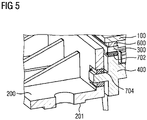
- FIG 5 Also in figure 5 are the plastic element 200 and the metal housing 400 compared to the representations in FIG figure 2 and 4 slightly modified.
- the metal housing 400 has only a short projection on its left edge shown in the figure, on the top and bottom of which adhesive 704 is arranged.
- the plastic element 200 and the metal housing 400 can be aligned with one another, and the required tolerance can thus be achieved without machining the metal.
Landscapes
- Engineering & Computer Science (AREA)
- Chemical & Material Sciences (AREA)
- Combustion & Propulsion (AREA)
- Transportation (AREA)
- Mechanical Engineering (AREA)
- Devices For Indicating Variable Information By Combining Individual Elements (AREA)
- Liquid Crystal (AREA)
Abstract
Description
- Die vorliegende Erfindung betrifft eine Anzeigevorrichtung aufweisend ein elektrooptisches Display und ein Metallgehäuse zum Einbau in ein Kraftfahrzeug, wobei die Anzeigevorrichtung zur Verbindung mit einem Kraftfahrzeug ausgestaltet ist. Bei einer Anzeigevorrichtung wird üblicher Weise ein Gehäuse in der der Art eines Druckgussbauteil (z.B. aus Magnesium oder Aluminium) als steifes tragendes Element eingesetzt. Die mit den Druckgussbauteilen erreichbaren Fertigungstoleranzen sind in der Regel zu groß. Die großen Fertigungstoleranzen führen zu unerwünschten Spaltmaßen zum Fahrzeug und können bei der Montage zu unerwünschten Krafteinleitungen führen. Die undefinierte Krafteinleitung führt dann zu unerwünschten Effekten in dem elektrooptischen Display.
- Um einen nahezu toleranzfreien Einbau einer vorgenannten Anzeigevorrichtung in ein Fahrzeug zu realisieren erfolgt dies üblicher Weise über Böllhof Elemente oder mittels geschraubten Elementen / Konsolen, die bei der Montage zu Referenzkanten / -flächen (z.B. zu einem Deckglas des elektrooptischen Displays) ausgerichtet werden. Diese Montageart ist aufwändig und teuer. Deshalb ist es weiterhin bekannt, die Druckgussbauteile spanend zu bearbeiten, um geforderte Toleranzen zu erreichen und so negative Auswirkungen auf das elektrooptische Display zu vermeiden. Auch diese spanende Bearbeitung ist aufwändig und teuer.
- Aufgabe der vorliegenden Erfindung ist es daher, eine Anzeigevorrichtung aufweisend ein elektrooptisches Display und ein Metallgehäuse zum Einbau in ein Kraftfahrzeug anzugeben, wobei die Anzeigevorrichtung zur Verbindung mit einem Kraftfahrzeug ausgestaltet ist und ein Verfahren zum Herstellen einer derartigen Anzeigevorrichtung anzugeben, die die einfacher und preiswerter zu realisieren sind, anzugeben.
- Diese Aufgabe wird durch eine Anzeigevorrichtung mit den Merkmalen des Patentanspruchs 1 und einem Verfahren mit den Merkmalen des Patentanspruchs 10 gelöst.
- Dadurch, dass das Metallgehäuse mit einem Kunststoffelement verbunden ist und das Kunststoffelement zur Verbindung mit dem Fahrzeug ausgestaltet ist, können die einfacher erreichbare hohe Toleranz des Kunststoffelements ausgenutzt und durch die Verklebung des Kunststoffelements mit dem Metallgehäuse größere Toleranzen des Metallgehäuses ausgeglichen werden.
- Wenn das Kunststoffelement eine Anbindung zur Verbindung der Anzeigevorrichtung mit einem Kraftfahrzeug aufweist, wird die Toleranz des Bauteils weiter verbessert. Hierbei kann die Anbindung rein aus Kunststoff hergestellt sein und möglicherweise durch eine Auflagefläche des Gehäuses zusätzlich unterstützt werden. Hierbei kann die Verklebung zwischen der Auflagefläche des Gehäuses und der Anbindung des Kunststoffelements alleine oder zusätzlich realisiert sein.
- Wenn das elektrooptische Display mit einem Kunststoffrahmen und der Kunststoffrahmen mit dem Metallgehäuse verklebt ist, ist das elektrooptische Display sicher und toleranzarm mit dem Metallgehäuse verbunden. Hierbei kann das elektrooptische Display direkt oder über ein Deckglas mit dem Kunststoffrahmen verbunden sein.
- Falls das elektrooptische Display mit dem Kunststoffrahmen direkt oder über ein Deckglas verclipst oder verschraubt ist und der Kunststoffrahmen mit dem Gehäuse verklebt ist, wird eine einfache Verbindung zwischen Metallgehäuse und elektrooptischen Display realisiert. Weiterhin ist das elektrooptische Display hierbei sicher und toleranzarm mit dem Metallgehäuse verbunden.
- Dadurch, dass das Kunststoffelement rahmenförmig ausgestaltet ist, wird eine besondere Stabilität des Kunststoffelements realisiert.
- Wenn die Anzeigevorrichtung eine Beleuchtungsvorrichtung aufweist, die zwischen dem elektrooptischen Display und dem Metallgehäuse angeordnet ist, kann ein durchleuchtbares elektrooptisches Display von seiner Rückseite durchleuchtet werden und ist dadurch auch in Dunkelheit gut sichtbar.
- Sofern die Beleuchtungsvorrichtung einen Lichtleiter aufweist können Lichtquellen der Beleuchtungsvorrichtung thermisch mit dem Gehäuse verbunden werden und Licht der Lichtquellen zu dem elektrooptischen Display geleitet werden.
- Falls die Anzeigevorrichtung eine Blende aufweist kann sie einfach optisch ansprechend gestaltet werden.
- Wenn die Blende zwischen dem elektrooptischen Display und dem Lichtleiter angeordnet ist kann störendes Streulicht unterdrückt werden und die Blende den Lichtleiter zusätzlich sichern.
- Dadurch, dass bei einem erfindungsgemäßen Verfahren zur Herstellung einer vorstehend beschriebenen Anzeigevorrichtung das Kunststoffelement zu dem Metallgehäuse so ausgerichtet wird, dass sich ein Zwischenraum zwischen dem Metallgehäuse und dem Kunststoffelement ergibt und der sich ergebender Zwischenraum zwischen dem Kunststoffelement und dem Gehäuse mit einem Klebstoff zumindest teilweise so ausgefüllt ist oder wird, dass das Gehäuse mit dem Kunststoffelement verklebt wird, kann auf einfache Weise die geforderte Toleranz erreicht werden. "Ausgefüllt ist" bedeutet hierbei, dass zunächst eines der beiden Bauteile mit Klebstoff beispielsweise raupenförmig versehen wird und dann die beiden Teile zueinander ausgerichtet werden. "Ausgefüllt wird" bedeutet, dass zunächst die beiden Bauteile zueinander ausgerichtet werden und dann der Klebstoff zugeführt wird. Die erreichbare Toleranz hängt hauptsächlich mit der erzielbaren Genauigkeit der Ausrichtung zwischen dem Metallgehäuse und dem Kunststoffelement ab.
- Diese Genauigkeit lässt sich insbesondere dadurch erreichen, dass das Metallgehäuse in eine erste Haltevorrichtung und das Kunststoffelement in eine zweite Haltevorrichtung eingespannt und danach zueinander ausgerichtet werden.
- Falls das elektrooptische Display mit dem Kunststoffrahmen verklebt wird, bevor das Kunststoffelement mit dem Metallgehäuse verklebt wird, werden auf das elektrooptische Display während und nach dem Zusammenbau keine unerwünschten Kräfte ausgeübt.
- Das elektrooptische Display kann auch als selbstleuchtendes Display, wie beispielsweise ein OLED, ausgestaltet sein.
- Die Erfindung wird nachfolgend an Hand der Figuren näher erläutert. Es zeigen:
-
Fig 1 eine Aufsicht auf ein Ausführungsbeispiel einer erfindungsgemäßen Anzeigevorrichtung -
Fig. 2 den Schnitt A-A ausFig.1 -
Fig 3 den Schnitt B-B ausFig 1 -
Fig. 4 eine erste Abwandlung der Darstellung ausFig. 2 -
Fig. 5 eine zweite Abwandlung der Darstellung ausFig. 2 - In
Figur 1 erkennt man von dem Ausführungsbeispiel der erfindungsgemäßen Anzeigevorrichtung ein Deckglas 100 des elektrooptischen Displays und ein Kunststoffelement 200. - In
Figur 2 erkennt man das Deckglas 100 eines ansonsten nicht dargestellten elektrooptischen Displays, ein Kunststoffelement 200 mit Anbindung 201, einen Kunststoffrahmen 300, ein Metallgehäuse 400, ein Klebeband 600 und Klebstoff 701, 702. Das Kunststoffelement 200 ist mittels des Klebstoffs 701 mit dem Metallgehäuse 400 verbunden und weist die Anbindung 201 auf. Diese Anbindung 201 ist vorgesehen und ausgebildet, in einem nicht dargestellten Fahrzeug auf entsprechenden Auflageflächen aufgelegt zu werden und mittels eines Befestigungselements wie beispielsweise einer Schraube oder eines Niets fixiert zu werden. Dieses Befestigungselement kann beispielsweise durch das im Schnitt dargestellte Loch geführt werden. Das Deckglas 100 des ansonsten nicht dargestellten elektrooptischen Displays ist über das Klebeband 600 mit dem Kunststoffrahmen 300 verbunden, der über den Klebstoff 702 mit dem Metallgehäuse 400 verbunden ist. Durch die Ausrichtung des Kunststoffelements 200 zu dem Metallgehäuse 400 wird auf einfache Art und Weise die geforderte enge Toleranz ohne eine spanende Metallbearbeitung des Metallgehäuses 400 erreicht. Eine weitere Verbesserung der Toleranz wird durch den Klebstoff 702 erreicht, wenn der Kunststoffrahmen 300 zu dem Metallgehäuse 400 ausgerichtet wird. Das Kunststoffelement kann beispielsweise drei oder vier Anbindungen 201 aufweisen. - In
Figur 3 erkennt man neben den bereits beschriebenen Bauteilen eine Verklebung 102, ein elektrooptisches Display 101, einen Lichtleiter 800, eine Reflektor-Folie 801, eine Streufolie 802 und einen Zwischenraum 900. Das elektrooptische Display 101 ist über die Verklebung 102 mit dem Deckglas 100 verbunden. Die Verklebung 102 kann beispielsweise aus einem transparenten doppelseitig beschichteten Klebeband oder einem sonstigen Optical-Bonding Material bestehen. Der Kunststoffrahmen 300 wirkt einerseits als Blende und fixiert den Lichtleiter 800 samt Reflektorfolie 801 und Streufolie 802. - In
Figur 4 sind das Kunststoffelement 200 und das Metallgehäuse 400 gegenüber der Darstellung inFigur 2 leicht abgeändert. Das Kunststoffelement 200 wird im Bereich der Anbindung 201 nicht mehr von dem Metallgehäuse 400 unterstützt. Es ist vielmehr wie dargestellt nur an seinem Rand über Klebstoff 703 mit dem Metallgehäuse 400 verbunden. Hierbei kann der sich zwischen dem Kunststoffelement 200 und dem Gehäuse 400 ergebende Zwischenraum vollständig mit Klebstoff 703 ausgefüllt sein oder wie dargestellt an den in der Figur dargestellten jeweils horizontalen Flächen. - Auch in
Figur 5 sind das Kunststoffelement 200 und das Metallgehäuse 400 gegenüber den Darstellungen inFigur 2 und4 leicht abgeändert. Hier weist das Metallgehäuse 400 an seinem in der Figur dargestellten linken Rand nur einen kurzen Vorsprung auf, an dessen Oberseite und Unterseite jeweils Klebstoff 704 angeordnet ist. Hierdurch können bei der Montage der Anzeigevorrichtung vor Abbinden des Klebstoffs 704 das Kunststoffelement 200 und das Metallgehäuse 400 zueinander ausgerichtet werden und so die geforderte Toleranz ohne eine Metallbearbeitung erreicht werden. -
- 100
- Deckglas des elektrooptischen Displays 101
- 101
- elektrooptisches Display
- 102
- Verklebung
- 200
- Kunststoffelement
- 201
- Anbindung
- 300
- Kunststoffrahmen
- 400
- Metallgehäuse
- 600
- Klebeband
- 701, 703, 704
- Klebstoff zwischen Metallgehäuse und Kunststoffelement
- 702
- Klebstoff zwischen Metallgehäuse Kunststoffrahmen
- 800
- Lichtleiter
- 801
- Reflektor-Folie
- 802
- Streufolie
- 900
- Zwischenraum
Claims (12)
- Anzeigevorrichtung aufweisend ein elektrooptisches Display (101) und ein Metallgehäuse (400) zum Einbau in ein Kraftfahrzeug, wobei die Anzeigevorrichtung zur Verbindung mit dem Kraftfahrzeug ausgestaltet ist, dadurch gekennzeichnet, dass das Metallgehäuse (400) mit einem Kunststoffelement (200) verbunden ist, dass das Kunststoffelement (200) zur Verbindung mit dem Kraftfahrzeug ausgestaltet ist, dass das Kunststoffelement (200) mit dem Metallgehäuse (400) mittels Klebstoff (701, 703, 704) verklebt ist.
- Anzeigevorrichtung nach Patentanspruch 1, dadurch gekennzeichnet, dass das Kunststoffelement (200) eine Anbindung (201) zur Verbindung der Anzeigevorrichtung mit dem Kraftfahrzeug aufweist.
- Anzeigevorrichtung nach Patentanspruch 1 oder 2, dadurch gekennzeichnet, dass das elektrooptische Display (101) über einen Kunststoffrahmen (300) mit dem Metallgehäuse (400) mittels Klebstoff (702) verklebt ist.
- Anzeigevorrichtung nach Patentanspruch 1 oder 2, dadurch gekennzeichnet, dass das elektrooptische Display (101) mit einem Kunststoffrahmen verclipst oder verschraubt ist und der Kunststoffrahmen mit dem Gehäuse (400) mittels Klebstoff (702) verklebt ist.
- Anzeigevorrichtung nach einem der vorstehenden Patentansprüche, dadurch gekennzeichnet, dass das Kunststoffelement (200) rahmenförmig ausgestaltet ist.
- Anzeigevorrichtung nach einem der vorstehenden Patentansprüche, dadurch gekennzeichnet, dass sie eine Beleuchtungsvorrichtung (800, 801, 802) aufweist, die zwischen dem elektrooptischen Display (101) und dem Metallgehäuse (400) angeordnet ist.
- Anzeigevorrichtung nach Patentanspruch 6, dadurch gekennzeichnet, dass die Beleuchtungsvorrichtung (800, 801, 802) einen Lichtleiter (800) aufweist.
- Anzeigevorrichtung nach einem der Patentansprüche 6 oder 7, dadurch gekennzeichnet, dass sie eine Blende (300) aufweist.
- Anzeigevorrichtung nach Patentanspruch 7 und 8, dadurch gekennzeichnet, dass die Blende (300) als Kunststoffrahmen (300) ausgebildet und zwischen dem elektrooptischen Display (101) und dem Lichtleiter (800) angeordnet ist.
- Verfahren zur Herstellung einer Anzeigevorrichtung nach einem oder mehreren der vorstehenden Patentansprüche, dadurch gekennzeichnet, dass das Kunststoffelement (200) zu dem Metallgehäuse (400) so ausgerichtet wird, dass sich ein Zwischenraum zwischen dem Metallgehäuse (400) und dem Kunststoffelement (200) ergibt und der sich ergebender Zwischenraum zwischen dem Kunststoffelement (200) und dem Metallgehäuse (400) mit einem Klebstoff (701, 703, 704) zumindest teilweise so ausgefüllt ist oder wird, dass das Gehäuse (400) mit dem Kunststoffelement (200) verklebt wird.
- Verfahren nach Patentanspruch 10, dadurch gekennzeichnet, dass das Metallgehäuse (400) in eine erste Haltevorrichtung und das Kunststoffelement (200) in eine zweite Haltevorrichtung eingespannt und zueinander ausgerichtet werden.
- Verfahren nach Patentanspruch 10 oder 11, dadurch gekennzeichnet, dass das elektrooptische Display (101) mit dem Kunststoffrahmen (300) verklebt wird, bevor das Kunststoffelement (200) mit dem Metallgehäuse (400) verklebt wird.
Priority Applications (1)
| Application Number | Priority Date | Filing Date | Title |
|---|---|---|---|
| RS20230425A RS64245B1 (sr) | 2020-10-14 | 2021-10-11 | Indikatorski uređaj i postupak za njegovu proizvodnju |
Applications Claiming Priority (1)
| Application Number | Priority Date | Filing Date | Title |
|---|---|---|---|
| DE102020212990.8A DE102020212990A1 (de) | 2020-10-14 | 2020-10-14 | Anzeigevorrichtung |
Publications (2)
| Publication Number | Publication Date |
|---|---|
| EP3984802A1 true EP3984802A1 (de) | 2022-04-20 |
| EP3984802B1 EP3984802B1 (de) | 2023-05-24 |
Family
ID=78087201
Family Applications (1)
| Application Number | Title | Priority Date | Filing Date |
|---|---|---|---|
| EP21201969.9A Active EP3984802B1 (de) | 2020-10-14 | 2021-10-11 | Anzeigevorrichtung und verfahren zur herstellung eines solchen |
Country Status (3)
| Country | Link |
|---|---|
| EP (1) | EP3984802B1 (de) |
| DE (1) | DE102020212990A1 (de) |
| RS (1) | RS64245B1 (de) |
Citations (3)
| Publication number | Priority date | Publication date | Assignee | Title |
|---|---|---|---|---|
| US20140240638A1 (en) * | 2012-08-10 | 2014-08-28 | Komatsu Ltd. | Monitor and Working Vehicle Provided with the Monitor |
| US20190212605A1 (en) * | 2018-01-10 | 2019-07-11 | Alpine Electronics, Inc. | On-vehicle display device |
| WO2020081488A1 (en) * | 2018-10-18 | 2020-04-23 | Corning Incorporated | Frame for auto interior display panel |
Family Cites Families (4)
| Publication number | Priority date | Publication date | Assignee | Title |
|---|---|---|---|---|
| US7044546B2 (en) | 2002-08-14 | 2006-05-16 | Johnson Safety, Inc. | Headrest-mounted monitor |
| DE102011082933A1 (de) | 2011-09-19 | 2013-03-21 | Robert Bosch Gmbh | Anzeigevorrichtung und Verfahren zur Herstellung einer Anzeigevorrichtung für ein Informationssystem für ein Fahrzeug |
| DE102014019324B4 (de) | 2014-12-20 | 2025-08-14 | Continental Automotive Technologies GmbH | Displayrahmen für ein Display eines Kraftfahrzeugs |
| WO2020239851A1 (de) | 2019-05-28 | 2020-12-03 | Behr-Hella Thermocontrol Gmbh | Anzeigevorrichtung für ein fahrzeug |
-
2020
- 2020-10-14 DE DE102020212990.8A patent/DE102020212990A1/de not_active Withdrawn
-
2021
- 2021-10-11 RS RS20230425A patent/RS64245B1/sr unknown
- 2021-10-11 EP EP21201969.9A patent/EP3984802B1/de active Active
Patent Citations (3)
| Publication number | Priority date | Publication date | Assignee | Title |
|---|---|---|---|---|
| US20140240638A1 (en) * | 2012-08-10 | 2014-08-28 | Komatsu Ltd. | Monitor and Working Vehicle Provided with the Monitor |
| US20190212605A1 (en) * | 2018-01-10 | 2019-07-11 | Alpine Electronics, Inc. | On-vehicle display device |
| WO2020081488A1 (en) * | 2018-10-18 | 2020-04-23 | Corning Incorporated | Frame for auto interior display panel |
Also Published As
| Publication number | Publication date |
|---|---|
| RS64245B1 (sr) | 2023-06-30 |
| DE102020212990A1 (de) | 2022-04-14 |
| EP3984802B1 (de) | 2023-05-24 |
Similar Documents
| Publication | Publication Date | Title |
|---|---|---|
| EP2550556B1 (de) | Display-anordnung und deren montage | |
| DE102018122330B4 (de) | Antriebsvorrichtung | |
| EP3828035A1 (de) | Beleuchtungseinrichtung, insbesondere eine konturbeleuchtung für ein kraftfahrzeug | |
| EP2639107B1 (de) | Beleuchtungseinrichtung, insbesondere Konturbeleuchtung für ein Kraftfahrzeug | |
| EP2811219A1 (de) | Beleuchtungskörper für ein Fahrzeug | |
| DE202015100321U1 (de) | Formteil, insbesondere als Formteil ausgebildetes Dekorteil und/oder Verkleidungsteil für einen Fahrzeuginnenraum | |
| DE60310805T2 (de) | Stilistisches Element und Kraftfahrzeug mit einem solchen stilistischen Element | |
| DE4019007A1 (de) | Armaturenbrett fuer kraftfahrzeuge | |
| EP3984802B1 (de) | Anzeigevorrichtung und verfahren zur herstellung eines solchen | |
| DE102022108786B4 (de) | Fahrzeugscheibe mit Beleuchtungseinrichtung und Koppelelement | |
| DE102016123203A1 (de) | Beleuchtungsvorrichtung für Fahrzeuge | |
| DE102016207964A1 (de) | Außenspiegel für ein Kraftfahrzeug | |
| DE202018101097U1 (de) | Dachreling | |
| DE102020115409A1 (de) | Beleuchtungsvorrichtung für ein Kraftfahrzeug mit einem Panoramadach | |
| EP3138735A1 (de) | Aussenspiegel für ein kraftfahrzeug | |
| DE102010025247A1 (de) | Anzeigeeinrichtung | |
| DE102022131483A1 (de) | Holografische Beleuchtungsvorrichtung für Fahrzeuge | |
| DE102012009135A1 (de) | Optisches System | |
| DE202014105892U1 (de) | Bauteil, insbesondere Innenausstattungsteil für Fahrzeuge mit integrierter Beleuchtung | |
| EP2550182B1 (de) | Fahrzeugaussenspiegelpaar | |
| DE102023211022B3 (de) | Beleuchtungsvorrichtung, Verfahren zur Herstellung einer solchen Beleuchtungsvorrichtung sowie Fahrzeug mit einer Beleuchtungsvorrichtung | |
| DE19933714B4 (de) | Leuchte mit zweiter Lichtquelle | |
| DE102021124889A1 (de) | Lichtmodul mit einer Befestigungseinrichtung | |
| DE102025122060A1 (de) | Zierelementanordnung | |
| DE10012760B4 (de) | Verfahren zur Montage des Scheinwerfers eines Kraftfahrzeuges |
Legal Events
| Date | Code | Title | Description |
|---|---|---|---|
| PUAI | Public reference made under article 153(3) epc to a published international application that has entered the european phase |
Free format text: ORIGINAL CODE: 0009012 |
|
| STAA | Information on the status of an ep patent application or granted ep patent |
Free format text: STATUS: THE APPLICATION HAS BEEN PUBLISHED |
|
| AK | Designated contracting states |
Kind code of ref document: A1 Designated state(s): AL AT BE BG CH CY CZ DE DK EE ES FI FR GB GR HR HU IE IS IT LI LT LU LV MC MK MT NL NO PL PT RO RS SE SI SK SM TR |
|
| RAP1 | Party data changed (applicant data changed or rights of an application transferred) |
Owner name: CONTINENTAL AUTOMOTIVE TECHNOLOGIES GMBH |
|
| STAA | Information on the status of an ep patent application or granted ep patent |
Free format text: STATUS: REQUEST FOR EXAMINATION WAS MADE |
|
| 17P | Request for examination filed |
Effective date: 20221020 |
|
| RBV | Designated contracting states (corrected) |
Designated state(s): AL AT BE BG CH CY CZ DE DK EE ES FI FR GB GR HR HU IE IS IT LI LT LU LV MC MK MT NL NO PL PT RO RS SE SI SK SM TR |
|
| GRAP | Despatch of communication of intention to grant a patent |
Free format text: ORIGINAL CODE: EPIDOSNIGR1 |
|
| STAA | Information on the status of an ep patent application or granted ep patent |
Free format text: STATUS: GRANT OF PATENT IS INTENDED |
|
| INTG | Intention to grant announced |
Effective date: 20230201 |
|
| GRAS | Grant fee paid |
Free format text: ORIGINAL CODE: EPIDOSNIGR3 |
|
| GRAA | (expected) grant |
Free format text: ORIGINAL CODE: 0009210 |
|
| STAA | Information on the status of an ep patent application or granted ep patent |
Free format text: STATUS: THE PATENT HAS BEEN GRANTED |
|
| AK | Designated contracting states |
Kind code of ref document: B1 Designated state(s): AL AT BE BG CH CY CZ DE DK EE ES FI FR GB GR HR HU IE IS IT LI LT LU LV MC MK MT NL NO PL PT RO RS SE SI SK SM TR |
|
| REG | Reference to a national code |
Ref country code: GB Ref legal event code: FG4D Free format text: NOT ENGLISH |
|
| REG | Reference to a national code |
Ref country code: CH Ref legal event code: EP |
|
| REG | Reference to a national code |
Ref country code: DE Ref legal event code: R096 Ref document number: 502021000702 Country of ref document: DE |
|
| REG | Reference to a national code |
Ref country code: AT Ref legal event code: REF Ref document number: 1569310 Country of ref document: AT Kind code of ref document: T Effective date: 20230615 |
|
| REG | Reference to a national code |
Ref country code: IE Ref legal event code: FG4D Free format text: LANGUAGE OF EP DOCUMENT: GERMAN |
|
| REG | Reference to a national code |
Ref country code: LT Ref legal event code: MG9D |
|
| REG | Reference to a national code |
Ref country code: NL Ref legal event code: MP Effective date: 20230524 |
|
| PG25 | Lapsed in a contracting state [announced via postgrant information from national office to epo] |
Ref country code: SE Free format text: LAPSE BECAUSE OF FAILURE TO SUBMIT A TRANSLATION OF THE DESCRIPTION OR TO PAY THE FEE WITHIN THE PRESCRIBED TIME-LIMIT Effective date: 20230524 Ref country code: PT Free format text: LAPSE BECAUSE OF FAILURE TO SUBMIT A TRANSLATION OF THE DESCRIPTION OR TO PAY THE FEE WITHIN THE PRESCRIBED TIME-LIMIT Effective date: 20230925 Ref country code: NO Free format text: LAPSE BECAUSE OF FAILURE TO SUBMIT A TRANSLATION OF THE DESCRIPTION OR TO PAY THE FEE WITHIN THE PRESCRIBED TIME-LIMIT Effective date: 20230824 Ref country code: NL Free format text: LAPSE BECAUSE OF FAILURE TO SUBMIT A TRANSLATION OF THE DESCRIPTION OR TO PAY THE FEE WITHIN THE PRESCRIBED TIME-LIMIT Effective date: 20230524 Ref country code: ES Free format text: LAPSE BECAUSE OF FAILURE TO SUBMIT A TRANSLATION OF THE DESCRIPTION OR TO PAY THE FEE WITHIN THE PRESCRIBED TIME-LIMIT Effective date: 20230524 |
|
| PG25 | Lapsed in a contracting state [announced via postgrant information from national office to epo] |
Ref country code: PL Free format text: LAPSE BECAUSE OF FAILURE TO SUBMIT A TRANSLATION OF THE DESCRIPTION OR TO PAY THE FEE WITHIN THE PRESCRIBED TIME-LIMIT Effective date: 20230524 Ref country code: LV Free format text: LAPSE BECAUSE OF FAILURE TO SUBMIT A TRANSLATION OF THE DESCRIPTION OR TO PAY THE FEE WITHIN THE PRESCRIBED TIME-LIMIT Effective date: 20230524 Ref country code: LT Free format text: LAPSE BECAUSE OF FAILURE TO SUBMIT A TRANSLATION OF THE DESCRIPTION OR TO PAY THE FEE WITHIN THE PRESCRIBED TIME-LIMIT Effective date: 20230524 Ref country code: IS Free format text: LAPSE BECAUSE OF FAILURE TO SUBMIT A TRANSLATION OF THE DESCRIPTION OR TO PAY THE FEE WITHIN THE PRESCRIBED TIME-LIMIT Effective date: 20230924 Ref country code: HR Free format text: LAPSE BECAUSE OF FAILURE TO SUBMIT A TRANSLATION OF THE DESCRIPTION OR TO PAY THE FEE WITHIN THE PRESCRIBED TIME-LIMIT Effective date: 20230524 Ref country code: GR Free format text: LAPSE BECAUSE OF FAILURE TO SUBMIT A TRANSLATION OF THE DESCRIPTION OR TO PAY THE FEE WITHIN THE PRESCRIBED TIME-LIMIT Effective date: 20230825 |
|
| PG25 | Lapsed in a contracting state [announced via postgrant information from national office to epo] |
Ref country code: FI Free format text: LAPSE BECAUSE OF FAILURE TO SUBMIT A TRANSLATION OF THE DESCRIPTION OR TO PAY THE FEE WITHIN THE PRESCRIBED TIME-LIMIT Effective date: 20230524 |
|
| PG25 | Lapsed in a contracting state [announced via postgrant information from national office to epo] |
Ref country code: SK Free format text: LAPSE BECAUSE OF FAILURE TO SUBMIT A TRANSLATION OF THE DESCRIPTION OR TO PAY THE FEE WITHIN THE PRESCRIBED TIME-LIMIT Effective date: 20230524 |
|
| PG25 | Lapsed in a contracting state [announced via postgrant information from national office to epo] |
Ref country code: SM Free format text: LAPSE BECAUSE OF FAILURE TO SUBMIT A TRANSLATION OF THE DESCRIPTION OR TO PAY THE FEE WITHIN THE PRESCRIBED TIME-LIMIT Effective date: 20230524 Ref country code: SK Free format text: LAPSE BECAUSE OF FAILURE TO SUBMIT A TRANSLATION OF THE DESCRIPTION OR TO PAY THE FEE WITHIN THE PRESCRIBED TIME-LIMIT Effective date: 20230524 Ref country code: RO Free format text: LAPSE BECAUSE OF FAILURE TO SUBMIT A TRANSLATION OF THE DESCRIPTION OR TO PAY THE FEE WITHIN THE PRESCRIBED TIME-LIMIT Effective date: 20230524 Ref country code: EE Free format text: LAPSE BECAUSE OF FAILURE TO SUBMIT A TRANSLATION OF THE DESCRIPTION OR TO PAY THE FEE WITHIN THE PRESCRIBED TIME-LIMIT Effective date: 20230524 Ref country code: DK Free format text: LAPSE BECAUSE OF FAILURE TO SUBMIT A TRANSLATION OF THE DESCRIPTION OR TO PAY THE FEE WITHIN THE PRESCRIBED TIME-LIMIT Effective date: 20230524 Ref country code: CZ Free format text: LAPSE BECAUSE OF FAILURE TO SUBMIT A TRANSLATION OF THE DESCRIPTION OR TO PAY THE FEE WITHIN THE PRESCRIBED TIME-LIMIT Effective date: 20230524 |
|
| REG | Reference to a national code |
Ref country code: DE Ref legal event code: R081 Ref document number: 502021000702 Country of ref document: DE Owner name: CONTINENTAL AUTOMOTIVE TECHNOLOGIES GMBH, DE Free format text: FORMER OWNER: CONTINENTAL AUTOMOTIVE TECHNOLOGIES GMBH, 30165 HANNOVER, DE Ref country code: DE Ref legal event code: R081 Ref document number: 502021000702 Country of ref document: DE Owner name: AUMOVIO GERMANY GMBH, DE Free format text: FORMER OWNER: CONTINENTAL AUTOMOTIVE TECHNOLOGIES GMBH, 30165 HANNOVER, DE |
|
| REG | Reference to a national code |
Ref country code: DE Ref legal event code: R097 Ref document number: 502021000702 Country of ref document: DE |
|
| PLBE | No opposition filed within time limit |
Free format text: ORIGINAL CODE: 0009261 |
|
| STAA | Information on the status of an ep patent application or granted ep patent |
Free format text: STATUS: NO OPPOSITION FILED WITHIN TIME LIMIT |
|
| 26N | No opposition filed |
Effective date: 20240227 |
|
| PG25 | Lapsed in a contracting state [announced via postgrant information from national office to epo] |
Ref country code: SI Free format text: LAPSE BECAUSE OF FAILURE TO SUBMIT A TRANSLATION OF THE DESCRIPTION OR TO PAY THE FEE WITHIN THE PRESCRIBED TIME-LIMIT Effective date: 20230524 |
|
| PG25 | Lapsed in a contracting state [announced via postgrant information from national office to epo] |
Ref country code: SI Free format text: LAPSE BECAUSE OF FAILURE TO SUBMIT A TRANSLATION OF THE DESCRIPTION OR TO PAY THE FEE WITHIN THE PRESCRIBED TIME-LIMIT Effective date: 20230524 Ref country code: IT Free format text: LAPSE BECAUSE OF FAILURE TO SUBMIT A TRANSLATION OF THE DESCRIPTION OR TO PAY THE FEE WITHIN THE PRESCRIBED TIME-LIMIT Effective date: 20230524 Ref country code: MC Free format text: LAPSE BECAUSE OF FAILURE TO SUBMIT A TRANSLATION OF THE DESCRIPTION OR TO PAY THE FEE WITHIN THE PRESCRIBED TIME-LIMIT Effective date: 20230524 |
|
| REG | Reference to a national code |
Ref country code: BE Ref legal event code: MM Effective date: 20231031 |
|
| PG25 | Lapsed in a contracting state [announced via postgrant information from national office to epo] |
Ref country code: LU Free format text: LAPSE BECAUSE OF NON-PAYMENT OF DUE FEES Effective date: 20231011 |
|
| PG25 | Lapsed in a contracting state [announced via postgrant information from national office to epo] |
Ref country code: LU Free format text: LAPSE BECAUSE OF NON-PAYMENT OF DUE FEES Effective date: 20231011 |
|
| PG25 | Lapsed in a contracting state [announced via postgrant information from national office to epo] |
Ref country code: BE Free format text: LAPSE BECAUSE OF NON-PAYMENT OF DUE FEES Effective date: 20231031 |
|
| PG25 | Lapsed in a contracting state [announced via postgrant information from national office to epo] |
Ref country code: IE Free format text: LAPSE BECAUSE OF NON-PAYMENT OF DUE FEES Effective date: 20231011 |
|
| PG25 | Lapsed in a contracting state [announced via postgrant information from national office to epo] |
Ref country code: IE Free format text: LAPSE BECAUSE OF NON-PAYMENT OF DUE FEES Effective date: 20231011 |
|
| PG25 | Lapsed in a contracting state [announced via postgrant information from national office to epo] |
Ref country code: BG Free format text: LAPSE BECAUSE OF FAILURE TO SUBMIT A TRANSLATION OF THE DESCRIPTION OR TO PAY THE FEE WITHIN THE PRESCRIBED TIME-LIMIT Effective date: 20230524 |
|
| PG25 | Lapsed in a contracting state [announced via postgrant information from national office to epo] |
Ref country code: BG Free format text: LAPSE BECAUSE OF FAILURE TO SUBMIT A TRANSLATION OF THE DESCRIPTION OR TO PAY THE FEE WITHIN THE PRESCRIBED TIME-LIMIT Effective date: 20230524 |
|
| REG | Reference to a national code |
Ref country code: CH Ref legal event code: PL |
|
| PG25 | Lapsed in a contracting state [announced via postgrant information from national office to epo] |
Ref country code: CH Free format text: LAPSE BECAUSE OF NON-PAYMENT OF DUE FEES Effective date: 20241031 |
|
| PG25 | Lapsed in a contracting state [announced via postgrant information from national office to epo] |
Ref country code: CY Free format text: LAPSE BECAUSE OF FAILURE TO SUBMIT A TRANSLATION OF THE DESCRIPTION OR TO PAY THE FEE WITHIN THE PRESCRIBED TIME-LIMIT; INVALID AB INITIO Effective date: 20211011 |
|
| PGFP | Annual fee paid to national office [announced via postgrant information from national office to epo] |
Ref country code: RS Payment date: 20250922 Year of fee payment: 5 |
|
| PG25 | Lapsed in a contracting state [announced via postgrant information from national office to epo] |
Ref country code: TR Free format text: LAPSE BECAUSE OF FAILURE TO SUBMIT A TRANSLATION OF THE DESCRIPTION OR TO PAY THE FEE WITHIN THE PRESCRIBED TIME-LIMIT Effective date: 20230524 |
|
| PGFP | Annual fee paid to national office [announced via postgrant information from national office to epo] |
Ref country code: DE Payment date: 20251031 Year of fee payment: 5 |
|
| PGFP | Annual fee paid to national office [announced via postgrant information from national office to epo] |
Ref country code: GB Payment date: 20251021 Year of fee payment: 5 |
|
| PGFP | Annual fee paid to national office [announced via postgrant information from national office to epo] |
Ref country code: AT Payment date: 20260113 Year of fee payment: 5 |
|
| PGFP | Annual fee paid to national office [announced via postgrant information from national office to epo] |
Ref country code: FR Payment date: 20251027 Year of fee payment: 5 |
|
| REG | Reference to a national code |
Ref country code: DE Ref legal event code: R081 Ref document number: 502021000702 Country of ref document: DE Owner name: AUMOVIO GERMANY GMBH, DE Free format text: FORMER OWNER: CONTINENTAL AUTOMOTIVE TECHNOLOGIES GMBH, 30175 HANNOVER, DE |
|
| PG25 | Lapsed in a contracting state [announced via postgrant information from national office to epo] |
Ref country code: HU Free format text: LAPSE BECAUSE OF FAILURE TO SUBMIT A TRANSLATION OF THE DESCRIPTION OR TO PAY THE FEE WITHIN THE PRESCRIBED TIME-LIMIT; INVALID AB INITIO Effective date: 20211011 |