EP3984719A1 - Verfahren zum herstellen eines gebläserads - Google Patents
Verfahren zum herstellen eines gebläserads Download PDFInfo
- Publication number
- EP3984719A1 EP3984719A1 EP21196052.1A EP21196052A EP3984719A1 EP 3984719 A1 EP3984719 A1 EP 3984719A1 EP 21196052 A EP21196052 A EP 21196052A EP 3984719 A1 EP3984719 A1 EP 3984719A1
- Authority
- EP
- European Patent Office
- Prior art keywords
- nozzles
- shut
- impeller
- impeller blades
- plastic
- Prior art date
- Legal status (The legal status is an assumption and is not a legal conclusion. Google has not performed a legal analysis and makes no representation as to the accuracy of the status listed.)
- Granted
Links
Images

Classifications
-
- B—PERFORMING OPERATIONS; TRANSPORTING
- B29—WORKING OF PLASTICS; WORKING OF SUBSTANCES IN A PLASTIC STATE IN GENERAL
- B29C—SHAPING OR JOINING OF PLASTICS; SHAPING OF MATERIAL IN A PLASTIC STATE, NOT OTHERWISE PROVIDED FOR; AFTER-TREATMENT OF THE SHAPED PRODUCTS, e.g. REPAIRING
- B29C45/00—Injection moulding, i.e. forcing the required volume of moulding material through a nozzle into a closed mould; Apparatus therefor
- B29C45/17—Component parts, details or accessories; Auxiliary operations
- B29C45/20—Injection nozzles
- B29C45/22—Multiple nozzle systems
-
- B—PERFORMING OPERATIONS; TRANSPORTING
- B29—WORKING OF PLASTICS; WORKING OF SUBSTANCES IN A PLASTIC STATE IN GENERAL
- B29C—SHAPING OR JOINING OF PLASTICS; SHAPING OF MATERIAL IN A PLASTIC STATE, NOT OTHERWISE PROVIDED FOR; AFTER-TREATMENT OF THE SHAPED PRODUCTS, e.g. REPAIRING
- B29C45/00—Injection moulding, i.e. forcing the required volume of moulding material through a nozzle into a closed mould; Apparatus therefor
- B29C45/17—Component parts, details or accessories; Auxiliary operations
- B29C45/26—Moulds
- B29C45/27—Sprue channels ; Runner channels or runner nozzles
-
- B—PERFORMING OPERATIONS; TRANSPORTING
- B29—WORKING OF PLASTICS; WORKING OF SUBSTANCES IN A PLASTIC STATE IN GENERAL
- B29C—SHAPING OR JOINING OF PLASTICS; SHAPING OF MATERIAL IN A PLASTIC STATE, NOT OTHERWISE PROVIDED FOR; AFTER-TREATMENT OF THE SHAPED PRODUCTS, e.g. REPAIRING
- B29C45/00—Injection moulding, i.e. forcing the required volume of moulding material through a nozzle into a closed mould; Apparatus therefor
- B29C45/0005—Injection moulding, i.e. forcing the required volume of moulding material through a nozzle into a closed mould; Apparatus therefor using fibre reinforcements
-
- B—PERFORMING OPERATIONS; TRANSPORTING
- B29—WORKING OF PLASTICS; WORKING OF SUBSTANCES IN A PLASTIC STATE IN GENERAL
- B29C—SHAPING OR JOINING OF PLASTICS; SHAPING OF MATERIAL IN A PLASTIC STATE, NOT OTHERWISE PROVIDED FOR; AFTER-TREATMENT OF THE SHAPED PRODUCTS, e.g. REPAIRING
- B29C45/00—Injection moulding, i.e. forcing the required volume of moulding material through a nozzle into a closed mould; Apparatus therefor
- B29C45/0025—Preventing defects on the moulded article, e.g. weld lines, shrinkage marks
-
- B—PERFORMING OPERATIONS; TRANSPORTING
- B29—WORKING OF PLASTICS; WORKING OF SUBSTANCES IN A PLASTIC STATE IN GENERAL
- B29C—SHAPING OR JOINING OF PLASTICS; SHAPING OF MATERIAL IN A PLASTIC STATE, NOT OTHERWISE PROVIDED FOR; AFTER-TREATMENT OF THE SHAPED PRODUCTS, e.g. REPAIRING
- B29C45/00—Injection moulding, i.e. forcing the required volume of moulding material through a nozzle into a closed mould; Apparatus therefor
- B29C45/17—Component parts, details or accessories; Auxiliary operations
- B29C45/20—Injection nozzles
- B29C45/23—Feed stopping equipment
-
- B—PERFORMING OPERATIONS; TRANSPORTING
- B29—WORKING OF PLASTICS; WORKING OF SUBSTANCES IN A PLASTIC STATE IN GENERAL
- B29C—SHAPING OR JOINING OF PLASTICS; SHAPING OF MATERIAL IN A PLASTIC STATE, NOT OTHERWISE PROVIDED FOR; AFTER-TREATMENT OF THE SHAPED PRODUCTS, e.g. REPAIRING
- B29C45/00—Injection moulding, i.e. forcing the required volume of moulding material through a nozzle into a closed mould; Apparatus therefor
- B29C45/17—Component parts, details or accessories; Auxiliary operations
- B29C45/20—Injection nozzles
- B29C45/23—Feed stopping equipment
- B29C45/231—Needle valve systems therefor
-
- F—MECHANICAL ENGINEERING; LIGHTING; HEATING; WEAPONS; BLASTING
- F04—POSITIVE - DISPLACEMENT MACHINES FOR LIQUIDS; PUMPS FOR LIQUIDS OR ELASTIC FLUIDS
- F04D—NON-POSITIVE-DISPLACEMENT PUMPS
- F04D29/00—Details, component parts, or accessories
- F04D29/02—Selection of particular materials
- F04D29/023—Selection of particular materials especially adapted for elastic fluid pumps
-
- F—MECHANICAL ENGINEERING; LIGHTING; HEATING; WEAPONS; BLASTING
- F04—POSITIVE - DISPLACEMENT MACHINES FOR LIQUIDS; PUMPS FOR LIQUIDS OR ELASTIC FLUIDS
- F04D—NON-POSITIVE-DISPLACEMENT PUMPS
- F04D29/00—Details, component parts, or accessories
- F04D29/26—Rotors specially for elastic fluids
- F04D29/28—Rotors specially for elastic fluids for centrifugal or helico-centrifugal pumps for radial-flow or helico-centrifugal pumps
- F04D29/281—Rotors specially for elastic fluids for centrifugal or helico-centrifugal pumps for radial-flow or helico-centrifugal pumps for fans or blowers
- F04D29/282—Rotors specially for elastic fluids for centrifugal or helico-centrifugal pumps for radial-flow or helico-centrifugal pumps for fans or blowers the leading edge of each vane being substantially parallel to the rotation axis
-
- F—MECHANICAL ENGINEERING; LIGHTING; HEATING; WEAPONS; BLASTING
- F04—POSITIVE - DISPLACEMENT MACHINES FOR LIQUIDS; PUMPS FOR LIQUIDS OR ELASTIC FLUIDS
- F04D—NON-POSITIVE-DISPLACEMENT PUMPS
- F04D29/00—Details, component parts, or accessories
- F04D29/26—Rotors specially for elastic fluids
- F04D29/28—Rotors specially for elastic fluids for centrifugal or helico-centrifugal pumps for radial-flow or helico-centrifugal pumps
- F04D29/30—Vanes
-
- B—PERFORMING OPERATIONS; TRANSPORTING
- B29—WORKING OF PLASTICS; WORKING OF SUBSTANCES IN A PLASTIC STATE IN GENERAL
- B29C—SHAPING OR JOINING OF PLASTICS; SHAPING OF MATERIAL IN A PLASTIC STATE, NOT OTHERWISE PROVIDED FOR; AFTER-TREATMENT OF THE SHAPED PRODUCTS, e.g. REPAIRING
- B29C45/00—Injection moulding, i.e. forcing the required volume of moulding material through a nozzle into a closed mould; Apparatus therefor
- B29C45/0025—Preventing defects on the moulded article, e.g. weld lines, shrinkage marks
- B29C2045/0027—Gate or gate mark locations
-
- B—PERFORMING OPERATIONS; TRANSPORTING
- B29—WORKING OF PLASTICS; WORKING OF SUBSTANCES IN A PLASTIC STATE IN GENERAL
- B29C—SHAPING OR JOINING OF PLASTICS; SHAPING OF MATERIAL IN A PLASTIC STATE, NOT OTHERWISE PROVIDED FOR; AFTER-TREATMENT OF THE SHAPED PRODUCTS, e.g. REPAIRING
- B29C45/00—Injection moulding, i.e. forcing the required volume of moulding material through a nozzle into a closed mould; Apparatus therefor
- B29C45/0025—Preventing defects on the moulded article, e.g. weld lines, shrinkage marks
- B29C2045/0032—Preventing defects on the moulded article, e.g. weld lines, shrinkage marks sequential injection from multiple gates, e.g. to avoid weld lines
-
- B—PERFORMING OPERATIONS; TRANSPORTING
- B29—WORKING OF PLASTICS; WORKING OF SUBSTANCES IN A PLASTIC STATE IN GENERAL
- B29C—SHAPING OR JOINING OF PLASTICS; SHAPING OF MATERIAL IN A PLASTIC STATE, NOT OTHERWISE PROVIDED FOR; AFTER-TREATMENT OF THE SHAPED PRODUCTS, e.g. REPAIRING
- B29C45/00—Injection moulding, i.e. forcing the required volume of moulding material through a nozzle into a closed mould; Apparatus therefor
- B29C45/17—Component parts, details or accessories; Auxiliary operations
- B29C45/26—Moulds
- B29C45/27—Sprue channels ; Runner channels or runner nozzles
- B29C2045/279—Controlling the flow of material of two or more nozzles or gates to a single mould cavity
-
- B—PERFORMING OPERATIONS; TRANSPORTING
- B29—WORKING OF PLASTICS; WORKING OF SUBSTANCES IN A PLASTIC STATE IN GENERAL
- B29K—INDEXING SCHEME ASSOCIATED WITH SUBCLASSES B29B, B29C OR B29D, RELATING TO MOULDING MATERIALS OR TO MATERIALS FOR MOULDS, REINFORCEMENTS, FILLERS OR PREFORMED PARTS, e.g. INSERTS
- B29K2101/00—Use of unspecified macromolecular compounds as moulding material
- B29K2101/12—Thermoplastic materials
-
- B—PERFORMING OPERATIONS; TRANSPORTING
- B29—WORKING OF PLASTICS; WORKING OF SUBSTANCES IN A PLASTIC STATE IN GENERAL
- B29L—INDEXING SCHEME ASSOCIATED WITH SUBCLASS B29C, RELATING TO PARTICULAR ARTICLES
- B29L2031/00—Other particular articles
- B29L2031/08—Blades for rotors, stators, fans, turbines or the like, e.g. screw propellers
-
- F—MECHANICAL ENGINEERING; LIGHTING; HEATING; WEAPONS; BLASTING
- F04—POSITIVE - DISPLACEMENT MACHINES FOR LIQUIDS; PUMPS FOR LIQUIDS OR ELASTIC FLUIDS
- F04D—NON-POSITIVE-DISPLACEMENT PUMPS
- F04D29/00—Details, component parts, or accessories
- F04D29/18—Rotors
- F04D29/22—Rotors specially for centrifugal pumps
- F04D29/2205—Conventional flow pattern
- F04D29/2222—Construction and assembly
Definitions
- the invention relates to a method for manufacturing an impeller.
- Impellers made of plastic are known from the prior art, which are produced by injection molding. Such plastic injection molded components require high quality in order to ensure the necessary strength for high speeds and the resulting centrifugal forces.
- the impellers have critical areas that can crack when subjected to stress tend. Such a critical area is found above all in the cover plate covering the impeller blade.
- weld lines of the plastic flow fronts occur during production using the injection molding process, the risk of cracking is particularly high in the area of the weld lines. For this reason, care is taken to place the weld lines in an area that is as stress-free as possible.
- the standardized connection design of the injection molding process that must be complied with and the number of connections required result in a corresponding number of weld lines on the cover plate. The possibility of placing these weld lines in low-stress areas is therefore severely restricted.
- the invention is therefore based on the object of providing a method for producing an impeller using the plastic injection molding method, in which the tendency to form cracks in the area of the bond seams is reduced.
- the impeller is injection-molded from plastic in an injection molding tool using the cascade injection molding process.
- the injection molding tool comprises a number of shut-off nozzles, in particular needle shut-off nozzles, for feeding the plastic to different connection positions, which have different opening times for carrying out the cascade injection molding process.
- the number of shut-off nozzles is determined as a function of the number of impeller blades.
- the cascade injection molding process is known to those skilled in the art. It is a form of sequential injection molding that uses multiple gates are used, which make it possible to fill the plastic molded part over several gates. It is also known to use a hot runner system for the cascade injection molding process in order to keep the plastic molding compound liquid.
- the cascade injection molding process is characterized in that the filling of the cavity in the injection molding tool is set particularly advantageously, since the opening times of the shut-off nozzles can be set individually via a controller.
- the injection of the plastic into the cavity of the injection mold takes place initially via only certain shut-off nozzles.
- the resulting melt front flows and reaches the downstream shut-off nozzle(s), which is/are only then opened.
- the shut-off nozzles are thus opened one after the other in a cascade-like manner.
- the plastic melt now flows into the cavity via the shut-off nozzles, which are opened one after the other.
- the cascade technique reduces the number of weld lines and, on the other hand, the weld lines can be flown through through the later opened shut-off nozzles and even be completely eliminated or at least significantly improved in terms of quality.
- the use according to the invention of the cascade injection molding method for producing the impeller is carried out to reduce or eliminate the weld lines in areas on the cover disk that are critical in terms of strength.
- the number of shut-off nozzles is determined as a function of the number of impeller blades connected to the shroud, so that the melt front of the plastic injected via the shut-off nozzles overflows the connection points between the shroud and the impeller blades and, due to the different opening times of the shut-off nozzles in the cascade injection molding process, none Weld lines are formed on the cover plate. This increases the strength and reduces the tendency to crack based on weak points.
- One embodiment of the method is advantageous in which the various attachment positions are assigned to the cover plate.
- the various attachment positions of the cover disk are assigned in such a way that, seen in an axial projection, the attachment positions of the cover disk are each in the circumferential direction between the impeller blades. Viewed along the axis of rotation of the impeller, the cover plate and the impeller blades are in axial contact with one another.
- the impeller blades can be straight or curved forwards or backwards in the circumferential direction.
- the connection positions are preferably defined in such a way that they do not run on but at a distance from a connecting line between the cover plate and the impeller blades.
- the number of shut-off nozzles corresponds to the number of impeller blades.
- the number of shut-off nozzles corresponds to the number of impeller blades.
- the shut-off nozzles eliminate all weld lines due to their different opening times.
- the method is further characterized in that when there is an odd number of impeller blades, the number of shut-off nozzles is greater than the number of impeller blades.
- a favorable exemplary embodiment provides that when there is an odd number of impeller blades, the number of shut-off nozzles is twice as large as the number of impeller blades. For example, with five impeller blades arranged in the circumferential direction on the impeller, ten shut-off nozzles are provided at equal intervals in the circumferential direction. In this way, a complete throughflow is made possible with a time-delayed opening of the shut-off nozzles and thus the elimination of all weld lines.
- a development of the method is characterized in that several of the shut-off nozzles are each divided into cascade groups and the cascade groups have successive opening times of the shut-off nozzles. Due to the assignment in cascade groups, the opening times of the shut-off nozzles can be controlled in groups via a controller. This means that, for example, in the case of a fan wheel with six impeller blades, first three of the six shut-off nozzles and then the other three shut-off nozzles open at the same time after a defined time delay in order to inject plastic into the melt front of the plastic from the first open shut-off nozzle and eliminate the weld lines.
- an exemplary embodiment is advantageous which is characterized in that the shut-off nozzles of one of the cascade groups are positioned exactly where the weld lines of the plastic supplied from the shut-off nozzles of another cascade group are located.
- the arrangement of the cascade group of shut-off nozzles is therefore precisely matched to the corresponding impeller and the respective number of impeller blades.
- the method relates in particular to a radial impeller.
- a fiber-reinforced plastic is preferably used as the plastic.
- the invention includes an impeller manufactured according to the method described above with an optional base disk, impeller blades and the cover disk.
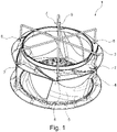
- figure 1 shows an impeller 1 in a first embodiment variant with a base disk 4, a cover disk 3 and impeller blades 5 formed axially in between in a perspective view.
- This embodiment relates to an impeller 1 designed as a radial fan with six impeller blades 5. Even if in figure 1 a bottom disk 4 is shown, impellers can also be produced without a bottom disk.
- the impeller 1 is produced from thermoplastic material using the method described in the injection molding tool using the cascade injection molding method.
- six needle shut-off nozzles 6, 7 are provided as connection positions for supplying the plastic, preferably via a hot runner system, and the supply 9 at connection positions which are equally spaced in the circumferential direction, via which the plastic is injected into the cavity of the injection molding tool.
- connection positions of the needle shut-off nozzles 6 , 7 are assigned to the cover disk 3 , ie the liquid plastic is supplied in the area that forms the cover disk 3 .
- the connection positions of the needle shut-off nozzles 6, 7 are seen in the circumferential direction between the impeller blades 5, i.e. seen in an axial projection adjacent to and not on the connecting lines of the impeller blades 5 and the cover plate 3.
- the liquid plastic thus flows over during the manufacture of the impeller 1 in Circumferentially the area of the cover plate 3, which represents the connecting lines of the impeller blades 5 and the cover plate 3.
- the needle shut-off nozzles 6, 7 are divided into two cascade groups, with the needle shut-off nozzles 6 provided with the reference number 6 forming the first group and the needle shut-off nozzles 7 provided with the reference number 7 forming the second group. Both cascade groups of the needle shut-off nozzles 6, 7 have consecutive opening times, so that the melt front of liquid plastic from the needle shut-off nozzles 6 of the first cascade group runs past the needle shut-off nozzles 7 of the second cascade group when the needle shut-off nozzles 7 of the second cascade group are opened.
- the needle shut-off nozzles 7 of the second cascade group are positioned exactly where the weld seams of the plastic supplied from the needle shut-off nozzles 6 of the first cascade group are located.
- figure 2 shows an alternative embodiment of an impeller 1.
- the features of the embodiment of figure 1 are essentially identical, but the number of impeller blades 5 and connection positions with the needle shut-off nozzles 6, 7 varies.
- the impeller 1 does not have six but only five impeller blades 5, ie an odd number.
- the number of connection points and needle shut-off nozzles 6, 7 is twice as large as the number of impeller blades 5.
- the plastic is formed over two cascade groups from the needle shut-off nozzles 6 and the needle shut-off nozzles 7 one after the other between the impeller blades 5 in cascade injection molding injected so that the weld lines are eliminated.
- the implementation of the invention is not limited to the preferred exemplary embodiments specified above. Rather, a number of variants are conceivable which make use of the solution shown even in the case of fundamentally different designs.
- the process can also be used on axial fan wheels with and without a bottom disk applicable.
- Fiber-reinforced thermoplastics can also preferably be used as plastics.
Landscapes
- Engineering & Computer Science (AREA)
- Mechanical Engineering (AREA)
- Manufacturing & Machinery (AREA)
- General Engineering & Computer Science (AREA)
- Injection Moulding Of Plastics Or The Like (AREA)
- Structures Of Non-Positive Displacement Pumps (AREA)
- Moulds For Moulding Plastics Or The Like (AREA)
Abstract
Description
- Die Erfindung betrifft ein Verfahren zum Herstellen eines Gebläserads.
- Aus dem Stand der Technik sind Gebläseräder aus Kunststoff bekannt, die im Spritzgussverfahren hergestellt werden. Derartige Kunststoffspritzgussbauteile bedürfen einer hohen Qualität, um die nötige Festigkeit für hohe Drehzahlen und die dabei entstehenden Fliehkräfte zu gewährleisten. Die Gebläseräder weisen kritische Bereiche auf, die bei Belastung zu Rissbildung neigen. Ein derartig kritischer Bereich liegt vor allem bei der die Laufradschaufel überdeckenden Deckscheibe vor.
- Da bei der Herstellung im Spritzgussverfahren Bindenähte der Kunststofffließfronten entstehen ist insbesondere im Bereich der Bindenähte das Rissbildungsrisiko hoch. Deshalb wird grundsätzlich darauf geachtet, die Bindenähte in einen möglichst spannungsarmen Bereich zu legen. Über die genormte und einzuhaltende Anbindungsauslegung des Spritzgussverfahrens und die Anzahl der benötigten Anbindungen ergibt sich eine entsprechende Anzahl an Bindenähten bei der Deckscheibe. Die Möglichkeit, diese Bindenähte in spannungsarme Bereiche zu legen ist mithin stark eingeschränkt.
- Der Erfindung liegt deshalb die Aufgabe zugrunde, ein Verfahren zur Herstellung eines Gebläserads im Kunststoffspritzgussverfahren bereit zu stellen, bei dem die Rissbildungsneigung im Bereich der Bindungsnähte reduziert ist.
- Diese Aufgabe wird durch die Merkmalskombination gemäß Patentanspruch 1 gelöst.
- Erfindungsgemäß wird ein Verfahren zur Herstellung eines Gebläserads mit einer Anzahl an Laufradschaufeln und einer die Laufradschaufeln überdeckenden Deckscheibe vorgeschlagen, bei dem das Gebläserad in einem Spritzgusswerkzeug im Kaskaden-Spritzgussverfahren aus Kunststoff gespritzt wird. Das Spritzgusswerkzeug umfasst hierzu eine Anzahl an Verschlussdüsen, insbesondere Nadelverschlussdüsen, zur Zuführung des Kunststoffs an verschiedenen Anbindungspositionen, die zur Durchführung des Kaskaden-Spritzgussverfahrens unterschiedliche Öffnungszeiten aufweisen. Die Anzahl der Verschlussdüsen wird erfindungsgemäß in Abhängigkeit von der Anzahl der Laufradschaufeln festgelegt.
- Das Kaskaden-Spritzgussverfahren ist dem Fachmann bekannt. Es handelt sich um eine Form des sequenziellen Spritzgießens, bei dem mehrere Verschlussdüsen zum Einsatz kommen, die es ermöglich, das Kunststoff-Formteil über mehrere Anschnitte zu füllen. Auch bekannt ist, für das Kaskaden-Spritzgussverfahren ein Heißkanalsystem zu verwenden, um die Kunststoffformmasse flüssig zu erhalten.
- Grundsätzlich ist das Kaskaden-Spritzgussverfahren dadurch gekennzeichnet, dass die Füllung der Kavität im Spritzgusswerkzeug besonders vorteilhaft eingestellt wird, da über eine Steuerung die Öffnungszeiten der Verschlussdüsen individuell einstellbar sind. Die Injektion des Kunststoffs in die Kavität des Spritzgusswerkzeugs findet zunächst über nur bestimmte Verschlussdüsen statt. Die sich ergebende Schmelzfront fließt und erreicht die nachgeschaltete(n) Verschlussdüse(n), die erst dann geöffnet wird bzw. werden. Die Verschlussdüsen werden also nacheinander kaskadenartig geöffnet. Die Kunststoffschmelze fließt nun über die nacheinander geöffneten Verschlussdüsen in die Kavität. Durch die Kaskadentechnik werden zum einen die Anzahl der Bindenähte reduziert, zum anderen können die Bindenähte durch die später geöffneten Verschlussdüsen durchströmt und dabei sogar vollständig eliminiert oder zumindest qualitativ deutlich verbessert werden.
- Die erfindungsgemäße Anwendung des Kaskaden-Spritzgussverfahrens zur Herstellung des Gebläserads erfolgt zur Reduzierung oder Beseitigung der Bindenähte in bezüglich der Festigkeit kritischen Bereichen an der Deckscheibe. Dabei wird die Anzahl der Verschlussdüsen in Abhängigkeit von der Anzahl der an der Deckscheibe angebundenen Laufradschaufeln festgelegt, so dass die Schmelzfront des über die Verschlussdüsen eingespritzten Kunststoffs die Verbindungsstellen zwischen der Deckscheibe und den Laufradschaufeln überfließen und über die unterschiedlichen Öffnungszeiten der Verschlussdüsen beim Kaskaden-Spritzgussverfahren keine Bindenähte an der Deckscheibe entstehen. Hierdurch wird die Festigkeit erhöht und die schwachstellenbasierte Rissbildungsneigung reduziert.
- Vorteilhaft ist einer Ausführung des Verfahrens, bei dem die verschiedenen Anbindungspositionen der Deckscheibe zugeordnet sind. Insbesondere ist günstig, wenn die verschiedenen Anbindungspositionen der Deckscheibe in der Art zugeordnet sind, dass in einer axialen Projektion gesehen, die Anbindungspositionen der Deckscheibe jeweils in Umfangsrichtung zwischen den Laufradschaufeln liegen. Entlang der Rotationsachse des Gebläserads gesehen liegen die Deckscheibe und die Laufradschaufeln axial aneinander an. Die Laufradschaufeln können geradlinig oder in Umfangsrichtung vorwärts- bzw. rückwärtsgekrümmt verlaufen. Die Anbindungspositionen werden vorzugsweise jedoch derart festgelegt, dass diese nicht auf, sondern beabstandet zu einer Verbindungslinie zwischen der Deckscheibe und den Laufradschaufeln verläuft.
- Bei dem Verfahren ist zudem in einer Ausführung vorgesehen, dass bei einer geraden Anzahl der Laufradschaufeln die Anzahl der Verschlussdüsen der Anzahl der Laufradschaufeln entspricht. Beispielsweise werden bei sechs in Umfangsrichtung an dem Gebläserad angeordneten Laufradschaufeln auch sechs Verschlussdüsen in jeweils gleichen Abstand in Umfangsrichtung vorgesehen. Somit kann sichergestellt werden, dass die Verschlussdüsen über ihre unterschiedlichen Öffnungszeiten alle Bindenähte eliminiert.
- Das Verfahren ist ferner dadurch gekennzeichnet, dass bei einer ungeraden Anzahl der Laufradschaufeln die Anzahl der Verschlussdüsen höher ist als die Anzahl der Laufradschaufeln. Insbesondere sieht ein günstiges Ausführungsbeispiel vor, dass bei einer ungeraden Anzahl der Laufradschaufeln die Anzahl der Verschlussdüsen doppelt so groß ist wie die Anzahl der Laufradschaufeln. Beispielsweise werden bei fünf in Umfangsrichtung an dem Gebläserad angeordneten Laufradschaufeln zehn Verschlussdüsen in jeweils gleichen Abstand in Umfangsrichtung vorgesehen. Somit wird ein vollständiges Durchströmen bei zeitlich versetztem Öffnen der Verschlussdüsen und mithin die Beseitigung aller Bindenähte ermöglicht.
- Eine Weiterbildung des Verfahrens ist dadurch gekennzeichnet, dass jeweils mehrere der Verschlussdüsen jeweils in Kaskadengruppen aufgeteilt sind und die Kaskadengruppen aufeinander nachfolgende Öffnungszeiten der Verschlussdüsen aufweisen. Durch die Zuordnung in Kaskadengruppen können die Öffnungszeiten der Verschlussdüsen gruppenweise über eine Steuerung gesteuert erfolgen. Das bedeutet, dass beispielsweise bei einem Gebläserad mit sechs Laufradschaufeln zunächst gleichzeitig drei von sechs Verschlussdüsen und anschließend die anderen drei Verschlussdüsen nach einem festgelegten zeitlichen Versatz öffnen, um Kunststoff in die Schmelzfront des Kunststoffs aus den zuerst geöffneten Verschlussdüsen zu injizieren und die Bindenähte zu beseitigen.
- Insbesondere ist ein Ausführungsbeispiel vorteilhaft, das dadurch gekennzeichnet ist, dass die Verschlussdüsen einer der Kaskadengruppen genau dort positioniert sind, wo Bindenähte des aus den Verschlussdüsen einer anderen Kaskadengruppe zugeführten Kunststoffs liegen. Die Anordnung der Kaskadengruppe der Verschlussdüsen erfolgt mithin auf das entsprechende Gebläserad und die jeweilige Laufradschaufelzahl genau abgestimmt.
- Das Verfahren betrifft insbesondere ein Radialgebläserad. Als Kunststoff wird vorzugsweise ein faserverstärkter Kunststoff verwendet.
- Zudem umfasst die Erfindung ein Gebläserad hergestellt nach dem vorstehend beschriebenen Verfahren mit einer optionalen Bodenscheibe, Laufradschaufeln und der Deckscheibe.
- Andere vorteilhafte Weiterbildungen der Erfindung sind in den Unteransprüchen gekennzeichnet bzw. werden nachstehend zusammen mit der Beschreibung der bevorzugten Ausführung der Erfindung anhand der Figuren näher dargestellt. Es zeigen:
- Fig. 1
- ein Gebläserad in einer ersten Ausführungsvariante in einer perspektivischen Ansicht;
- Fig. 2
- ein Gebläserad in einer zweiten Ausführungsvariante in einer perspektivischen Ansicht.
-
Figur 1 zeigt ein Gebläserad 1 in einer ersten Ausführungsvariante mit einer Bodenscheibe 4, einer Deckscheibe 3 und axial dazwischen ausgebildeten Laufradschaufeln 5 in einer perspektivischen Ansicht. Dieses Ausführungsbeispiel betrifft ein Gebläserad 1 ausgeführt als Radialgebläse mit sechs Laufradschaufeln 5. Auch wenn inFigur 1 eine Bodenscheibe 4 dargestellt ist, können auch Gebläseräder ohne Bodenscheibe hergestellt werden. - Das Gebläserad 1 ist mit dem beschriebenen Verfahren im Spritzgusswerkzeug im Kaskaden-Spritzgussverfahren aus thermoplastischem Kunststoff hergestellt. Für das Gebläserad 1 mit sechs Laufradschaufeln 5 sind sechs Nadelverschlussdüsen 6, 7 als Anbindungspositionen zur Zuführung des Kunststoffs vorzugsweise über ein Heißkanalsystem und die Zuführung 9 an in Umfangsrichtung gleich beabstandeten Anbindungspositionen vorgesehen, über welche der Kunststoff in die Kavität des Spritzgusswerkzeugs injiziert wird.
- Die Anbindungspositionen der Nadelverschlussdüsen 6, 7 sind der Deckscheibe 3 zugeordnet, das heißt die Zuführung des flüssigen Kunststoffs erfolgt in dem Bereich, der die Deckscheibe 3 bildet. Dabei liegen die Anbindungspositionen der Nadelverschlussdüsen 6, 7 in Umfangrichtung gesehen zwischen den Laufradschaufeln 5, das heißt in einer axiale Projektion gesehen benachbart zu und nicht auf den Verbindungslinien der Laufradschaufeln 5 und der Deckscheibe 3. Der flüssige Kunststoff überströmt somit beim Herstellen des Gebläserads 1 in Umfangsrichtung den Bereich der Deckscheibe 3, welcher die Verbindungslinien der Laufradschaufeln 5 und der Deckscheibe 3 darstellt.
- Die Nadelverschlussdüsen 6, 7 sind in zwei Kaskadengruppen aufgeteilt, wobei die mit dem Bezugszeichen 6 versehenen Nadelverschlussdüsen 6 die erste Gruppe und die mit dem Bezugszeichen 7 versehenen Nadelverschlussdüsen 7 die zweite Gruppe bilden. Beide Kaskadengruppen der Nadelverschlussdüsen 6, 7 weisen aufeinander nachfolgende Öffnungszeiten auf, so dass die Schmelzfront an flüssigem Kunststoff aus den Nadelverschlussdüsen 6 der ersten Kaskadengruppe an den Nadelverschlussdüsen 7 der zweiten Kaskadengruppe jeweils vorbeiläuft, wenn die Nadelverschlussdüsen 7 der zweiten Kaskadengruppe geöffnet werden. Die Nadelverschlussdüsen 7 der zweiten Kaskadengruppe sind genau dort positioniert, wo Bindenähte des aus den Nadelverschlussdüsen 6 der ersten Kaskadengruppe zugeführten Kunststoffs liegen.
-
Figur 2 zeigt ein alternatives Ausführungsbeispiel eines Gebläserads 1. Die Merkmale zu der Ausführung ausFigur 1 sind im Wesentlichen identisch, jedoch variiert die Anzahl an Laufradschaufeln 5 und Anbindungspositionen mit den Nadelverschlussdüsen 6, 7. Das Gebläserad 1 umfasst nicht sechs, sondern nur fünf Laufradschaufeln 5, d.h. eine ungerade Anzahl. Um die Bindenahtbildung in gleicher Weise wie in der Ausführung gemäßFigur 1 zu eliminieren, ist die Anzahl an Anbindungspunkten und Nadelverschlussdüsen 6, 7 doppelt so groß wie die Anzahl an Laufradschaufeln 5. Auch hier wird der Kunststoff über zwei Kaskadengruppen gebildet aus den Nadelverschlussdüsen 6 und den Nadelverschlussdüsen 7 zeitlich nacheinander zwischen den Laufradschaufeln 5 im Kaskaden-Spritzguss injiziert, so dass die Bindenähte eliminiert sind. - Die Erfindung beschränkt sich in ihrer Ausführung nicht auf die vorstehend angegebenen bevorzugten Ausführungsbeispiele. Vielmehr ist eine Anzahl von Varianten denkbar, welche von der dargestellten Lösung auch bei grundsätzlich anders gearteten Ausführungen Gebrauch macht. Beispielsweise ist das Verfahren auch auf Axialgebläseräder mit und ohne Bodenscheibe anwendbar. Auch können als Kunststoffe vorzugsweise faserverstärkte Thermoplaste eingesetzt werden.
Claims (11)
- Verfahren zur Herstellung eines Gebläserads (1) mit einer Anzahl an Laufradschaufeln (5) und einer die Laufradschaufeln (5) überdeckenden Deckscheibe (3), wobei das Gebläserad (1) in einem Spritzgusswerkzeug im Kaskaden-Spritzgussverfahren aus Kunststoff gespritzt wird und das Spritzgusswerkzeug eine Anzahl an Verschlussdüsen (6, 7) zur Zuführung des Kunststoffs an verschiedenen Anbindungspositionen aufweist, die unterschiedliche Öffnungszeiten aufweisen, wobei die Anzahl der Verschlussdüsen (6, 7) in Abhängigkeit von der Anzahl der Laufradschaufeln (5) festgelegt ist.
- Verfahren nach Anspruch 1, dadurch gekennzeichnet, dass die verschiedenen Anbindungspositionen der Deckscheibe (3) zugeordnet sind.
- Verfahren nach Anspruch 2, dadurch gekennzeichnet, dass die verschiedenen Anbindungspositionen der Deckscheibe (3) in der Art zugeordnet sind, dass in einer Projektion gesehen, die Anbindungspositionen der Deckscheibe (3) jeweils zwischen den Laufradschaufeln (5) liegen.
- Verfahren nach einem der vorigen Ansprüche, dadurch gekennzeichnet, dass bei einer geraden Anzahl der Laufradschaufeln (5) die Anzahl der Verschlussdüsen (6, 7) der Anzahl der Laufradschaufeln (5) entspricht.
- Verfahren nach einem der vorigen Ansprüche, dadurch gekennzeichnet, dass bei einer ungeraden Anzahl der Laufradschaufeln (5) die Anzahl der Verschlussdüsen (6, 7) höher ist als die Anzahl der Laufradschaufeln (5).
- Verfahren nach einem der vorigen Ansprüche, dadurch gekennzeichnet, dass bei einer ungeraden Anzahl der Laufradschaufeln (5) die Anzahl der Verschlussdüsen (6, 7) doppelt so groß ist wie die Anzahl der Laufradschaufeln (5).
- Verfahren nach einem der vorigen Ansprüche, dadurch gekennzeichnet, dass jeweils mehrere der Verschlussdüsen (6, 7) jeweils in Kaskadengruppen aufgeteilt sind und die Kaskadengruppen aufeinander nachfolgende Öffnungszeiten der Verschlussdüsen (6, 7) aufweisen.
- Verfahren nach dem vorigen Anspruch, dadurch gekennzeichnet, dass die Verschlussdüsen (6, 7) einer der Kaskadengruppen dort positioniert sind, wo Bindenähte des aus den Verschlussdüsen (6, 7) einer anderen Kaskadengruppe zugeführten Kunststoffs liegen.
- Verfahren nach einem der vorigen Ansprüche, dadurch gekennzeichnet, dass das Gebläserad (1) ein Radialgebläserad ist.
- Verfahren nach einem der vorigen Ansprüche, dadurch gekennzeichnet, dass der Kunststoff ein faserverstärkter Kunststoff ist.
- Gebläserad (1) hergestellt nach dem Verfahren nach einem der vorigen Ansprüche.
Applications Claiming Priority (1)
| Application Number | Priority Date | Filing Date | Title |
|---|---|---|---|
| DE102020127199.9A DE102020127199A1 (de) | 2020-10-15 | 2020-10-15 | Verfahren zum Herstellen eines Gebläserads |
Publications (3)
| Publication Number | Publication Date |
|---|---|
| EP3984719A1 true EP3984719A1 (de) | 2022-04-20 |
| EP3984719B1 EP3984719B1 (de) | 2025-08-20 |
| EP3984719C0 EP3984719C0 (de) | 2025-08-20 |
Family
ID=77710679
Family Applications (1)
| Application Number | Title | Priority Date | Filing Date |
|---|---|---|---|
| EP21196052.1A Active EP3984719B1 (de) | 2020-10-15 | 2021-09-10 | Verfahren zum herstellen eines gebläserads |
Country Status (4)
| Country | Link |
|---|---|
| US (1) | US12109746B2 (de) |
| EP (1) | EP3984719B1 (de) |
| CN (1) | CN114368116B (de) |
| DE (1) | DE102020127199A1 (de) |
Citations (4)
| Publication number | Priority date | Publication date | Assignee | Title |
|---|---|---|---|---|
| JP2003094494A (ja) * | 2001-09-25 | 2003-04-03 | Denso Corp | ファン及びその成形方法 |
| US20060290030A1 (en) * | 2005-06-28 | 2006-12-28 | Denso Corporation | Manufacture method for molded product |
| US20070104581A1 (en) * | 2004-04-26 | 2007-05-10 | Borgwarner Inc. | Plastic fans having improved fan ring weld line strength |
| DE102016207545A1 (de) * | 2016-05-02 | 2017-11-02 | Mahle International Gmbh | Lüfterrad |
Family Cites Families (8)
| Publication number | Priority date | Publication date | Assignee | Title |
|---|---|---|---|---|
| DE10350417A1 (de) * | 2003-10-28 | 2005-06-02 | Behr Gmbh & Co. Kg | Verfahren zur Herstellung eines Lüfterrades sowie nach diesem Verfahren hergestelltes Lüfterrad |
| CN101077608B (zh) * | 2007-03-23 | 2010-12-22 | 台达电子零组件(东莞)有限公司 | 用于射出成型叶轮的模具总成、方法及所形成的叶轮 |
| DE102009012082B3 (de) * | 2009-03-06 | 2010-10-28 | Incoe International, Inc. | Verfahren zum Spritzgießen, insbesondere zum Kaskadenspritzgießen, und Vorrichtung zur Durchführung des Verfahrens |
| DE102010014487A1 (de) | 2010-04-10 | 2011-10-13 | Sensus Spectrum Llc | Verfahren zum Herstellen von ringförmigen, zug- oder druckbelasteten Formkörpern aus Kunststoff |
| CN202646149U (zh) * | 2012-05-24 | 2013-01-02 | 王保华 | 风叶 |
| CN106541542A (zh) * | 2015-09-16 | 2017-03-29 | 柳道(青岛)热流道系统有限公司 | 热流道系统及其注塑工艺 |
| DE102015223585A1 (de) * | 2015-11-27 | 2017-06-01 | BSH Hausgeräte GmbH | Verfahren zum Herstellen eines Haushaltsgerätebauteils in einem kombinierten Spritzgussprozess mit einem Dünnwandspritzgießen und einem Kaskaden-Spritzgießen sowie Haushaltsgerätebauteil |
| DE102017215570A1 (de) * | 2017-09-05 | 2019-03-07 | Robert Bosch Gmbh | Spritzgussverfahren zum Herstellen eines Lüfters mit verbesserter Bindenahtfestigkeit |
-
2020
- 2020-10-15 DE DE102020127199.9A patent/DE102020127199A1/de active Pending
-
2021
- 2021-09-10 EP EP21196052.1A patent/EP3984719B1/de active Active
- 2021-10-09 CN CN202111175061.8A patent/CN114368116B/zh active Active
- 2021-10-12 US US17/498,801 patent/US12109746B2/en active Active
Patent Citations (4)
| Publication number | Priority date | Publication date | Assignee | Title |
|---|---|---|---|---|
| JP2003094494A (ja) * | 2001-09-25 | 2003-04-03 | Denso Corp | ファン及びその成形方法 |
| US20070104581A1 (en) * | 2004-04-26 | 2007-05-10 | Borgwarner Inc. | Plastic fans having improved fan ring weld line strength |
| US20060290030A1 (en) * | 2005-06-28 | 2006-12-28 | Denso Corporation | Manufacture method for molded product |
| DE102016207545A1 (de) * | 2016-05-02 | 2017-11-02 | Mahle International Gmbh | Lüfterrad |
Also Published As
| Publication number | Publication date |
|---|---|
| US12109746B2 (en) | 2024-10-08 |
| CN114368116B (zh) | 2024-12-20 |
| CN114368116A (zh) | 2022-04-19 |
| US20220118663A1 (en) | 2022-04-21 |
| EP3984719B1 (de) | 2025-08-20 |
| EP3984719C0 (de) | 2025-08-20 |
| DE102020127199A1 (de) | 2022-04-21 |
Similar Documents
| Publication | Publication Date | Title |
|---|---|---|
| DE3523516C2 (de) | Verfahren zur Herstellung eines Verdichterrotors | |
| DE102013201871C5 (de) | Vortexgenerator für ein Rotorblatt einer Windenergieanlage | |
| DE102009046164A1 (de) | Verfahren zur Herstellung eines Mehrkomponenten-Wischerarms | |
| DE3501433A1 (de) | Nockenwelle und verfahren zur herstellung derselben | |
| DE1812994A1 (de) | Verfahren und Vorrichtung zur Herstellung eines faserverstaerkten Verbundkoerpers | |
| DE102014015870B4 (de) | Fahrwerksbauteil für ein Kraftfahrzeug aus einem kurzfaserverstärkten Kunststoff | |
| DE69511177T2 (de) | Verfahren zur Herstellung eines elektrischen Haushaltschlagbesens und nach diesem Verfahren hergestellter Schlagbesen | |
| DE1912619A1 (de) | Verfahren zur Herstellung eines beschaufelten Rotors | |
| DE102019009151B3 (de) | Schmelzeverteiler | |
| EP3724512B1 (de) | Gehäuse hergestellt in einem arbeitsgang | |
| EP3984719B1 (de) | Verfahren zum herstellen eines gebläserads | |
| DE102020103047A1 (de) | Anspritzwerkzeug und Verfahren zum Herstellen eines Rotors | |
| DE4234292A1 (de) | Axiallüfter mit Kuststoffschaufeln | |
| EP3678828B1 (de) | Spritzgussverfahren zum herstellen eines lüfters mit verbesserter bindenahtfestigkeit | |
| DE102012208363A1 (de) | Hohles Bauteil sowie Vorrichtung und Verfahren zu dessen Herstellung | |
| DE102019103920A1 (de) | Verfahren zur Herstellung eines Rotors für einen Elektromotor sowie Rotor für einen Elektromotor | |
| DE19908846A1 (de) | Verfahren zur Fertigung von Kunststofformteilen mit thermisch höher belasteten Segmenten | |
| DE2062053A1 (de) | Stromlinienförmig gestaltete Schaufel fur eine Stromungsmaschine | |
| EP3778179A1 (de) | Verfahren und vorrichtung zur herstellung eines bauteils | |
| EP2706271A1 (de) | Faltenbalg und Verfahren zur Herstellung eines Faltenbalges | |
| DE4204973A1 (de) | Verfahren zum herstellen einer gelenkscheibe sowie eine gelenkscheibe zum verbinden von wellenflanschen | |
| DE4014400A1 (de) | Verfahren zur herstellung von anschlussflanschen fuer rohre aus faserverstaerktem kunststoffmaterial, insbesondere transaxlerohre oder dergleichen fuer kraftfahrzeuge | |
| DE102018132079A1 (de) | Diagonalventilatorrad hergestellt in einem Arbeitsgang | |
| DE202012103569U1 (de) | Vorrichtung zur Herstellung textilverstärkter Kunststoffbauteile | |
| DE19519873C1 (de) | Vorrichtung zur Herstellung eines rotationssymmetrischen Formteils |
Legal Events
| Date | Code | Title | Description |
|---|---|---|---|
| PUAI | Public reference made under article 153(3) epc to a published international application that has entered the european phase |
Free format text: ORIGINAL CODE: 0009012 |
|
| STAA | Information on the status of an ep patent application or granted ep patent |
Free format text: STATUS: THE APPLICATION HAS BEEN PUBLISHED |
|
| AK | Designated contracting states |
Kind code of ref document: A1 Designated state(s): AL AT BE BG CH CY CZ DE DK EE ES FI FR GB GR HR HU IE IS IT LI LT LU LV MC MK MT NL NO PL PT RO RS SE SI SK SM TR |
|
| STAA | Information on the status of an ep patent application or granted ep patent |
Free format text: STATUS: REQUEST FOR EXAMINATION WAS MADE |
|
| 17P | Request for examination filed |
Effective date: 20221018 |
|
| RBV | Designated contracting states (corrected) |
Designated state(s): AL AT BE BG CH CY CZ DE DK EE ES FI FR GB GR HR HU IE IS IT LI LT LU LV MC MK MT NL NO PL PT RO RS SE SI SK SM TR |
|
| STAA | Information on the status of an ep patent application or granted ep patent |
Free format text: STATUS: EXAMINATION IS IN PROGRESS |
|
| 17Q | First examination report despatched |
Effective date: 20230417 |
|
| GRAP | Despatch of communication of intention to grant a patent |
Free format text: ORIGINAL CODE: EPIDOSNIGR1 |
|
| STAA | Information on the status of an ep patent application or granted ep patent |
Free format text: STATUS: GRANT OF PATENT IS INTENDED |
|
| RIC1 | Information provided on ipc code assigned before grant |
Ipc: B29L 31/08 20060101ALN20250327BHEP Ipc: B29C 45/00 20060101ALI20250327BHEP Ipc: B29C 45/27 20060101AFI20250327BHEP |
|
| INTG | Intention to grant announced |
Effective date: 20250409 |
|
| GRAS | Grant fee paid |
Free format text: ORIGINAL CODE: EPIDOSNIGR3 |
|
| GRAA | (expected) grant |
Free format text: ORIGINAL CODE: 0009210 |
|
| STAA | Information on the status of an ep patent application or granted ep patent |
Free format text: STATUS: THE PATENT HAS BEEN GRANTED |
|
| AK | Designated contracting states |
Kind code of ref document: B1 Designated state(s): AL AT BE BG CH CY CZ DE DK EE ES FI FR GB GR HR HU IE IS IT LI LT LU LV MC MK MT NL NO PL PT RO RS SE SI SK SM TR |
|
| REG | Reference to a national code |
Ref country code: GB Ref legal event code: FG4D Free format text: NOT ENGLISH |
|
| REG | Reference to a national code |
Ref country code: CH Ref legal event code: EP |
|
| REG | Reference to a national code |
Ref country code: IE Ref legal event code: FG4D Free format text: LANGUAGE OF EP DOCUMENT: GERMAN |
|
| REG | Reference to a national code |
Ref country code: DE Ref legal event code: R096 Ref document number: 502021008380 Country of ref document: DE |
|
| U01 | Request for unitary effect filed |
Effective date: 20250820 |
|
| U07 | Unitary effect registered |
Designated state(s): AT BE BG DE DK EE FI FR IT LT LU LV MT NL PT RO SE SI Effective date: 20250827 |
|
| U20 | Renewal fee for the european patent with unitary effect paid |
Year of fee payment: 5 Effective date: 20250827 |
|
| PG25 | Lapsed in a contracting state [announced via postgrant information from national office to epo] |
Ref country code: IS Free format text: LAPSE BECAUSE OF FAILURE TO SUBMIT A TRANSLATION OF THE DESCRIPTION OR TO PAY THE FEE WITHIN THE PRESCRIBED TIME-LIMIT Effective date: 20251220 |
|
| PG25 | Lapsed in a contracting state [announced via postgrant information from national office to epo] |
Ref country code: NO Free format text: LAPSE BECAUSE OF FAILURE TO SUBMIT A TRANSLATION OF THE DESCRIPTION OR TO PAY THE FEE WITHIN THE PRESCRIBED TIME-LIMIT Effective date: 20251120 |
|
| PG25 | Lapsed in a contracting state [announced via postgrant information from national office to epo] |
Ref country code: HR Free format text: LAPSE BECAUSE OF FAILURE TO SUBMIT A TRANSLATION OF THE DESCRIPTION OR TO PAY THE FEE WITHIN THE PRESCRIBED TIME-LIMIT Effective date: 20250820 |
|
| PG25 | Lapsed in a contracting state [announced via postgrant information from national office to epo] |
Ref country code: GR Free format text: LAPSE BECAUSE OF FAILURE TO SUBMIT A TRANSLATION OF THE DESCRIPTION OR TO PAY THE FEE WITHIN THE PRESCRIBED TIME-LIMIT Effective date: 20251121 |
|
| PG25 | Lapsed in a contracting state [announced via postgrant information from national office to epo] |
Ref country code: PL Free format text: LAPSE BECAUSE OF FAILURE TO SUBMIT A TRANSLATION OF THE DESCRIPTION OR TO PAY THE FEE WITHIN THE PRESCRIBED TIME-LIMIT Effective date: 20250820 |
|
| PG25 | Lapsed in a contracting state [announced via postgrant information from national office to epo] |
Ref country code: RS Free format text: LAPSE BECAUSE OF FAILURE TO SUBMIT A TRANSLATION OF THE DESCRIPTION OR TO PAY THE FEE WITHIN THE PRESCRIBED TIME-LIMIT Effective date: 20251120 |
|
| PG25 | Lapsed in a contracting state [announced via postgrant information from national office to epo] |
Ref country code: ES Free format text: LAPSE BECAUSE OF FAILURE TO SUBMIT A TRANSLATION OF THE DESCRIPTION OR TO PAY THE FEE WITHIN THE PRESCRIBED TIME-LIMIT Effective date: 20250820 |
|
| PG25 | Lapsed in a contracting state [announced via postgrant information from national office to epo] |
Ref country code: SM Free format text: LAPSE BECAUSE OF FAILURE TO SUBMIT A TRANSLATION OF THE DESCRIPTION OR TO PAY THE FEE WITHIN THE PRESCRIBED TIME-LIMIT Effective date: 20250820 |
|
| PG25 | Lapsed in a contracting state [announced via postgrant information from national office to epo] |
Ref country code: CZ Free format text: LAPSE BECAUSE OF FAILURE TO SUBMIT A TRANSLATION OF THE DESCRIPTION OR TO PAY THE FEE WITHIN THE PRESCRIBED TIME-LIMIT Effective date: 20250820 |
|
| REG | Reference to a national code |
Ref country code: CH Ref legal event code: H13 Free format text: ST27 STATUS EVENT CODE: U-0-0-H10-H13 (AS PROVIDED BY THE NATIONAL OFFICE) Effective date: 20260425 |
|
| PG25 | Lapsed in a contracting state [announced via postgrant information from national office to epo] |
Ref country code: SK Free format text: LAPSE BECAUSE OF FAILURE TO SUBMIT A TRANSLATION OF THE DESCRIPTION OR TO PAY THE FEE WITHIN THE PRESCRIBED TIME-LIMIT Effective date: 20250820 |