EP3984019B1 - Hochleistungsschallerzeugungssystem für fahrzeuge - Google Patents
Hochleistungsschallerzeugungssystem für fahrzeuge Download PDFInfo
- Publication number
- EP3984019B1 EP3984019B1 EP20730669.7A EP20730669A EP3984019B1 EP 3984019 B1 EP3984019 B1 EP 3984019B1 EP 20730669 A EP20730669 A EP 20730669A EP 3984019 B1 EP3984019 B1 EP 3984019B1
- Authority
- EP
- European Patent Office
- Prior art keywords
- sound
- guide
- vehicle
- electro
- membrane
- Prior art date
- Legal status (The legal status is an assumption and is not a legal conclusion. Google has not performed a legal analysis and makes no representation as to the accuracy of the status listed.)
- Active
Links
Images


Classifications
-
- G—PHYSICS
- G10—MUSICAL INSTRUMENTS; ACOUSTICS
- G10K—SOUND-PRODUCING DEVICES; METHODS OR DEVICES FOR PROTECTING AGAINST, OR FOR DAMPING, NOISE OR OTHER ACOUSTIC WAVES IN GENERAL; ACOUSTICS NOT OTHERWISE PROVIDED FOR
- G10K9/00—Devices in which sound is produced by vibrating a diaphragm or analogous element, e.g. fog horns, vehicle hooters or buzzers
- G10K9/12—Devices in which sound is produced by vibrating a diaphragm or analogous element, e.g. fog horns, vehicle hooters or buzzers electrically operated
-
- G—PHYSICS
- G10—MUSICAL INSTRUMENTS; ACOUSTICS
- G10K—SOUND-PRODUCING DEVICES; METHODS OR DEVICES FOR PROTECTING AGAINST, OR FOR DAMPING, NOISE OR OTHER ACOUSTIC WAVES IN GENERAL; ACOUSTICS NOT OTHERWISE PROVIDED FOR
- G10K11/00—Methods or devices for transmitting, conducting or directing sound in general; Methods or devices for protecting against, or for damping, noise or other acoustic waves in general
- G10K11/18—Methods or devices for transmitting, conducting or directing sound
- G10K11/22—Methods or devices for transmitting, conducting or directing sound for conducting sound through hollow pipes, e.g. speaking tubes
-
- H—ELECTRICITY
- H04—ELECTRIC COMMUNICATION TECHNIQUE
- H04R—LOUDSPEAKERS, MICROPHONES, GRAMOPHONE PICK-UPS OR LIKE ACOUSTIC ELECTROMECHANICAL TRANSDUCERS; ELECTRIC HEARING AIDS; PUBLIC ADDRESS SYSTEMS
- H04R1/00—Details of transducers, loudspeakers or microphones
- H04R1/20—Arrangements for obtaining desired frequency or directional characteristics
- H04R1/32—Arrangements for obtaining desired frequency or directional characteristics for obtaining desired directional characteristic only
- H04R1/34—Arrangements for obtaining desired frequency or directional characteristics for obtaining desired directional characteristic only by using a single transducer with sound reflecting, diffracting, directing or guiding means
- H04R1/345—Arrangements for obtaining desired frequency or directional characteristics for obtaining desired directional characteristic only by using a single transducer with sound reflecting, diffracting, directing or guiding means for loudspeakers
-
- B—PERFORMING OPERATIONS; TRANSPORTING
- B60—VEHICLES IN GENERAL
- B60Q—ARRANGEMENT OF SIGNALLING OR LIGHTING DEVICES, THE MOUNTING OR SUPPORTING THEREOF OR CIRCUITS THEREFOR, FOR VEHICLES IN GENERAL
- B60Q5/00—Arrangement or adaptation of acoustic signal devices
- B60Q5/005—Arrangement or adaptation of acoustic signal devices automatically actuated
-
- H—ELECTRICITY
- H04—ELECTRIC COMMUNICATION TECHNIQUE
- H04R—LOUDSPEAKERS, MICROPHONES, GRAMOPHONE PICK-UPS OR LIKE ACOUSTIC ELECTROMECHANICAL TRANSDUCERS; ELECTRIC HEARING AIDS; PUBLIC ADDRESS SYSTEMS
- H04R2201/00—Details of transducers, loudspeakers or microphones covered by H04R1/00 but not provided for in any of its subgroups
- H04R2201/34—Directing or guiding sound by means of a phase plug
-
- H—ELECTRICITY
- H04—ELECTRIC COMMUNICATION TECHNIQUE
- H04R—LOUDSPEAKERS, MICROPHONES, GRAMOPHONE PICK-UPS OR LIKE ACOUSTIC ELECTROMECHANICAL TRANSDUCERS; ELECTRIC HEARING AIDS; PUBLIC ADDRESS SYSTEMS
- H04R2499/00—Aspects covered by H04R or H04S not otherwise provided for in their subgroups
- H04R2499/10—General applications
- H04R2499/13—Acoustic transducers and sound field adaptation in vehicles
Definitions
- the present invention relates to a sound generating system for vehicles that is used for generating a sound with maximum efficiency and minimum volume, as well as for achieving high sound values and in particular for reproducing a typical sound generated by the exhaust gases of an internal combustion engine that are emitted from an exhaust pipe of the vehicle.
- Some automotive manufacturers need to achieve high sound levels outside the vehicle to simulate or improve the sound level produced by the exhaust of the combustion fumes of the internal combustion engine of the vehicle. For example, in the most extreme example, some automotive manufacturers need to achieve sound levels of 130 - 135 dB at 30 cm from the mouth of the exhaust of the vehicle, with the microphone orientated at 45° (in this case, dBre20 ⁇ Pa).
- the sound produced by the exhaust may be dramatically reduced in such a way to eliminate the sound-vehicle association that characterizes the vehicle category and consequently the value of the vehicle in terms of performance and value.
- the sound-vehicle association is changing dramatically because of the progressive introduction of electric vehicles, wherein the sound produced by the exhaust and the sound produced by the engine no longer exist.
- automotive manufacturers would like to maintain said sound-vehicle association as long as possible.
- the only solution to remedy such a technical problem is to use an audio reproduction, namely to reproduce a sound that increases, in case of vehicles with internal combustion engine, or synthesizes, in case of electric vehicles, the typical sound produced by the emission of the exhaust gases of an internal combustion engine.
- the audio reproduction is performed with a system of electro-acoustic transducers (loudspeakers) controlled by a suitably processed and amplified signal.
- the system should be able to generate an external sound with maximum efficiency and maximum frequency extension.
- the loudspeakers with direct radiation that are traditionally used in vehicles for reproducing the audio signal in the vehicle compartment cannot achieve a high directive sound level that is similar and capable of replacing the sound level generated by the emission of exhaust gases from the vehicle silencer. Therefore, lower sound levels, higher volumes, poor directivity and high power consumption must be accepted.
- US2014/328494 discloses a sound generating system that comprises a sound generator disposed in the vehicle and a sound emission tube that partially comes out of the vehicle. The document does not disclose that a single electro-acoustic transducer is connected to two acoustic wave-guides.
- US2010/245069 discloses the generation of a sound that simulates the noise of an engine and the propagation of said sound through a wave-guide partially outside the vehicle.
- DE102017203184 discloses the generation of an artificial exhaust noise to imitate the exhaust system of a vehicle.
- DE 102017210688 discloses the generation of an artificial noise of a vehicle engine according to parameters detected by an ECU.
- US6038326 discloses different types of horns for electromechanical transducers.
- US2015/373445 discloses a horn with dome-shaped membrane, phase-plug and wave-guide.
- US2018/020290 discloses an audio system for vehicles of infinite baffle type.
- the purpose of the present invention is to eliminate the drawbacks of the prior art by disclosing a sound generating system for vehicles that is capable of simulating the typical sound generated by the emission of exhaust gases from the silencer of an internal combustion engine, in an efficacious, effective and accurate way.
- Another purpose of the present invention is to provide such a sound generating system for vehicles characterized by higher efficiency and consequently lower power consumption, as well as a defined emission in the space (controlled directivity), compared to the sound generating systems of the prior art.
- the applicant performed several experimental tests, in the attempt to reproduce the sound generated by the emission of exhaust gases from the silencer of an internal combustion engine, using different types of loudspeakers with direct radiation in different positions of the vehicle.
- said experimental tests were not satisfactory in terms of sound level and spatial distribution compared to the real sound generated by the emission of the exhaust gases from the silencer of an internal combustion motor.
- the applicant decided to use a technique to improve and control the spatial emission of the electro-acoustic transducers that are normally used, namely transducers with direct radiation and also suitable transducers that use a horn loading technique.
- the horn loading technique controls the directivity and the efficiency of the emission through an especially designed wave-guide or horn.
- the applicant demonstrated the advantageous use of compression drivers associated with a wave-guide conduit or horn (Horn Compression Driver).
- a sound pressure level (SPL) of 130 dB was achieved and exceeded, using an electrical power lower than 200W.
- the sound level can be increased and the transfer function band can be extended; moreover, the directivity of the source can be improved by disposing a horn load or wave-guide in front of the membrane of the transducer.
- the wave-guide by suitably designing the wave-guide, very high sound pressure levels can be achieved in a limited space, thus modifying the directivity.
- the design of the wave-guide comprises the application of a given compression level of the air in front of the emission membrane of the transducer.
- the compressed air is conveyed in the wave-guide through a device, known in the prior art as phase-plug, which minimizes the generation of turbulence and, most of all, makes the path of the acoustic waves produced by each portion of the surface of the membrane practically equivalent, adding them and creating a flat wave front in the conduit of the wave-guide.
- a device known in the prior art as phase-plug, which minimizes the generation of turbulence and, most of all, makes the path of the acoustic waves produced by each portion of the surface of the membrane practically equivalent, adding them and creating a flat wave front in the conduit of the wave-guide.
- US2037187 discloses such a type of phase-plug composed of a plurality of conical elements disposed coaxially one inside the other. The effect of said device increases when the frequency of the signal to be transduced increases, also depending on the dimensions
- the square area A represents a vehicle, and the perimeter divides the interior from the exterior of the vehicle.
- a sound generating system (100), which is not part of the invention, comprises:
- the electro-acoustic transducer (B) is disposed in the vehicle (A). A portion of the acoustic wave-guide (C) lies inside the vehicle (A), and another portion of the acoustic wave-guide (C) lies outside the vehicle, where the sound is emitted.
- a phase-plug (R) is disposed between the electro-acoustic transducer (B) and the acoustic wave-guide (C).
- the complexity (geometric configuration and number of radial or concentric conduits) of the phase-plug (R) depends on the maximum frequency to be reproduced.
- a second embodiment of a sound generating system is disclosed, which is indicated with reference numeral 200.
- the sound generating system (200) provides for adding a second acoustic wave-guide (D) in the vehicle (A), said second acoustic wave-guide (D) being connected in one side of the electro-acoustic transducer (B) in opposite position to the side where the first wave-guide (C) that goes outwards is connected.
- the second wave-guide (D) emits the sound inside the vehicle. In this way, because of the provision of the second wave-guide (D), the sound can be emitted in the internal compartment of the vehicle.
- An acoustic damper (E) is disposed in the second wave-guide (D).
- a phase-plug (R) is disposed between the electro-acoustic transducer (B) and the second wave-guide (D).
- Fig. 3 shows an embodiment of the electro-acoustic transducer (B) that consists in a compression driver (B1).
- the compression driver (B1) comprises a membrane (1) connected to a voice coil (2) arranged in an air gap with a magnetic field generated by a magnetic unit (3).
- the magnetic unit (3) comprises a magnet (30) disposed between a yoke (4) and an upper pole plate (31).
- the yoke (4) has a shank (40) disposed inside the voice coil (2).
- a spider (5) is connected to the magnetic unit (3) and to the voice coil (2) in order to center the voice coil (2) in the air gap.
- the membrane (1) has a dome-like shape or a tapered shape in such a way to define a concave surface directed towards an output duct (O) obtained in the yoke (4) of the magnetic unit.
- the shank (40) of the yoke has a convex surface (41) directed towards the concave surface of the membrane (1).
- the convex surface (41) of the shank is provided with a plurality of openings that act as phase-plug and are in communication with passages (42) that end in the output duct (O) for the emission of sound.
- Fig. 4 shows a second embodiment of the electro-acoustic transducer (B) that consists in a compression driver (B2), wherein the output duct (O) is directed towards the convex surface of the membrane (1).
- the output duct (O) is obtained in a support (6) disposed on the upper pole plate (31) of the magnetic unit.
- the support (6) has a concave surface (61) directed towards the convex surface of the membrane (1).
- the concave surface (61) of the support is provided with a plurality of openings that are in communication with passages (62) that end in the output duct (O) for the emission of sound.
- the voice coil (2) is insulated from the external environment, thus reducing the risks of damage caused by the introduction of water eater or dust.
- the configuration of Fig. 4 is more advantageous for automotive applications, where weather agents may damage the electro-acoustic transducer (B).
- Fig. 4A shows a variant of the compression driver (B2) of Fig. 4 , which improves the behavior at low frequencies.
- a dome-shaped enclosure (9) is mounted under the magnetic unit (3) in such a way to form a rear chamber (90).
- the yoke (4) has a through axial duct (45) that puts the rear chamber (90) in communication with a front chamber (91) formed above the shank (40) of the yoke, between the shank (40) of the yoke and the dome-shaped membrane (1).
- the rear chamber (90) acts as resonator and improves the performance at low frequencies.
- Fig. 4B shows an additional variant of the compression driver (B2) of Fig. 4A , which uses the rear chamber (90) in communication with the output duct (O) of the compression driver (B2) by means of peripheral conduits (92).
- the peripheral conduits (92) pass externally with respect to the magnetic unit (3) and the support (6).
- Fig. 5 is a chart that shows the frequency response of a compression driver available on the market, with the application of a wave-guide.
- Fig. 5 shows the values of the sound pressure level (SPL) detected in an anechoic chamber and the impedance values upon a frequency variation, with such a constant voltage that 1 Wrms is obtained on electric resistance equivalent to the rated impedance.
- the SPL is approximately 110 dB in a frequency range from 500 to 3,000 Hz.
- the electro-acoustic transducer (B) can be an ordinary loudspeaker with direct radiation.
- the loudspeaker has lower operating frequencies than the compression driver and the wave-guide (C) applied to the loudspeaker has higher dimensions (for example, a rectangular outlet with 60cm x 40cm size) compared to the use of a compression driver.
- loudspeakers that are defined as "Midrange” can be used, with a diameter of the membrane of 10 inches (approximately 250 mm).
- Fig. 8 shows an example of phase-plug (R).
- the phase-plug (R) is suitable for being applied on the output duct of a compression driver or in front of the membrane of a loudspeaker in order to increase the uniformity and the linearity of the coupling to a horn or wave-guide.
- Fig. 8 shows an example of phase-plug (R) for loudspeaker with direct radiation that comprises a collar (7) connected to a central portion (73) by means of a plurality of radial spokes (71) in such a way to define a plurality of slots (72).
- Fig. 8 shows five slots (72).
- the central portion (70) of the phase-plug is usually provided with a truncated-conical shape in order to be inserted in the groove of a horn or wave-guide with a plurality of longitudinal grooves (73).
- phase-plug for compression drivers is disclosed in US2037187 , which illustrates a plurality of conical elements that are disposed coaxially one inside the other.
- the main parameters of a wave-guide are: its length, the surface of the mouth for emission towards the exterior, and the variation of the transverse surface between the inlet groove and the outlet. These parameters define the pass band and the efficiency of acoustic energy transmission.
- the geometrical development of the wave-guide can be deformed, namely the wave-guide can be bent and can have a path that is not exactly straight, while still operating in a correct, acceptable way.
- Fig. 9 shows a first embodiment of a wave-guide (C1).
- the wave-guide (C1) has a circular inlet groove (8) in communication with a cylindrical conduit (84) that is coaxially disposed inside a second conduit (85) with an upper wall (86) with a flow deflector that radially divides the air flow (F) that reaches the upper wall (86).
- the two conduits (84, 85) are disposed inside the body (81) of the wave-guide that defines a channel (83) with truncated-pyramidal shape and square or rectangular section, which ends in the outlet (82) with square or rectangular shape.
- the second conduit (84) is open on the bottom in such a way that the air flow (F) can flow in the conduit (83) of the body of the wave-guide and leave from the outlet (82) with square or rectangular shape. So, the air flow (F) follows an S-shaped tortuous path from the inlet groove (8) towards the outlet (82). In view of the above, the introduction of external elements in the inlet groove (8) is prevented.
- Fig. 10 illustrates a second embodiment of a wave-guide (C2), wherein the body (81) that defines the channel (83) from the inlet groove (8) to the outlet (82) has a tapered, curved shape.
- Fig. 11 illustrates a third embodiment of a wave-guide (C3), wherein the body (81) that defines the channel (83) from the inlet groove (8) to the outlet (82) has a tapered shape with a 180° curve. Moreover, the axis of the inlet groove (8) and the axis of the outlet (82) are staggered.
- the body (81) of the wave-guide has an inclination from the bottom upwards, going from the outlet (82) to the inlet groove (8).
- the positioning at 180° between the inlet groove (8) and the outlet (82) can break a water jet during a washing cycle with a pressure washer (the high pressure of the pressure washer might damage the transducer), whereas the inclination between the inlet groove (8) and the outlet (82) prevents the accumulation and stagnation of water.
- a transducer with a wave-guide is an additional advantage in terms of installation in a vehicle because the wave-guide protects the transducer against the weather agents.
- the wave-guide can be modeled in such a way to be integrated with the aerodynamics of the vehicle, emitting the sound from parts of the vehicle that are not visible (for example, behind grilles in the back or in the front bumper of the vehicle).
- the wave-guide can be extremely flat and mounted immediately under the underbody of the vehicle, following its curvature, without hindering the air flow that flows under the underbody of the vehicle while traveling, without changing the aerodynamics of the vehicle.
- Another solution is to emit the sound also from the rear portion of the electro-acoustic transducer and convey the second emission towards the interior of the vehicle with a wave-guide.
- Another solution that is suitable for increasing the sound pressure of the wave-guide at low frequencies consists in positioning the outlet in the underbody of the vehicle in such a way to create an acoustic load provided by the air gap between the underbody of the vehicle and the tread. Moreover, the closeness to the tread would result in the emission of a semi-spherical acoustic field.
- the system of the invention maximizes the transduction efficiency with minimum power consumption. If significant sound pressure levels (SPL higher than 120dB) are not necessary, the power is reduced, and the system of the invention can be applied to electric vehicles to create a sound for safety and marketing reasons, in order to give a specific sound identity to each type of vehicle.
- SPL higher than 120dB significant sound pressure levels
- Fig. 12 which is not part of the invention, illustrates the installation of an electro-acoustic transducer (B) in the vehicle (A), in the form of a compression driver that can be integrated in the trunk in the back of the vehicle, in such a way to emit the sound from the back of the vehicle.
- the electro-acoustic transducer (B) is associated with an acoustic wave-guide (C) that passes through the body of the vehicle and has an outlet (82) that ends in the back of the body of the vehicle and is covered with a grille (120) installed in a rear bumper (121) of the vehicle.
- Fig. 13 which is not part of the invention, illustrates the installation of an electro-acoustic transducer (B) in the vehicle (A), in the form of a loudspeaker that is disposed in the front hood of the vehicle.
- the electro-acoustic transducer (B) is associated with an acoustic wave-guide (C) that follows the bottom of the body of the vehicle, keeping the curvature with the minimum effect on the air flow (lower aerodynamic resistance).
- the acoustic wave-guide (C) passes through the body of the vehicle and has an outlet (82) disposed on the outside of the vehicle and directed, for instance, towards the rear wheels of the vehicle.
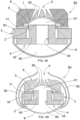
- Fig. 14 which is not part of the invention, illustrates two electro-acoustic transducers (B) disposed in the trunk of the vehicle and coupled with two wave-guides (C) that come out from the bottom of the vehicle body, such as two silencers, simulating the form and the sound of the silencer(s) of the vehicle.
- B electro-acoustic transducers
- C wave-guides
- Fig. 15 which is not part of the invention, illustrates a signal processing system that can be used in the sound generating system (100; 200) of the invention.
- a signal processing system can be substantially similar to the one described in detail in the patent No. US9686611 in the name of the same applicant ASK INDUSTRIES SOCIET ⁇ PER AZIONI .
- the vehicle (A) has an internal combustion engine (M) whereon a vibration sensor (101), such as an inertial vibration loudspeaker (shaker or exciter), is mounted (101).
- a vibration sensor such as an inertial vibration loudspeaker (shaker or exciter)
- the shaker (101) is electrically connected to a digital signal processor (DSP) (102) to provide information on the vibrations of the engine (M).
- DSP digital signal processor
- An electronic control unit (ECU) (103) of the vehicle is connected to the DSP (102) by means of a Can-bus (104) and a Can interface (105) to provide information on parameters of the vehicle, such as number of engine revolutions, engine torque, driving position, and the like.
- the DSP (102) can be connected to the electronic control unit (ECU) (103) and/or to sensors disposed in the vehicle to detect parameters indicative of a sound emitted by the exhaust of an internal combustion engine.
- the DSP (102) processes a signal (S) suitable for controlling the transducer (B) to generate a sound that reproduces and increases the sound emitted by the exhaust gases of the engine.
- a power amplifier (106) amplifies the signal (S) emitted by the DSP (102) in such a way to provide an amplified signal to the transducer (B).
- the wave-guide (C) coupled with the transducer (B) passes through the vehicle body to emit the sound generated by the transducer outwards.
- the shaker (101) can be omitted and the sound can be artificially generated by means of the DSP (102).
- Fig. 16 illustrates a third embodiment of a compression driver (B3) that comprises a first output duct (O1) and a second output duct (02), which are respectively disposed in front of and behind the membrane (1).
- the compression driver (B3) comprises:
- Phase-plugs (R) are disposed in the first output duct (O1) and in the second output duct (02).
- a first wave-guide (C) and a second wave-guide (D) are respectively mounted on the support (6) and on the yoke (4) in such a way to be coupled with the phase-plugs (R).
- An acoustic damper (E) is disposed in the second wave-guide (D), in the form of a plate made of sound-absorbing material with a thickness of 1-4 cm.
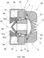
- Fig. 16A illustrates a fourth embodiment of a compression driver (B4) that comprises a first output duct (O1) and a second output duct (02).
- the magnetic unit (3) comprises an annular magnet (30) disposed between a yoke (4) and an upper pole plate (31), both of them having an annular shape,
- a shank (40) is axially disposed in the yoke, the magnet and the upper pole plate, in such a way to define a first air gap between shank (40) and upper pole plate (31), wherein a first voice coil (2) is disposed, and a second air gap between shank (40) and yoke (4), wherein a second voice coil (2a) is disposed.
- the shank (40) is fixed to the yoke by means of an L-shaped element (35) made of non-ferromagnetic material.
- a first dome-shaped membrane (1) is fixed to the first voice coil (2). In this way, a front chamber (91) is formed between the shank (40) and the first membrane (1).
- a first support (6) is disposed in front of the first membrane (1).
- the first support (6) has passages (62) that end in the first output duct (O1) suitable for being used to introduce the sound outside the vehicle compartment, using the first dome-shaped membrane (1).
- a second membrane (1a) with annular shape and V-shaped section is fixed to the second voice coil (2a).
- a second support (6a) is disposed in front of the second membrane (1).
- the second support (6a) has passages (62a) that end in the second output duct (02) suitable for being used to introduce sound inside the vehicle compartment, using the second annular membrane (1a).
- the second support (6a) has an axial seat (61a) with tapered shape that forms a rear chamber (90) between the shank (40) and the second support.
- the shank (40) has an axial duct (45) that puts the front chamber (91) in communication with the rear chamber (90).
- a casing (95) connects the second support (6a) to the magnetic unit in such a way to define a peripheral annular chamber (92) around the second support (6a).
- Fig. 16B illustrates an embodiment with two compression drivers (B2, B2') that are similar to Fig. 4A and are disposed in back to back configuration, in such a way that the first compression driver (B2) emits the sound in a first output duct (O1), and the second compression driver (B2') emits the sound in a second output duct (02) disposed at 180° with respect to the first output duct (O1).
- the enclosure (9) instead of being shaped like a dome, the enclosure (9) has a parallelepiped shape for easier mounting.
- the first compression driver (B2) can be larger than the second compression driver (B2').
- a second embodiment of the sound generating system (200) is illustrated, wherein the first wave-guide (C) directed towards the convex side of the membrane (1) is used to convey the sound reproduced by the compression driver (B3; B4; B2, B2') outside of the vehicle.
- the second wave-guide (D) is used to convey the sound inside the vehicle compartment.
- the two sounds reproduced by the two wave-guides (C, D) are push-pull, but insist in two space portions that are separated without interaction.
- the first wave-guide (C) that emits the sound outside is associated with the convex part of the membrane (1) of the compression driver (B3;B4; B2), in such a way that the coil voice (2) is protected against weather agents.
- the outlet (82) of the second wave-guide (D) is disposed behind the rear seats of the vehicle.
- the outlet (82) of the second wave-guide (D) is disposed above the rear seats of the vehicle.
Landscapes
- Physics & Mathematics (AREA)
- Engineering & Computer Science (AREA)
- Acoustics & Sound (AREA)
- Health & Medical Sciences (AREA)
- Otolaryngology (AREA)
- Multimedia (AREA)
- Signal Processing (AREA)
- Fittings On The Vehicle Exterior For Carrying Loads, And Devices For Holding Or Mounting Articles (AREA)
Claims (11)
- Klangerzeugungssystem (200) für ein Fahrzeug (A), umfassend:- einen elektroakustischen Wandler (B), der geeignet ist, einen Klang als Reaktion auf ein elektrisches Eingangssignal zu erzeugen,- einen digitalen Signalprozessor (DSP) (102), der elektrisch mit dem elektroakustischen Wandler (B) verbunden ist, um den elektroakustischen Wandler (B) so zu steuern, dass dieser einen Klang abgibt; wobei der (DSP) (102) so konfiguriert ist, dass der elektroakustische Wandler (B) einen Klang abgibt, der dem von den Abgasen eines Verbrennungsmotors erzeugten Klang ähnlich ist; und- einen akustischen Wellenleiter oder ein Horn (C), der/das mit dem elektroakustischen Wandler (B) gekoppelt ist, um den von dem elektroakustischen Wandler abgegebenen Klang zu leiten und zu konzentrieren,wobei der elektroakustische Wandler (B) in dem Fahrzeug (A) angeordnet ist und ein Teil des akustischen Wellenleiters (C) innerhalb des Fahrzeugs (A) liegt und ein anderer Teil des akustischen Wellenleiters außerhalb des Fahrzeugs liegt, wo der Klang abgegeben wird;wobei der elektroakustische Wandler (B) eine Klangerzeugungsmembran (1) umfasst unddas Klangerzeugungssystem (200) einen ersten akustischen Wellenleiter (C) umfasst, der mit dem elektroakustischen Wandler (B) vor der Membran gekoppelt ist und einen zweiten akustischen Wellenleiter (D), der mit dem elektroakustischen Wandler (B) hinter der Membran gekoppelt ist,der erste akustische Wellenleiter (C) eine Auslassmündung (82) außerhalb des Fahrzeugs aufweist, um den Klang außerhalb des Fahrzeugs abzugeben, und der zweite akustische Wellenleiter (D) eine Auslassmündung (82) innerhalb des Fahrzeugs aufweist, um den Klang innerhalb des Fahrzeugs abzugeben.
- Klangerzeugungssystem (200) nach Anspruch 1, wobei die Membran (1) kuppelartige oder konische Form aufweist, so dass eine konkave Seite und eine konvexe Seite definiert wird; der erste akustische Wellenleiter (C) der konvexen Seite der Membran zugewandt ist; und der zweite akustische Wellenleiter (D) der konkaven Seite der Membran zugewandt ist.
- Klangerzeugungssystem (200) nach Anspruch 2, wobei der elektroakustische Wandler (B) ein Kompressionstreiber (B3; B4; B2, B2') ist, der Folgendes umfasst:- eine Schwingspule (2), die mit der Membran (1) gekoppelt ist und in einem Luftspalt mit einem Magnetfeld angeordnet ist, das von einer Magneteinheit (3) erzeugt wird,- eine Zentriervorrichtung (5), die mit der Magneteinheit (3) und der Schwingspule (2) verbunden ist, um die Schwingspule (2) in dem Luftspalt zu zentrieren,- einen Träger (6), der auf der Magneteinheit angeordnet ist; wobei der Träger (6) eine konkave Oberfläche (61) aufweist, die der konvexen Oberfläche der Membran (1) zugewandt ist; wobei in der konkaven Oberfläche (61) des Trägers eine Vielzahl von Öffnungen vorhanden ist, die mit Durchgängen (62) in Verbindung stehen, die zu einer ersten Ausgangsleitung (O1) zur Klangabgabe führen; und- eine untere Polplatte (4) und einen Schaft (40), der in der Schwingspule (2) angeordnet ist.
- Klangerzeugungssystem (200) nach Anspruch 3, wobei der Schaft (40) des Kompressionstreibers (B3) eine konvexe Oberfläche (41) aufweist, die der konkaven Oberfläche der Membran (1) zugewandt ist; wobei auf der konvexen Oberfläche (41) des Schafts eine Vielzahl von Öffnungen vorhanden ist, die mit Durchgängen (42) in Verbindung stehen, die zu einer zweiten Ausgangsleitung (02) zur Klangabgabe führen.
- Klangerzeugungssystem (200) nach Anspruch 3, wobei der Schaft (40) des Kompressionstreibers (B4, B2) eine axiale Leitung (45) umfasst, die eine zwischen dem Schaft (40) und der Membran (1) angeordnete vordere Kammer (91) und eine zwischen dem Schaft (40) und einem zweiten Träger (6a) oder Gehäuse (9) angeordnete hintere Kammer (90) in Verbindung bringt.
- Klangerzeugungssystem (200) nach Anspruch 5, wobei der Kompressionstreiber (B4) Folgendes umfasst:- eine zweite Schwingspule (2a), die in einem zweiten Luftspalt zwischen dem Schaft (40) und der unteren Polplatte (4) angeordnet ist,- eine zweite Membran (1a) mit Ringform, die mit der zweiten Schwingspule (2a) verbunden ist, und- einen zweiten Träger (6a), der der zweiten Membran (1a) zugewandt ist und mit Durchgängen (62) versehen ist, die zu einer zweiten Ausgangsleitung (02) für die Klangabgabe führen.
- Klangerzeugungssystem (200) nach Anspruch 3, umfassend zwei Kompressionstreiber (B2, B2'), die in einer O-Anordnung so angeordnet sind, dass der erste Kompressionstreiber den Klang in einer ersten Ausgangsleitung (O1) abgibt und die zweite Ausgangsleitung (02) im Winkel von 180° in Bezug auf die erste Ausgangsleitung (O1) angeordnet ist.
- Klangerzeugungssystem (200) nach einem der vorstehenden Ansprüche, umfassend einen ersten und einen zweiten Phasenstecker (R), die zwischen dem elektroakustischen Wandler (B) und dem ersten Wellenleiter (C) bzw. zwischen dem elektroakustischen Wandler (B) und dem zweiten Wellenleiter (D) angeordnet sind.
- Klangerzeugungssystem (200) nach einem der vorstehenden Ansprüche, ferner umfassend einen Schalldämpfer (E), der in dem zweiten Wellenleiter (D) angeordnet ist.
- Klangerzeugungssystem (200) nach einem der vorstehenden Ansprüche, wobei der erste akustische Wellenleiter (C) eine Einlassnut (8) und einen Körper (81) aufweist, der eine konische Leitung (83) definiert, deren Abmessungen von der Einlassnut (8) zu einer Auslassmündung (82) hin zunehmen; wobei der erste akustische Wellenleiter (C) einen S-förmig gewundenen Weg oder einen gebogenen Weg von der Einlassnut (8) zu der Auslassmündung (82) erzeugt.
- Klangerzeugungssystem (200) nach einem der vorstehenden Ansprüche, wobei der DSP (101) mit einer elektronischen Steuereinheit (ECU) (103) des Fahrzeugs und/oder mit Sensoren (101) verbunden ist, die in dem Fahrzeug angeordnet sind, um Parameter des Fahrzeugs zu erfassen, die auf einen Klang hinweisen, der von den Abgasen eines Verbrennungsmotors erzeugt wird.
Applications Claiming Priority (2)
| Application Number | Priority Date | Filing Date | Title |
|---|---|---|---|
| IT201900008937 | 2019-06-13 | ||
| PCT/EP2020/066168 WO2020249660A1 (en) | 2019-06-13 | 2020-06-11 | High-performance sound generating system for vehicles |
Publications (2)
| Publication Number | Publication Date |
|---|---|
| EP3984019A1 EP3984019A1 (de) | 2022-04-20 |
| EP3984019B1 true EP3984019B1 (de) | 2024-08-21 |
Family
ID=68281826
Family Applications (1)
| Application Number | Title | Priority Date | Filing Date |
|---|---|---|---|
| EP20730669.7A Active EP3984019B1 (de) | 2019-06-13 | 2020-06-11 | Hochleistungsschallerzeugungssystem für fahrzeuge |
Country Status (3)
| Country | Link |
|---|---|
| EP (1) | EP3984019B1 (de) |
| MA (1) | MA56171A (de) |
| WO (1) | WO2020249660A1 (de) |
Families Citing this family (6)
| Publication number | Priority date | Publication date | Assignee | Title |
|---|---|---|---|---|
| GB2590656A (en) * | 2019-12-23 | 2021-07-07 | Gp Acoustics International Ltd | Loudspeakers |
| JP7600945B2 (ja) * | 2021-09-27 | 2024-12-17 | 豊田合成株式会社 | 車両用音出力装置及び車両用音伝搬装置 |
| WO2023086310A1 (en) * | 2021-11-09 | 2023-05-19 | Fca Us Llc | Active sound and vibration enhancement systems for battery electric vehicle |
| US20230144723A1 (en) | 2021-11-09 | 2023-05-11 | Fca Us Llc | Battery electric vehicle active sound and vibration enhancement systems |
| EP4221254A1 (de) | 2022-01-31 | 2023-08-02 | Harman International Industries, Incorporated | Lautsprecheranordnung |
| IT202200019326A1 (it) * | 2022-09-21 | 2024-03-21 | Ferrari Spa | Veicolo provvisto di un assale a trazione elettrica e di un sistema di trasmissione acustica per trasmettere suoni indicativi del funzionamento di tale assale |
Family Cites Families (10)
| Publication number | Priority date | Publication date | Assignee | Title |
|---|---|---|---|---|
| US2037187A (en) | 1933-03-28 | 1936-04-14 | Bell Telephone Labor Inc | Sound translating device |
| US6038326A (en) | 1998-01-28 | 2000-03-14 | Czerwinski; Eugene J. | Loudspeaker and horn with an additional transducer |
| JP2010228564A (ja) | 2009-03-26 | 2010-10-14 | Yamaha Corp | 自動車 |
| JP5591573B2 (ja) | 2009-03-30 | 2014-09-17 | 東京エレクトロン株式会社 | プラズマ処理装置及びプラズマ処理方法 |
| DE102013208098A1 (de) | 2013-05-03 | 2014-11-06 | Eberspächer Exhaust Technology GmbH & Co. KG | Straßenfahrzeug |
| US10555072B2 (en) | 2014-06-18 | 2020-02-04 | Harman International Industries, Incorporated | Aperture patterns and orientations for optimization of phasing plug performance in compression drivers |
| ITUB20159781A1 (it) | 2015-01-13 | 2017-06-30 | Ask Ind Spa | Sistema di arricchimento del suono del motore in un veicolo. |
| US10531194B2 (en) | 2015-01-28 | 2020-01-07 | Harman International Industries, Incorporated | Vehicle speaker arrangement |
| DE102017203184B4 (de) | 2017-02-28 | 2021-09-02 | Audi Ag | Klangerzeugungsvorrichtung zur Erzeugung von Abgasanlagensound mit mehreren Ausgangsöffnungen sowie ein zugehöriges Kraftfahrzeug |
| DE102017210688B4 (de) | 2017-06-26 | 2021-10-14 | Audi Ag | Schallerzeugungseinrichtung für ein Kraftfahrzeug |
-
2020
- 2020-06-11 EP EP20730669.7A patent/EP3984019B1/de active Active
- 2020-06-11 WO PCT/EP2020/066168 patent/WO2020249660A1/en not_active Ceased
- 2020-06-11 MA MA056171A patent/MA56171A/fr unknown
Also Published As
| Publication number | Publication date |
|---|---|
| EP3984019A1 (de) | 2022-04-20 |
| MA56171A (fr) | 2022-04-20 |
| WO2020249660A1 (en) | 2020-12-17 |
Similar Documents
| Publication | Publication Date | Title |
|---|---|---|
| EP3984019B1 (de) | Hochleistungsschallerzeugungssystem für fahrzeuge | |
| US5828759A (en) | System and method for reducing engine noise | |
| US6084971A (en) | Active noise attenuation system | |
| JP4264068B2 (ja) | 車両内における音響波誘導 | |
| CN106973339B (zh) | 用于扬声器的声透镜系统 | |
| CN108810721B (zh) | 机动车辆声音发生器系统 | |
| JPH08512410A (ja) | 能動的な消音器 | |
| JP2017122432A (ja) | 車両騒音を操作するために車両に搭載される音生成器 | |
| CN104141521A (zh) | 用于影响机动车辆排气噪声和/或进气噪声的抗噪系统的声发生器 | |
| US12395786B2 (en) | Loudspeaker | |
| US5255321A (en) | Acoustic transducer for automotive noise cancellation | |
| JP2008025472A (ja) | 騒音低減装置 | |
| JP7283715B2 (ja) | 空調機器用消音装置 | |
| CN119189870A (zh) | 一种车辆警告装置 | |
| JP4454362B2 (ja) | 能動型消音装置 | |
| EP1256110B1 (de) | Signalhorn | |
| US5022488A (en) | Transducer enclosure | |
| EP1249829B1 (de) | Niederfrequente aktive Geräuschdämpfung | |
| EP4227937B1 (de) | Akustisches fahrzeugwarnsystem | |
| EP1085198B1 (de) | Aktiv gesteuerter Einlasslärm mit Multipole-Einlassvorrichtung | |
| JP2014008902A (ja) | 車両存在通報装置 | |
| JPH02130099A (ja) | 消音装置 | |
| CN121888173A (zh) | 换能器组件 | |
| JPH02203699A (ja) | スピーカシステム | |
| CN121970371A (zh) | 扬声器组件和电动车辆 |
Legal Events
| Date | Code | Title | Description |
|---|---|---|---|
| STAA | Information on the status of an ep patent application or granted ep patent |
Free format text: STATUS: UNKNOWN |
|
| STAA | Information on the status of an ep patent application or granted ep patent |
Free format text: STATUS: THE INTERNATIONAL PUBLICATION HAS BEEN MADE |
|
| PUAI | Public reference made under article 153(3) epc to a published international application that has entered the european phase |
Free format text: ORIGINAL CODE: 0009012 |
|
| STAA | Information on the status of an ep patent application or granted ep patent |
Free format text: STATUS: REQUEST FOR EXAMINATION WAS MADE |
|
| 17P | Request for examination filed |
Effective date: 20211115 |
|
| AK | Designated contracting states |
Kind code of ref document: A1 Designated state(s): AL AT BE BG CH CY CZ DE DK EE ES FI FR GB GR HR HU IE IS IT LI LT LU LV MC MK MT NL NO PL PT RO RS SE SI SK SM TR |
|
| GRAP | Despatch of communication of intention to grant a patent |
Free format text: ORIGINAL CODE: EPIDOSNIGR1 |
|
| STAA | Information on the status of an ep patent application or granted ep patent |
Free format text: STATUS: GRANT OF PATENT IS INTENDED |
|
| INTG | Intention to grant announced |
Effective date: 20240522 |
|
| RIN1 | Information on inventor provided before grant (corrected) |
Inventor name: NILI, TIZIANO Inventor name: ARLETTI, MAURIZIO Inventor name: CINANNI, DARIO Inventor name: UGOLOTTI, EMANUELE Inventor name: MANINI, ALESSANDRO Inventor name: PRATI, STEFANO |
|
| GRAS | Grant fee paid |
Free format text: ORIGINAL CODE: EPIDOSNIGR3 |
|
| GRAA | (expected) grant |
Free format text: ORIGINAL CODE: 0009210 |
|
| STAA | Information on the status of an ep patent application or granted ep patent |
Free format text: STATUS: THE PATENT HAS BEEN GRANTED |
|
| AK | Designated contracting states |
Kind code of ref document: B1 Designated state(s): AL AT BE BG CH CY CZ DE DK EE ES FI FR GB GR HR HU IE IS IT LI LT LU LV MC MK MT NL NO PL PT RO RS SE SI SK SM TR |
|
| REG | Reference to a national code |
Ref country code: GB Ref legal event code: FG4D |
|
| REG | Reference to a national code |
Ref country code: CH Ref legal event code: EP |
|
| REG | Reference to a national code |
Ref country code: DE Ref legal event code: R096 Ref document number: 602020036199 Country of ref document: DE |
|
| REG | Reference to a national code |
Ref country code: IE Ref legal event code: FG4D |
|
| REG | Reference to a national code |
Ref country code: LT Ref legal event code: MG9D |
|
| P01 | Opt-out of the competence of the unified patent court (upc) registered |
Free format text: CASE NUMBER: APP_60144/2024 Effective date: 20241107 |
|
| REG | Reference to a national code |
Ref country code: NL Ref legal event code: MP Effective date: 20240821 |
|
| PG25 | Lapsed in a contracting state [announced via postgrant information from national office to epo] |
Ref country code: NO Free format text: LAPSE BECAUSE OF FAILURE TO SUBMIT A TRANSLATION OF THE DESCRIPTION OR TO PAY THE FEE WITHIN THE PRESCRIBED TIME-LIMIT Effective date: 20241121 |
|
| REG | Reference to a national code |
Ref country code: AT Ref legal event code: MK05 Ref document number: 1716307 Country of ref document: AT Kind code of ref document: T Effective date: 20240821 |
|
| PG25 | Lapsed in a contracting state [announced via postgrant information from national office to epo] |
Ref country code: NL Free format text: LAPSE BECAUSE OF FAILURE TO SUBMIT A TRANSLATION OF THE DESCRIPTION OR TO PAY THE FEE WITHIN THE PRESCRIBED TIME-LIMIT Effective date: 20240821 Ref country code: FI Free format text: LAPSE BECAUSE OF FAILURE TO SUBMIT A TRANSLATION OF THE DESCRIPTION OR TO PAY THE FEE WITHIN THE PRESCRIBED TIME-LIMIT Effective date: 20240821 Ref country code: PL Free format text: LAPSE BECAUSE OF FAILURE TO SUBMIT A TRANSLATION OF THE DESCRIPTION OR TO PAY THE FEE WITHIN THE PRESCRIBED TIME-LIMIT Effective date: 20240821 Ref country code: GR Free format text: LAPSE BECAUSE OF FAILURE TO SUBMIT A TRANSLATION OF THE DESCRIPTION OR TO PAY THE FEE WITHIN THE PRESCRIBED TIME-LIMIT Effective date: 20241122 Ref country code: PT Free format text: LAPSE BECAUSE OF FAILURE TO SUBMIT A TRANSLATION OF THE DESCRIPTION OR TO PAY THE FEE WITHIN THE PRESCRIBED TIME-LIMIT Effective date: 20241223 |
|
| PG25 | Lapsed in a contracting state [announced via postgrant information from national office to epo] |
Ref country code: BG Free format text: LAPSE BECAUSE OF FAILURE TO SUBMIT A TRANSLATION OF THE DESCRIPTION OR TO PAY THE FEE WITHIN THE PRESCRIBED TIME-LIMIT Effective date: 20240821 |
|
| PG25 | Lapsed in a contracting state [announced via postgrant information from national office to epo] |
Ref country code: LV Free format text: LAPSE BECAUSE OF FAILURE TO SUBMIT A TRANSLATION OF THE DESCRIPTION OR TO PAY THE FEE WITHIN THE PRESCRIBED TIME-LIMIT Effective date: 20240821 |
|
| PG25 | Lapsed in a contracting state [announced via postgrant information from national office to epo] |
Ref country code: AT Free format text: LAPSE BECAUSE OF FAILURE TO SUBMIT A TRANSLATION OF THE DESCRIPTION OR TO PAY THE FEE WITHIN THE PRESCRIBED TIME-LIMIT Effective date: 20240821 Ref country code: IS Free format text: LAPSE BECAUSE OF FAILURE TO SUBMIT A TRANSLATION OF THE DESCRIPTION OR TO PAY THE FEE WITHIN THE PRESCRIBED TIME-LIMIT Effective date: 20241221 |
|
| PG25 | Lapsed in a contracting state [announced via postgrant information from national office to epo] |
Ref country code: HR Free format text: LAPSE BECAUSE OF FAILURE TO SUBMIT A TRANSLATION OF THE DESCRIPTION OR TO PAY THE FEE WITHIN THE PRESCRIBED TIME-LIMIT Effective date: 20240821 |
|
| PG25 | Lapsed in a contracting state [announced via postgrant information from national office to epo] |
Ref country code: RS Free format text: LAPSE BECAUSE OF FAILURE TO SUBMIT A TRANSLATION OF THE DESCRIPTION OR TO PAY THE FEE WITHIN THE PRESCRIBED TIME-LIMIT Effective date: 20241121 Ref country code: ES Free format text: LAPSE BECAUSE OF FAILURE TO SUBMIT A TRANSLATION OF THE DESCRIPTION OR TO PAY THE FEE WITHIN THE PRESCRIBED TIME-LIMIT Effective date: 20240821 |
|
| PG25 | Lapsed in a contracting state [announced via postgrant information from national office to epo] |
Ref country code: RS Free format text: LAPSE BECAUSE OF FAILURE TO SUBMIT A TRANSLATION OF THE DESCRIPTION OR TO PAY THE FEE WITHIN THE PRESCRIBED TIME-LIMIT Effective date: 20241121 Ref country code: PT Free format text: LAPSE BECAUSE OF FAILURE TO SUBMIT A TRANSLATION OF THE DESCRIPTION OR TO PAY THE FEE WITHIN THE PRESCRIBED TIME-LIMIT Effective date: 20241223 Ref country code: PL Free format text: LAPSE BECAUSE OF FAILURE TO SUBMIT A TRANSLATION OF THE DESCRIPTION OR TO PAY THE FEE WITHIN THE PRESCRIBED TIME-LIMIT Effective date: 20240821 Ref country code: NO Free format text: LAPSE BECAUSE OF FAILURE TO SUBMIT A TRANSLATION OF THE DESCRIPTION OR TO PAY THE FEE WITHIN THE PRESCRIBED TIME-LIMIT Effective date: 20241121 Ref country code: NL Free format text: LAPSE BECAUSE OF FAILURE TO SUBMIT A TRANSLATION OF THE DESCRIPTION OR TO PAY THE FEE WITHIN THE PRESCRIBED TIME-LIMIT Effective date: 20240821 Ref country code: LV Free format text: LAPSE BECAUSE OF FAILURE TO SUBMIT A TRANSLATION OF THE DESCRIPTION OR TO PAY THE FEE WITHIN THE PRESCRIBED TIME-LIMIT Effective date: 20240821 Ref country code: IS Free format text: LAPSE BECAUSE OF FAILURE TO SUBMIT A TRANSLATION OF THE DESCRIPTION OR TO PAY THE FEE WITHIN THE PRESCRIBED TIME-LIMIT Effective date: 20241221 Ref country code: HR Free format text: LAPSE BECAUSE OF FAILURE TO SUBMIT A TRANSLATION OF THE DESCRIPTION OR TO PAY THE FEE WITHIN THE PRESCRIBED TIME-LIMIT Effective date: 20240821 Ref country code: GR Free format text: LAPSE BECAUSE OF FAILURE TO SUBMIT A TRANSLATION OF THE DESCRIPTION OR TO PAY THE FEE WITHIN THE PRESCRIBED TIME-LIMIT Effective date: 20241122 Ref country code: FI Free format text: LAPSE BECAUSE OF FAILURE TO SUBMIT A TRANSLATION OF THE DESCRIPTION OR TO PAY THE FEE WITHIN THE PRESCRIBED TIME-LIMIT Effective date: 20240821 Ref country code: ES Free format text: LAPSE BECAUSE OF FAILURE TO SUBMIT A TRANSLATION OF THE DESCRIPTION OR TO PAY THE FEE WITHIN THE PRESCRIBED TIME-LIMIT Effective date: 20240821 Ref country code: BG Free format text: LAPSE BECAUSE OF FAILURE TO SUBMIT A TRANSLATION OF THE DESCRIPTION OR TO PAY THE FEE WITHIN THE PRESCRIBED TIME-LIMIT Effective date: 20240821 Ref country code: AT Free format text: LAPSE BECAUSE OF FAILURE TO SUBMIT A TRANSLATION OF THE DESCRIPTION OR TO PAY THE FEE WITHIN THE PRESCRIBED TIME-LIMIT Effective date: 20240821 |
|
| PG25 | Lapsed in a contracting state [announced via postgrant information from national office to epo] |
Ref country code: SM Free format text: LAPSE BECAUSE OF FAILURE TO SUBMIT A TRANSLATION OF THE DESCRIPTION OR TO PAY THE FEE WITHIN THE PRESCRIBED TIME-LIMIT Effective date: 20240821 Ref country code: DK Free format text: LAPSE BECAUSE OF FAILURE TO SUBMIT A TRANSLATION OF THE DESCRIPTION OR TO PAY THE FEE WITHIN THE PRESCRIBED TIME-LIMIT Effective date: 20240821 Ref country code: RO Free format text: LAPSE BECAUSE OF FAILURE TO SUBMIT A TRANSLATION OF THE DESCRIPTION OR TO PAY THE FEE WITHIN THE PRESCRIBED TIME-LIMIT Effective date: 20240821 |
|
| PG25 | Lapsed in a contracting state [announced via postgrant information from national office to epo] |
Ref country code: EE Free format text: LAPSE BECAUSE OF FAILURE TO SUBMIT A TRANSLATION OF THE DESCRIPTION OR TO PAY THE FEE WITHIN THE PRESCRIBED TIME-LIMIT Effective date: 20240821 |
|
| PG25 | Lapsed in a contracting state [announced via postgrant information from national office to epo] |
Ref country code: CZ Free format text: LAPSE BECAUSE OF FAILURE TO SUBMIT A TRANSLATION OF THE DESCRIPTION OR TO PAY THE FEE WITHIN THE PRESCRIBED TIME-LIMIT Effective date: 20240821 |
|
| PG25 | Lapsed in a contracting state [announced via postgrant information from national office to epo] |
Ref country code: SK Free format text: LAPSE BECAUSE OF FAILURE TO SUBMIT A TRANSLATION OF THE DESCRIPTION OR TO PAY THE FEE WITHIN THE PRESCRIBED TIME-LIMIT Effective date: 20240821 |
|
| REG | Reference to a national code |
Ref country code: DE Ref legal event code: R097 Ref document number: 602020036199 Country of ref document: DE |
|
| VS25 | Lapsed in a validation state [announced via postgrant information from nat. office to epo] |
Ref country code: MD Free format text: LAPSE BECAUSE OF FAILURE TO SUBMIT A TRANSLATION OF THE DESCRIPTION OR TO PAY THE FEE WITHIN THE PRESCRIBED TIME-LIMIT Effective date: 20240821 |
|
| PLBE | No opposition filed within time limit |
Free format text: ORIGINAL CODE: 0009261 |
|
| STAA | Information on the status of an ep patent application or granted ep patent |
Free format text: STATUS: NO OPPOSITION FILED WITHIN TIME LIMIT |
|
| PGFP | Annual fee paid to national office [announced via postgrant information from national office to epo] |
Ref country code: DE Payment date: 20250626 Year of fee payment: 6 |
|
| PGFP | Annual fee paid to national office [announced via postgrant information from national office to epo] |
Ref country code: GB Payment date: 20250618 Year of fee payment: 6 |
|
| PGFP | Annual fee paid to national office [announced via postgrant information from national office to epo] |
Ref country code: IT Payment date: 20250520 Year of fee payment: 6 |
|
| PGFP | Annual fee paid to national office [announced via postgrant information from national office to epo] |
Ref country code: FR Payment date: 20250624 Year of fee payment: 6 |
|
| 26N | No opposition filed |
Effective date: 20250522 |
|
| PG25 | Lapsed in a contracting state [announced via postgrant information from national office to epo] |
Ref country code: SE Free format text: LAPSE BECAUSE OF FAILURE TO SUBMIT A TRANSLATION OF THE DESCRIPTION OR TO PAY THE FEE WITHIN THE PRESCRIBED TIME-LIMIT Effective date: 20240821 |
|
| REG | Reference to a national code |
Ref country code: CH Ref legal event code: H13 Free format text: ST27 STATUS EVENT CODE: U-0-0-H10-H13 (AS PROVIDED BY THE NATIONAL OFFICE) Effective date: 20260127 |
|
| PG25 | Lapsed in a contracting state [announced via postgrant information from national office to epo] |
Ref country code: MC Free format text: LAPSE BECAUSE OF FAILURE TO SUBMIT A TRANSLATION OF THE DESCRIPTION OR TO PAY THE FEE WITHIN THE PRESCRIBED TIME-LIMIT Effective date: 20240821 |
|
| PG25 | Lapsed in a contracting state [announced via postgrant information from national office to epo] |
Ref country code: LU Free format text: LAPSE BECAUSE OF NON-PAYMENT OF DUE FEES Effective date: 20250611 |
|
| REG | Reference to a national code |
Ref country code: BE Ref legal event code: MM Effective date: 20250630 |
|
| PG25 | Lapsed in a contracting state [announced via postgrant information from national office to epo] |
Ref country code: IE Free format text: LAPSE BECAUSE OF NON-PAYMENT OF DUE FEES Effective date: 20250611 |
|
| PG25 | Lapsed in a contracting state [announced via postgrant information from national office to epo] |
Ref country code: BE Free format text: LAPSE BECAUSE OF NON-PAYMENT OF DUE FEES Effective date: 20250630 |
|
| VS25 | Lapsed in a validation state [announced via postgrant information from nat. office to epo] |
Ref country code: MA Free format text: LAPSE BECAUSE OF FAILURE TO SUBMIT A TRANSLATION OF THE DESCRIPTION OR TO PAY THE FEE WITHIN THE PRESCRIBED TIME-LIMIT; INVALID AB INITIO Effective date: 20200611 |
|
| PG25 | Lapsed in a contracting state [announced via postgrant information from national office to epo] |
Ref country code: CH Free format text: LAPSE BECAUSE OF NON-PAYMENT OF DUE FEES Effective date: 20250630 |