EP3981523A1 - Bending system - Google Patents
Bending system Download PDFInfo
- Publication number
- EP3981523A1 EP3981523A1 EP20818856.5A EP20818856A EP3981523A1 EP 3981523 A1 EP3981523 A1 EP 3981523A1 EP 20818856 A EP20818856 A EP 20818856A EP 3981523 A1 EP3981523 A1 EP 3981523A1
- Authority
- EP
- European Patent Office
- Prior art keywords
- tool
- right direction
- moving body
- die
- tools
- Prior art date
- Legal status (The legal status is an assumption and is not a legal conclusion. Google has not performed a legal analysis and makes no representation as to the accuracy of the status listed.)
- Granted
Links
Images







Classifications
-
- B—PERFORMING OPERATIONS; TRANSPORTING
- B21—MECHANICAL METAL-WORKING WITHOUT ESSENTIALLY REMOVING MATERIAL; PUNCHING METAL
- B21D—WORKING OR PROCESSING OF SHEET METAL OR METAL TUBES, RODS OR PROFILES WITHOUT ESSENTIALLY REMOVING MATERIAL; PUNCHING METAL
- B21D5/00—Bending sheet metal along straight lines, e.g. to form simple curves
- B21D5/02—Bending sheet metal along straight lines, e.g. to form simple curves on press brakes without making use of clamping means
-
- B—PERFORMING OPERATIONS; TRANSPORTING
- B21—MECHANICAL METAL-WORKING WITHOUT ESSENTIALLY REMOVING MATERIAL; PUNCHING METAL
- B21D—WORKING OR PROCESSING OF SHEET METAL OR METAL TUBES, RODS OR PROFILES WITHOUT ESSENTIALLY REMOVING MATERIAL; PUNCHING METAL
- B21D5/00—Bending sheet metal along straight lines, e.g. to form simple curves
- B21D5/004—Bending sheet metal along straight lines, e.g. to form simple curves with program control
-
- B—PERFORMING OPERATIONS; TRANSPORTING
- B21—MECHANICAL METAL-WORKING WITHOUT ESSENTIALLY REMOVING MATERIAL; PUNCHING METAL
- B21C—MANUFACTURE OF METAL SHEETS, WIRE, RODS, TUBES, PROFILES OR LIKE SEMI-MANUFACTURED PRODUCTS OTHERWISE THAN BY ROLLING; AUXILIARY OPERATIONS USED IN CONNECTION WITH METAL-WORKING WITHOUT ESSENTIALLY REMOVING MATERIAL
- B21C51/00—Measuring, gauging, indicating, counting, or marking devices specially adapted for use in the production or manipulation of material in accordance with subclasses B21B - B21F
-
- B—PERFORMING OPERATIONS; TRANSPORTING
- B21—MECHANICAL METAL-WORKING WITHOUT ESSENTIALLY REMOVING MATERIAL; PUNCHING METAL
- B21D—WORKING OR PROCESSING OF SHEET METAL OR METAL TUBES, RODS OR PROFILES WITHOUT ESSENTIALLY REMOVING MATERIAL; PUNCHING METAL
- B21D37/00—Tools as parts of machines covered by this subclass
- B21D37/04—Movable or exchangeable mountings for tools
-
- B—PERFORMING OPERATIONS; TRANSPORTING
- B21—MECHANICAL METAL-WORKING WITHOUT ESSENTIALLY REMOVING MATERIAL; PUNCHING METAL
- B21D—WORKING OR PROCESSING OF SHEET METAL OR METAL TUBES, RODS OR PROFILES WITHOUT ESSENTIALLY REMOVING MATERIAL; PUNCHING METAL
- B21D37/00—Tools as parts of machines covered by this subclass
- B21D37/14—Particular arrangements for handling and holding in place complete dies
- B21D37/145—Die storage magazines
-
- B—PERFORMING OPERATIONS; TRANSPORTING
- B21—MECHANICAL METAL-WORKING WITHOUT ESSENTIALLY REMOVING MATERIAL; PUNCHING METAL
- B21D—WORKING OR PROCESSING OF SHEET METAL OR METAL TUBES, RODS OR PROFILES WITHOUT ESSENTIALLY REMOVING MATERIAL; PUNCHING METAL
- B21D5/00—Bending sheet metal along straight lines, e.g. to form simple curves
- B21D5/02—Bending sheet metal along straight lines, e.g. to form simple curves on press brakes without making use of clamping means
- B21D5/0209—Tools therefor
- B21D5/0236—Tool clamping
-
- B—PERFORMING OPERATIONS; TRANSPORTING
- B21—MECHANICAL METAL-WORKING WITHOUT ESSENTIALLY REMOVING MATERIAL; PUNCHING METAL
- B21D—WORKING OR PROCESSING OF SHEET METAL OR METAL TUBES, RODS OR PROFILES WITHOUT ESSENTIALLY REMOVING MATERIAL; PUNCHING METAL
- B21D5/00—Bending sheet metal along straight lines, e.g. to form simple curves
- B21D5/02—Bending sheet metal along straight lines, e.g. to form simple curves on press brakes without making use of clamping means
- B21D5/0209—Tools therefor
- B21D5/0254—Tool exchanging
-
- Y—GENERAL TAGGING OF NEW TECHNOLOGICAL DEVELOPMENTS; GENERAL TAGGING OF CROSS-SECTIONAL TECHNOLOGIES SPANNING OVER SEVERAL SECTIONS OF THE IPC; TECHNICAL SUBJECTS COVERED BY FORMER USPC CROSS-REFERENCE ART COLLECTIONS [XRACs] AND DIGESTS
- Y10—TECHNICAL SUBJECTS COVERED BY FORMER USPC
- Y10T—TECHNICAL SUBJECTS COVERED BY FORMER US CLASSIFICATION
- Y10T483/00—Tool changing
- Y10T483/13—Tool changing with control means energized in response to activator stimulated by condition sensor
- Y10T483/136—Responsive to tool
-
- Y—GENERAL TAGGING OF NEW TECHNOLOGICAL DEVELOPMENTS; GENERAL TAGGING OF CROSS-SECTIONAL TECHNOLOGIES SPANNING OVER SEVERAL SECTIONS OF THE IPC; TECHNICAL SUBJECTS COVERED BY FORMER USPC CROSS-REFERENCE ART COLLECTIONS [XRACs] AND DIGESTS
- Y10—TECHNICAL SUBJECTS COVERED BY FORMER USPC
- Y10T—TECHNICAL SUBJECTS COVERED BY FORMER US CLASSIFICATION
- Y10T483/00—Tool changing
- Y10T483/17—Tool changing including machine tool or component
- Y10T483/1729—Reciprocating tool machine tool [e.g., broaching machine, shaping machine, etc.]
- Y10T483/1731—Reciprocating tool machine tool [e.g., broaching machine, shaping machine, etc.] including matrix
Definitions
- the present disclosure relates to a bending system for performing bending for a plate-shaped workpiece (a sheet metal).
- a bending system includes a press brake to perform bending for a workpiece, and the press brake includes upper and lower tables and tool holders provided on the respective tables and configured to retain tools. Further, the bending system includes a tool rack arranged on the side of the press brake and configured to store a plurality of tools. The tool rack has a plurality of stockers for retaining tools in which selected arbitrary stockers are configured such that the stockers can be positioned at exchange positions for performing tool exchange. Furthermore, the bending system includes tool exchange units for transporting tools between the tool holders and stockers positioned at the exchange positions, and each tool exchange unit has a tool retention member that is engageable with and disengageable from an engagement hole of a tool (see Patent Literature 1).
- Patent Literatures 2 to 4 exist in addition to the technique of Patent Literature 1.
- a conventional bending system does not recognize actual positions of tools in a left-right direction on tool holders. Therefore, the conventional bending system has the following problem.
- a tool is fitted to a position deviated from a regular arrangement position on a tool holder corresponding to tool layout information, and engagement or disengagement of a tool retention member with an engagement hole of a tool (a retention operation) fails, an alarm occurs, and an operation related to tool transportation by a tool exchange unit stops.
- a clamp plate or a clamper of a tool holder is accidentally released after tools are fitted to the tool holder, there is a possibility that the tools slightly move and are displaced from regular arrangement positions on the tool holder, and, therefore, it is not possible to perform the operation related to tool transportation by a tool exchange unit.
- the operation related to tool transportation is assumed to include an operation of exchanging tools fitted to a tool holder with tools fitted to a stocker, an operation of retaining a tool by a tool retention member and an operation of laying out tools on a tool holder or a stocker.
- an object of the present disclosure is to provide a bending system capable of accurately recognizing actual positions of tools in a left-right direction on a tool holder or on a stocker.
- a bending system includes: a moving body provided on a back side or a front side of a table of a press brake so as to be movable in a left-right direction; a moving actuator configured to cause the moving body to move in the left-right direction relative to the table; and a position detector configured to detect a position of the moving body in the left-right direction.
- the bending system includes: a hole detector provided on the moving body and configured to detect an engagement hole for causing a tool retention member of a tool exchange unit to be engaged and disengaged, the engagement hole being a part of a tool fitted to a tool holder provided on the table; and a hole position acquisition unit configured to acquire a position of the engagement hole of the tool in the left-right direction, based on the position of the moving body in the left-right direction at the time of the engagement hole of the tool being detected.
- the bending system according to the first aspect may further include an information reader provided on the moving body and configured to read, from a storage medium provided to the tool, tool information including a width dimension of the tool in the left-right direction and a relative position of the engagement hole in the tool.
- the moving body is moved in the left-right direction relative to the table by driving of the moving actuator while the position of the moving body in the left-right direction is being detected by the position detector. Further, during the movement of the moving body, the engagement hole of the tool is detected by the tool detector. Then, the hole position acquisition unit acquires the position of the engagement hole of the tool in the left-right direction, based on the position of the moving body in the left-right direction at the time of the engagement hole of the tool being detected. Thereby, the bending system can recognize an actual position of the engagement hole of the tool in the left-right direction on the tool holder.
- a bending system further includes: a moving body provided on a back side or a front side of a table of a press brake so as to be movable in a left-right direction; a moving actuator configured to cause the moving body to move in the left-right direction relative to the table; and a position detector configured to detect a position of the moving body in the left-right direction.
- the bending system includes: an end face detector provided on the moving body and configured to detect an end face of a tool fitted to a tool holder provided on the table; and an information reader provided on the moving body and configured to read, from a storage medium provided to the tool, tool information including a width dimension of the tool in the left-right direction and a relative position of an engagement hole in the tool, the engagement hole being a part of the tool and being for causing a tool retention member of a tool exchange unit to be engaged and disengaged.
- the bending system further includes: a hole position acquisition unit configured to acquire a position of the engagement hole of the tool in the left-right direction, based on the position of the moving body in the left-right direction at the time of the end face of the tool being detected, and the read tool information about the tool.
- the moving body is moved in the left-right direction by driving of the moving actuator while the position of the moving body in the left-right direction is being detected by the position detector.
- the end face of the tool is detected by the tool detector, and the tool information about the tool is read by the information reader.
- the hole position acquisition unit acquires the position of the engagement hole of the tool in the left-right direction, based on the position of the moving body in the left-right direction at the time of the end face of the tool being detected, and the read tool information about the tool.
- the bending system can recognize an actual position of the engagement hole of the tool in the left-right direction on the tool holder.
- a bending system includes: a moving body provided on a back side or a front side of a table of a press brake so as to be movable in a left-right direction; a moving actuator configured to cause the moving body to move in the left-right direction relative to the table; and a position detector configured to detect a position of the moving body in the left-right direction.
- the bending system according to the third aspect further includes: an end face detector provided on the moving body and configured to detect an end face of a tool fitted to a tool holder provided on the table; and an information reader provided on the moving body and configured to read, from a storage medium provided to the tool, tool information including a width dimension of the tool in the left-right direction.
- the bending system further includes a tool position acquisition unit configured to acquire a position of the tool in the left-right direction (a position of the end face of the tool in the left-right direction or a position of the center of the tool in the left-right direction), based on the position of the moving body in the left-right direction at the time of the end face of the tool being detected, and the read tool information about the tool.
- a tool position acquisition unit configured to acquire a position of the tool in the left-right direction (a position of the end face of the tool in the left-right direction or a position of the center of the tool in the left-right direction), based on the position of the moving body in the left-right direction at the time of the end face of the tool being detected, and the read tool information about the tool.
- the bending system according to the third aspect may further include an information reader provided on the moving body and configured to read, from a storage medium provided to the tool, tool information including a width dimension of the tool in the left-right direction.
- the moving body is moved in the left-right direction by driving of the moving actuator while the position of the moving body in the left-right direction is being detected by the position detector.
- the engagement hole of the tool is detected by the hole detector, and the tool information about the tool is read by the information reader.
- the tool position acquisition unit acquires the position of the tool in the left-right direction, based on the position of the moving body in the left-right direction at the time of the engagement hole of the tool being detected, and the read tool information about the tool.
- the bending system can recognize an actual position of the tool in the right direction on the tool holder.
- a left-right direction is one of horizontal directions and is synonymous with a lateral direction of a press brake, a tool rack, a tool holder or a tool.
- a front-back direction refers to a horizontal direction orthogonal to the left-right direction and is synonymous with a depth direction of the press brake or the tool rack.
- Read tool information about a tool is assumed to include reading identification information about a tool corresponding to tool information about the tool.
- "FF", “FR”, “L”, “R”, “U” and “D” refer to a front direction, a back direction, a left direction, a right direction, an up direction and a down direction, respectively.
- a bending system 10 is a system for performing bending for a plate-shaped workpiece (a sheet metal) W using punch tools 12 as automatically exchangeable upper tools and die tools 14 as lower tools. Further, the bending system 10 includes a press brake 16 to perform bending for the workpiece W in cooperation with the punch tools 12 and the die tools 14. First, a configuration of the press brake 16 will be specifically explained.
- the press brake 16 includes a main frame 18, and the main frame 18 has a pair of side plates 20 separated in the left-right direction and facing each other, and a plurality of coupling members 22 to couple the pair of side plates 20. Further, at a lower part of the main frame 18, a lower table 24 extending in the left-right direction is provided. At an upper part of the main frame 18, an upper table 26 extending in the left-right direction is provided being movable in a vertical direction. At an upper part of each side plate 20, a hydraulic cylinder 28 is provided as a vertically moving actuator to cause the upper table 26 to move in the vertical direction relative to the main frame 18.
- the lower table 24 may be configured to be movable in the vertical direction instead of configuring the upper table 26 to be movable in the vertical direction.
- servo motors (not shown) may be used instead of the hydraulic cylinders 28.
- a lower tool holder 30 to removably retain die tools 14 is provided, and the lower tool holder 30 extends in the left-right direction.
- a holder groove 30g into which shanks (bases) 14s of the die tools 14 are to be inserted is formed along the left-right direction, the holder groove 30g being in a publicly known configuration as shown in Patent Literatures 2 and 3.
- the lower tool holder 30 has a hydraulic clamper 32 to fix the die tools 14 to the lower table 24.
- each die tool 14 in the center of each die tool 14 in the left-right direction (the lateral direction), an engagement hole 14h as a part of the die tool 14 is penetratingly formed.
- identification marks 14m as storage media storing identification information about the die tool 14 are provided by engraving, and each identification mark 14m is configured with a two-dimensional code.
- the identification information about the die tool 14 corresponds to tool information about the die tool 14, and the tool information about the die tool 14 includes a type, shape, width dimension in the left-right direction and height dimension of the die tool 14, a relative position of the center of the engagement hole 14h in the die tool 14 and the like.
- the width dimension of the die tool 14 in the left-right direction is assumed to include a dimension from an end face 14e of the die tool 14 to the center of the die tool 14 in the left-right direction.
- the relative position of the center of the engagement hole 14h in the die tool 14 is assumed to include a dimension from the end face 14e of the die tool 14 to the center of the engagement hole 14h in the left-right direction and an amount of deviation of the center of the engagement hole 14h relative to the center of the die tool 14.
- an upper tool holder 34 to removably retain the punch tools 12 is provided on the lower side of the upper table 26, and the upper tool holder 34 extends in the left-right direction.
- a holder groove 34g into which shanks (bases) 12s of punch tools 12 are to be inserted is formed along the left-right direction, the holder groove 34g being in a publicly known configuration as shown in Patent Literatures 2 and 3.
- the upper tool holder 34 has a hydraulic clamp plate 36 to fix the punch tools 12 to the upper table 26.
- an engagement hole 12h as a part of the punch tool 12 is penetratingly formed.
- identification marks 12m as storage media storing identification information about the punch tool 12 are provided by engraving, and each identification mark 12m is configured with a two-dimensional code.
- the identification information about the punch tool 12 corresponds to tool information about the punch tool 12, and the tool information about the punch tool 12 includes a type, shape, width dimension in the left-right direction and height dimension of the punch tool 12, a relative position of the center of the engagement hole 12h in the punch tool 12 and the like.
- the width dimension of the punch tool 12 in the left-right direction is assumed to include a dimension from an end face 12e of the punch tool 12 to the center in the left-right direction.
- the relative position of the center of the engagement hole 12h in the punch tool 12 is assumed to include a dimension from the end face 12e of the punch tool 12 to the center of the engagement hole 12h in the left-right direction and an amount of deviation of the center of the engagement hole 12h relative to the center of the punch tool 12.
- a lower joint block 38 extending in the left-right direction is provided on one side (the right side) of the lower tool holder 30 in the left-right direction.
- a joint groove (not shown) into which the shank 14s of a die tool 14 is to be inserted is formed along the left-right direction.
- the joint groove of the lower joint block 38 is connected to the holder groove 30g (see Figure 3 ) of the lower tool holder 30.
- an upper joint block 40 extending in the left-right direction is provided.
- a joint groove (not shown) into which the shank 12s of a punch tool 12 are to be inserted is formed along the left-right direction.
- the joint groove 40g of the upper joint block 40 is connected to the holder groove 34g (see Figure 3 ) of the upper tool holder 34.
- the bending system 10 includes a tool rack 42 arranged on the side (the right side) of the press brake in the left-right direction and storing a plurality of die tools 14 and a plurality of punch tools 12.
- the tool rack 42 is, for example, in a publicly known configuration as shown in Patent Literatures 1 and 4. The configuration of the tool rack 42 will be simply explained.
- the tool rack 42 has a plurality of lower stockers 44 for retaining one or more die tools 14, and the plurality of lower stockers 44 are arranged in the front-back direction.
- Each lower stocker 44 extends in the left-right direction, and, on each lower stocker 44, a stocker groove 44g into which the shanks 14s of die tools 14 are to be inserted is formed along the left-right direction.
- a configuration is made so that a selected arbitrary lower stocker 44 is movable in the front-back direction by such a lower stocker movement mechanism (not shown) as shown in Patent Literature 1.
- the plurality of lower stockers 44 are configured to be synchronously movable in the front-back direction by such a lower stocker movement mechanism (not shown) as shown in Patent Literature 4.
- a configuration is made so that the selected arbitrary lower stocker 44 is positioned at a lower tool exchange position contiguous to the lower joint block 38 in the left-right direction, by its movement in the front-back direction.
- the stocker groove 44g of the lower stocker 44 is connected to the joint groove of the lower joint block 38.
- the tool rack 42 has a plurality of upper stockers 46 for retaining one or more punch tools 12, and the plurality of upper stockers 46 are arranged along the front-back direction.
- Each upper stocker 46 extends in the left-right direction, and, on each upper stocker 46, a stocker groove 46g into which the shanks 12s of punch tools 12 are to be inserted is formed along the left-right direction.
- a configuration is made so that a selected arbitrary upper stocker 46 is movable in the front-back direction by such an upper stocker movement mechanism (not shown) as shown in Patent Literature 1.
- the plurality of upper stockers 46 are configured to be synchronously movable in the front-back direction by such an upper stocker movement mechanism (not shown) as shown in Patent Literature 4.
- a configuration is made so that the selected arbitrary upper stocker 46 is positioned at an upper tool exchange position contiguous to the upper joint block 40 in the left-right direction, by its movement in the front-back direction.
- the stocker groove 46g of the upper stocker 46 is connected to the joint groove of the upper joint block 40.
- a lower guide 48 extending in the left-right direction is provided on the back side (the rear side) of the lower tool holder 30, and the lower guide 48 projects to the right of the lower joint block 38.
- a pair of lower tool exchange units 50 as lower moving bodies are provided being movable in the left-right direction via the lower guide 48.
- the lower tool exchange units 50 transport die tools 14 between the lower tool holder 30 and a lower stocker 44 positioned at the lower tool exchange position.
- Each lower tool exchange unit 50 moves in the left-right direction relative to the lower table 24 by driving of a servo motor 52 as a left-right moving actuator provided at an appropriate position on the lower tool exchange unit 50.
- the servo motor 52 has an encoder 54 as a position detector to detect a position of the lower tool exchange unit 50 in the left-right direction.
- Each lower tool exchange unit 50 is in a publicly known configuration as shown in Patent Literatures 2 and 3, and has a lower unit body 56 provided on the lower guide 48 being movable in the left-right direction and a lower support member 58 provided on the lower unit body 56 being movable in the front-back direction and in the vertical direction.
- the lower support member 58 moves in the front-back direction relative to the lower unit body 56 by driving of an air cylinder 60 as a front-back moving actuator provided at an appropriate position on the lower unit body 56.
- the lower support member 58 moves in the vertical direction relative to the lower unit body 56 by driving of an air cylinder 62 as a vertically moving actuator provided at an appropriate position on the lower unit body 56.
- Each lower tool exchange unit 50 has a lower tool retention member (a lower hook member) 64 provided on the lower support member 58 being movable in the front-back direction, and the lower tool retention member 64 is engageable with and disengageable from the engagement hole 14h of a die tool 14.
- the lower tool retention member 64 moves in the front-back direction relative to the lower support member 58 by driving of an air cylinder 66 as another front-back moving actuator provided at an appropriate position on the lower support member 58.
- a photoelectric sensor 68 is provided as a hole detector to detect the engagement hole 14h of a die tool 14 fitted to the lower tool holder 30.
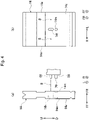
- the photoelectric sensor 68 is configured to emit an inspection beam B and detect the engagement hole 14h of the die tool 14 from a result of receiving a reflected beam of the inspection beam B, in a state of being located at the same height as the engagement hole 14h of the die tool 14.
- a two-dimensional code reader 70 as an information reader is provided, and the two-dimensional code reader 70 reads tool identification information about a die tool 14 from an identification mark 14m in a state of being located at the same height as the identification mark 14m.
- the two-dimensional code reader 70 to read tool information about the die tool 14 via the tool identification information about the die tool 14 is provided.
- the photoelectric sensor 68 and the two-dimensional code reader 70 may be provided on the lower unit body 56 instead of being provided on the lower support member 58.
- an upper guide 72 extending in the left-right direction is provided on the back side of the upper tool holder 34, and the upper guide 72 projects to the right of the upper joint block 40.
- a pair of upper tool exchange units 74 as upper moving bodies are provided being movable in the left-right direction via the upper guide 72.
- the upper tool exchange units 74 transport punch tools 12 between the upper tool holder 34 and an upper stocker 46 positioned at the upper tool exchange position.
- Each upper tool exchange unit 74 moves in the left-right direction relative to the upper table 26 by driving of a servo motor 76 as a left-right moving actuator provided at an appropriate position on the upper tool exchange unit 74.
- the servo motor 76 has an encoder 78 as a position detector to detect a position of the upper tool exchange unit 74 in the left-right direction.
- Each upper tool exchange unit 74 is in a publicly known configuration as shown in Patent Literatures 2 and 3, and has an upper unit body 80 provided on the upper guide 72 being movable in the left-right direction and an upper support member 82 provided on the upper unit body 80 being movable in the front-back direction and in the vertical direction.
- the upper support member 82 moves in the front-back direction relative to the upper unit body 80 by driving of an air cylinder 84 as a front-back moving actuator provided at an appropriate position on the upper unit body 80.
- the upper support member 82 moves in the vertical direction relative to the upper unit body 80 by driving of an air cylinder 86 as a vertically moving actuator provided at an appropriate position on the upper unit body 80.
- Each upper tool exchange unit 74 has an upper tool retention member (an upper hook member) 88 provided on the upper support member 82 being movable in the front-back direction, and the upper tool retention member 88 is engageable with and disengageable from the engagement hole 12h of a punch tool 12.
- the upper tool retention member 88 moves in the front-back direction relative to the upper support member 82 by driving of an air cylinder 90 as another front-back moving actuator provided at an appropriate position on the upper support member 82.
- a photoelectric sensor 92 is provided as a hole detector to detect the engagement hole 12h of a punch tool 12 fitted to the upper tool holder 34.
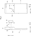
- the photoelectric sensor 92 is configured to emit an inspection beam B and detect the engagement hole 12h of the punch tool 12 from a result of receiving a reflected beam of the inspection beam B, in a state of being located at the same height as the engagement hole 12h of the punch tool 12.
- a two-dimensional code reader 94 as an information reader is provided, and the two-dimensional code reader 94 reads identification information about a punch tool 12 from an identification mark 12m in a state of being located at the same height as the identification mark 12m.
- the two-dimensional code reader 94 to read tool information about the punch tool 12 via the identification information about the punch tool 12 is provided.
- the photoelectric sensor 92 and the two-dimensional code reader 94 may be provided on the upper unit body 80 instead of being provided on the upper support member 82.
- the bending system 10 includes a database 96 storing tool information about the plurality of die tools 14 and tool information about the plurality of punch tools 12.
- the tool information about the plurality of die tools 14 is associated with identification information about the plurality of die tools 14 in the database 96.
- the tool information about the plurality of punch tools 12 is associated with identification information about the plurality of punch tools 12 in the database 96.
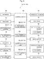
- the bending system 10 includes a control device 98 to control the hydraulic cylinders 28 and the like based on a processing program and controls the lower tool exchange units 50 and the like based on a tool exchange program.
- the control device 98 is configured with a computer, and the encoders 54, the photoelectric sensors 68, the two-dimensional code readers 70, the encoders 78, the photoelectric sensors 92, the two-dimensional code readers 94, the database 96 and the like are connected to the control device 98.
- the control device 98 has a memory (not shown) storing the processing program, the tool exchange program and the like, and a CPU (not shown) that executes the processing program and the tool exchange program.
- the processing program and the tool exchange program include layout information showing a layout state of die tools 14 and layout information showing a layout state of die tools 14 on each lower stocker 44.
- the processing program and the tool exchange program include layout information showing a layout state of the punch tools 12 and layout information showing a layout state of the punch tools 12 on each upper stocker 46.
- the CPU of the control device 98 demonstrates functions as a hole position acquisition unit 100, a tool information acquisition unit 102, a retry control unit 104 and a layout control unit 106.
- Specific content of functions of the hole position acquisition unit 100, the tool information acquisition unit 102, the retry control unit 104 and the layout control unit 106 are as below.
- the hole position acquisition unit 100 acquires positions of centers of the engagement holes 14h of the die tools 14 in the left-right direction by calculation.
- the hole position acquisition unit 100 acquires the positions of the centers of the engagement holes 14h of the die tools 14 in the left-right direction in consideration of relative positions of the photoelectric sensors 68 relative to the lower unit bodies 56.
- the hole position acquisition unit 100 acquires positions of centers of the engagement holes 12h of the punch tools 12 in the left-right direction by calculation.
- the hole position acquisition unit 100 acquires the positions of the centers of the engagement holes 12h of the punch tools 12 in the left-right direction in consideration of a relative positions of the photoelectric sensors 92 relative to the upper unit bodies 80.
- the tool information acquisition unit 102 acquires tool information about the die tools 14, including width dimensions of the die tools 14 in the left-right direction and relative positions of the centers of the engagement holes 14h, based on identification information about the die tools 14 from the two-dimensional code readers 70. Similarly, referring to the database 96, the tool information acquisition unit 102 acquires tool information about the punch tools 12, including width dimensions of the punch tools 12 in the left-right direction and relative positions of the centers of the engagement holes 12h, based on identification information about the punch tools 12 from the two-dimensional code readers 94.
- the retry control unit 104 executes a retry process of the lower tool exchange unit 50 and the like as below.
- the failure in the operation of retaining the die tool 14 by the lower tool retention member 64 is judged by the fact that the air cylinder 60 or 66 has not reached a stroke end. If the operation of retaining the die tool 14 by the lower tool retention member 64 fails, an alarm occurs.
- the retry control unit 104 controls the servo motor 52 so that the lower tool exchange unit 50 moves in the left-right direction (for example, in the left direction) relative to the lower table 24 by an amount corresponding to a relative position of the engagement hole 14h of the die tool 14, which is tool information about the die tool 14 acquired immediately after the alarm occurs (see Figure 7A(a) ).
- the retry control unit 104 controls the servo motor 52 so that the lower tool exchange unit 50 moves in the left-right direction (for example, in the right direction) relative to the lower table 24 near a position where the alarm occurred (see Figure 7A(b) and 7B(a)).
- the retry control unit 104 controls the lower tool exchange unit 50 to retry the operation of retaining the die tool 14 by the lower tool retention member 64 (see Figure 7B(b) ).
- the retry control unit 104 also executes the retry process of the upper tool exchange unit 74 and the like similarly to the above.
- the layout control unit 106 executes a layout process of the lower tool exchange units 50 and the like as below. Similarly, if a plurality of die tools 14 are randomly fitted to the lower tool holder 30 by manual work of a worker, the layout control unit 106 also executes the layout process of the lower tool exchange units 50 and the like as necessary.
- the layout control unit 106 controls the servo motors 52 so that the lower tool exchange units 50 move in the left-right direction (for example, in the right direction) relative to the lower table 24 from the side of the lower table 24 (see Figures 8A(a) and 8A(b) and Figure 8B(a) ). After that, based on acquired positions of the centers of the engagement holes 14h of the plurality of die tools 14 in the left-right direction and tool layout information about the plurality of die tools 14, the layout control unit 106 controls the lower tool exchange units 50 to lay out again the plurality of die tools 14 at regular arrangement positions on the lower tool holder 30 (see Figure 8B(b) ).
- the layout control unit 106 controls the lower tool exchange units 50 to remove the plurality of die tools 14 from the lower tool holder 30 and lay out them at regular arrangement positions on the lower stocker 44 as necessary.
- the layout control unit 106 also executes a layout process of the upper tool exchange units 74 and the like similarly to the above.
- the control device 98 controls the servo motor 52 to cause the lower tool exchange units 50 to move in the left-right direction and causes the lower tool retention members 64 to face the engagement holes 14h of the die tools 14 fitted to the lower tool holder 30. Then, while causing the lower tool retention members 64 to be engaged with the engagement holes 14h of the die tools 14, the control device 98 causes the lower tool retention members 64 to retain the die tools 14. Furthermore, the control device 98 controls the lower tool exchange units 50 to remove the die tools 14 from the lower tool holder 30. The die tools 14 may be removed from the lower tool holder 30 by being caused to slide in the right direction on the lower tool holder 30.
- control device 98 controls the servo motors 52 to cause the lower tool exchange units 50 to move in the right direction and cause the lower tool retention members 64 to be located at positions corresponding to the lower stocker 44 positioned at the lower tool exchange position. Then, the control device 98 controls the lower tool exchange units 50 to fit the die tools 14 to the lower stocker 44. After that, the control device 98 causes the lower tool retention members 64 to be disengaged from the engagement holes 14h of the die tools 14 and releases the state of retaining the die tools 14 by the lower tool retention members 64. The die tool 14 may be fitted to the lower stocker 44 by being caused to slide in the right direction on the lower joint block 38.
- the tool information acquisition unit 102 acquires tool information about the die tool 14 including a relative position of the engagement hole 14h of the die tool 14, based on identification information about the die tool 14 from the two-dimensional code reader 70. Then, the retry control unit 104 controls the servo motor 52 to cause the lower tool exchange unit 50 to move in the left-right direction (for example, in the left direction) relative to the lower table 24 by an amount corresponding to the relative position of the engagement hole 14h of the die tool 14 (see Figure 7A(a) ). The tool information acquisition unit 102 may acquire tool information about the die tool 14 based on a detection result from the encoder 54 at the time of the occurrence of the alarm and layout information about the die tool 14.
- the retry control unit 104 controls the servo motor 52 to cause the lower tool exchange unit 50 to move in the left-right direction near the alarm occurrence position while monitoring detection results from the encoder 54 (see Figure 7A(b) ). Further, during the movement of the lower tool exchange unit 50, the photoelectric sensor 68 emits an inspection beam B and detects the engagement hole 14h of the die tool 14 from a result of receiving a reflected beam of the inspection beam B (see Figure 7B(a) ).
- the hole position acquisition unit 100 acquires a position of the center of the engagement hole 14h of the die tool 14 in the left-right direction.
- the retry control unit 104 controls the lower tool exchange unit 50 to retry the operation of retaining the die tool 14 by the lower tool retention member 64 (see Figure 7B (b) ). Thereby, it is possible to continue the operation related to the transportation of the die tools 14 by the lower tool exchange units 50.
- the layout control unit 106 controls the servo motors 52 to cause the lower tool exchange units 50 to move in the left-right direction (for example, in the right direction) relative to the lower table 24 from the side of the lower table 24 while monitoring detection results from the encoders 54 (see Figure 8A(a) and 8A(b) and Figure 8B(a) ).
- the photoelectric sensors 68 emit inspection beams B and detect the engagement holes 14h of the plurality of die tools 14 from results of receiving reflected beams of the inspection beams B.
- the hole position acquisition unit 100 acquires positions of the centers of the engagement holes 14h of the plurality of die tools 14 in the left-right direction (see Figure 8A(b) ). Thereby, the bending system 10 can recognize an actual layout state of the plurality of die tools 14 on the lower tool holder 30.
- the tool information acquisition unit 102 may acquire tool information about the plurality of die tools 14.
- the layout control unit 106 controls the lower tool exchange units 50 to lay out again the plurality of die tools 14 at regular arrangement positions on the lower tool holder 30 (see Figure 8B(b) ).
- the layout control unit 106 controls the lower tool exchange units 50 to remove the plurality of die tools 14 from the lower tool holder 30 and lay out them at regular arrangement positions on the lower stocker 44. Thereby, it is possible to continue the operation related to the transportation of the die tools 14 by the lower tool exchange units 50.
- the photoelectric sensors 68 detect the end faces 14e of die tools 14 on the middle side.
- the bending system 10 can determine whether there are gaps among the plurality of die tools 14, based on tool layout information about the plurality of die tools 14.
- the hole position acquisition unit 100 acquires positions of the centers of the engagement holes 14h of the die tools 14 in the left-right direction by calculation, as mentioned above. Based on positions of the upper tool exchange units 74 in the left-right direction at the time of the engagement holes 12h of punch tools 12 being detected by the photoelectric sensors 92 and the like, the hole position acquisition unit 100 acquires positions of the centers of the engagement holes 12h of the punch tools 12 in the left-right direction.
- the tool information acquisition unit 102 acquires tool information about die tools 14 based on identification information about the die tools 14 from the two-dimensional code readers 70.
- the tool information acquisition unit 102 acquires tool information about punch tools 12 based on identification information about the punch tools 12 from the two-dimensional code readers 94.
- the bending system 10 can accurately recognize actual positions of the engagement holes 14h of a plurality of die tools 14 in the left-right direction on the lower tool holder 30 and actual positions of the engagement holes 12h of a plurality of punch tools 12 in the left-right direction on the upper tool holder 34.
- the first embodiment it is possible to stabilize automatic operation of the bending system 10 without the operation related to transportation of die tools 14 by the lower tool exchange units 50 and the like being interrupted in the middle of the operation and the like.
- a bending system 108 according to a second embodiment has a configuration similar to that of the bending system 10 according to the first embodiment except for a part thereof.
- components of the bending system 108 components different from those of the bending system 10 will be explained.
- components corresponding to components of the bending system 10 are given the same reference signs in drawings.
- a photoelectric sensor 110 is provided as an end face detector to detect the end face 14e of a die tool 14 fitted to the lower tool holder 30 instead of the photoelectric sensor 68 (see Figure 4 ).
- the photoelectric sensor 110 is configured to emit an inspection beam B and detect the end face 14e of the die tool 14 from a result of receiving a reflected beam of the inspection beam B, in a state of being located at the same height as a part higher than the engagement hole 14h on the die tool 14.
- the photoelectric sensor 110 may detect the end face 14e of the die tool 14 in a state of being located at the same height as the engagement hole 14h of the die tool 14. In this case, the control device 98 judges which of the end face 14e and engagement hole 14h of the die tool 14 the detection target of the photoelectric sensor 110 is, based on tool layout information and the like about a plurality of die tools 14.
- a photoelectric sensor 112 is provided as an end face detector to detect the end face 12e of a punch tool 12 fitted to the upper tool holder 34 instead of the photoelectric sensor 92 (see Figure 5 ).
- the photoelectric sensor 112 is configured to emit an inspection beam B and detect the end face 12e of the punch tool 12 from a result of receiving a reflected beam of the inspection beam B, in a state of being located at the same height as a part lower than the engagement hole 12h on the punch tool 12.
- the photoelectric sensor 112 may detect the end face 12e of the punch tool 12 in a state of being located at the same height as the engagement hole 12h of the punch tool 12. In this case, the control device 98 judges which of the end face 12e and engagement hole 12h of the punch tool 12 the detection target of the photoelectric sensor 110 is, based on tool layout information and the like about a plurality of punch tools 12.
- the control device 98 has a hole position acquisition unit 114, a retry control unit 116 and a layout control unit 118 instead of the hole position acquisition unit 100, the retry control unit 104 and the layout control unit 106.
- Specific content of functions of the hole position acquisition unit 114, the retry control unit 116 and the layout control unit 118 are as below.
- the hole position acquisition unit 114 acquires positions of the centers of the engagement holes 14h of the die tools 14 in the left-right direction by calculation.
- the hole position acquisition unit 114 acquires the positions of the centers of the engagement holes 14h of the die tools 14 in the left-right direction in consideration of relative positions of the photoelectric sensors 110 relative to the lower unit bodies 56.
- the hole position acquisition unit 114 acquires positions of the centers of the engagement holes 12h of the punch tools 12 in the left-right direction by calculation.
- the hole position acquisition unit 114 acquires the positions of the centers of the engagement holes 12h of the punch tools 12 in the left-right direction in consideration of relative positions of the photoelectric sensors 112 relative to the upper unit bodies 80.
- the retry control unit 116 executes a retry process of the lower tool exchange unit 50 and the like as below.
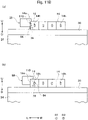
- the retry control unit 116 controls the servo motor 52 so that the lower tool exchange unit 50 moves in the left-right direction (for example, in the left direction) relative to the lower table 24 by an amount corresponding to a relative position of the engagement hole 14h of the die tool 14, which is tool information about the die tool 14 acquired immediately after an alarm occurs (see Figure 11A(a) ).
- the retry control unit 116 controls the servo motor 52 so that the lower tool exchange unit 50 moves in the left-right direction (for example, in the right direction) relative to the lower table 24 from the side of the die tool 14 (see Figure 11A(b) and 11B(a) ).
- the retry control unit 116 controls the lower tool exchange unit 50 to retry the operation of retaining the die tool 14 by the lower tool retention member 64 (see Figure 11B (b) ).
- the retry control unit 116 also executes the retry process of the upper tool exchange unit 74 and the like similarly to the above.
- the layout control unit 118 executes a layout process of the lower tool exchange units 50 and the like as below. Similarly, if a plurality of die tools 14 are randomly fitted to the lower tool holder 30 by manual work of a worker, the layout control unit 118 also executes the layout process of the lower tool exchange units 50 and the like as necessary.
- the layout control unit 118 controls the servo motors 52 so that the lower tool exchange units 50 move in the left-right direction (for example, in the right direction) relative to the lower table 24 from the side of the lower table 24 (see Figures 12A(a) and 12A(b) and Figure 12B(a) ).
- the layout control unit 106 controls the lower tool exchange units 50 to lay out again the plurality of die tools 14 at regular arrangement positions on the lower tool holder 30 (see Figure 12B(b) ).
- the layout control unit 118 controls the lower tool exchange units 50 to remove the plurality of die tools 14 from the lower tool holder 30 and lay out them at regular arrangement positions on the lower stocker 44 as necessary.
- the layout control unit 118 also executes a layout process of the upper tool exchange units 74 and the like similarly to the above.
- the tool information acquisition unit 102 acquires tool information about the die tool 14 including a relative position of the engagement hole 14h of the die tool 14, based on identification information about the die tool 14 from the two-dimensional code reader 70. Then, the retry control unit 116 controls the servo motor 52 to cause the lower tool exchange unit 50 to move in the left-right direction (for example, in the left direction) relative to the lower table 24 by an amount corresponding to the relative position of the engagement hole 14h of the die tool 14 (see Figure 11A(a) ). The tool information acquisition unit 102 may acquire tool information about the die tool 14 based on a detection result from the encoder 54 at the time of the occurrence of the alarm and layout information about the die tool 14.
- the retry control unit 116 controls the servo motor 52 to cause the lower tool exchange unit 50 to move in the left-right direction (for example, in the right direction) from the side of the die tool 14 while monitoring detection results from the encoder 54 (see Figure 11A(b) ). Further, during the movement of the lower tool exchange unit 50, the photoelectric sensor 110 emits an inspection beam B and detects the end face 14e of the die tool 14 from a result of receiving a reflected beam of the inspection beam B (see Figure 11B(a) ).
- the hole position acquisition unit 114 acquires a position of the center of the engagement hole 14h of the die tool 14 in the left-right direction.
- the retry control unit 116 controls the lower tool exchange unit 50 to retry the operation of retaining the die tool 14 by the lower tool retention member 64 (see Figure 11B (b) ). Thereby, it is possible to continue the operation related to the transportation of the die tools 14 by the lower tool exchange units 50.
- the layout control unit 118 controls the servo motors 52 to cause the lower tool exchange units 50 to move in the left-right direction (for example, in the right direction) relative to the lower table 24 from the side of the lower table 24 (see Figure 12A(a) and 12A(b) and Figure 12B(a) ).
- the photoelectric sensors 110 emit inspection beams B and detect the end face 14e of a die tool 14 on the left end side from results of receiving reflected beams of the inspection beams B.
- the tool information acquisition unit 102 acquires tool information about the plurality of die tools 14 (width dimensions of the die tools 14 in the left-right direction and relative positions of the centers of the engagement holes 14h).
- the hole position acquisition unit 114 acquires positions of the centers of the engagement holes 14h of the plurality of die tools 14 in the left-right direction (see Figure 12A(b) ). Thereby, the bending system 10 can recognize an actual layout state of the plurality of die tools 14 on the lower tool holder 30.
- the layout control unit 118 controls the lower tool exchange units 50 to lay out again the plurality of die tools 14 at regular arrangement positions on the lower tool holder 30 (see Figure 12B(b) ).
- the layout control unit 118 controls the lower tool exchange units 50 to remove the plurality of die tools 14 from the lower tool holder 30 and lay out them at regular arrangement positions on the lower stocker 44. Thereby, it is possible to continue the operation related to the transportation of the die tools 14 by the lower tool exchange units 50.
- the photoelectric sensors 110 detect the end faces 14e of die tool 14 on the middle side.
- the bending system 10 can determine whether there are gaps among the plurality of die tools 14, based on tool layout information about the plurality of die tools 14.
- the hole position acquisition unit 100 acquires positions of the centers of the engagement holes 14h of the die tools 14 in the left-right direction by calculation, as mentioned above. Based on positions of the upper tool exchange units 74 in the left-right direction at the time of the engagement holes 12h of punch tools 12 being detected by the photoelectric sensors 92 and the like, the hole position acquisition unit 100 acquires positions of the centers of the engagement holes 12h of the punch tools 12 in the left-right direction.
- the tool information acquisition unit 102 acquires tool information about die tools 14 based on identification information about the die tools 14 from the two-dimensional code readers 70.
- the tool information acquisition unit 102 acquires tool information about punch tools 12 based on identification information about the punch tools 12 from the two-dimensional code readers 94.
- the bending system 10 can accurately recognize actual positions of the engagement holes 14h of a plurality of die tools 14 in the left-right direction on the lower tool holder 30 and actual positions of the engagement holes 12h of a plurality of punch tools 12 in the left-right direction on the upper tool holder 34.
- the second embodiment it is possible to stabilize automatic operation of the bending system 10 without the operation related to transportation of die tools 14 by the lower tool exchange units 50 and the like being interrupted in the middle of the operation and the like.
- a bending system 120 uses torque sensors 122 to detect torques of the servo motors 52 as end face detectors to detect the end faces 14e of die tools 14, instead of the photoelectric sensors 110 (see Figure 6 ).
- Each torque sensors 122 is configured to detect the end face 14e of a die tool 14 when a detected torque of its corresponding servo motor 52 (a detection result) exceeds a predetermined threshold.
- the bending system 120 uses torque sensors 124 to detect torques of servo motors 75 as end face detectors to detect the end faces 12e of punch tools 12, instead of the photoelectric sensors 112 (see Figure 6 ).
- Each torque sensor 124 is configured to detect the end face 12e of a punch tool 12 when a detected torque of the servo motor 75 exceeds a predetermined threshold.
- control device 98 has an end face detection control unit 126 and has a hole position acquisition unit 128 instead of the hole position acquisition unit 100 (see Figure 6 ).
- Specific content of functions of the end face detection control unit 126 is as below.
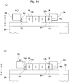
- the end face detection control unit 126 controls one lower tool exchange unit 50 so that one lower tool retention member 64 faces an end face 14e on one side of the die tools 14 (for example, an end face on the left side) in the left-right direction (see Figure 14(a) ). Further, before detecting the end face 14e on the one side of the die tools 14, the end face detection control unit 126 controls the other lower tool exchange unit 50 so that the other lower tool retention member 64 retains an engagement hole 14h on the other side of the die tools 14, or the retention state is continued (see Figure 14 (a) and (b) ).
- the end face detection control unit 126 controls the other lower tool exchange unit 50 so that the other lower tool retention member 64 is in contact with or close to the end face 14e on the other side (for example, an end face on the right side) of the die tools 14.
- the end face detection control unit 126 controls one upper tool exchange unit 74 so that one upper tool retention member 88 faces an end face 12e on one side of the punch tools 12 (for example, an end face on the left side) in the left-right direction. Further, before detecting the end face 12e on the one side of the punch tools 12, the end face detection control unit 126 controls the other upper tool exchange unit 74 so that the other upper tool retention member 88 retains the engagement hole 12h of a punch tool 12, or the retention state is maintained.
- the end face detection control unit 126 controls the other upper tool exchange unit 74 so that the other upper tool retention member 88 is in contact with or close to an end face 12e on the other side (for example, an end face on the right side) of the punch tools 12.
- the hole position acquisition unit 128 Based on a position of the one lower tool exchange unit 50 in the left-right direction at the time of the end face 14e on the one side of the die tools 14 being detected, and acquired tool information about the die tool 14 (a relative position of the engagement hole 14h of the die tool 14), the hole position acquisition unit 128 acquires a position of the center of the engagement hole 14h of the die tool 14 in the left-right direction by calculation. The hole position acquisition unit 128 acquires the position of the center of the engagement hole 14h of the die tool 14 in the left-right direction in consideration of a relative position of the one lower tool retention member 64 relative to the lower unit body 56.
- the hole position acquisition unit 128 acquires a position of the center of the engagement hole 12h of the punch tool 12 in the left-right direction by calculation.
- the hole position acquisition unit 128 acquires the position of the center of the engagement hole 12h of the punch tool 12 in the left-right direction in consideration of a relative position of the one upper tool retention member 88 relative to the upper unit body 80.
- the bending system 120 performs an operation related to detection of the end faces 14e of the die tools 14 as below.
- the end face detection control unit 126 controls one lower tool exchange unit 50 so that one lower tool retention member 64 faces one end face 14e of a die tool 14 on the left end side in the left-right direction. Further, the end face detection control unit 126 controls the other lower tool exchange unit 50 so that the other lower tool retention member 64 retains the engagement hole 14h of a die tool 14 on the right end side, or the retention state is continued (see Figure 14(a) ). Alternatively, the end face detection control unit 126 controls the other lower tool exchange unit 50 so that the other lower tool retention member 64 is in contact with or close to the other end face 14e of the die tool 14 on the right end side.
- the retry control unit 116 or a layout control unit 119 controls the servo motors 52 to cause the lower tool exchange units 50 to move in the left-right direction (for example, in the right direction) from the side of the die tools 14 while monitoring detection results from the encoders 54.
- the one lower tool retention member 64 comes into contact with the one end face 14e of the die tool 14 on the left end side; a detection torque of one servo motor 52 exceeds the predetermined threshold; and one torque sensor 122 detects the one end face 14e of the die tool 14 on the left end side (see Figure 14(b) ).
- the hole position acquisition unit 114 acquires a position of the center of the engagement hole 14h of the die tool 14 on the left end side in the left-right direction by calculation.
- the hole position acquisition unit 114 acquires a position of the center of the engagement hole 14h of the die tool 14 on the right end side in the left-right direction by calculation.
- the bending system 120 performs an operation related to detection of the end face 12e of a punch tool 12 similarly to the above.
- the bending system 130 does not include the tool exchange units 50 or 74 (see Figure 6 ), the tool rack 42 (see Figure 6 ), the servo motors 52 or 76 (see Figure 6 ) or the like.
- the photoelectric sensors 110 and the two-dimensional code readers 70 are provided at appropriate positions on sliders 132 with back gauge mechanisms as moving bodies, respectively.
- Servo motors 134 as left-right moving actuators to cause the sliders 132 to move in the left-right direction are connected to the control device 98 of the bending system 130.
- Encoders 136 as position detectors to detect positions of the sliders 132 in the left-right direction are connected to the control device 98 of the bending system 130.
- the control device 98 of the bending system 120 includes a tool position acquisition unit 138 instead of the hole position acquisition unit 114 (see Figure 6 ). Based on positions of the sliders 132 in the left-right direction at the time of the end faces 14e (see Figure 9 ) of die tools 14 being detected, and acquired tool information (width dimensions of the die tools 14 in the left-right direction) about the die tools 14 (see Figure 1 ), the tool position acquisition unit 138 acquires positions of the end faces 14e of the die tools 14 in the left-right direction by calculation.
- the tool position acquisition unit 138 acquires positions of the end faces 12e of the punch tools 12 in the left-right direction by calculation.
- the bending system 130 can accurately recognize actual positions of end faces 14e of a plurality of die tools 14 in the left-right direction on the lower tool holder 30 (see Figure 1 ) and actual positions of end faces 12e of a plurality of punch tools 12 in the left-right direction on the upper tool holder 34 (see Figure 1 ).
- a die tool 14 does not need to have an engagement hole 14h, and a punch tool 12 does not need to have an engagement hole 12h.
- the present disclosure is not limited to the explanations of the first to fourth embodiment described above.
- the present disclosure can be implemented in various aspects as below.
- holes 14h of die tools 14 cameras to pick up images of the engagement holes 14h of the die tools 14 may be used instead of using the photoelectric sensors 68. In this case, using a reference image for the engagement holes 14h of the die tools 14, the hole position acquisition unit 100 judges whether a picked-up image corresponds to the reference image or not by pattern matching. Similarly, as hole detectors to detect the engagement hole 12h of punch tools 12, cameras to pick up images of the engagement holes 12h of the punch tools 12 may be used instead of using the photoelectric sensors 92.
- an IC chip storing tool information about the die tool 14 may be attached.
- an IC chip storing tool information about the punch tool 12 may be attached.
- an IC chip reader as an information reader reads the tool information about the die tool 14 and the tool information about the punch tool 12.
- the photoelectric sensors 68 (or 108) and the two-dimensional code readers 70 may be provided on sliders (see Figure 13 ) with back gauge mechanisms as moving bodies provided on the back side of the lower table 24 being movable in the left-right direction, instead of being provided on the lower tool exchange units 50.
- the photoelectric sensors 68 (or 108) and the two-dimensional code readers 70 may be provided on bending indicators (not shown) as moving bodies provided on the front side of the lower table 24 being movable in the left-right direction.
- the operation related to tool exchange may be performed by a tool change robot (not shown) instead of performing the operation related to tool exchange by the lower tool exchange units 50 and the upper tool exchange units 74.
Landscapes
- Engineering & Computer Science (AREA)
- Mechanical Engineering (AREA)
- Mounting, Exchange, And Manufacturing Of Dies (AREA)
- Bending Of Plates, Rods, And Pipes (AREA)
Abstract
Description
- The present disclosure relates to a bending system for performing bending for a plate-shaped workpiece (a sheet metal).
- A bending system includes a press brake to perform bending for a workpiece, and the press brake includes upper and lower tables and tool holders provided on the respective tables and configured to retain tools. Further, the bending system includes a tool rack arranged on the side of the press brake and configured to store a plurality of tools. The tool rack has a plurality of stockers for retaining tools in which selected arbitrary stockers are configured such that the stockers can be positioned at exchange positions for performing tool exchange. Furthermore, the bending system includes tool exchange units for transporting tools between the tool holders and stockers positioned at the exchange positions, and each tool exchange unit has a tool retention member that is engageable with and disengageable from an engagement hole of a tool (see Patent Literature 1).
- As prior-art techniques related to the present disclosure, techniques shown in Patent Literatures 2 to 4 exist in addition to the technique of Patent Literature 1.
-
- Patent Literature 1:
Japanese Patent No. 5947861 - Patent Literature 2:
Japanese Patent No. 4672868 - Patent Literature 3:
Japanese Patent No. 4558852 - Patent Literature 4:
Japanese Patent Application Laid-Open Publication No. 2003-71519 - A conventional bending system does not recognize actual positions of tools in a left-right direction on tool holders. Therefore, the conventional bending system has the following problem.
- For example, if a tool is fitted to a position deviated from a regular arrangement position on a tool holder corresponding to tool layout information, and engagement or disengagement of a tool retention member with an engagement hole of a tool (a retention operation) fails, an alarm occurs, and an operation related to tool transportation by a tool exchange unit stops. Further, for example, if a clamp plate or a clamper of a tool holder is accidentally released after tools are fitted to the tool holder, there is a possibility that the tools slightly move and are displaced from regular arrangement positions on the tool holder, and, therefore, it is not possible to perform the operation related to tool transportation by a tool exchange unit. Furthermore, for example, tools are randomly laid out on a tool holder by manual work or the like, it is not possible to lay out again the tools at the regular arrangement positions on the tool holder by a tool exchange unit. That is, in the former case, there is a problem that it becomes difficult to stabilize automatic operation of the bending system. Here, the operation related to tool transportation is assumed to include an operation of exchanging tools fitted to a tool holder with tools fitted to a stocker, an operation of retaining a tool by a tool retention member and an operation of laying out tools on a tool holder or a stocker.
- In a case where tools are randomly laid out on a tool holder by manual work or the like in a general-purpose bending system without tool exchange units, problems similar to the above also occur.
- Therefore, an object of the present disclosure is to provide a bending system capable of accurately recognizing actual positions of tools in a left-right direction on a tool holder or on a stocker.
- A bending system according to a first aspect of one or more embodiments includes: a moving body provided on a back side or a front side of a table of a press brake so as to be movable in a left-right direction; a moving actuator configured to cause the moving body to move in the left-right direction relative to the table; and a position detector configured to detect a position of the moving body in the left-right direction. The bending system according to a first embodiment includes: a hole detector provided on the moving body and configured to detect an engagement hole for causing a tool retention member of a tool exchange unit to be engaged and disengaged, the engagement hole being a part of a tool fitted to a tool holder provided on the table; and a hole position acquisition unit configured to acquire a position of the engagement hole of the tool in the left-right direction, based on the position of the moving body in the left-right direction at the time of the engagement hole of the tool being detected.
- The bending system according to the first aspect may further include an information reader provided on the moving body and configured to read, from a storage medium provided to the tool, tool information including a width dimension of the tool in the left-right direction and a relative position of the engagement hole in the tool.
- According to the first aspect, the moving body is moved in the left-right direction relative to the table by driving of the moving actuator while the position of the moving body in the left-right direction is being detected by the position detector. Further, during the movement of the moving body, the engagement hole of the tool is detected by the tool detector. Then, the hole position acquisition unit acquires the position of the engagement hole of the tool in the left-right direction, based on the position of the moving body in the left-right direction at the time of the engagement hole of the tool being detected. Thereby, the bending system can recognize an actual position of the engagement hole of the tool in the left-right direction on the tool holder.
- A bending system according to a second aspect of one or more embodiments further includes: a moving body provided on a back side or a front side of a table of a press brake so as to be movable in a left-right direction; a moving actuator configured to cause the moving body to move in the left-right direction relative to the table; and a position detector configured to detect a position of the moving body in the left-right direction. The bending system according to the second aspect includes: an end face detector provided on the moving body and configured to detect an end face of a tool fitted to a tool holder provided on the table; and an information reader provided on the moving body and configured to read, from a storage medium provided to the tool, tool information including a width dimension of the tool in the left-right direction and a relative position of an engagement hole in the tool, the engagement hole being a part of the tool and being for causing a tool retention member of a tool exchange unit to be engaged and disengaged. The bending system according to the second aspect further includes: a hole position acquisition unit configured to acquire a position of the engagement hole of the tool in the left-right direction, based on the position of the moving body in the left-right direction at the time of the end face of the tool being detected, and the read tool information about the tool.
- According to the second aspect, the moving body is moved in the left-right direction by driving of the moving actuator while the position of the moving body in the left-right direction is being detected by the position detector. During the movement of the moving body, the end face of the tool is detected by the tool detector, and the tool information about the tool is read by the information reader. Then, the hole position acquisition unit acquires the position of the engagement hole of the tool in the left-right direction, based on the position of the moving body in the left-right direction at the time of the end face of the tool being detected, and the read tool information about the tool. Thereby, the bending system can recognize an actual position of the engagement hole of the tool in the left-right direction on the tool holder.
- A bending system according to a third aspect of one or more embodiments includes: a moving body provided on a back side or a front side of a table of a press brake so as to be movable in a left-right direction; a moving actuator configured to cause the moving body to move in the left-right direction relative to the table; and a position detector configured to detect a position of the moving body in the left-right direction. The bending system according to the third aspect further includes: an end face detector provided on the moving body and configured to detect an end face of a tool fitted to a tool holder provided on the table; and an information reader provided on the moving body and configured to read, from a storage medium provided to the tool, tool information including a width dimension of the tool in the left-right direction. The bending system according to the third aspect further includes a tool position acquisition unit configured to acquire a position of the tool in the left-right direction (a position of the end face of the tool in the left-right direction or a position of the center of the tool in the left-right direction), based on the position of the moving body in the left-right direction at the time of the end face of the tool being detected, and the read tool information about the tool.
- The bending system according to the third aspect may further include an information reader provided on the moving body and configured to read, from a storage medium provided to the tool, tool information including a width dimension of the tool in the left-right direction.
- According to the third aspect, the moving body is moved in the left-right direction by driving of the moving actuator while the position of the moving body in the left-right direction is being detected by the position detector. During the movement of the moving body, the engagement hole of the tool is detected by the hole detector, and the tool information about the tool is read by the information reader. Then, the tool position acquisition unit acquires the position of the tool in the left-right direction, based on the position of the moving body in the left-right direction at the time of the engagement hole of the tool being detected, and the read tool information about the tool. Thereby, the bending system can recognize an actual position of the tool in the right direction on the tool holder.
- According to the present disclosure, it is possible to accurately recognize an actual positions of a tool in a left-right direction on a tool holder or stocker.
-
- [
Figure 1] Figure 1 is a schematic front view of a bending system according to first and second embodiments. - [
Figure 2] Figure 2 is a schematic right side view of the bending system according to the first embodiment, and shows that die tools are retained by a lower tool retention member, and punch tools are retained by an upper tool retention member. InFigure 2 , a lower joint block and an upper joint block are omitted. - [
Figure 3] Figure 3 is an enlarged diagram of a part III inFigure 2 . - [
Figure 4] Figure 4(a) is a schematic diagram showing that an engagement hole of a die tool is being detected, and that identification information about the die tool is being read in the first embodiment.Figure 4(b) is a schematic diagram showing that a monitoring beam moves in a left-right direction in the first embodiment. - [
Figure 5] Figure 5(a) is a schematic diagram showing that an engagement hole of a punch tool is being detected, and that identification information about the punch tool is being read in the first embodiment.Figure 5(b) is a schematic diagram showing that a monitoring beam moves in the left-right direction in the first embodiment. - [
Figure 6] Figure 6 is a control block diagram of the bending system according to the first and second embodiments. - [
Figure 7A] Figures 7A(a) and7A(b) are schematic diagrams illustrating a retry process of a lower tool exchange unit and the like according to the first embodiment. - [
Figure 7B] Figures 7B(a) and 7B(b) are schematic diagrams illustrating a retry process of the lower tool exchange unit and the like according to the first embodiment. - [
Figure 8A] Figures 8A(a) and 8A(b) are schematic diagrams illustrating a layout process of the lower tool exchange unit and the like. - [
Figure 8B] Figures 8B(a) and 8B(b) are schematic diagrams illustrating a layout process of the lower tool exchange unit and the like. - [
Figure 9] Figure 9(a) is a schematic diagram showing that an end face of a die tool is being detected, and that identification information about the die tool is being read in a second embodiment.Figure 9(b) is a schematic diagram showing that a monitoring beam moves in the left-right direction in the second embodiment. - [
Figure 10] Figure 10(a) is a schematic diagram showing that an end face of a punch tool is being detected, and that identification information about the punch tool is being read in the second embodiment.Figure 10(b) is a schematic diagram showing that the monitoring beam moves in the left-right direction in the second embodiment. - [
Figure 11A] Figures 11A(a) and 11A(b) are schematic diagrams illustrating a retry process of a lower tool exchange unit and the like according to the second embodiment. - [
Figure 11B] Figures 11B(a) and 11B(b) are schematic diagrams illustrating a retry process of the lower tool exchange unit and the like according to the second embodiment. - [
Figure 12A] Figures 12A(a) and 12A(b) are schematic diagrams illustrating a layout process of the lower tool exchange unit and the like according to the second embodiment. - [
Figure 12B] Figures 12B(a) and 12B(b) are schematic diagrams illustrating a layout process of the lower tool exchange unit and the like according to the second embodiment. - [
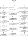
Figure 13] Figure 13 is a control block diagram of a bending system according to a third embodiment. - [
Figure 14] Figures 14(a) and 14(b) are schematic diagrams illustrating a process of detecting an end face of a die tool in the third embodiment. - [
Figure 15] Figure 15 is a control block diagram of a bending system according to a fourth embodiment. - First to fourth embodiments will be explained below with reference to
Figures 1 to 15 . - In the specification and Claims of the present application, "being provided" is assumed to include being indirectly provided via another member in addition to being directly provided. "A left-right direction" is one of horizontal directions and is synonymous with a lateral direction of a press brake, a tool rack, a tool holder or a tool. "A front-back direction" refers to a horizontal direction orthogonal to the left-right direction and is synonymous with a depth direction of the press brake or the tool rack. "Read tool information about a tool" is assumed to include reading identification information about a tool corresponding to tool information about the tool. In the drawings, "FF", "FR", "L", "R", "U" and "D" refer to a front direction, a back direction, a left direction, a right direction, an up direction and a down direction, respectively.
- As shown in
Figures 1 to 3 , abending system 10 according to a first embodiment is a system for performing bending for a plate-shaped workpiece (a sheet metal) W usingpunch tools 12 as automatically exchangeable upper tools and dietools 14 as lower tools. Further, the bendingsystem 10 includes apress brake 16 to perform bending for the workpiece W in cooperation with thepunch tools 12 and thedie tools 14. First, a configuration of thepress brake 16 will be specifically explained. - The
press brake 16 includes amain frame 18, and themain frame 18 has a pair ofside plates 20 separated in the left-right direction and facing each other, and a plurality ofcoupling members 22 to couple the pair ofside plates 20. Further, at a lower part of themain frame 18, a lower table 24 extending in the left-right direction is provided. At an upper part of themain frame 18, an upper table 26 extending in the left-right direction is provided being movable in a vertical direction. At an upper part of eachside plate 20, ahydraulic cylinder 28 is provided as a vertically moving actuator to cause the upper table 26 to move in the vertical direction relative to themain frame 18. - The lower table 24 may be configured to be movable in the vertical direction instead of configuring the upper table 26 to be movable in the vertical direction. As vertically moving actuators, servo motors (not shown) may be used instead of the
hydraulic cylinders 28. - On the upper side of the lower table 24, a
lower tool holder 30 to removably retaindie tools 14 is provided, and thelower tool holder 30 extends in the left-right direction. On thelower tool holder 30, aholder groove 30g into which shanks (bases) 14s of thedie tools 14 are to be inserted is formed along the left-right direction, theholder groove 30g being in a publicly known configuration as shown inPatent Literatures 2 and 3. Thelower tool holder 30 has ahydraulic clamper 32 to fix thedie tools 14 to the lower table 24. - Here, as shown in
Figure 4 , in the center of each dietool 14 in the left-right direction (the lateral direction), anengagement hole 14h as a part of thedie tool 14 is penetratingly formed. At positions corresponding to theengagement hole 14h (for example, on the lower side of theengagement hole 14h) on both faces (the front face and back face) of thedie tool 14, identification marks 14m as storage media storing identification information about thedie tool 14 are provided by engraving, and eachidentification mark 14m is configured with a two-dimensional code. The identification information about thedie tool 14 corresponds to tool information about thedie tool 14, and the tool information about thedie tool 14 includes a type, shape, width dimension in the left-right direction and height dimension of thedie tool 14, a relative position of the center of theengagement hole 14h in thedie tool 14 and the like. The width dimension of thedie tool 14 in the left-right direction is assumed to include a dimension from anend face 14e of thedie tool 14 to the center of thedie tool 14 in the left-right direction. The relative position of the center of theengagement hole 14h in thedie tool 14 is assumed to include a dimension from theend face 14e of thedie tool 14 to the center of theengagement hole 14h in the left-right direction and an amount of deviation of the center of theengagement hole 14h relative to the center of thedie tool 14. - As shown in
Figures 1 to 3 , anupper tool holder 34 to removably retain thepunch tools 12 is provided on the lower side of the upper table 26, and theupper tool holder 34 extends in the left-right direction. On theupper tool holder 34, aholder groove 34g into which shanks (bases) 12s ofpunch tools 12 are to be inserted is formed along the left-right direction, theholder groove 34g being in a publicly known configuration as shown inPatent Literatures 2 and 3. Theupper tool holder 34 has ahydraulic clamp plate 36 to fix thepunch tools 12 to the upper table 26. - Here, as shown in
Figure 5 , in the center of eachpunch tool 12 in the left-right direction, anengagement hole 12h as a part of thepunch tool 12 is penetratingly formed. At positions corresponding to theengagement hole 12h (for example, on the lower side of theengagement hole 12h) on both faces of thepunch tool 12, identification marks 12m as storage media storing identification information about thepunch tool 12 are provided by engraving, and eachidentification mark 12m is configured with a two-dimensional code. The identification information about thepunch tool 12 corresponds to tool information about thepunch tool 12, and the tool information about thepunch tool 12 includes a type, shape, width dimension in the left-right direction and height dimension of thepunch tool 12, a relative position of the center of theengagement hole 12h in thepunch tool 12 and the like. The width dimension of thepunch tool 12 in the left-right direction is assumed to include a dimension from anend face 12e of thepunch tool 12 to the center in the left-right direction. The relative position of the center of theengagement hole 12h in thepunch tool 12 is assumed to include a dimension from theend face 12e of thepunch tool 12 to the center of theengagement hole 12h in the left-right direction and an amount of deviation of the center of theengagement hole 12h relative to the center of thepunch tool 12. - As shown in
Figure 1 , on one side (the right side) of thelower tool holder 30 in the left-right direction, a lowerjoint block 38 extending in the left-right direction is provided. On the lowerjoint block 38, a joint groove (not shown) into which theshank 14s of adie tool 14 is to be inserted is formed along the left-right direction. The joint groove of the lowerjoint block 38 is connected to theholder groove 30g (seeFigure 3 ) of thelower tool holder 30. Further, on one side of theupper tool holder 34 in the left-right direction, an upperjoint block 40 extending in the left-right direction is provided. On the upperjoint block 40, a joint groove (not shown) into which theshank 12s of apunch tool 12 are to be inserted is formed along the left-right direction. The joint groove 40g of the upperjoint block 40 is connected to theholder groove 34g (seeFigure 3 ) of theupper tool holder 34. - As shown in
Figures 1 and2 , the bendingsystem 10 includes atool rack 42 arranged on the side (the right side) of the press brake in the left-right direction and storing a plurality ofdie tools 14 and a plurality ofpunch tools 12. Thetool rack 42 is, for example, in a publicly known configuration as shown in Patent Literatures 1 and 4. The configuration of thetool rack 42 will be simply explained. - The
tool rack 42 has a plurality oflower stockers 44 for retaining one ormore die tools 14, and the plurality oflower stockers 44 are arranged in the front-back direction. Eachlower stocker 44 extends in the left-right direction, and, on eachlower stocker 44, astocker groove 44g into which theshanks 14s ofdie tools 14 are to be inserted is formed along the left-right direction. - A configuration is made so that a selected arbitrary
lower stocker 44 is movable in the front-back direction by such a lower stocker movement mechanism (not shown) as shown in Patent Literature 1. Alternatively, the plurality oflower stockers 44 are configured to be synchronously movable in the front-back direction by such a lower stocker movement mechanism (not shown) as shown in Patent Literature 4. A configuration is made so that the selected arbitrarylower stocker 44 is positioned at a lower tool exchange position contiguous to the lowerjoint block 38 in the left-right direction, by its movement in the front-back direction. When the arbitrarylower stocker 44 is positioned at the lower tool exchange position, thestocker groove 44g of thelower stocker 44 is connected to the joint groove of the lowerjoint block 38. - The
tool rack 42 has a plurality ofupper stockers 46 for retaining one ormore punch tools 12, and the plurality ofupper stockers 46 are arranged along the front-back direction. Eachupper stocker 46 extends in the left-right direction, and, on eachupper stocker 46, astocker groove 46g into which theshanks 12s ofpunch tools 12 are to be inserted is formed along the left-right direction. - A configuration is made so that a selected arbitrary
upper stocker 46 is movable in the front-back direction by such an upper stocker movement mechanism (not shown) as shown in Patent Literature 1. Alternatively, the plurality ofupper stockers 46 are configured to be synchronously movable in the front-back direction by such an upper stocker movement mechanism (not shown) as shown in Patent Literature 4. A configuration is made so that the selected arbitraryupper stocker 46 is positioned at an upper tool exchange position contiguous to the upperjoint block 40 in the left-right direction, by its movement in the front-back direction. When the arbitraryupper stocker 46 is positioned at the upper tool exchange position, thestocker groove 46g of theupper stocker 46 is connected to the joint groove of the upperjoint block 40. - As shown in
Figures 1 to 3 , alower guide 48 extending in the left-right direction is provided on the back side (the rear side) of thelower tool holder 30, and thelower guide 48 projects to the right of the lowerjoint block 38. On the back side of the lower table 24, a pair of lowertool exchange units 50 as lower moving bodies are provided being movable in the left-right direction via thelower guide 48. The lowertool exchange units 50 transport dietools 14 between thelower tool holder 30 and alower stocker 44 positioned at the lower tool exchange position. Each lowertool exchange unit 50 moves in the left-right direction relative to the lower table 24 by driving of aservo motor 52 as a left-right moving actuator provided at an appropriate position on the lowertool exchange unit 50. Theservo motor 52 has anencoder 54 as a position detector to detect a position of the lowertool exchange unit 50 in the left-right direction. - Each lower
tool exchange unit 50 is in a publicly known configuration as shown inPatent Literatures 2 and 3, and has alower unit body 56 provided on thelower guide 48 being movable in the left-right direction and alower support member 58 provided on thelower unit body 56 being movable in the front-back direction and in the vertical direction. Thelower support member 58 moves in the front-back direction relative to thelower unit body 56 by driving of anair cylinder 60 as a front-back moving actuator provided at an appropriate position on thelower unit body 56. Thelower support member 58 moves in the vertical direction relative to thelower unit body 56 by driving of anair cylinder 62 as a vertically moving actuator provided at an appropriate position on thelower unit body 56. - Each lower
tool exchange unit 50 has a lower tool retention member (a lower hook member) 64 provided on thelower support member 58 being movable in the front-back direction, and the lowertool retention member 64 is engageable with and disengageable from theengagement hole 14h of adie tool 14. The lowertool retention member 64 moves in the front-back direction relative to thelower support member 58 by driving of anair cylinder 66 as another front-back moving actuator provided at an appropriate position on thelower support member 58. - Since an operation of retaining a
die tool 14 by the lowertool retention member 64 is commonly known as shown inPatent Literatures 2 and 3, details thereof will be omitted. - As shown in
Figures 3 and4 , at an appropriate position on eachlower support member 58, aphotoelectric sensor 68 is provided as a hole detector to detect theengagement hole 14h of adie tool 14 fitted to thelower tool holder 30. Thephotoelectric sensor 68 is configured to emit an inspection beam B and detect theengagement hole 14h of thedie tool 14 from a result of receiving a reflected beam of the inspection beam B, in a state of being located at the same height as theengagement hole 14h of thedie tool 14. - On the lower side of the
photoelectric sensor 68 on eachlower support member 58, a two-dimensional code reader 70 as an information reader is provided, and the two-dimensional code reader 70 reads tool identification information about adie tool 14 from anidentification mark 14m in a state of being located at the same height as theidentification mark 14m. In other words, on the lower side of thephotoelectric sensor 68 on thelower support member 58, the two-dimensional code reader 70 to read tool information about thedie tool 14 via the tool identification information about thedie tool 14 is provided. - The
photoelectric sensor 68 and the two-dimensional code reader 70 may be provided on thelower unit body 56 instead of being provided on thelower support member 58. - As shown in
Figures 1 to 3 , anupper guide 72 extending in the left-right direction is provided on the back side of theupper tool holder 34, and theupper guide 72 projects to the right of the upperjoint block 40. On the back side of the upper table 26, a pair of uppertool exchange units 74 as upper moving bodies are provided being movable in the left-right direction via theupper guide 72. The uppertool exchange units 74transport punch tools 12 between theupper tool holder 34 and anupper stocker 46 positioned at the upper tool exchange position. Each uppertool exchange unit 74 moves in the left-right direction relative to the upper table 26 by driving of aservo motor 76 as a left-right moving actuator provided at an appropriate position on the uppertool exchange unit 74. Theservo motor 76 has anencoder 78 as a position detector to detect a position of the uppertool exchange unit 74 in the left-right direction. - Each upper
tool exchange unit 74 is in a publicly known configuration as shown inPatent Literatures 2 and 3, and has anupper unit body 80 provided on theupper guide 72 being movable in the left-right direction and anupper support member 82 provided on theupper unit body 80 being movable in the front-back direction and in the vertical direction. Theupper support member 82 moves in the front-back direction relative to theupper unit body 80 by driving of anair cylinder 84 as a front-back moving actuator provided at an appropriate position on theupper unit body 80. Theupper support member 82 moves in the vertical direction relative to theupper unit body 80 by driving of anair cylinder 86 as a vertically moving actuator provided at an appropriate position on theupper unit body 80. - Each upper
tool exchange unit 74 has an upper tool retention member (an upper hook member) 88 provided on theupper support member 82 being movable in the front-back direction, and the uppertool retention member 88 is engageable with and disengageable from theengagement hole 12h of apunch tool 12. The uppertool retention member 88 moves in the front-back direction relative to theupper support member 82 by driving of anair cylinder 90 as another front-back moving actuator provided at an appropriate position on theupper support member 82. - Since an operation of retaining a
punch tool 12 by the uppertool retention member 88 is commonly known as shown inPatent Literatures 2 and 3, details thereof will be omitted. - As shown in
Figures 3 and5 , at an appropriate position on eachupper support member 82, aphotoelectric sensor 92 is provided as a hole detector to detect theengagement hole 12h of apunch tool 12 fitted to theupper tool holder 34. Thephotoelectric sensor 92 is configured to emit an inspection beam B and detect theengagement hole 12h of thepunch tool 12 from a result of receiving a reflected beam of the inspection beam B, in a state of being located at the same height as theengagement hole 12h of thepunch tool 12. - On the upper side of the
photoelectric sensor 92 on eachupper support member 82, a two-dimensional code reader 94 as an information reader is provided, and the two-dimensional code reader 94 reads identification information about apunch tool 12 from anidentification mark 12m in a state of being located at the same height as theidentification mark 12m. In other words, on the upper side of thephotoelectric sensor 92 on theupper support member 82, the two-dimensional code reader 94 to read tool information about thepunch tool 12 via the identification information about thepunch tool 12 is provided. - The
photoelectric sensor 92 and the two-dimensional code reader 94 may be provided on theupper unit body 80 instead of being provided on theupper support member 82. - As shown in
Figures 1 and6 , the bendingsystem 10 includes adatabase 96 storing tool information about the plurality ofdie tools 14 and tool information about the plurality ofpunch tools 12. The tool information about the plurality ofdie tools 14 is associated with identification information about the plurality ofdie tools 14 in thedatabase 96. The tool information about the plurality ofpunch tools 12 is associated with identification information about the plurality ofpunch tools 12 in thedatabase 96. - The bending
system 10 includes acontrol device 98 to control thehydraulic cylinders 28 and the like based on a processing program and controls the lowertool exchange units 50 and the like based on a tool exchange program. Thecontrol device 98 is configured with a computer, and theencoders 54, thephotoelectric sensors 68, the two-dimensional code readers 70, theencoders 78, thephotoelectric sensors 92, the two-dimensional code readers 94, thedatabase 96 and the like are connected to thecontrol device 98. Thecontrol device 98 has a memory (not shown) storing the processing program, the tool exchange program and the like, and a CPU (not shown) that executes the processing program and the tool exchange program. - The processing program and the tool exchange program include layout information showing a layout state of
die tools 14 and layout information showing a layout state ofdie tools 14 on eachlower stocker 44. The processing program and the tool exchange program include layout information showing a layout state of thepunch tools 12 and layout information showing a layout state of thepunch tools 12 on eachupper stocker 46. - By executing the tool exchange program, the CPU of the
control device 98 demonstrates functions as a holeposition acquisition unit 100, a toolinformation acquisition unit 102, a retrycontrol unit 104 and alayout control unit 106. Specific content of functions of the holeposition acquisition unit 100, the toolinformation acquisition unit 102, the retrycontrol unit 104 and thelayout control unit 106 are as below. - As shown in
Figures 4 to 6 , based on positions of the lowertool exchange units 50 in the left-right direction at the time ofengagement holes 14h ofdie tools 14 being detected by thephotoelectric sensors 68, the holeposition acquisition unit 100 acquires positions of centers of theengagement holes 14h of thedie tools 14 in the left-right direction by calculation. The holeposition acquisition unit 100 acquires the positions of the centers of theengagement holes 14h of thedie tools 14 in the left-right direction in consideration of relative positions of thephotoelectric sensors 68 relative to thelower unit bodies 56. Similarly, based on positions of the uppertool exchange units 74 in the left-right'direction at the time ofengagement holes 12h ofpunch tools 12 being detected by thephotoelectric sensors 92, the holeposition acquisition unit 100 acquires positions of centers of theengagement holes 12h of thepunch tools 12 in the left-right direction by calculation. The holeposition acquisition unit 100 acquires the positions of the centers of theengagement holes 12h of thepunch tools 12 in the left-right direction in consideration of a relative positions of thephotoelectric sensors 92 relative to theupper unit bodies 80. - Referring to the
database 96, the toolinformation acquisition unit 102 acquires tool information about thedie tools 14, including width dimensions of thedie tools 14 in the left-right direction and relative positions of the centers of theengagement holes 14h, based on identification information about thedie tools 14 from the two-dimensional code readers 70. Similarly, referring to thedatabase 96, the toolinformation acquisition unit 102 acquires tool information about thepunch tools 12, including width dimensions of thepunch tools 12 in the left-right direction and relative positions of the centers of theengagement holes 12h, based on identification information about thepunch tools 12 from the two-dimensional code readers 94. - As shown in
Figures 3 ,4 ,6 ,7A and7B , if the operation of retaining adie tool 14 by one of the lowertool retention members 64 fails (see 7(a)), the retrycontrol unit 104 executes a retry process of the lowertool exchange unit 50 and the like as below. Here, the failure in the operation of retaining thedie tool 14 by the lowertool retention member 64 is judged by the fact that theair cylinder die tool 14 by the lowertool retention member 64 fails, an alarm occurs. - The retry
control unit 104 controls theservo motor 52 so that the lowertool exchange unit 50 moves in the left-right direction (for example, in the left direction) relative to the lower table 24 by an amount corresponding to a relative position of theengagement hole 14h of thedie tool 14, which is tool information about thedie tool 14 acquired immediately after the alarm occurs (seeFigure 7A(a) ). Next, the retrycontrol unit 104 controls theservo motor 52 so that the lowertool exchange unit 50 moves in the left-right direction (for example, in the right direction) relative to the lower table 24 near a position where the alarm occurred (seeFigure 7A(b) and 7B(a)). After that, based on a position of the center of theengagement hole 14h of thedie tool 14 in the left-right direction acquired during movement of the lowertool exchange unit 50, the retrycontrol unit 104 controls the lowertool exchange unit 50 to retry the operation of retaining thedie tool 14 by the lower tool retention member 64 (seeFigure 7B(b) ). - If the operation of retaining a
punch tool 12 by one of the uppertool retention members 88 fails, the retrycontrol unit 104 also executes the retry process of the uppertool exchange unit 74 and the like similarly to the above. - As shown in
Figures 3 ,4 ,6 ,8A and8B , if theclamper 32 is accidentally released after a plurality ofdie tools 14 are fitted to thelower tool holder 30, thelayout control unit 106 executes a layout process of the lowertool exchange units 50 and the like as below. Similarly, if a plurality ofdie tools 14 are randomly fitted to thelower tool holder 30 by manual work of a worker, thelayout control unit 106 also executes the layout process of the lowertool exchange units 50 and the like as necessary. - The
layout control unit 106 controls theservo motors 52 so that the lowertool exchange units 50 move in the left-right direction (for example, in the right direction) relative to the lower table 24 from the side of the lower table 24 (seeFigures 8A(a) and 8A(b) andFigure 8B(a) ). After that, based on acquired positions of the centers of theengagement holes 14h of the plurality ofdie tools 14 in the left-right direction and tool layout information about the plurality ofdie tools 14, thelayout control unit 106 controls the lowertool exchange units 50 to lay out again the plurality ofdie tools 14 at regular arrangement positions on the lower tool holder 30 (seeFigure 8B(b) ). Alternatively, based on the positions of the centers of theengagement holes 14h of the plurality ofdie tools 14 in the left-right direction and tool layout information about the plurality ofdie tools 14 on alower stocker 44, thelayout control unit 106 controls the lowertool exchange units 50 to remove the plurality ofdie tools 14 from thelower tool holder 30 and lay out them at regular arrangement positions on thelower stocker 44 as necessary. - The operation of laying out
die tools 14 by the lowertool exchange units 50 is commonly known as shown inPatent Literatures 2 and 3, details thereof will be omitted. - If the
clamp plate 36 is accidentally released after a plurality ofpunch tools 12 are fitted to theupper tool holder 34, thelayout control unit 106 also executes a layout process of the uppertool exchange units 74 and the like similarly to the above. - Next, operation and effects of the first embodiment will be explained.
- In the case of transporting
die tools 14 from thelower tool holder 30 to alower stocker 44 positioned at the lower tool exchange position, thecontrol device 98 controls theservo motor 52 to cause the lowertool exchange units 50 to move in the left-right direction and causes the lowertool retention members 64 to face theengagement holes 14h of thedie tools 14 fitted to thelower tool holder 30. Then, while causing the lowertool retention members 64 to be engaged with theengagement holes 14h of thedie tools 14, thecontrol device 98 causes the lowertool retention members 64 to retain thedie tools 14. Furthermore, thecontrol device 98 controls the lowertool exchange units 50 to remove thedie tools 14 from thelower tool holder 30. Thedie tools 14 may be removed from thelower tool holder 30 by being caused to slide in the right direction on thelower tool holder 30. - Next, the
control device 98 controls theservo motors 52 to cause the lowertool exchange units 50 to move in the right direction and cause the lowertool retention members 64 to be located at positions corresponding to thelower stocker 44 positioned at the lower tool exchange position. Then, thecontrol device 98 controls the lowertool exchange units 50 to fit thedie tools 14 to thelower stocker 44. After that, thecontrol device 98 causes the lowertool retention members 64 to be disengaged from theengagement holes 14h of thedie tools 14 and releases the state of retaining thedie tools 14 by the lowertool retention members 64. Thedie tool 14 may be fitted to thelower stocker 44 by being caused to slide in the right direction on the lowerjoint block 38. - In the case of transporting
die tools 14 from alower stocker 44 positioned at the lower tool exchange position to thelower tool holder 30, an operation opposite to the operation described above is performed. Thereby, it is possible to perform automatic exchange ofdie tools 14 fitted to thelower tool holder 30 withdie tools 14 fitted to thelower stocker 44. - In the case of transporting
punch tools 12 between theupper tool holder 34 and anupper stocker 46 positioned at the upper tool exchange position, an operation similar to the above is also performed. Thereby, it is possible to perform automatic exchange ofpunch tools 12 fitted to theupper tool holder 34 withpunch tools 12 fitted to anupper stocker 46. - If the operation of retaining a
die tool 14 by one of the lowertool retention members 64 fails in the case of transportingdie tools 14 from thelower tool holder 30 to alower stocker 44 positioned at the lower tool exchange position (seeFigure 7A(a) ), the following operation is performed. - Immediately after an alarm occurs, while referring to the
database 96, the toolinformation acquisition unit 102 acquires tool information about thedie tool 14 including a relative position of theengagement hole 14h of thedie tool 14, based on identification information about thedie tool 14 from the two-dimensional code reader 70. Then, the retrycontrol unit 104 controls theservo motor 52 to cause the lowertool exchange unit 50 to move in the left-right direction (for example, in the left direction) relative to the lower table 24 by an amount corresponding to the relative position of theengagement hole 14h of the die tool 14 (seeFigure 7A(a) ). The toolinformation acquisition unit 102 may acquire tool information about thedie tool 14 based on a detection result from theencoder 54 at the time of the occurrence of the alarm and layout information about thedie tool 14. - Next, the retry
control unit 104 controls theservo motor 52 to cause the lowertool exchange unit 50 to move in the left-right direction near the alarm occurrence position while monitoring detection results from the encoder 54 (seeFigure 7A(b) ). Further, during the movement of the lowertool exchange unit 50, thephotoelectric sensor 68 emits an inspection beam B and detects theengagement hole 14h of thedie tool 14 from a result of receiving a reflected beam of the inspection beam B (seeFigure 7B(a) ). Then, based on a position of the lowertool exchange unit 50 in the left-right direction at the time of theengagement hole 14h of thedie tool 14 being detected and the like, the holeposition acquisition unit 100 acquires a position of the center of theengagement hole 14h of thedie tool 14 in the left-right direction. - After that, based on the acquired position of the center of the
engagement hole 14h of thedie tool 14 in the left-right direction, the retrycontrol unit 104 controls the lowertool exchange unit 50 to retry the operation of retaining thedie tool 14 by the lower tool retention member 64 (seeFigure 7B (b) ). Thereby, it is possible to continue the operation related to the transportation of thedie tools 14 by the lowertool exchange units 50. - If the operation of retaining a
punch tool 12 by one of the uppertool retention members 88 fails in the case of transportingpunch tools 12 from theupper tool holder 34 to anupper stocker 46 positioned at the upper tool exchange position, an operation similar to the above is also performed. Thereby, it is possible to continue the operation related to the transportation of thepunch tools 12 by the uppertool exchange units 74. - In a case where the
clamper 32 is accidentally released after a plurality ofdie tools 14 are fitted to thelower tool holder 30, a case where a plurality ofdie tools 14 are randomly fitted to thelower tool holder 30, or the like, the following operation is performed. - The
layout control unit 106 controls theservo motors 52 to cause the lowertool exchange units 50 to move in the left-right direction (for example, in the right direction) relative to the lower table 24 from the side of the lower table 24 while monitoring detection results from the encoders 54 (seeFigure 8A(a) and 8A(b) andFigure 8B(a) ). During the movements of the lowertool exchange units 50, thephotoelectric sensors 68 emit inspection beams B and detect theengagement holes 14h of the plurality ofdie tools 14 from results of receiving reflected beams of the inspection beams B. Then, based on positions of the lowertool exchange units 50 in the left-right direction at the time of theengagement holes 14h of the plurality ofdie tools 14 being detected and the like, the holeposition acquisition unit 100 acquires positions of the centers of theengagement holes 14h of the plurality ofdie tools 14 in the left-right direction (seeFigure 8A(b) ). Thereby, the bendingsystem 10 can recognize an actual layout state of the plurality ofdie tools 14 on thelower tool holder 30. During the movements of the lowertool exchange units 50, the toolinformation acquisition unit 102 may acquire tool information about the plurality ofdie tools 14. - After that, based on the acquired positions of the centers of the
engagement holes 14h of the plurality ofdie tools 14 in the left-right direction and tool layout information about the plurality ofdie tools 14, thelayout control unit 106 controls the lowertool exchange units 50 to lay out again the plurality ofdie tools 14 at regular arrangement positions on the lower tool holder 30 (seeFigure 8B(b) ). Alternatively, based on the acquired positions of the centers of theengagement holes 14h of the plurality ofdie tools 14 in the left-right direction and tool layout information about the plurality ofdie tools 14 on alower stocker 44, thelayout control unit 106 controls the lowertool exchange units 50 to remove the plurality ofdie tools 14 from thelower tool holder 30 and lay out them at regular arrangement positions on thelower stocker 44. Thereby, it is possible to continue the operation related to the transportation of thedie tools 14 by the lowertool exchange units 50. - In a case where the
clamp plate 36 is accidentally released after a plurality ofpunch tools 12 are fitted to theupper tool holder 34, a case where a plurality ofpunch tools 12 are randomly fitted to theupper tool holder 34, or the like, an operation similar to the above is also performed. Thereby, it is possible to continue the operation related to the transportation of thepunch tools 12 by the uppertool exchange units 74. - If there are gaps among a plurality of
die tools 14 during movement of the lowertool exchange units 50, thephotoelectric sensors 68 detect the end faces 14e ofdie tools 14 on the middle side. The bendingsystem 10 can determine whether there are gaps among the plurality ofdie tools 14, based on tool layout information about the plurality ofdie tools 14. - In short, according to the first embodiment, based on positions of the lower
tool exchange units 50 in the left-right direction at the time of theengagement holes 14h ofdie tools 14 being detected by thephotoelectric sensors 68, and the like, the holeposition acquisition unit 100 acquires positions of the centers of theengagement holes 14h of thedie tools 14 in the left-right direction by calculation, as mentioned above. Based on positions of the uppertool exchange units 74 in the left-right direction at the time of theengagement holes 12h ofpunch tools 12 being detected by thephotoelectric sensors 92 and the like, the holeposition acquisition unit 100 acquires positions of the centers of theengagement holes 12h of thepunch tools 12 in the left-right direction. Further, the toolinformation acquisition unit 102 acquires tool information aboutdie tools 14 based on identification information about thedie tools 14 from the two-dimensional code readers 70. The toolinformation acquisition unit 102 acquires tool information aboutpunch tools 12 based on identification information about thepunch tools 12 from the two-dimensional code readers 94. Thereby, the bendingsystem 10 can accurately recognize actual positions of theengagement holes 14h of a plurality ofdie tools 14 in the left-right direction on thelower tool holder 30 and actual positions of theengagement holes 12h of a plurality ofpunch tools 12 in the left-right direction on theupper tool holder 34. - Therefore, according to the first embodiment, it is possible to stabilize automatic operation of the
bending system 10 without the operation related to transportation ofdie tools 14 by the lowertool exchange units 50 and the like being interrupted in the middle of the operation and the like. - As shown in
Figure 1 , abending system 108 according to a second embodiment has a configuration similar to that of thebending system 10 according to the first embodiment except for a part thereof. Among components of thebending system 108, components different from those of thebending system 10 will be explained. Among the plurality of components of thebending system 108, components corresponding to components of thebending system 10 are given the same reference signs in drawings. - As shown in
Figures 6 and9 , at an appropriate position on eachlower support member 58, aphotoelectric sensor 110 is provided as an end face detector to detect theend face 14e of adie tool 14 fitted to thelower tool holder 30 instead of the photoelectric sensor 68 (seeFigure 4 ). Thephotoelectric sensor 110 is configured to emit an inspection beam B and detect theend face 14e of thedie tool 14 from a result of receiving a reflected beam of the inspection beam B, in a state of being located at the same height as a part higher than theengagement hole 14h on thedie tool 14. - The
photoelectric sensor 110 may detect theend face 14e of thedie tool 14 in a state of being located at the same height as theengagement hole 14h of thedie tool 14. In this case, thecontrol device 98 judges which of theend face 14e andengagement hole 14h of thedie tool 14 the detection target of thephotoelectric sensor 110 is, based on tool layout information and the like about a plurality ofdie tools 14. - As shown in
Figure 10 , at an appropriate position on eachupper support member 82, aphotoelectric sensor 112 is provided as an end face detector to detect theend face 12e of apunch tool 12 fitted to theupper tool holder 34 instead of the photoelectric sensor 92 (seeFigure 5 ). Thephotoelectric sensor 112 is configured to emit an inspection beam B and detect theend face 12e of thepunch tool 12 from a result of receiving a reflected beam of the inspection beam B, in a state of being located at the same height as a part lower than theengagement hole 12h on thepunch tool 12. - The
photoelectric sensor 112 may detect theend face 12e of thepunch tool 12 in a state of being located at the same height as theengagement hole 12h of thepunch tool 12. In this case, thecontrol device 98 judges which of theend face 12e andengagement hole 12h of thepunch tool 12 the detection target of thephotoelectric sensor 110 is, based on tool layout information and the like about a plurality ofpunch tools 12. - As shown in
Figure 6 , in the second embodiment, thecontrol device 98 has a holeposition acquisition unit 114, a retrycontrol unit 116 and alayout control unit 118 instead of the holeposition acquisition unit 100, the retrycontrol unit 104 and thelayout control unit 106. Specific content of functions of the holeposition acquisition unit 114, the retrycontrol unit 116 and thelayout control unit 118 are as below. - As shown in
Figures 6 ,9 and10 , based on positions of the lowertool exchange units 50 in the left-right direction at the time of end faces 14e ofdie tools 14 being detected, and acquired tool information about the die tools 14 (relative positions of theengagement holes 14h of the die tools 14), the holeposition acquisition unit 114 acquires positions of the centers of theengagement holes 14h of thedie tools 14 in the left-right direction by calculation. The holeposition acquisition unit 114 acquires the positions of the centers of theengagement holes 14h of thedie tools 14 in the left-right direction in consideration of relative positions of thephotoelectric sensors 110 relative to thelower unit bodies 56. Similarly, based on positions of the uppertool exchange units 74 in the left-right direction at the time of end faces 12e ofpunch tools 12 being detected, and acquired tool information about the punch tools 12 (relative positions of theengagement holes 12h of the punch tools 12), the holeposition acquisition unit 114 acquires positions of the centers of theengagement holes 12h of thepunch tools 12 in the left-right direction by calculation. The holeposition acquisition unit 114 acquires the positions of the centers of theengagement holes 12h of thepunch tools 12 in the left-right direction in consideration of relative positions of thephotoelectric sensors 112 relative to theupper unit bodies 80. - As shown in
Figures 3 ,6 ,9 ,11A and11B , if the operation of retaining adie tool 14 by one of the lowertool retention members 64 fails (see 11A(a)), the retrycontrol unit 116 executes a retry process of the lowertool exchange unit 50 and the like as below. - The retry
control unit 116 controls theservo motor 52 so that the lowertool exchange unit 50 moves in the left-right direction (for example, in the left direction) relative to the lower table 24 by an amount corresponding to a relative position of theengagement hole 14h of thedie tool 14, which is tool information about thedie tool 14 acquired immediately after an alarm occurs (seeFigure 11A(a) ). Next, the retrycontrol unit 116 controls theservo motor 52 so that the lowertool exchange unit 50 moves in the left-right direction (for example, in the right direction) relative to the lower table 24 from the side of the die tool 14 (seeFigure 11A(b) and11B(a) ). After that, based on an acquired position of the center of theengagement hole 14h of thedie tool 14 in the left-right direction, the retrycontrol unit 116 controls the lowertool exchange unit 50 to retry the operation of retaining thedie tool 14 by the lower tool retention member 64 (seeFigure 11B (b) ). - If the operation of retaining a
punch tool 12 by one of the uppertool retention members 88 fails, the retrycontrol unit 116 also executes the retry process of the uppertool exchange unit 74 and the like similarly to the above. - As shown in
Figures 3 ,6 ,9 ,12A and12B , if theclamper 32 is accidentally released after a plurality ofdie tools 14 are fitted to thelower tool holder 30, thelayout control unit 118 executes a layout process of the lowertool exchange units 50 and the like as below. Similarly, if a plurality ofdie tools 14 are randomly fitted to thelower tool holder 30 by manual work of a worker, thelayout control unit 118 also executes the layout process of the lowertool exchange units 50 and the like as necessary. - The
layout control unit 118 controls theservo motors 52 so that the lowertool exchange units 50 move in the left-right direction (for example, in the right direction) relative to the lower table 24 from the side of the lower table 24 (seeFigures 12A(a) and 12A(b) andFigure 12B(a) ). After that, based on acquired positions of the centers of theengagement holes 14h of the plurality ofdie tools 14 in the left-right direction and tool layout information about the plurality ofdie tools 14, thelayout control unit 106 controls the lowertool exchange units 50 to lay out again the plurality ofdie tools 14 at regular arrangement positions on the lower tool holder 30 (seeFigure 12B(b) ). Alternatively, based on the positions of centers of theengagement holes 14h of the plurality ofdie tools 14 in the left-right direction and tool layout information about the plurality ofdie tools 14 on alower stocker 44, thelayout control unit 118 controls the lowertool exchange units 50 to remove the plurality ofdie tools 14 from thelower tool holder 30 and lay out them at regular arrangement positions on thelower stocker 44 as necessary. - If the
clamp plate 36 is accidentally released after a plurality ofpunch tools 12 are fitted to theupper tool holder 34, thelayout control unit 118 also executes a layout process of the uppertool exchange units 74 and the like similarly to the above. - Next, operation and effects of the second embodiment will be explained.
- If the operation of retaining a
die tool 14 by one of the lowertool retention members 64 fails in the case of transporting thedie tools 14 from thelower tool holder 30 to alower stocker 44 positioned at the lower tool exchange position (seeFigure 11A(a) ), the following operation is performed. - Immediately after an alarm occurs, while referring to the
database 96, the toolinformation acquisition unit 102 acquires tool information about thedie tool 14 including a relative position of theengagement hole 14h of thedie tool 14, based on identification information about thedie tool 14 from the two-dimensional code reader 70. Then, the retrycontrol unit 116 controls theservo motor 52 to cause the lowertool exchange unit 50 to move in the left-right direction (for example, in the left direction) relative to the lower table 24 by an amount corresponding to the relative position of theengagement hole 14h of the die tool 14 (seeFigure 11A(a) ). The toolinformation acquisition unit 102 may acquire tool information about thedie tool 14 based on a detection result from theencoder 54 at the time of the occurrence of the alarm and layout information about thedie tool 14. - Next, the retry
control unit 116 controls theservo motor 52 to cause the lowertool exchange unit 50 to move in the left-right direction (for example, in the right direction) from the side of thedie tool 14 while monitoring detection results from the encoder 54 (seeFigure 11A(b) ). Further, during the movement of the lowertool exchange unit 50, thephotoelectric sensor 110 emits an inspection beam B and detects theend face 14e of thedie tool 14 from a result of receiving a reflected beam of the inspection beam B (seeFigure 11B(a) ). Then, based on a position of the lowertool exchange unit 50 in the left-right direction at the time of theend face 14e of thedie tool 14 being detected, acquired tool information about thedie tool 14 and the like, the holeposition acquisition unit 114 acquires a position of the center of theengagement hole 14h of thedie tool 14 in the left-right direction. - After that, based on the acquired position of the center of the
engagement hole 14h of thedie tool 14 in the left-right direction, the retrycontrol unit 116 controls the lowertool exchange unit 50 to retry the operation of retaining thedie tool 14 by the lower tool retention member 64 (seeFigure 11B (b) ). Thereby, it is possible to continue the operation related to the transportation of thedie tools 14 by the lowertool exchange units 50. - If the operation of retaining a
punch tool 12 by one of the uppertool retention members 88 fails in the case of transportingpunch tools 12 from theupper tool holder 34 to anupper stocker 46 positioned at the upper tool exchange position, an operation similar to the above is also performed. Thereby, it is possible to continue the operation related to the transportation of thepunch tools 12 by the uppertool exchange units 74. - In a case where the
clamper 32 is accidentally released after a plurality ofdie tools 14 are fitted to thelower tool holder 30, a case where a plurality ofdie tools 14 are randomly fitted to thelower tool holder 30, or the like, the following operation is performed. - The
layout control unit 118 controls theservo motors 52 to cause the lowertool exchange units 50 to move in the left-right direction (for example, in the right direction) relative to the lower table 24 from the side of the lower table 24 (seeFigure 12A(a) and 12A(b) andFigure 12B(a) ). During the movements of the lowertool exchange units 50, thephotoelectric sensors 110 emit inspection beams B and detect theend face 14e of adie tool 14 on the left end side from results of receiving reflected beams of the inspection beams B. The toolinformation acquisition unit 102 acquires tool information about the plurality of die tools 14 (width dimensions of thedie tools 14 in the left-right direction and relative positions of the centers of theengagement holes 14h). Further, based on positions of the lowertool exchange units 50 in the left-right direction at the time of theend face 14e of thedie tool 14 on the left end side being detected, the acquired tool information about the plurality ofdie tools 14 and the like, the holeposition acquisition unit 114 acquires positions of the centers of theengagement holes 14h of the plurality ofdie tools 14 in the left-right direction (seeFigure 12A(b) ). Thereby, the bendingsystem 10 can recognize an actual layout state of the plurality ofdie tools 14 on thelower tool holder 30. - After that, based on the acquired positions of the centers of the
engagement holes 14h of the plurality ofdie tools 14 in the left-right direction and tool layout information about the plurality ofdie tools 14, thelayout control unit 118 controls the lowertool exchange units 50 to lay out again the plurality ofdie tools 14 at regular arrangement positions on the lower tool holder 30 (seeFigure 12B(b) ). Alternatively, based on the acquired positions of the centers of theengagement holes 14h of the plurality ofdie tools 14 in the left-right direction and tool layout information about the plurality ofdie tools 14 on alower stocker 44, thelayout control unit 118 controls the lowertool exchange units 50 to remove the plurality ofdie tools 14 from thelower tool holder 30 and lay out them at regular arrangement positions on thelower stocker 44. Thereby, it is possible to continue the operation related to the transportation of thedie tools 14 by the lowertool exchange units 50. - If there are gaps among the plurality of
die tools 14 during the movements of the lowertool exchange units 50, thephotoelectric sensors 110 detect the end faces 14e ofdie tool 14 on the middle side. The bendingsystem 10 can determine whether there are gaps among the plurality ofdie tools 14, based on tool layout information about the plurality ofdie tools 14. - In a case where the
clamp plate 36 is accidentally released after a plurality ofpunch tools 12 are fitted to theupper tool holder 34, a case where a plurality ofpunch tools 12 are randomly fitted to theupper tool holder 34, or the like, an operation similar to the above is also performed. Thereby, it is possible to continue the operation related to the transportation of thepunch tools 12 by the uppertool exchange units 74. - In short, according to the second embodiment, based on positions of the lower
tool exchange units 50 in the left-right direction at the time of theengagement holes 14h ofdie tools 14 being detected by thephotoelectric sensors 68, and the like, the holeposition acquisition unit 100 acquires positions of the centers of theengagement holes 14h of thedie tools 14 in the left-right direction by calculation, as mentioned above. Based on positions of the uppertool exchange units 74 in the left-right direction at the time of theengagement holes 12h ofpunch tools 12 being detected by thephotoelectric sensors 92 and the like, the holeposition acquisition unit 100 acquires positions of the centers of theengagement holes 12h of thepunch tools 12 in the left-right direction. Further, the toolinformation acquisition unit 102 acquires tool information aboutdie tools 14 based on identification information about thedie tools 14 from the two-dimensional code readers 70. The toolinformation acquisition unit 102 acquires tool information aboutpunch tools 12 based on identification information about thepunch tools 12 from the two-dimensional code readers 94. Thereby, the bendingsystem 10 can accurately recognize actual positions of theengagement holes 14h of a plurality ofdie tools 14 in the left-right direction on thelower tool holder 30 and actual positions of theengagement holes 12h of a plurality ofpunch tools 12 in the left-right direction on theupper tool holder 34. - Therefore, according to the second embodiment, it is possible to stabilize automatic operation of the
bending system 10 without the operation related to transportation ofdie tools 14 by the lowertool exchange units 50 and the like being interrupted in the middle of the operation and the like. - As shown in
Figure 13 , abending system 120 according to a third embodiment usestorque sensors 122 to detect torques of theservo motors 52 as end face detectors to detect the end faces 14e ofdie tools 14, instead of the photoelectric sensors 110 (seeFigure 6 ). Eachtorque sensors 122 is configured to detect theend face 14e of adie tool 14 when a detected torque of its corresponding servo motor 52 (a detection result) exceeds a predetermined threshold. Similarly, thebending system 120 usestorque sensors 124 to detect torques of servo motors 75 as end face detectors to detect the end faces 12e ofpunch tools 12, instead of the photoelectric sensors 112 (seeFigure 6 ). Eachtorque sensor 124 is configured to detect theend face 12e of apunch tool 12 when a detected torque of the servo motor 75 exceeds a predetermined threshold. - In the third embodiment, the
control device 98 has an end facedetection control unit 126 and has a holeposition acquisition unit 128 instead of the hole position acquisition unit 100 (seeFigure 6 ). Specific content of functions of the end facedetection control unit 126 is as below. - As shown in
Figures 13 and14 , before detecting the end faces 14e ofdie tools 14, the end facedetection control unit 126 controls one lowertool exchange unit 50 so that one lowertool retention member 64 faces anend face 14e on one side of the die tools 14 (for example, an end face on the left side) in the left-right direction (seeFigure 14(a) ). Further, before detecting theend face 14e on the one side of thedie tools 14, the end facedetection control unit 126 controls the other lowertool exchange unit 50 so that the other lowertool retention member 64 retains anengagement hole 14h on the other side of thedie tools 14, or the retention state is continued (seeFigure 14 (a) and (b) ). Alternatively, before detecting theend face 14e on the one side of thedie tools 14, the end facedetection control unit 126 controls the other lowertool exchange unit 50 so that the other lowertool retention member 64 is in contact with or close to theend face 14e on the other side (for example, an end face on the right side) of thedie tools 14. - Similarly, before detecting the end faces 12e of
punch tools 12, the end facedetection control unit 126 controls one uppertool exchange unit 74 so that one uppertool retention member 88 faces anend face 12e on one side of the punch tools 12 (for example, an end face on the left side) in the left-right direction. Further, before detecting theend face 12e on the one side of thepunch tools 12, the end facedetection control unit 126 controls the other uppertool exchange unit 74 so that the other uppertool retention member 88 retains theengagement hole 12h of apunch tool 12, or the retention state is maintained. Alternatively, before detecting theend face 12e on the one side of thepunch tools 12, the end facedetection control unit 126 controls the other uppertool exchange unit 74 so that the other uppertool retention member 88 is in contact with or close to anend face 12e on the other side (for example, an end face on the right side) of thepunch tools 12. - Based on a position of the one lower
tool exchange unit 50 in the left-right direction at the time of theend face 14e on the one side of thedie tools 14 being detected, and acquired tool information about the die tool 14 (a relative position of theengagement hole 14h of the die tool 14), the holeposition acquisition unit 128 acquires a position of the center of theengagement hole 14h of thedie tool 14 in the left-right direction by calculation. The holeposition acquisition unit 128 acquires the position of the center of theengagement hole 14h of thedie tool 14 in the left-right direction in consideration of a relative position of the one lowertool retention member 64 relative to thelower unit body 56. Similarly, based on a position of the one uppertool exchange unit 74 in the left-right direction at the time of theend face 12e on the one side of thepunch tools 12 being detected, and acquired tool information about the punch tool 12 (a relative position of theengagement hole 12h of the punch tool 12), the holeposition acquisition unit 128 acquires a position of the center of theengagement hole 12h of thepunch tool 12 in the left-right direction by calculation. The holeposition acquisition unit 128 acquires the position of the center of theengagement hole 12h of thepunch tool 12 in the left-right direction in consideration of a relative position of the one uppertool retention member 88 relative to theupper unit body 80. - The
bending system 120 performs an operation related to detection of the end faces 14e of thedie tools 14 as below. - The end face
detection control unit 126 controls one lowertool exchange unit 50 so that one lowertool retention member 64 faces oneend face 14e of adie tool 14 on the left end side in the left-right direction. Further, the end facedetection control unit 126 controls the other lowertool exchange unit 50 so that the other lowertool retention member 64 retains theengagement hole 14h of adie tool 14 on the right end side, or the retention state is continued (seeFigure 14(a) ). Alternatively, the end facedetection control unit 126 controls the other lowertool exchange unit 50 so that the other lowertool retention member 64 is in contact with or close to theother end face 14e of thedie tool 14 on the right end side. Then, the retrycontrol unit 116 or a layout control unit 119 controls theservo motors 52 to cause the lowertool exchange units 50 to move in the left-right direction (for example, in the right direction) from the side of thedie tools 14 while monitoring detection results from theencoders 54. - Then, the one lower
tool retention member 64 comes into contact with the oneend face 14e of thedie tool 14 on the left end side; a detection torque of oneservo motor 52 exceeds the predetermined threshold; and onetorque sensor 122 detects the oneend face 14e of thedie tool 14 on the left end side (seeFigure 14(b) ). Based on a position of the one lowertool exchange unit 50 in the left-right direction at the time of the oneend face 14e of thedie tool 14 on the left end side being detected, the holeposition acquisition unit 114 acquires a position of the center of theengagement hole 14h of thedie tool 14 on the left end side in the left-right direction by calculation. Further, in a state of the other lowertool retention member 64 being in contact with theother end face 14e of thedie tool 14 on the right end side, a detection torque of theother servo motor 52 exceeds the predetermined threshold, and theother torque sensor 122 detects theother end face 14e of thedie tool 14 on the right end side. Based on a position of the other lowertool exchange unit 50 in the left-right direction at the time of theother end face 14e of thedie tool 14 on the right end side being detected and the like, the holeposition acquisition unit 114 acquires a position of the center of theengagement hole 14h of thedie tool 14 on the right end side in the left-right direction by calculation. - The
bending system 120 performs an operation related to detection of theend face 12e of apunch tool 12 similarly to the above. - According to the third embodiment, operation and effects similar to those of the second embodiment described above can be obtained.
- As shown in
Figure 15 , a part of the technical items described in the second embodiment may be applied to a general-purpose bending system 130. Thebending system 130 according to a fourth embodiment does not include thetool exchange units 50 or 74 (seeFigure 6 ), the tool rack 42 (seeFigure 6 ), theservo motors 52 or 76 (seeFigure 6 ) or the like. Thephotoelectric sensors 110 and the two-dimensional code readers 70 are provided at appropriate positions onsliders 132 with back gauge mechanisms as moving bodies, respectively.Servo motors 134 as left-right moving actuators to cause thesliders 132 to move in the left-right direction are connected to thecontrol device 98 of thebending system 130.Encoders 136 as position detectors to detect positions of thesliders 132 in the left-right direction are connected to thecontrol device 98 of thebending system 130. - The
control device 98 of thebending system 120 includes a toolposition acquisition unit 138 instead of the hole position acquisition unit 114 (seeFigure 6 ). Based on positions of thesliders 132 in the left-right direction at the time of the end faces 14e (seeFigure 9 ) ofdie tools 14 being detected, and acquired tool information (width dimensions of thedie tools 14 in the left-right direction) about the die tools 14 (seeFigure 1 ), the toolposition acquisition unit 138 acquires positions of the end faces 14e of thedie tools 14 in the left-right direction by calculation. Similarly, based on positions of theother slider 132 in the left-right direction at the time of the end faces 12e (seeFigure 9 ) ofpunch tools 12 being detected, and acquired tool information (width dimensions of thepunch tools 12 in the left-right direction) about thepunch tools 12, the toolposition acquisition unit 138 acquires positions of the end faces 12e of thepunch tools 12 in the left-right direction by calculation. Thereby, thebending system 130 can accurately recognize actual positions of end faces 14e of a plurality ofdie tools 14 in the left-right direction on the lower tool holder 30 (seeFigure 1 ) and actual positions of end faces 12e of a plurality ofpunch tools 12 in the left-right direction on the upper tool holder 34 (seeFigure 1 ). - In the fourth embodiment, a
die tool 14 does not need to have anengagement hole 14h, and apunch tool 12 does not need to have anengagement hole 12h. - The present disclosure is not limited to the explanations of the first to fourth embodiment described above. For example, the present disclosure can be implemented in various aspects as below.
- As hole detectors to detect the
engagement holes 14h ofdie tools 14, cameras to pick up images of theengagement holes 14h of thedie tools 14 may be used instead of using thephotoelectric sensors 68. In this case, using a reference image for theengagement holes 14h of thedie tools 14, the holeposition acquisition unit 100 judges whether a picked-up image corresponds to the reference image or not by pattern matching. Similarly, as hole detectors to detect theengagement hole 12h ofpunch tools 12, cameras to pick up images of theengagement holes 12h of thepunch tools 12 may be used instead of using thephotoelectric sensors 92. - Instead of providing the identification marks 14m to a
die tool 14, an IC chip storing tool information about thedie tool 14 may be attached. Similarly, instead of providing the identification marks 12m to apunch tool 12, an IC chip storing tool information about thepunch tool 12 may be attached. In this case, an IC chip reader as an information reader reads the tool information about thedie tool 14 and the tool information about thepunch tool 12. - The photoelectric sensors 68 (or 108) and the two-
dimensional code readers 70 may be provided on sliders (seeFigure 13 ) with back gauge mechanisms as moving bodies provided on the back side of the lower table 24 being movable in the left-right direction, instead of being provided on the lowertool exchange units 50. Alternatively, the photoelectric sensors 68 (or 108) and the two-dimensional code readers 70 may be provided on bending indicators (not shown) as moving bodies provided on the front side of the lower table 24 being movable in the left-right direction. - The operation related to tool exchange may be performed by a tool change robot (not shown) instead of performing the operation related to tool exchange by the lower
tool exchange units 50 and the uppertool exchange units 74. - The scope of rights included in the present invention is not limited to the first to fourth embodiments described above.
- The present disclosure is related to the subjects described in
Japanese Patent Application 2019-107126 filed on June 7, 2019 Japanese Patent Application 2020-093079 filed on May 28, 2020
Claims (12)
- A bending system comprising:a moving body provided on a back side or a front side of a table of a press brake so as to be movable in a left-right direction;a moving actuator configured to cause the moving body to move in the left-right direction relative to the table;a position detector configured to detect a position of the moving body in the left-right direction;a hole detector provided on the moving body and configured to detect an engagement hole for causing a tool retention member of a tool exchange unit to be engaged and disengaged, the engagement hole being a part of a tool fitted to a tool holder provided on the table; anda hole position acquisition unit configured to acquire a position of the engagement hole of the tool in the left-right direction, based on the position of the moving body in the left-right direction at the time of the engagement hole of the tool being detected.
- The bending system according to claim 1, further comprising an information reader provided on the moving body and configured to read, from a storage medium provided to the tool, tool information including a width dimension of the tool in the left-right direction and a relative position of the engagement hole in the tool.
- The bending system according to claim 1 or 2,
wherein the hole detector is a photoelectric sensor configured to emit an inspection beam and detect the engagement hole of the tool from a result of receiving a reflected beam of the inspection beam. - A bending system comprising:a moving body provided on a back side or a front side of a table of a press brake so as to be movable in a left-right direction;a moving actuator configured to cause the moving body to move in the left-right direction relative to the table;a position detector configured to detect a position of the moving body in the left-right direction;an end face detector provided on the moving body and configured to detect an end face of a tool fitted to a tool holder provided on the table;an information reader provided on the moving body and configured to read, from a storage medium provided to the tool, tool information including a width dimension of the tool in the left-right direction and a relative position of an engagement hole in the tool, the engagement hole being a part of the tool and being for causing a tool retention member of a tool exchange unit to be engaged and disengaged; anda hole position acquisition unit configured to acquire a position of the engagement hole of the tool in the left-right direction, based on the position of the moving body in the left-right direction at the time of the end face of the tool being detected, and the read tool information about the tool.
- The bending system according to claim 4, wherein the end face detector is a photoelectric sensor configured to emit an inspection beam and detect the end face of the tool from a result of receiving a reflected beam of the inspection beam.
- The bending system according to claim 4, whereinthe moving actuator is a servo motor;the end face detector is a torque sensor configured to detect a torque of the servo motor and detect the end face of the tool from a detection result; andthe bending system further comprises an end face detection control unit configured to, before detecting the end face of the tool, control the tool exchange unit so that the tool retention member faces the end face of the tool in the left-right direction.
- The bending system according to any one of claims 1 to 6, further comprising a retry control unit configured to, if an operation of retaining the tool by the tool retention member fails, control the moving actuator so that the moving body moves in the left-right direction relative to the table and control the tool exchange unit to retry the operation of retaining the tool by the tool retention member based on the position of the engagement hole of the tool in the left-right direction acquired during the movement of the moving body.
- The bending system according to any one of claims 1 to 6, further comprising a layout control unit configured to control the moving actuator so that the moving body moves in the left-right direction relative to the table and, based on the position of the engagement hole of the tool in the left-right direction acquired during the movement of the moving body, and tool layout information about the tool, control the tool exchange unit to lay out the tool on the tool holder again.
- The bending system according to any one of claims 1 to 6, further comprising a layout control unit configured to control the moving actuator so that the moving body moves in the left-right direction relative to the table and, based on the position of the engagement hole of the tool in the left-right direction acquired during the movement of the moving body, and tool layout information about the tool on a stocker in a tool rack, control the tool exchange unit to cause the tool to be removed from the tool holder and lay out the tool on the stocker.
- The bending system according to any one of claims 1 to 9, wherein the moving body is the tool exchange unit configured to transport the tool between the tool holder and a stocker in a tool rack.
- A bending system comprising:a moving body provided on a back side or a front side of a table of a press brake so as to be movable in a left-right direction;a moving actuator configured to cause the moving body to move in the left-right direction relative to the table;a position detector configured to detect a position of the moving body in the left-right direction;an end face detector provided on the moving body and configured to detect an end face of a tool fitted to a tool holder provided on the table;an information reader provided on the moving body and configured to read, from a storage medium provided to the tool, tool information including a width dimension of the tool in the left-right direction; anda tool position acquisition unit configured to acquire a position of the tool in the left-right direction, based on the position of the moving body in the left-right direction at the time of the end face of the tool being detected, and the read tool information about the tool.
- The bending system according to claim 11, wherein the end face detector is a photoelectric sensor configured to emit an inspection beam and detect the end face of the tool from a result of receiving a reflected beam of the inspection beam.
Applications Claiming Priority (3)
| Application Number | Priority Date | Filing Date | Title |
|---|---|---|---|
| JP2019107126 | 2019-06-07 | ||
| JP2020093079A JP6800364B1 (en) | 2019-06-07 | 2020-05-28 | Bending system |
| PCT/JP2020/021960 WO2020246507A1 (en) | 2019-06-07 | 2020-06-03 | Bending system |
Publications (3)
| Publication Number | Publication Date |
|---|---|
| EP3981523A1 true EP3981523A1 (en) | 2022-04-13 |
| EP3981523A4 EP3981523A4 (en) | 2022-08-03 |
| EP3981523B1 EP3981523B1 (en) | 2023-08-02 |
Family
ID=73653223
Family Applications (1)
| Application Number | Title | Priority Date | Filing Date |
|---|---|---|---|
| EP20818856.5A Active EP3981523B1 (en) | 2019-06-07 | 2020-06-03 | Bending system |
Country Status (4)
| Country | Link |
|---|---|
| US (1) | US12397335B2 (en) |
| EP (1) | EP3981523B1 (en) |
| CN (1) | CN113924176B (en) |
| WO (1) | WO2020246507A1 (en) |
Cited By (1)
| Publication number | Priority date | Publication date | Assignee | Title |
|---|---|---|---|---|
| EP4234117B1 (en) * | 2019-05-07 | 2025-02-26 | Amada Co., Ltd. | Tool change method |
Families Citing this family (5)
| Publication number | Priority date | Publication date | Assignee | Title |
|---|---|---|---|---|
| CN113825572B (en) * | 2019-05-16 | 2024-03-15 | 株式会社天田集团 | Bending processing system and metal mold misalignment correction method |
| NL2028392B1 (en) * | 2021-06-04 | 2022-12-15 | Wila Bv | Clamping system for a press brake, tool and assembly thereof |
| NL2033663B1 (en) * | 2022-12-02 | 2024-06-06 | Wila Bv | Bending tool carrier, tool changing station, assemblies comprising bending tool carriers, and tool with marking |
| CN115971346B (en) * | 2023-01-04 | 2026-01-30 | 武汉雷铂汽车电器有限公司 | A mold for processing automotive parts |
| CN116422739B (en) * | 2023-04-06 | 2026-01-20 | 上海发那科机器人有限公司 | A system and method for automating the inspection and replacement of bending machine dies |
Family Cites Families (25)
| Publication number | Priority date | Publication date | Assignee | Title |
|---|---|---|---|---|
| JPS5947861B2 (en) | 1976-12-28 | 1984-11-21 | 日本電気株式会社 | Plasma display panel with alarm display |
| DE3830488A1 (en) * | 1988-09-08 | 1990-03-15 | Fastenrath Fasti Werk | Electronic tool-recognition system for press brakes |
| US6163734A (en) * | 1996-07-05 | 2000-12-19 | Amada Co Ltd | Punching tool provided with tool identification medium and punch press provided with a tool identification medium reader cross reference to related application |
| JP4558852B2 (en) | 1998-08-28 | 2010-10-06 | 株式会社アマダ | Mold and mold changer |
| ATE460998T1 (en) | 1999-01-13 | 2010-04-15 | Amada Co Ltd | PRESS BENDING SYSTEM |
| US6959573B2 (en) * | 2000-08-11 | 2005-11-01 | Amada Company, Limited | Bending method and device therefore |
| US7730816B2 (en) * | 2001-03-29 | 2010-06-08 | Amada America, Inc. | Press apparatus, striker control modular tool apparatus and programmable method for punching apertures into a workpiece |
| JP2003071519A (en) | 2001-09-03 | 2003-03-11 | Amada Co Ltd | Die exchange device |
| JP2004042096A (en) * | 2002-07-12 | 2004-02-12 | Amada Co Ltd | Bending device |
| CN100337767C (en) * | 2002-10-23 | 2007-09-19 | 株式会社阿玛达 | Bending machine |
| JP4252320B2 (en) * | 2003-01-17 | 2009-04-08 | 株式会社アマダ | Automatic confirmation method of auxiliary mold in folding machine and folding machine |
| JP2005074446A (en) * | 2003-08-29 | 2005-03-24 | Amada Co Ltd | Die setting system for sheet folding machine |
| ITPR20030087A1 (en) * | 2003-10-03 | 2005-04-04 | Schiavi Macchine Ind Spa | SAFETY DEVICE FOR SHEET METAL PRESSES. |
| CN100581673C (en) * | 2004-10-22 | 2010-01-20 | 阿玛达株式会社 | Bending method and apparatus |
| PL1862255T3 (en) * | 2006-06-01 | 2011-08-31 | Wila Bv | Combination of an exchangeable tool and a manipulator |
| JP5241330B2 (en) * | 2008-05-30 | 2013-07-17 | 株式会社アマダ | Robot bending apparatus and method |
| AT510409B1 (en) * | 2011-02-01 | 2012-04-15 | Trumpf Maschinen Austria Gmbh & Co Kg | MANUFACTURING DEVICE WITH TOOL POSITION DETECTION MEANS AND METHOD OF OPERATING THEREOF |
| JP6334081B2 (en) * | 2012-02-27 | 2018-05-30 | 株式会社アマダホールディングス | Mold detection system and method |
| JP5947861B2 (en) | 2014-10-24 | 2016-07-06 | 株式会社アマダホールディングス | Method of attaching / detaching mold of press brake and mold storage device |
| JP6322228B2 (en) * | 2016-06-08 | 2018-05-09 | 株式会社アマダホールディングス | Mold detection system and method |
| IT201600100916A1 (en) | 2016-10-07 | 2018-04-07 | Andrea Argentin | Improved press brake |
| IT201700052500A1 (en) * | 2017-05-15 | 2018-11-15 | Salvagnini Italia Spa | BENDING MACHINE FOR METAL SHEETS |
| JP7225533B2 (en) | 2017-12-15 | 2023-02-21 | 株式会社三洋物産 | game machine |
| JP6564477B2 (en) * | 2018-01-31 | 2019-08-21 | 株式会社アマダホールディングス | Press brake control device and press brake control method |
| JP7440735B2 (en) | 2018-11-30 | 2024-02-29 | テイ・エス テック株式会社 | Sensor unit and seat with sensor unit |
-
2020
- 2020-06-03 US US17/615,616 patent/US12397335B2/en active Active
- 2020-06-03 EP EP20818856.5A patent/EP3981523B1/en active Active
- 2020-06-03 WO PCT/JP2020/021960 patent/WO2020246507A1/en not_active Ceased
- 2020-06-03 CN CN202080041664.6A patent/CN113924176B/en active Active
Cited By (1)
| Publication number | Priority date | Publication date | Assignee | Title |
|---|---|---|---|---|
| EP4234117B1 (en) * | 2019-05-07 | 2025-02-26 | Amada Co., Ltd. | Tool change method |
Also Published As
| Publication number | Publication date |
|---|---|
| CN113924176A (en) | 2022-01-11 |
| EP3981523A4 (en) | 2022-08-03 |
| CN113924176B (en) | 2023-08-15 |
| EP3981523B1 (en) | 2023-08-02 |
| US20220234088A1 (en) | 2022-07-28 |
| WO2020246507A1 (en) | 2020-12-10 |
| US12397335B2 (en) | 2025-08-26 |
Similar Documents
| Publication | Publication Date | Title |
|---|---|---|
| EP3981523B1 (en) | Bending system | |
| JP6517203B2 (en) | Bending press | |
| JP6800364B1 (en) | Bending system | |
| US20250289046A1 (en) | Bending system and correcting method for tool misalignment | |
| US7505620B2 (en) | Method for the monitoring of a monitored zone | |
| CN105935835B (en) | Sheet processing system and method for processing sheet material | |
| CN108705212B (en) | Steel plate processing system | |
| JP5211923B2 (en) | Cutting apparatus and cutting method | |
| EP3967418B1 (en) | Automatic tool changer and tool change method | |
| JP6748616B2 (en) | Work information recognition system | |
| JP6920222B2 (en) | Mold presence detection method and press brake | |
| JP2020189333A (en) | Bending processing system and metal mold positional deviation correction method | |
| CN114655679A (en) | Integrated manipulator storage system | |
| JP2005074446A (en) | Die setting system for sheet folding machine | |
| JP2010030712A (en) | Method and device for inventory using rfid | |
| JP7320439B2 (en) | Arrangement method of split mold and press brake | |
| EP3970874B1 (en) | Bending system and tool transfer method | |
| JP2010125558A (en) | Tool length measuring apparatus and tool diameter measuring apparatus for machine tool | |
| CN217172274U (en) | Integrated manipulator storage system | |
| JP2024149134A (en) | Mold changing device and mold detection method | |
| CN120051340A (en) | Device and method for automatically bending a workpiece | |
| CN214166545U (en) | Blanking tray device | |
| KR102305891B1 (en) | Method and apparatus for measuring position of rack for storing pallet | |
| JP2506375Y2 (en) | Work holder detection position check device | |
| JPH11179445A (en) | Cartridge type punch press |
Legal Events
| Date | Code | Title | Description |
|---|---|---|---|
| STAA | Information on the status of an ep patent application or granted ep patent |
Free format text: STATUS: THE INTERNATIONAL PUBLICATION HAS BEEN MADE |
|
| PUAI | Public reference made under article 153(3) epc to a published international application that has entered the european phase |
Free format text: ORIGINAL CODE: 0009012 |
|
| STAA | Information on the status of an ep patent application or granted ep patent |
Free format text: STATUS: REQUEST FOR EXAMINATION WAS MADE |
|
| 17P | Request for examination filed |
Effective date: 20211130 |
|
| AK | Designated contracting states |
Kind code of ref document: A1 Designated state(s): AL AT BE BG CH CY CZ DE DK EE ES FI FR GB GR HR HU IE IS IT LI LT LU LV MC MK MT NL NO PL PT RO RS SE SI SK SM TR |
|
| A4 | Supplementary search report drawn up and despatched |
Effective date: 20220706 |
|
| RIC1 | Information provided on ipc code assigned before grant |
Ipc: B21D 5/00 20060101ALI20220630BHEP Ipc: B21D 37/14 20060101ALI20220630BHEP Ipc: B21D 5/02 20060101AFI20220630BHEP |
|
| DAV | Request for validation of the european patent (deleted) | ||
| DAX | Request for extension of the european patent (deleted) | ||
| RIN1 | Information on inventor provided before grant (corrected) |
Inventor name: ONAGI, YOUSUKE |
|
| GRAP | Despatch of communication of intention to grant a patent |
Free format text: ORIGINAL CODE: EPIDOSNIGR1 |
|
| STAA | Information on the status of an ep patent application or granted ep patent |
Free format text: STATUS: GRANT OF PATENT IS INTENDED |
|
| RIC1 | Information provided on ipc code assigned before grant |
Ipc: B21D 5/00 20060101ALI20230306BHEP Ipc: B21D 37/14 20060101ALI20230306BHEP Ipc: B21D 5/02 20060101AFI20230306BHEP |
|
| INTG | Intention to grant announced |
Effective date: 20230404 |
|
| GRAS | Grant fee paid |
Free format text: ORIGINAL CODE: EPIDOSNIGR3 |
|
| GRAA | (expected) grant |
Free format text: ORIGINAL CODE: 0009210 |
|
| STAA | Information on the status of an ep patent application or granted ep patent |
Free format text: STATUS: THE PATENT HAS BEEN GRANTED |
|
| P01 | Opt-out of the competence of the unified patent court (upc) registered |
Effective date: 20230527 |
|
| AK | Designated contracting states |
Kind code of ref document: B1 Designated state(s): AL AT BE BG CH CY CZ DE DK EE ES FI FR GB GR HR HU IE IS IT LI LT LU LV MC MK MT NL NO PL PT RO RS SE SI SK SM TR |
|
| REG | Reference to a national code |
Ref country code: GB Ref legal event code: FG4D |
|
| REG | Reference to a national code |
Ref country code: CH Ref legal event code: EP |
|
| REG | Reference to a national code |
Ref country code: DE Ref legal event code: R096 Ref document number: 602020015152 Country of ref document: DE |
|
| REG | Reference to a national code |
Ref country code: IE Ref legal event code: FG4D |
|
| REG | Reference to a national code |
Ref country code: LT Ref legal event code: MG9D |
|
| REG | Reference to a national code |
Ref country code: NL Ref legal event code: MP Effective date: 20230802 |
|
| REG | Reference to a national code |
Ref country code: AT Ref legal event code: MK05 Ref document number: 1594084 Country of ref document: AT Kind code of ref document: T Effective date: 20230802 |
|
| PG25 | Lapsed in a contracting state [announced via postgrant information from national office to epo] |
Ref country code: GR Free format text: LAPSE BECAUSE OF FAILURE TO SUBMIT A TRANSLATION OF THE DESCRIPTION OR TO PAY THE FEE WITHIN THE PRESCRIBED TIME-LIMIT Effective date: 20231103 |
|
| PG25 | Lapsed in a contracting state [announced via postgrant information from national office to epo] |
Ref country code: IS Free format text: LAPSE BECAUSE OF FAILURE TO SUBMIT A TRANSLATION OF THE DESCRIPTION OR TO PAY THE FEE WITHIN THE PRESCRIBED TIME-LIMIT Effective date: 20231202 |
|
| PG25 | Lapsed in a contracting state [announced via postgrant information from national office to epo] |
Ref country code: SE Free format text: LAPSE BECAUSE OF FAILURE TO SUBMIT A TRANSLATION OF THE DESCRIPTION OR TO PAY THE FEE WITHIN THE PRESCRIBED TIME-LIMIT Effective date: 20230802 Ref country code: RS Free format text: LAPSE BECAUSE OF FAILURE TO SUBMIT A TRANSLATION OF THE DESCRIPTION OR TO PAY THE FEE WITHIN THE PRESCRIBED TIME-LIMIT Effective date: 20230802 Ref country code: PT Free format text: LAPSE BECAUSE OF FAILURE TO SUBMIT A TRANSLATION OF THE DESCRIPTION OR TO PAY THE FEE WITHIN THE PRESCRIBED TIME-LIMIT Effective date: 20231204 Ref country code: NO Free format text: LAPSE BECAUSE OF FAILURE TO SUBMIT A TRANSLATION OF THE DESCRIPTION OR TO PAY THE FEE WITHIN THE PRESCRIBED TIME-LIMIT Effective date: 20231102 Ref country code: NL Free format text: LAPSE BECAUSE OF FAILURE TO SUBMIT A TRANSLATION OF THE DESCRIPTION OR TO PAY THE FEE WITHIN THE PRESCRIBED TIME-LIMIT Effective date: 20230802 Ref country code: LV Free format text: LAPSE BECAUSE OF FAILURE TO SUBMIT A TRANSLATION OF THE DESCRIPTION OR TO PAY THE FEE WITHIN THE PRESCRIBED TIME-LIMIT Effective date: 20230802 Ref country code: LT Free format text: LAPSE BECAUSE OF FAILURE TO SUBMIT A TRANSLATION OF THE DESCRIPTION OR TO PAY THE FEE WITHIN THE PRESCRIBED TIME-LIMIT Effective date: 20230802 Ref country code: IS Free format text: LAPSE BECAUSE OF FAILURE TO SUBMIT A TRANSLATION OF THE DESCRIPTION OR TO PAY THE FEE WITHIN THE PRESCRIBED TIME-LIMIT Effective date: 20231202 Ref country code: HR Free format text: LAPSE BECAUSE OF FAILURE TO SUBMIT A TRANSLATION OF THE DESCRIPTION OR TO PAY THE FEE WITHIN THE PRESCRIBED TIME-LIMIT Effective date: 20230802 Ref country code: GR Free format text: LAPSE BECAUSE OF FAILURE TO SUBMIT A TRANSLATION OF THE DESCRIPTION OR TO PAY THE FEE WITHIN THE PRESCRIBED TIME-LIMIT Effective date: 20231103 Ref country code: FI Free format text: LAPSE BECAUSE OF FAILURE TO SUBMIT A TRANSLATION OF THE DESCRIPTION OR TO PAY THE FEE WITHIN THE PRESCRIBED TIME-LIMIT Effective date: 20230802 Ref country code: AT Free format text: LAPSE BECAUSE OF FAILURE TO SUBMIT A TRANSLATION OF THE DESCRIPTION OR TO PAY THE FEE WITHIN THE PRESCRIBED TIME-LIMIT Effective date: 20230802 |
|
| PG25 | Lapsed in a contracting state [announced via postgrant information from national office to epo] |
Ref country code: PL Free format text: LAPSE BECAUSE OF FAILURE TO SUBMIT A TRANSLATION OF THE DESCRIPTION OR TO PAY THE FEE WITHIN THE PRESCRIBED TIME-LIMIT Effective date: 20230802 |
|
| PG25 | Lapsed in a contracting state [announced via postgrant information from national office to epo] |
Ref country code: ES Free format text: LAPSE BECAUSE OF FAILURE TO SUBMIT A TRANSLATION OF THE DESCRIPTION OR TO PAY THE FEE WITHIN THE PRESCRIBED TIME-LIMIT Effective date: 20230802 |
|
| PG25 | Lapsed in a contracting state [announced via postgrant information from national office to epo] |
Ref country code: SM Free format text: LAPSE BECAUSE OF FAILURE TO SUBMIT A TRANSLATION OF THE DESCRIPTION OR TO PAY THE FEE WITHIN THE PRESCRIBED TIME-LIMIT Effective date: 20230802 Ref country code: RO Free format text: LAPSE BECAUSE OF FAILURE TO SUBMIT A TRANSLATION OF THE DESCRIPTION OR TO PAY THE FEE WITHIN THE PRESCRIBED TIME-LIMIT Effective date: 20230802 Ref country code: ES Free format text: LAPSE BECAUSE OF FAILURE TO SUBMIT A TRANSLATION OF THE DESCRIPTION OR TO PAY THE FEE WITHIN THE PRESCRIBED TIME-LIMIT Effective date: 20230802 Ref country code: EE Free format text: LAPSE BECAUSE OF FAILURE TO SUBMIT A TRANSLATION OF THE DESCRIPTION OR TO PAY THE FEE WITHIN THE PRESCRIBED TIME-LIMIT Effective date: 20230802 Ref country code: DK Free format text: LAPSE BECAUSE OF FAILURE TO SUBMIT A TRANSLATION OF THE DESCRIPTION OR TO PAY THE FEE WITHIN THE PRESCRIBED TIME-LIMIT Effective date: 20230802 Ref country code: CZ Free format text: LAPSE BECAUSE OF FAILURE TO SUBMIT A TRANSLATION OF THE DESCRIPTION OR TO PAY THE FEE WITHIN THE PRESCRIBED TIME-LIMIT Effective date: 20230802 Ref country code: SK Free format text: LAPSE BECAUSE OF FAILURE TO SUBMIT A TRANSLATION OF THE DESCRIPTION OR TO PAY THE FEE WITHIN THE PRESCRIBED TIME-LIMIT Effective date: 20230802 |
|
| REG | Reference to a national code |
Ref country code: DE Ref legal event code: R097 Ref document number: 602020015152 Country of ref document: DE |
|
| PLBE | No opposition filed within time limit |
Free format text: ORIGINAL CODE: 0009261 |
|
| STAA | Information on the status of an ep patent application or granted ep patent |
Free format text: STATUS: NO OPPOSITION FILED WITHIN TIME LIMIT |
|
| 26N | No opposition filed |
Effective date: 20240503 |
|
| PG25 | Lapsed in a contracting state [announced via postgrant information from national office to epo] |
Ref country code: SI Free format text: LAPSE BECAUSE OF FAILURE TO SUBMIT A TRANSLATION OF THE DESCRIPTION OR TO PAY THE FEE WITHIN THE PRESCRIBED TIME-LIMIT Effective date: 20230802 |
|
| PG25 | Lapsed in a contracting state [announced via postgrant information from national office to epo] |
Ref country code: BG Free format text: LAPSE BECAUSE OF FAILURE TO SUBMIT A TRANSLATION OF THE DESCRIPTION OR TO PAY THE FEE WITHIN THE PRESCRIBED TIME-LIMIT Effective date: 20230802 |
|
| PG25 | Lapsed in a contracting state [announced via postgrant information from national office to epo] |
Ref country code: BG Free format text: LAPSE BECAUSE OF FAILURE TO SUBMIT A TRANSLATION OF THE DESCRIPTION OR TO PAY THE FEE WITHIN THE PRESCRIBED TIME-LIMIT Effective date: 20230802 |
|
| PG25 | Lapsed in a contracting state [announced via postgrant information from national office to epo] |
Ref country code: MC Free format text: LAPSE BECAUSE OF FAILURE TO SUBMIT A TRANSLATION OF THE DESCRIPTION OR TO PAY THE FEE WITHIN THE PRESCRIBED TIME-LIMIT Effective date: 20230802 |
|
| REG | Reference to a national code |
Ref country code: CH Ref legal event code: PL |
|
| PG25 | Lapsed in a contracting state [announced via postgrant information from national office to epo] |
Ref country code: LU Free format text: LAPSE BECAUSE OF NON-PAYMENT OF DUE FEES Effective date: 20240603 |
|
| PG25 | Lapsed in a contracting state [announced via postgrant information from national office to epo] |
Ref country code: IE Free format text: LAPSE BECAUSE OF NON-PAYMENT OF DUE FEES Effective date: 20240603 |
|
| PG25 | Lapsed in a contracting state [announced via postgrant information from national office to epo] |
Ref country code: BE Free format text: LAPSE BECAUSE OF NON-PAYMENT OF DUE FEES Effective date: 20240630 Ref country code: CH Free format text: LAPSE BECAUSE OF NON-PAYMENT OF DUE FEES Effective date: 20240630 |
|
| REG | Reference to a national code |
Ref country code: BE Ref legal event code: MM Effective date: 20240630 |
|
| PGFP | Annual fee paid to national office [announced via postgrant information from national office to epo] |
Ref country code: DE Payment date: 20250618 Year of fee payment: 6 |
|
| PGFP | Annual fee paid to national office [announced via postgrant information from national office to epo] |
Ref country code: GB Payment date: 20250618 Year of fee payment: 6 |
|
| PGFP | Annual fee paid to national office [announced via postgrant information from national office to epo] |
Ref country code: FR Payment date: 20250627 Year of fee payment: 6 |
|
| PG25 | Lapsed in a contracting state [announced via postgrant information from national office to epo] |
Ref country code: CY Free format text: LAPSE BECAUSE OF FAILURE TO SUBMIT A TRANSLATION OF THE DESCRIPTION OR TO PAY THE FEE WITHIN THE PRESCRIBED TIME-LIMIT; INVALID AB INITIO Effective date: 20200603 |
|
| PGFP | Annual fee paid to national office [announced via postgrant information from national office to epo] |
Ref country code: IT Payment date: 20250624 Year of fee payment: 6 |
|
| PG25 | Lapsed in a contracting state [announced via postgrant information from national office to epo] |
Ref country code: HU Free format text: LAPSE BECAUSE OF FAILURE TO SUBMIT A TRANSLATION OF THE DESCRIPTION OR TO PAY THE FEE WITHIN THE PRESCRIBED TIME-LIMIT; INVALID AB INITIO Effective date: 20200603 |