EP3981338A1 - Temperature measurement device for a handpiece of a surgical instrument - Google Patents
Temperature measurement device for a handpiece of a surgical instrument Download PDFInfo
- Publication number
- EP3981338A1 EP3981338A1 EP21200097.0A EP21200097A EP3981338A1 EP 3981338 A1 EP3981338 A1 EP 3981338A1 EP 21200097 A EP21200097 A EP 21200097A EP 3981338 A1 EP3981338 A1 EP 3981338A1
- Authority
- EP
- European Patent Office
- Prior art keywords
- temperature measurement
- motor
- pcb
- surgical instrument
- sensor
- Prior art date
- Legal status (The legal status is an assumption and is not a legal conclusion. Google has not performed a legal analysis and makes no representation as to the accuracy of the status listed.)
- Withdrawn
Links
- 238000009529 body temperature measurement Methods 0.000 title claims abstract description 86
- 239000012636 effector Substances 0.000 claims abstract description 30
- 125000006850 spacer group Chemical group 0.000 claims description 22
- 229920001296 polysiloxane Polymers 0.000 claims description 8
- 239000012530 fluid Substances 0.000 description 10
- 210000004291 uterus Anatomy 0.000 description 6
- DHMQDGOQFOQNFH-UHFFFAOYSA-N Glycine Chemical compound NCC(O)=O DHMQDGOQFOQNFH-UHFFFAOYSA-N 0.000 description 2
- 230000004913 activation Effects 0.000 description 2
- 238000004891 communication Methods 0.000 description 2
- 238000000034 method Methods 0.000 description 2
- 238000012986 modification Methods 0.000 description 2
- 230000004048 modification Effects 0.000 description 2
- 230000002093 peripheral effect Effects 0.000 description 2
- 238000002271 resection Methods 0.000 description 2
- 238000001356 surgical procedure Methods 0.000 description 2
- 238000013519 translation Methods 0.000 description 2
- FBPFZTCFMRRESA-FSIIMWSLSA-N D-Glucitol Natural products OC[C@H](O)[C@H](O)[C@@H](O)[C@H](O)CO FBPFZTCFMRRESA-FSIIMWSLSA-N 0.000 description 1
- FBPFZTCFMRRESA-JGWLITMVSA-N D-glucitol Chemical compound OC[C@H](O)[C@@H](O)[C@H](O)[C@H](O)CO FBPFZTCFMRRESA-JGWLITMVSA-N 0.000 description 1
- 239000004471 Glycine Substances 0.000 description 1
- FAPWRFPIFSIZLT-UHFFFAOYSA-M Sodium chloride Chemical compound [Na+].[Cl-] FAPWRFPIFSIZLT-UHFFFAOYSA-M 0.000 description 1
- -1 for example Substances 0.000 description 1
- 239000000463 material Substances 0.000 description 1
- 230000003287 optical effect Effects 0.000 description 1
- 210000000056 organ Anatomy 0.000 description 1
- 230000037361 pathway Effects 0.000 description 1
- 230000035945 sensitivity Effects 0.000 description 1
- 239000011780 sodium chloride Substances 0.000 description 1
- 239000000600 sorbitol Substances 0.000 description 1
Images


Classifications
-
- A—HUMAN NECESSITIES
- A61—MEDICAL OR VETERINARY SCIENCE; HYGIENE
- A61B—DIAGNOSIS; SURGERY; IDENTIFICATION
- A61B18/00—Surgical instruments, devices or methods for transferring non-mechanical forms of energy to or from the body
-
- A—HUMAN NECESSITIES
- A61—MEDICAL OR VETERINARY SCIENCE; HYGIENE
- A61B—DIAGNOSIS; SURGERY; IDENTIFICATION
- A61B1/00—Instruments for performing medical examinations of the interior of cavities or tubes of the body by visual or photographical inspection, e.g. endoscopes; Illuminating arrangements therefor
- A61B1/012—Instruments for performing medical examinations of the interior of cavities or tubes of the body by visual or photographical inspection, e.g. endoscopes; Illuminating arrangements therefor characterised by internal passages or accessories therefor
- A61B1/015—Control of fluid supply or evacuation
-
- A—HUMAN NECESSITIES
- A61—MEDICAL OR VETERINARY SCIENCE; HYGIENE
- A61B—DIAGNOSIS; SURGERY; IDENTIFICATION
- A61B17/00—Surgical instruments, devices or methods
- A61B17/42—Gynaecological or obstetrical instruments or methods
-
- G—PHYSICS
- G01—MEASURING; TESTING
- G01J—MEASUREMENT OF INTENSITY, VELOCITY, SPECTRAL CONTENT, POLARISATION, PHASE OR PULSE CHARACTERISTICS OF INFRARED, VISIBLE OR ULTRAVIOLET LIGHT; COLORIMETRY; RADIATION PYROMETRY
- G01J5/00—Radiation pyrometry, e.g. infrared or optical thermometry
- G01J5/10—Radiation pyrometry, e.g. infrared or optical thermometry using electric radiation detectors
-
- A—HUMAN NECESSITIES
- A61—MEDICAL OR VETERINARY SCIENCE; HYGIENE
- A61B—DIAGNOSIS; SURGERY; IDENTIFICATION
- A61B17/00—Surgical instruments, devices or methods
- A61B17/32—Surgical cutting instruments
- A61B17/320016—Endoscopic cutting instruments, e.g. arthroscopes, resectoscopes
- A61B17/32002—Endoscopic cutting instruments, e.g. arthroscopes, resectoscopes with continuously rotating, oscillating or reciprocating cutting instruments
-
- A—HUMAN NECESSITIES
- A61—MEDICAL OR VETERINARY SCIENCE; HYGIENE
- A61B—DIAGNOSIS; SURGERY; IDENTIFICATION
- A61B17/00—Surgical instruments, devices or methods
- A61B2017/00017—Electrical control of surgical instruments
- A61B2017/00022—Sensing or detecting at the treatment site
- A61B2017/00084—Temperature
-
- A—HUMAN NECESSITIES
- A61—MEDICAL OR VETERINARY SCIENCE; HYGIENE
- A61B—DIAGNOSIS; SURGERY; IDENTIFICATION
- A61B17/00—Surgical instruments, devices or methods
- A61B2017/00367—Details of actuation of instruments, e.g. relations between pushing buttons, or the like, and activation of the tool, working tip, or the like
- A61B2017/00398—Details of actuation of instruments, e.g. relations between pushing buttons, or the like, and activation of the tool, working tip, or the like using powered actuators, e.g. stepper motors, solenoids
-
- A—HUMAN NECESSITIES
- A61—MEDICAL OR VETERINARY SCIENCE; HYGIENE
- A61B—DIAGNOSIS; SURGERY; IDENTIFICATION
- A61B17/00—Surgical instruments, devices or methods
- A61B17/42—Gynaecological or obstetrical instruments or methods
- A61B2017/4216—Operations on uterus, e.g. endometrium
-
- A—HUMAN NECESSITIES
- A61—MEDICAL OR VETERINARY SCIENCE; HYGIENE
- A61B—DIAGNOSIS; SURGERY; IDENTIFICATION
- A61B2217/00—General characteristics of surgical instruments
- A61B2217/002—Auxiliary appliance
- A61B2217/005—Auxiliary appliance with suction drainage system
-
- A—HUMAN NECESSITIES
- A61—MEDICAL OR VETERINARY SCIENCE; HYGIENE
- A61B—DIAGNOSIS; SURGERY; IDENTIFICATION
- A61B2217/00—General characteristics of surgical instruments
- A61B2217/002—Auxiliary appliance
- A61B2217/007—Auxiliary appliance with irrigation system
-
- A—HUMAN NECESSITIES
- A61—MEDICAL OR VETERINARY SCIENCE; HYGIENE
- A61B—DIAGNOSIS; SURGERY; IDENTIFICATION
- A61B2562/00—Details of sensors; Constructional details of sensor housings or probes; Accessories for sensors
- A61B2562/02—Details of sensors specially adapted for in-vivo measurements
- A61B2562/0271—Thermal or temperature sensors
-
- A—HUMAN NECESSITIES
- A61—MEDICAL OR VETERINARY SCIENCE; HYGIENE
- A61B—DIAGNOSIS; SURGERY; IDENTIFICATION
- A61B2562/00—Details of sensors; Constructional details of sensor housings or probes; Accessories for sensors
- A61B2562/22—Arrangements of medical sensors with cables or leads; Connectors or couplings specifically adapted for medical sensors
- A61B2562/225—Connectors or couplings
- A61B2562/227—Sensors with electrical connectors
Definitions
- the present disclosure relates to a temperature measurement device and, more specifically, to a temperature measurement device for a handpiece of a surgical instrument.
- Surgical procedures such as hysteroscopic surgical procedures, may be performed endoscopically within an organ, such as a uterus, by inserting an endoscope into the uterus and passing a tissue resection device through the endoscope and into the uterus.
- tissue resection procedures it often is desirable to distend the uterus with a fluid, for example, saline, sorbitol, or glycine.
- a fluid for example, saline, sorbitol, or glycine.
- the inflow and outflow of the fluid during the procedure maintains the uterus in a distended state and flushes tissue and other debris from within the uterus to maintain a visible working space.
- the outflow fluid is collected by a collection system.
- distal refers to the portion that is being described which is further from a user
- proximal refers to the portion that is being described which is closer to a user
- a surgical instrument including a handpiece.
- the handpiece includes a housing and a motor disposed in the housing.
- An end effector assembly is operably coupled to the handpiece.
- the motor actuates the end effector assembly.
- a temperature measurement assembly is in the housing.
- the temperature measurement assembly measures a temperature of the motor.
- the temperature measurement assembly includes a printed circuit board (PCB) including an orifice extending through the PCB.
- An infrared (IR) sensor is on the PCB.
- the IR sensor transmits IR light to a temperature measurement location of the motor through the orifice of the PCB.
- the IR sensor detects IR light reflected from the temperature measurement location of the motor to determine a temperature of the temperature measurement location of the motor.
- the IR sensor includes an IR filter.
- the IR sensor transmits the IR light through the IR filter.
- the IR filter is on the PCB and extends across the orifice of the PCB.
- the temperature measurement location of the motor is on an outer housing of the motor.
- the IR sensor is positioned to transmit IR light across an air gap between the PCB and the temperature measurement location of the motor.
- a substantially transparent spacer is positioned between the PCB and the motor.
- the IR sensor transmits the IR light across the transparent spacer to the temperature measurement location of the motor.
- the substantially transparent spacer is formed of silicone.
- an output coupler is operably coupled to the motor, and the IR sensor transmits IR light to a temperature measurement location of the output coupler to determine a temperature of the temperature measurement location of the output coupler.
- a surgical instrument in an aspect of the present disclosure, includes a handpiece including a housing and a motor disposed in the housing, an end effector assembly is operably coupled to the handpiece, the motor actuates the end effector assembly, a temperature measurement assembly is in the housing the temperature measurement assembly measures a temperature of the motor, the temperature measurement assembly includes a printed circuit board (PCB) including an orifice extending through the PCB, an infrared (IR) sensor is on the PCB, the IR sensor transmits IR light to a temperature measurement location of the motor through the orifice of the PCB, and the IR sensor detects IR light reflected from the temperature measurement location of the motor to determine a temperature of the temperature measurement location of the motor.
- PCB printed circuit board
- IR infrared
- Surgical system 100 includes a surgical instrument 110, a control console 130, and a collection vessel 150.
- Surgical system 100 further includes a cable 170, outflow tubing 180, and vacuum tubing 190.
- Surgical system 100 may further include an endoscope (not shown), e.g., a hysteroscope, defining a working channel for inserting of surgical instrument 110 therethrough, and adapted to connect to inflow tubing (not shown) to supply fluid to an internal surgical site and/or additional outflow tubing (not shown) to return fluid to collection vessel 150.
- endoscope not shown
- inflow tubing not shown
- additional outflow tubing not shown
- Surgical instrument 110 includes a handpiece 112 that may be configured as a reusable component and an end effector assembly 114 that may be configured as a single-use, disposable component.
- Handpiece 112 includes a housing 116 to facilitate grasping and manipulation of surgical instrument 110 by a user.
- Handpiece 112 further includes an output coupler 118 configured to operably engage end effector assembly 114, a motor 120 disposed within housing 116 and operably coupled to output coupler 118 to drive output coupler 118 and, thus, drive end effector assembly 114.
- Cable 170 electrically couples handpiece 112 and control console 130 with one another and, more specifically, electrically couples control console 130 with motor 120 to power and control operation of motor 120 and electrically couples control console 130 with a storage device(s), e.g., a microchip(s) (not explicitly shown), associated with handpiece 112 and/or end effector assembly 114 to enable communication of, for example, identification, setting, and control information therebetween.
- cable 170 is fixedly attached to handpiece 112 and releasably couplable with control console 130, although other configurations are also contemplated.
- end effector assembly 114 includes a proximal hub 124 configured to releasably engage housing 116 of handpiece 112 to releasably mechanically engage end effector assembly 114 with handpiece 112.
- End effector assembly 114 further includes an outer shaft 126 extending distally from proximal hub 124 and a cutting shaft 128 extending through outer shaft 126.
- a proximal end of cutting shaft 128 extends into proximal hub 124 wherein an input coupler 129 is engaged with cutting shaft 128.
- Input coupler 129 is configured to operably couple to output coupler 118 of handpiece 112 when proximal hub 124 is engaged with housing 116 such that, when motor 120 is activated to drive output coupler 118, input coupler 129 is driven in a corresponding manner to thereby move cutting shaft 128 within and relative to outer shaft 126.
- Outer shaft 126 extends distally from proximal hub 124 and, in embodiments, is stationary relative to proximal hub 124, although other configurations are also contemplated.
- Outer shaft 126 may define a window (not shown) through a side wall thereof towards a distal end thereof to provide access to cutting shaft 128 which is rotatably and/or translatably disposed within outer shaft 126.
- Cutting shaft 128 may define an opening (not shown) towards the distal end thereof providing access to the interior thereof and may include a serrated cutting edge (not shown) surrounding the opening, although other suitable cutting-edge configurations are also contemplated.
- outer shaft 126 may include a cutting edge defined about the window thereof.
- Motor 120 is activated to move cutting shaft 128 and, more specifically, to drive rotation and/or translation of cutting shaft 128 relative to outer shaft 126.
- Control console 130 coupled to motor 120 via cable 170, enables selective powering and controlling of motor 120 and, thus, selective rotation and/or translation of cutting shaft 128 relative to outer shaft 126 to resect tissue adjacent the distal end of end effector assembly 114.
- Control console 130 is detailed below.
- Outflow tubing 180 includes a distal end 184 configured to releasably couple to handpiece 112 and a proximal end 186 configured to couple to collection vessel 150. More specifically, handpiece 112 defines an internal passage (not shown) that couples distal end 184 of outflow tubing 180 with the interior of cutting shaft 128 in fluid communication with the interior of cutting shaft 128 such that fluid, tissue, and debris drawn into cutting shaft 128 and/or outer shaft 126 may be suctioned, under vacuum, e.g., from vacuum pump 139 of control console 130, through end effector assembly 114, handpiece 112, and outflow tubing 180 to collection vessel 150.
- collection vessel 150 is coupled to proximal end 186 of outflow tubing 180 to receive the fluid, tissue, and debris suctioned through end effector assembly 114 and outflow tubing 180.
- Vacuum tubing 190 is coupled between collection vessel 150 and a vacuum source, e.g., vacuum pump 139 of control console 130, such that, upon activation of vacuum pump 139, negative pressure is established through collection vessel 150, outflow tubing 180, and the interior of cutting shaft 128 of end effector assembly 114 to draw the fluids, tissue, and debris into and through cutting shaft 128, handpiece 112, outflow tubing 180, and into collection vessel 150.
- a vacuum source e.g., vacuum pump 139 of control console 130
- Control console 130 generally includes an outer housing 132, a touch-screen display 134 accessible from the exterior of outer housing 132, a cable port 136 configured to receive cable 170, a vacuum tubing port 138 configured to receive vacuum tubing 190, and a vacuum pump 139 disposed within outer housing 132 and operably coupled with vacuum port 138.
- Outer housing 132 further houses internal electronics (not shown) of control console 130.
- Control console 130 may be configured to connect to a mains power supply (not shown) for powering control console 130. Further, control console 130 may be configured to receive user input, e.g., use information, setting selections, etc., via touch-screen display 134 or a peripheral input device (not shown) coupled to control console 130.
- Operational input e.g., ON/OFF signals, power level settings (HI power vs. LO power), etc.
- touch-screen display 134 or a peripheral input device (not shown) such as, for example, a footswitch (not shown), a handswitch (see, e.g., handswitches 251, 252 in FIG. 2A ) disposed on handpiece 112, etc.
- a peripheral input device such as, for example, a footswitch (not shown), a handswitch (see, e.g., handswitches 251, 252 in FIG. 2A ) disposed on handpiece 112, etc.
- control console 130 powers and controls motor 120 of handpiece 112 to, in turn, drive cutting shaft 128 of end effector assembly 114 to resect tissue adjacent the distal end of end effector assembly 114, while vacuum pump 139 of control console 130 suctions fluid, the resected tissue, and debris through cutting shaft 128, handpiece 112, outflow tubing 180, and into collection vessel 150.
- Surgical instrument 200 includes a handpiece 212 including a housing 216 and a motor 220 disposed in the housing 216.
- the motor 220 is substantially the same as the motor 120
- the handpiece 212 is substantially the same as the handpiece 112
- the housing 216 is substantially the same as the housing 116.
- An end effector assembly (see, e.g., end effector assembly 114 of FIG. 1 ) is operably coupled to the handpiece 212.
- the motor 220 actuates the end effector assembly.
- the temperature measurement assembly 240 described below with reference to FIGS 2A, 2B , and 3 may be positioned in the handpiece 112 of FIG. 1 .
- the infrared (IR) sensor 243 may be employed to measure a temperature of the motor 120 and/or the output coupler 118 in housing 116 of handle 112.
- a temperature measurement assembly 240 is in the housing 216.
- the temperature measurement assembly 240 may include a digital thermophile temperature sensor or spot pyrometer.
- the temperature measurement assembly 240 measures a surface temperature of a component (see, e.g., component 251 in FIG. 3 ) within the housing 216 through an air gap 248 or a transparent spacer 249.
- the temperature measurement assembly 240 may be employed to measure surface temperatures within housing 216 of handpiece 212 without the use of a wired temperature sensor, provided that a clear path for an IR beam is available to the desired surface.
- the temperature measurement assembly 240 can measure a temperature of the motor 220. For example, a surface temperature of an outer housing 247 of the motor 220 can be measured.
- the temperature measurement assembly 240 includes a printed circuit board (PCB) 241 including an orifice 242 extending through the PCB 241.
- An infrared (IR) sensor 243 is on the PCB 241.
- the IR sensor 243 transmits IR light 244 to a temperature measurement location 245 (e.g., a temperature measurement location 245 on the outer housing 247 of the motor 220) through the orifice 242 of the PCB 241.
- the orifice 242 provides an unobstructed optical path from the IR sensor 243 to the temperature measurement location 245.
- the orifice 242 may be filled with air or with a substantially transparent (to IR light) material such as transparent silicone.
- the IR sensor 243 detects IR light 244 reflected from the temperature measurement location 245 and back to the IR sensor 243 through the orifice 242 to determine a temperature of the temperature measurement location 245 (e.g., the temperature measurement location 245 on the outer housing 247 of the motor 220).
- the IR sensor 243 includes an IR filter 246.
- the IR sensor 243 transmits the IR light 244 through the IR filter 246.
- the IR filter 246 is on the PCB 241 and extends across the orifice 242 of the PCB 241.
- the IR filter 246 may be disposed directly on the PCB 241.
- the IR filter 246 is configured to selectively pass or block IR light and/or visible light based on the configuration of the IR sensor 243.
- the IR filter 246 may increase the sensitivity and accuracy of the IR sensor 243.
- the IR sensor 243 is positioned to transmit IR light 244 across air gap 248 between the PCB 241 and the temperature measurement location 245.
- a substantially transparent spacer 249 is positioned between the PCB 241 and the temperature measurement location 245.
- the substantially transparent spacer 249 may be formed of or may include silicone, such as transparent silicone.
- the substantially transparent spacer 249 may be disposed on the motor 220, such as on the outer housing 247 of the motor 220.
- the IR sensor 243 transmits the IR light 244 across the substantially transparent spacer 249 to the temperature measurement location 245 (e.g., to the temperature measurement location 245 of the motor 220).
- the IR sensor 243 may detect a surface temperature 245 at a gap distance 250 of up to 1 meter, and thus the air gap 248 or the transparent spacer 249 may each span a distance of up to 1 meter between the IR sensor 243 and the temperature measurement location 245.
- an output coupler 218 is operably coupled to the motor 220, and the IR sensor 243 transmits IR light 244 to a temperature measurement location 245 of the output coupler 218 to determine a surface temperature of the temperature measurement location 245 of the output coupler 218.
- component 251 may be disposed in handpiece 212.
- Component 251 may be a component of the handpiece other than the motor 220 or the output coupler 218.
- the temperature measurement assembly 240 may be employed to measure a surface temperature of any component in handpiece 212 that is accessible through an air gap (e.g., air gap 248) or through an optically transparent pathway (e.g., through transparent spacer 249) between the temperature measurement assembly 240 and the component 251 across a gap distance 250.
Landscapes
- Health & Medical Sciences (AREA)
- Life Sciences & Earth Sciences (AREA)
- Surgery (AREA)
- Public Health (AREA)
- Engineering & Computer Science (AREA)
- Biomedical Technology (AREA)
- Heart & Thoracic Surgery (AREA)
- Medical Informatics (AREA)
- Molecular Biology (AREA)
- Animal Behavior & Ethology (AREA)
- General Health & Medical Sciences (AREA)
- Nuclear Medicine, Radiotherapy & Molecular Imaging (AREA)
- Veterinary Medicine (AREA)
- Physics & Mathematics (AREA)
- Optics & Photonics (AREA)
- General Physics & Mathematics (AREA)
- Spectroscopy & Molecular Physics (AREA)
- Biophysics (AREA)
- Orthopedic Medicine & Surgery (AREA)
- Pathology (AREA)
- Radiology & Medical Imaging (AREA)
- Gynecology & Obstetrics (AREA)
- Pregnancy & Childbirth (AREA)
- Reproductive Health (AREA)
- Otolaryngology (AREA)
- Dental Tools And Instruments Or Auxiliary Dental Instruments (AREA)
Abstract
Description
- This application claims the benefit of and priority to
U.S. Provisional Patent Application 63/088,562, filed October 7, 2020 - The present disclosure relates to a temperature measurement device and, more specifically, to a temperature measurement device for a handpiece of a surgical instrument.
- Surgical procedures, such as hysteroscopic surgical procedures, may be performed endoscopically within an organ, such as a uterus, by inserting an endoscope into the uterus and passing a tissue resection device through the endoscope and into the uterus. With respect to such hysteroscopic tissue resection procedures, it often is desirable to distend the uterus with a fluid, for example, saline, sorbitol, or glycine. The inflow and outflow of the fluid during the procedure maintains the uterus in a distended state and flushes tissue and other debris from within the uterus to maintain a visible working space. The outflow fluid is collected by a collection system.
- As used herein, the term "distal" refers to the portion that is being described which is further from a user, while the term "proximal" refers to the portion that is being described which is closer to a user. Further, to the extent consistent, any of the aspects and features detailed herein may be used in conjunction with any or all of the other aspects and features detailed herein.
- Provided in accordance with aspects of the present disclosure is a surgical instrument including a handpiece. The handpiece includes a housing and a motor disposed in the housing. An end effector assembly is operably coupled to the handpiece. The motor actuates the end effector assembly. A temperature measurement assembly is in the housing. The temperature measurement assembly measures a temperature of the motor. The temperature measurement assembly includes a printed circuit board (PCB) including an orifice extending through the PCB. An infrared (IR) sensor is on the PCB. The IR sensor transmits IR light to a temperature measurement location of the motor through the orifice of the PCB. The IR sensor detects IR light reflected from the temperature measurement location of the motor to determine a temperature of the temperature measurement location of the motor.
- In an aspect of the present disclosure, the IR sensor includes an IR filter. The IR sensor transmits the IR light through the IR filter. The IR filter is on the PCB and extends across the orifice of the PCB.
- In an aspect of the present disclosure, the temperature measurement location of the motor is on an outer housing of the motor.
- In an aspect of the present disclosure, the IR sensor is positioned to transmit IR light across an air gap between the PCB and the temperature measurement location of the motor.
- In an aspect of the present disclosure, a substantially transparent spacer is positioned between the PCB and the motor. The IR sensor transmits the IR light across the transparent spacer to the temperature measurement location of the motor.
- In an aspect of the present disclosure, the substantially transparent spacer is formed of silicone.
- In an aspect of the present disclosure, an output coupler is operably coupled to the motor, and the IR sensor transmits IR light to a temperature measurement location of the output coupler to determine a temperature of the temperature measurement location of the output coupler.
- In an aspect of the present disclosure, a surgical instrument is provided that includes a handpiece including a housing and a motor disposed in the housing, an end effector assembly is operably coupled to the handpiece, the motor actuates the end effector assembly, a temperature measurement assembly is in the housing the temperature measurement assembly measures a temperature of the motor, the temperature measurement assembly includes a printed circuit board (PCB) including an orifice extending through the PCB, an infrared (IR) sensor is on the PCB, the IR sensor transmits IR light to a temperature measurement location of the motor through the orifice of the PCB, and the IR sensor detects IR light reflected from the temperature measurement location of the motor to determine a temperature of the temperature measurement location of the motor.
- Various aspects and features of the present disclosure are described hereinbelow with reference to the drawings wherein:
-
FIG. 1 is a perspective view of a surgical instrument in accordance with the present disclosure; -
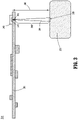
FIG. 2A is a cross-sectional view of a temperature measurement assembly in a handpiece of a surgical instrument in accordance with the present disclosure; -
FIG. 2B is an enlarged cross-sectional view of area "A" ofFIG. 2A ; and -
FIG. 3 is a layout view of the temperature measurement assembly ofFIG. 2A . - Descriptions of technical features or aspects of an exemplary configuration of the disclosure should typically be considered as available and applicable to other similar features or aspects in another exemplary configuration of the disclosure. Accordingly, technical features described herein according to one exemplary configuration of the disclosure may be applicable to other exemplary configurations of the disclosure, and thus duplicative descriptions may be omitted herein.
- Exemplary configurations of the disclosure will be described more fully below (e.g., with reference to the accompanying drawings). Like reference numerals may refer to like elements throughout the specification and drawings.
- Referring to
FIG. 1 , a surgical system provided in accordance with aspects of the present disclosure is shown generally identified byreference numeral 100.Surgical system 100 includes asurgical instrument 110, acontrol console 130, and acollection vessel 150.Surgical system 100 further includes acable 170,outflow tubing 180, andvacuum tubing 190.Surgical system 100 may further include an endoscope (not shown), e.g., a hysteroscope, defining a working channel for inserting ofsurgical instrument 110 therethrough, and adapted to connect to inflow tubing (not shown) to supply fluid to an internal surgical site and/or additional outflow tubing (not shown) to return fluid tocollection vessel 150. -
Surgical instrument 110 includes ahandpiece 112 that may be configured as a reusable component and anend effector assembly 114 that may be configured as a single-use, disposable component.Handpiece 112 includes ahousing 116 to facilitate grasping and manipulation ofsurgical instrument 110 by a user.Handpiece 112 further includes anoutput coupler 118 configured to operably engageend effector assembly 114, amotor 120 disposed withinhousing 116 and operably coupled tooutput coupler 118 to driveoutput coupler 118 and, thus, driveend effector assembly 114.Cable 170 electricallycouples handpiece 112 andcontrol console 130 with one another and, more specifically, electricallycouples control console 130 withmotor 120 to power and control operation ofmotor 120 and electricallycouples control console 130 with a storage device(s), e.g., a microchip(s) (not explicitly shown), associated withhandpiece 112 and/orend effector assembly 114 to enable communication of, for example, identification, setting, and control information therebetween. In embodiments,cable 170 is fixedly attached tohandpiece 112 and releasably couplable withcontrol console 130, although other configurations are also contemplated. - Continuing with reference to
FIG. 1 ,end effector assembly 114 includes aproximal hub 124 configured to releasably engagehousing 116 ofhandpiece 112 to releasably mechanically engageend effector assembly 114 withhandpiece 112.End effector assembly 114 further includes anouter shaft 126 extending distally fromproximal hub 124 and acutting shaft 128 extending throughouter shaft 126. A proximal end ofcutting shaft 128 extends intoproximal hub 124 wherein aninput coupler 129 is engaged withcutting shaft 128.Input coupler 129 is configured to operably couple tooutput coupler 118 ofhandpiece 112 whenproximal hub 124 is engaged withhousing 116 such that, whenmotor 120 is activated to driveoutput coupler 118,input coupler 129 is driven in a corresponding manner to thereby movecutting shaft 128 within and relative toouter shaft 126. -
Outer shaft 126, as noted above, extends distally fromproximal hub 124 and, in embodiments, is stationary relative toproximal hub 124, although other configurations are also contemplated.Outer shaft 126 may define a window (not shown) through a side wall thereof towards a distal end thereof to provide access to cuttingshaft 128 which is rotatably and/or translatably disposed withinouter shaft 126.Cutting shaft 128 may define an opening (not shown) towards the distal end thereof providing access to the interior thereof and may include a serrated cutting edge (not shown) surrounding the opening, although other suitable cutting-edge configurations are also contemplated. Alternatively, or additionally,outer shaft 126 may include a cutting edge defined about the window thereof. -
Motor 120, as noted above, is activated to movecutting shaft 128 and, more specifically, to drive rotation and/or translation ofcutting shaft 128 relative toouter shaft 126.Control console 130, coupled tomotor 120 viacable 170, enables selective powering and controlling ofmotor 120 and, thus, selective rotation and/or translation of cuttingshaft 128 relative toouter shaft 126 to resect tissue adjacent the distal end ofend effector assembly 114.Control console 130 is detailed below. -
Outflow tubing 180 includes adistal end 184 configured to releasably couple to handpiece 112 and aproximal end 186 configured to couple tocollection vessel 150. More specifically,handpiece 112 defines an internal passage (not shown) that couplesdistal end 184 ofoutflow tubing 180 with the interior of cuttingshaft 128 in fluid communication with the interior of cuttingshaft 128 such that fluid, tissue, and debris drawn into cuttingshaft 128 and/orouter shaft 126 may be suctioned, under vacuum, e.g., fromvacuum pump 139 ofcontrol console 130, throughend effector assembly 114,handpiece 112, andoutflow tubing 180 tocollection vessel 150. - Referring still to
FIG. 1 ,collection vessel 150, as noted above, is coupled toproximal end 186 ofoutflow tubing 180 to receive the fluid, tissue, and debris suctioned throughend effector assembly 114 andoutflow tubing 180.Vacuum tubing 190 is coupled betweencollection vessel 150 and a vacuum source, e.g.,vacuum pump 139 ofcontrol console 130, such that, upon activation ofvacuum pump 139, negative pressure is established throughcollection vessel 150,outflow tubing 180, and the interior of cuttingshaft 128 ofend effector assembly 114 to draw the fluids, tissue, and debris into and through cuttingshaft 128,handpiece 112,outflow tubing 180, and intocollection vessel 150. -
Control console 130 generally includes anouter housing 132, a touch-screen display 134 accessible from the exterior ofouter housing 132, acable port 136 configured to receivecable 170, avacuum tubing port 138 configured to receivevacuum tubing 190, and avacuum pump 139 disposed withinouter housing 132 and operably coupled withvacuum port 138.Outer housing 132 further houses internal electronics (not shown) ofcontrol console 130.Control console 130 may be configured to connect to a mains power supply (not shown) for poweringcontrol console 130. Further,control console 130 may be configured to receive user input, e.g., use information, setting selections, etc., via touch-screen display 134 or a peripheral input device (not shown) coupled to controlconsole 130. Operational input, e.g., ON/OFF signals, power level settings (HI power vs. LO power), etc., may likewise be input via touch-screen display 134 or a peripheral input device (not shown) such as, for example, a footswitch (not shown), a handswitch (see, e.g.,handswitches FIG. 2A ) disposed onhandpiece 112, etc. - In use, upon an activation input provided to control
console 130,control console 130 powers and controls motor 120 ofhandpiece 112 to, in turn, drive cuttingshaft 128 ofend effector assembly 114 to resect tissue adjacent the distal end ofend effector assembly 114, whilevacuum pump 139 ofcontrol console 130 suctions fluid, the resected tissue, and debris through cuttingshaft 128,handpiece 112,outflow tubing 180, and intocollection vessel 150. - Referring to
FIGS. 2A, 2B , and3 , a surgical instrument provided in accordance with aspects of the present disclosure is shown generally identified byreference numeral 200.Surgical instrument 200 includes ahandpiece 212 including ahousing 216 and amotor 220 disposed in thehousing 216. Unless otherwise indicate herein, themotor 220 is substantially the same as themotor 120, thehandpiece 212 is substantially the same as thehandpiece 112, and thehousing 216 is substantially the same as thehousing 116. An end effector assembly (see, e.g.,end effector assembly 114 ofFIG. 1 ) is operably coupled to thehandpiece 212. Themotor 220 actuates the end effector assembly. - The
temperature measurement assembly 240 described below with reference toFIGS 2A, 2B , and3 may be positioned in thehandpiece 112 ofFIG. 1 . For example, the infrared (IR)sensor 243 may be employed to measure a temperature of themotor 120 and/or theoutput coupler 118 inhousing 116 ofhandle 112. - A
temperature measurement assembly 240 is in thehousing 216. Thetemperature measurement assembly 240 may include a digital thermophile temperature sensor or spot pyrometer. Thetemperature measurement assembly 240 measures a surface temperature of a component (see, e.g.,component 251 inFIG. 3 ) within thehousing 216 through anair gap 248 or atransparent spacer 249. Thus, thetemperature measurement assembly 240 may be employed to measure surface temperatures withinhousing 216 ofhandpiece 212 without the use of a wired temperature sensor, provided that a clear path for an IR beam is available to the desired surface. Thetemperature measurement assembly 240 can measure a temperature of themotor 220. For example, a surface temperature of anouter housing 247 of themotor 220 can be measured. - The
temperature measurement assembly 240 includes a printed circuit board (PCB) 241 including anorifice 242 extending through thePCB 241. An infrared (IR)sensor 243 is on thePCB 241. TheIR sensor 243 transmits IR light 244 to a temperature measurement location 245 (e.g., atemperature measurement location 245 on theouter housing 247 of the motor 220) through theorifice 242 of thePCB 241. Theorifice 242 provides an unobstructed optical path from theIR sensor 243 to thetemperature measurement location 245. Theorifice 242 may be filled with air or with a substantially transparent (to IR light) material such as transparent silicone. TheIR sensor 243 detects IR light 244 reflected from thetemperature measurement location 245 and back to theIR sensor 243 through theorifice 242 to determine a temperature of the temperature measurement location 245 (e.g., thetemperature measurement location 245 on theouter housing 247 of the motor 220). - In an aspect of the present disclosure, the
IR sensor 243 includes anIR filter 246. TheIR sensor 243 transmits the IR light 244 through theIR filter 246. TheIR filter 246 is on thePCB 241 and extends across theorifice 242 of thePCB 241. TheIR filter 246 may be disposed directly on thePCB 241. TheIR filter 246 is configured to selectively pass or block IR light and/or visible light based on the configuration of theIR sensor 243. Thus, theIR filter 246 may increase the sensitivity and accuracy of theIR sensor 243. - In an aspect of the present disclosure, the
IR sensor 243 is positioned to transmit IR light 244 acrossair gap 248 between thePCB 241 and thetemperature measurement location 245. - In an aspect of the present disclosure, a substantially
transparent spacer 249 is positioned between thePCB 241 and thetemperature measurement location 245. The substantiallytransparent spacer 249 may be formed of or may include silicone, such as transparent silicone. - As an example, the substantially
transparent spacer 249 may be disposed on themotor 220, such as on theouter housing 247 of themotor 220. TheIR sensor 243 transmits the IR light 244 across the substantiallytransparent spacer 249 to the temperature measurement location 245 (e.g., to thetemperature measurement location 245 of the motor 220). - The
IR sensor 243 may detect asurface temperature 245 at agap distance 250 of up to 1 meter, and thus theair gap 248 or thetransparent spacer 249 may each span a distance of up to 1 meter between theIR sensor 243 and thetemperature measurement location 245. - In an aspect of the present disclosure, an
output coupler 218 is operably coupled to themotor 220, and theIR sensor 243 transmits IR light 244 to atemperature measurement location 245 of theoutput coupler 218 to determine a surface temperature of thetemperature measurement location 245 of theoutput coupler 218. - Referring particularly to
FIG. 3 ,component 251 may be disposed inhandpiece 212.Component 251 may be a component of the handpiece other than themotor 220 or theoutput coupler 218. Thus, thetemperature measurement assembly 240 may be employed to measure a surface temperature of any component inhandpiece 212 that is accessible through an air gap (e.g., air gap 248) or through an optically transparent pathway (e.g., through transparent spacer 249) between thetemperature measurement assembly 240 and thecomponent 251 across agap distance 250. - It will be understood that various modifications may be made to the aspects and features disclosed herein. Therefore, the above description should not be construed as limiting, but merely as exemplifications of various aspects and features. Those skilled in the art will envision other modifications within the scope and spirit of the claims appended thereto. Further disclosed herein is the subject-matter of the following clauses:
- 1. A surgical instrument, comprising:
- a handpiece including a housing and a motor disposed in the housing;
- an end effector assembly operably coupled to the handpiece, wherein the motor is configured to actuate the end effector assembly; and
- a temperature measurement assembly disposed in the housing, the temperature measurement assembly configured to measure a temperature of the motor, the temperature measurement assembly including:
- a printed circuit board (PCB) including at least one orifice extending through the PCB; and
- an infrared (IR) sensor disposed on the PCB, the IR sensor configured to transmit IR light to a temperature measurement location of the motor through the at least one orifice of the PCB, and the IR sensor configured to detect IR light reflected from the temperature measurement location of the motor to determine a temperature of the temperature measurement location of the motor.
- 2. The surgical instrument of clause 1, wherein the IR sensor further includes an IR filter, and wherein the IR sensor transmits the IR light through the IR filter.
- 3. The surgical instrument of clause 2, wherein the IR filter is disposed on the PCB and extends across the at least one orifice of the PCB.
- 4. The surgical instrument of clause 1 or any of the preceding clauses, wherein the temperature measurement location of the motor is on an outer housing of the motor.
- 5. The surgical instrument of clause 1 or any of the preceding clauses, wherein the IR sensor is positioned to transmit IR light across an air gap between the PCB and the temperature measurement location of the motor.
- 6. The surgical instrument of clause 1 or any of the preceding clauses, further including a substantially transparent spacer between the PCB and the motor, wherein the IR sensor transmits the IR light across the transparent spacer to the temperature measurement location of the motor.
- 7. The surgical instrument of clause 6, wherein the substantially transparent spacer is formed of silicone.
- 8. A surgical instrument, comprising:
- a handpiece including a housing and a motor disposed in the housing;
- an output coupler operably coupled to the motor and extending from the housing;
- an end effector assembly operably coupled to the output coupler, wherein the motor is configured to drive the output coupler to actuate the end effector assembly; and
- a temperature measurement assembly disposed in the housing, the temperature measurement assembly configured to measure a temperature of the output coupler, the temperature measurement assembly including:
- a printed circuit board (PCB) including at least one orifice extending through the PCB; and
- an infrared (IR) sensor disposed on the PCB, the IR sensor configured to transmit IR light to a temperature measurement location of the output coupler through the at least one orifice of the PCB, and the IR sensor configured to detect IR light reflected from the temperature measurement location of the output coupler to determine a temperature of the temperature measurement location of the output coupler.
- 9. The surgical instrument of clause 8, wherein the IR sensor further includes an IR filter, and wherein the IR sensor transmits the IR light through the IR filter.
- 10. The surgical instrument of clause 9, wherein the IR filter is disposed on the PCB and extends across the at least one orifice of the PCB.
- 11. The surgical instrument of clause 8 or any of clauses 8-10, wherein the temperature measurement location of the output coupler is on an outer surface of the output coupler.
- 12. The surgical instrument of clause 8 or any of clauses 8-11, wherein the IR sensor is positioned to transmit IR light across an air gap between the PCB and the temperature measurement location of the output coupler.
- 13. The surgical instrument of clause 8 or any of clauses 8-12, further including a substantially transparent spacer between the PCB and the output coupler, wherein the IR sensor transmits the IR light across the transparent spacer to the temperature measurement location of the output coupler.
- 14. The surgical instrument of clause 13, wherein the substantially transparent spacer is formed of silicone.
Claims (14)
- A surgical instrument, comprising:a handpiece including a housing and a motor disposed in the housing;an end effector assembly operably coupled to the handpiece, wherein the motor is configured to actuate the end effector assembly; anda temperature measurement assembly disposed in the housing, the temperature measurement assembly configured to measure a temperature of the motor, the temperature measurement assembly including:a printed circuit board (PCB) including at least one orifice extending through the PCB; andan infrared (IR) sensor disposed on the PCB, the IR sensor configured to transmit IR light to a temperature measurement location of the motor through the at least one orifice of the PCB, and the IR sensor configured to detect IR light reflected from the temperature measurement location of the motor to determine a temperature of the temperature measurement location of the motor.
- The surgical instrument of claim 1, wherein the IR sensor further includes an IR filter, and wherein the IR sensor transmits the IR light through the IR filter.
- The surgical instrument of claim 2, wherein the IR filter is disposed on the PCB and extends across the at least one orifice of the PCB.
- The surgical instrument of any of the preceding claims, wherein the temperature measurement location of the motor is on an outer housing of the motor.
- The surgical instrument of any of the preceding claims, wherein the IR sensor is positioned to transmit IR light across an air gap between the PCB and the temperature measurement location of the motor.
- The surgical instrument of any of the preceding claims, further including a substantially transparent spacer between the PCB and the motor, wherein the IR sensor transmits the IR light across the transparent spacer to the temperature measurement location of the motor.
- The surgical instrument of claim 6, wherein the substantially transparent spacer is formed of silicone.
- A surgical instrument, comprising:a handpiece including a housing and a motor disposed in the housing;an output coupler operably coupled to the motor and extending from the housing;an end effector assembly operably coupled to the output coupler, wherein the motor is configured to drive the output coupler to actuate the end effector assembly; anda temperature measurement assembly disposed in the housing, the temperature measurement assembly configured to measure a temperature of the output coupler, the temperature measurement assembly including:a printed circuit board (PCB) including at least one orifice extending through the PCB; andan infrared (IR) sensor disposed on the PCB, the IR sensor configured to transmit IR light to a temperature measurement location of the output coupler through the at least one orifice of the PCB, and the IR sensor configured to detect IR light reflected from the temperature measurement location of the output coupler to determine a temperature of the temperature measurement location of the output coupler.
- The surgical instrument of claim 8, wherein the IR sensor further includes an IR filter, and wherein the IR sensor transmits the IR light through the IR filter.
- The surgical instrument of claim 9, wherein the IR filter is disposed on the PCB and extends across the at least one orifice of the PCB.
- The surgical instrument of any of claims 8-10, wherein the temperature measurement location of the output coupler is on an outer surface of the output coupler.
- The surgical instrument of any of claims 8-11, wherein the IR sensor is positioned to transmit IR light across an air gap between the PCB and the temperature measurement location of the output coupler.
- The surgical instrument of any of claims 8-12, further including a substantially transparent spacer between the PCB and the output coupler, wherein the IR sensor transmits the IR light across the transparent spacer to the temperature measurement location of the output coupler.
- The surgical instrument of claim 13, wherein the substantially transparent spacer is formed of silicone.
Applications Claiming Priority (2)
| Application Number | Priority Date | Filing Date | Title |
|---|---|---|---|
| US202063088562P | 2020-10-07 | 2020-10-07 | |
| US17/471,665 US12156673B2 (en) | 2020-10-07 | 2021-09-10 | Temperature measurement device for a handpiece of a surgical instrument |
Publications (1)
| Publication Number | Publication Date |
|---|---|
| EP3981338A1 true EP3981338A1 (en) | 2022-04-13 |
Family
ID=78211852
Family Applications (1)
| Application Number | Title | Priority Date | Filing Date |
|---|---|---|---|
| EP21200097.0A Withdrawn EP3981338A1 (en) | 2020-10-07 | 2021-09-30 | Temperature measurement device for a handpiece of a surgical instrument |
Country Status (2)
| Country | Link |
|---|---|
| US (1) | US12156673B2 (en) |
| EP (1) | EP3981338A1 (en) |
Citations (4)
| Publication number | Priority date | Publication date | Assignee | Title |
|---|---|---|---|---|
| EP2524667A2 (en) * | 2011-05-19 | 2012-11-21 | W & H Dentalwerk Bürmoos GmbH | Medical, in particular dental, handpiece with a temperature measuring device |
| EP2939607A1 (en) * | 2014-04-28 | 2015-11-04 | Covidien LP | Systems and methods for determining an end of life state for surgical devices |
| US20190254506A1 (en) * | 2018-02-22 | 2019-08-22 | Canon U.S.A., Inc. | Apparatus, method, and system to control torque |
| US10420554B2 (en) * | 2015-12-22 | 2019-09-24 | Covidien Lp | Personalization of powered surgical devices |
Family Cites Families (290)
| Publication number | Priority date | Publication date | Assignee | Title |
|---|---|---|---|---|
| US1585934A (en) | 1923-12-29 | 1926-05-25 | Radium Emanation Corp | Diagnostic needle |
| US1831786A (en) | 1926-04-20 | 1931-11-10 | California Packing Corp | Fruit peeling apparatus |
| US1666332A (en) | 1927-05-23 | 1928-04-17 | Edwin W Hirsch | Bladder-pressure-testing apparatus |
| US2708437A (en) | 1952-03-31 | 1955-05-17 | Elizabeth Painter Hutchins | Surgical instrument |
| US3297022A (en) | 1963-09-27 | 1967-01-10 | American Cystoscope Makers Inc | Endoscope |
| GB1288091A (en) | 1969-01-03 | 1972-09-06 | ||
| DE7107645U (en) | 1971-03-02 | 1971-05-27 | Storz K | ENDOSCOPE IN PARTICULAR CYSTOSCOPE |
| US3734099A (en) | 1971-04-07 | 1973-05-22 | H Bender | Powered surgical cutter |
| US3812855A (en) | 1971-12-15 | 1974-05-28 | Surgical Design Corp | System for controlling fluid and suction pressure |
| US3945375A (en) | 1972-04-04 | 1976-03-23 | Surgical Design Corporation | Rotatable surgical instrument |
| US3850162A (en) | 1972-07-03 | 1974-11-26 | J Iglesias | Endoscope with continuous irrigation |
| US3835842A (en) | 1972-07-03 | 1974-09-17 | J Iglesias | Endoscope with continuous irrigation |
| US3996921A (en) | 1975-04-17 | 1976-12-14 | Pharmacia Inc. | Method and apparatus for endoscopy |
| US4011869A (en) | 1975-08-01 | 1977-03-15 | David Kopf Instruments | Tubular cutting instrument |
| US3995619A (en) | 1975-10-14 | 1976-12-07 | Glatzer Stephen G | Combination subcutaneous suture remover, biopsy sampler and syringe |
| US3980252A (en) | 1975-10-31 | 1976-09-14 | John T. Hepburn Limited | Wire rope spooling mechanism |
| US4146405A (en) | 1977-01-19 | 1979-03-27 | Henry Timmer | Unitary dishwasher |
| US4108182A (en) | 1977-02-16 | 1978-08-22 | Concept Inc. | Reciprocation vitreous suction cutter head |
| US4198958A (en) | 1977-06-01 | 1980-04-22 | Olympus Optical Co., Ltd. | Flexible cap and instrument seal for a suction control device in an endoscope |
| US4414962A (en) | 1977-06-15 | 1983-11-15 | Carson Robert W | Operating arthroscope |
| US4203444A (en) | 1977-11-07 | 1980-05-20 | Dyonics, Inc. | Surgical instrument suitable for closed surgery such as of the knee |
| FR2415451A1 (en) | 1978-01-26 | 1979-08-24 | Bernard Parent | PANORAMIC VISION DIAGNOSTIC HYSTEROSCOPE |
| US4246902A (en) | 1978-03-10 | 1981-01-27 | Miguel Martinez | Surgical cutting instrument |
| US4210146A (en) | 1978-06-01 | 1980-07-01 | Anton Banko | Surgical instrument with flexible blade |
| US4316465A (en) | 1979-03-30 | 1982-02-23 | Dotson Robert S Jun | Ophthalmic handpiece with pneumatically operated cutter |
| US4294234A (en) | 1979-06-22 | 1981-10-13 | Olympus Optical Co., Ltd. | Endoscope |
| US4247180A (en) | 1979-08-06 | 1981-01-27 | Polaroid Corporation | Card motion picture apparatus with adjustable barrel cam |
| US4261346A (en) | 1979-11-23 | 1981-04-14 | Richard Wolf Medical Instruments Corporation | Endoscopes |
| DE2949278C2 (en) | 1979-12-07 | 1982-05-27 | Rainer Dipl.-Ing. 8261 Neuötting Kortländer | Device for knife conization of the cervix |
| US4369768A (en) | 1980-07-30 | 1983-01-25 | Marko Vukovic | Arthroscope |
| US4493698A (en) | 1980-11-03 | 1985-01-15 | Cooper Medical Devices | Method of performing opthalmic surgery utilizing a linear intra-ocular suction device |
| US4392485A (en) | 1981-02-17 | 1983-07-12 | Richard Wolf Gmbh | Endoscope |
| GB2093353B (en) | 1981-02-25 | 1984-09-19 | Dyonics Inc | A surgical instrument for arthroscopic arthroplasty |
| US4517977A (en) | 1981-07-24 | 1985-05-21 | Unisearch Limited | Co-axial tube surgical infusion/suction cutter tip |
| US4449538A (en) | 1982-01-25 | 1984-05-22 | John Corbitt | Medical-electronic body fluid accounting system |
| DE3206381C2 (en) | 1982-02-22 | 1986-07-10 | Olympus Winter & Ibe GmbH, 2000 Hamburg | Percutaneous nephroscope |
| DE3364922D1 (en) | 1982-05-28 | 1986-09-04 | Rhp Group Plc | Devices for converting rotary movement into linear movement |
| IL66047A0 (en) | 1982-06-13 | 1982-09-30 | Univ Ben Gurion | Method and device for measuring intrauterine pressure during labour |
| US5435805A (en) | 1992-08-12 | 1995-07-25 | Vidamed, Inc. | Medical probe device with optical viewing capability |
| US5421819A (en) | 1992-08-12 | 1995-06-06 | Vidamed, Inc. | Medical probe device |
| GR70998B (en) | 1982-11-03 | 1983-03-30 | Kollia Nik Georgio | |
| JPS59200644A (en) | 1983-04-27 | 1984-11-14 | オリンパス光学工業株式会社 | Surgical incision instrument |
| US4606330A (en) | 1983-08-09 | 1986-08-19 | Richard Wolf Gmbh | Device for disintegrating stones in bodily cavities or ducts |
| US4601290A (en) | 1983-10-11 | 1986-07-22 | Cabot Medical Corporation | Surgical instrument for cutting body tissue from a body area having a restricted space |
| DE3569876D1 (en) | 1984-02-20 | 1989-06-08 | Olympus Optical Co | Endoscopic ovum picker instruments |
| JPS60243625A (en) | 1984-05-18 | 1985-12-03 | Fuji Photo Optical Co Ltd | Connecting system of endoscope |
| GB2159419B (en) | 1984-05-29 | 1987-09-23 | Wolf Gmbh Richard | Uretero-renoscope |
| DE3443337A1 (en) | 1984-11-28 | 1986-05-28 | Richard Wolf Gmbh, 7134 Knittlingen | INSTRUMENT FOR THE EXAMINATION AND TREATMENT OF BODY CHANNELS |
| US4567880A (en) | 1984-12-26 | 1986-02-04 | Goodman Tobias M | Endoscopic device with three-way valve |
| US4971034A (en) | 1985-01-16 | 1990-11-20 | Asahi Kogaku Kogyo Kabushiki Kaisha | Body cavity pressure adjusting device for endoscope and laser medical treatment apparatus including body cavity pressure adjusting device |
| US4649919A (en) | 1985-01-23 | 1987-03-17 | Precision Surgical Instruments, Inc. | Surgical instrument |
| US4756309A (en) | 1985-02-14 | 1988-07-12 | Sachse Hans Ernst | Endoscope for removal of tissue |
| US4644952A (en) | 1985-02-19 | 1987-02-24 | Palm Beach Medical Engineering, Inc. | Surgical operating instrument |
| DE3601453A1 (en) | 1985-02-25 | 1986-09-04 | Hans E. Prof. Dr.Med. Sachse | Endoscope for the removal of tissue |
| JPS61259637A (en) | 1985-05-15 | 1986-11-17 | オリンパス光学工業株式会社 | Endoscope apparatus |
| JPS62105698A (en) | 1985-11-05 | 1987-05-16 | ソニー株式会社 | Printer |
| DE3615694A1 (en) | 1986-05-09 | 1987-11-12 | Winter & Ibe Olympus | Percutaneous nephroscope with safety wire |
| US4950278A (en) | 1986-08-06 | 1990-08-21 | Sachse Hans E | Endoscope for removal of tissue |
| US4749376A (en) | 1986-10-24 | 1988-06-07 | Intravascular Surgical Instruments, Inc. | Reciprocating working head catheter |
| US5312430A (en) | 1986-12-09 | 1994-05-17 | Rosenbluth Robert F | Balloon dilation catheter |
| US4867157A (en) | 1987-08-13 | 1989-09-19 | Baxter Travenol Laboratories, Inc. | Surgical cutting instrument |
| US4850354A (en) | 1987-08-13 | 1989-07-25 | Baxter Travenol Laboratories, Inc. | Surgical cutting instrument |
| US4819635A (en) | 1987-09-18 | 1989-04-11 | Henry Shapiro | Tubular microsurgery cutting apparatus |
| US4844064A (en) | 1987-09-30 | 1989-07-04 | Baxter Travenol Laboratories, Inc. | Surgical cutting instrument with end and side openings |
| US4986827A (en) | 1987-11-05 | 1991-01-22 | Nestle S.A. | Surgical cutting instrument with reciprocating inner cutter |
| FR2625428A1 (en) | 1988-01-05 | 1989-07-07 | Sinergy Sa | MULTIFUNCTIONAL OPERATIVE COELIOSCOPY DEVICE FOR PERFORMING DIFFERENT OPERATIVE GESTURES WITH INTRODUCTION OF INSTRUMENTS |
| DE3805368C1 (en) | 1988-02-17 | 1989-08-24 | Peter P. Dipl.-Ing. Wiest | |
| US4955882A (en) | 1988-03-30 | 1990-09-11 | Hakky Said I | Laser resectoscope with mechanical and laser cutting means |
| US5027792A (en) | 1989-03-17 | 1991-07-02 | Percutaneous Technologies, Inc. | Endoscopic revision hip surgery device |
| US5116868A (en) | 1989-05-03 | 1992-05-26 | The Johns Hopkins University | Effective ophthalmic irrigation solution |
| JP2787471B2 (en) | 1989-07-04 | 1998-08-20 | 旭光学工業株式会社 | Endoscope sheath device |
| US5226910A (en) | 1989-07-05 | 1993-07-13 | Kabushiki Kaisha Topcon | Surgical cutter |
| US5106364A (en) | 1989-07-07 | 1992-04-21 | Kabushiki Kaisha Topcon | Surgical cutter |
| US4998527A (en) | 1989-07-27 | 1991-03-12 | Percutaneous Technologies Inc. | Endoscopic abdominal, urological, and gynecological tissue removing device |
| US5226909A (en) | 1989-09-12 | 1993-07-13 | Devices For Vascular Intervention, Inc. | Atherectomy device having helical blade and blade guide |
| US5112299A (en) | 1989-10-25 | 1992-05-12 | Hall Surgical Division Of Zimmer, Inc. | Arthroscopic surgical apparatus and method |
| US5163433A (en) | 1989-11-01 | 1992-11-17 | Olympus Optical Co., Ltd. | Ultrasound type treatment apparatus |
| US5409013A (en) | 1989-11-06 | 1995-04-25 | Mectra Labs, Inc. | Tissue removal assembly |
| US5037386A (en) | 1989-11-17 | 1991-08-06 | Minnesota Mining And Manufacturing Company | Pressure sensing scope cannula |
| US5176677A (en) | 1989-11-17 | 1993-01-05 | Sonokinetics Group | Endoscopic ultrasonic rotary electro-cauterizing aspirator |
| US4940061A (en) | 1989-11-27 | 1990-07-10 | Ingress Technologies, Inc. | Biopsy instrument |
| US5152744A (en) | 1990-02-07 | 1992-10-06 | Smith & Nephew Dyonics | Surgical instrument |
| US5169397A (en) | 1990-02-08 | 1992-12-08 | Olympus Optical Co., Ltd. | Medical instrument |
| US5007917A (en) | 1990-03-08 | 1991-04-16 | Stryker Corporation | Single blade cutter for arthroscopic surgery |
| EP0448857A1 (en) | 1990-03-27 | 1991-10-02 | Jong-Khing Huang | An apparatus of a spinning type of resectoscope for prostatectomy |
| US5275609A (en) | 1990-06-22 | 1994-01-04 | Vance Products Incorporated | Surgical cutting instrument |
| US5269785A (en) | 1990-06-28 | 1993-12-14 | Bonutti Peter M | Apparatus and method for tissue removal |
| US5911699A (en) | 1990-07-17 | 1999-06-15 | Aziz Yehia Anis | Removal of tissue |
| US6007513A (en) | 1990-07-17 | 1999-12-28 | Aziz Yehia Anis | Removal of tissue |
| DE4038398A1 (en) | 1990-12-01 | 1992-06-04 | Schubert Werner | Medical equipment for min. invasive operation e.g. for removal of tumour - introduces knife on long handle through cylinder or tube adjusted into pathological tissue |
| US5158553A (en) | 1990-12-26 | 1992-10-27 | Cardiopulmonics | Rotatably actuated constricting catheter valve |
| EP0566694A1 (en) | 1991-01-09 | 1993-10-27 | EndoMedix Corporation | Method and device for intracorporeal liquidization of tissue and/or intracorporeal fragmentation of calculi during endoscopic surgical procedures |
| US5409453A (en) | 1992-08-12 | 1995-04-25 | Vidamed, Inc. | Steerable medical probe with stylets |
| US5125910A (en) | 1991-02-19 | 1992-06-30 | Dexide, Inc. | Surgical endoscopic suction/irrigation cannula assembly |
| US5586973A (en) | 1991-04-22 | 1996-12-24 | C & D Biomedical S.A. | Method and device for controlled irrigation and suctioning of a liquid clarificant during endoscopic surgery |
| US5490819A (en) | 1991-08-05 | 1996-02-13 | United States Surgical Corporation | Articulating endoscopic surgical apparatus |
| US5391180A (en) | 1991-08-05 | 1995-02-21 | United States Surgical Corporation | Articulating endoscopic surgical apparatus |
| EP0692266B1 (en) | 1991-08-21 | 2000-03-22 | Smith & Nephew, Inc. | Fluid management system |
| US5288290A (en) | 1991-09-25 | 1994-02-22 | Alcon Surgical, Inc. | Multi-ported valve assembly |
| US5195541A (en) | 1991-10-18 | 1993-03-23 | Obenchain Theodore G | Method of performing laparoscopic lumbar discectomy |
| US5449356A (en) | 1991-10-18 | 1995-09-12 | Birtcher Medical Systems, Inc. | Multifunctional probe for minimally invasive surgery |
| US5244459A (en) | 1992-01-28 | 1993-09-14 | Hill Raymond R | Suction irrigator endoscope |
| MX9300607A (en) | 1992-02-06 | 1993-10-01 | American Med Syst | APPARATUS AND METHOD FOR INTERSTITIAL TREATMENT. |
| US5242404A (en) | 1992-02-12 | 1993-09-07 | American Cyanamid Company | Aspiration control system |
| US5269798A (en) | 1992-02-19 | 1993-12-14 | Linvatec Corporation | Surgical cutting instrument with movable, inner and outer tubular members |
| US5254117A (en) | 1992-03-17 | 1993-10-19 | Alton Dean Medical | Multi-functional endoscopic probe apparatus |
| US5350390A (en) | 1992-03-25 | 1994-09-27 | Arieh Sher | Device for removal of intraluminal occlusions |
| US5563481A (en) | 1992-04-13 | 1996-10-08 | Smith & Nephew Endoscopy, Inc. | Brushless motor |
| US5672945A (en) | 1992-04-13 | 1997-09-30 | Smith & Nephew Endoscopy, Inc. | Motor controlled surgical system and method having self clearing motor control |
| US5602449A (en) | 1992-04-13 | 1997-02-11 | Smith & Nephew Endoscopy, Inc. | Motor controlled surgical system and method having positional control |
| US5270622A (en) | 1992-04-13 | 1993-12-14 | Smith & Nephew Dyonics, Inc. | Brushless motor control system |
| US5320091A (en) | 1992-04-27 | 1994-06-14 | Circon Corporation | Continuous flow hysteroscope |
| US5556378A (en) | 1992-06-17 | 1996-09-17 | Storz; Karl | Device for irrigation of body cavities |
| CA2101293C (en) | 1992-08-05 | 2004-06-29 | David A. Nicholas | Articulating endoscopic surgical apparatus |
| US5312399A (en) | 1992-09-29 | 1994-05-17 | Hakky Said I | Laser resectoscope with mechanical cutting means and laser coagulating means |
| SE501876C2 (en) | 1992-11-12 | 1995-06-12 | Christer Dahlstrand Ab | Motorised arrangement for endoscopic removal of prostate tissue - includes tubular body, with hand grip, channels for inspection, lighting, and input for flushing fluid for removal of fluid and cut-away tissue |
| US5304118A (en) | 1992-12-16 | 1994-04-19 | Trese Michael T | Method for performing a vitrectomy on an eye |
| US5347992A (en) | 1993-01-22 | 1994-09-20 | Karl Storz Endoscopy America, Inc. | Single axis three way selector valve for endoscopes |
| US5392765A (en) | 1993-02-11 | 1995-02-28 | Circon Corporation | Continuous flow cystoscope |
| US5403276A (en) | 1993-02-16 | 1995-04-04 | Danek Medical, Inc. | Apparatus for minimally invasive tissue removal |
| US5624590A (en) * | 1993-04-02 | 1997-04-29 | Lucent Technologies, Inc. | Semiconductor processing technique, including pyrometric measurement of radiantly heated bodies and an apparatus for practicing this technique |
| CA2121861A1 (en) | 1993-04-23 | 1994-10-24 | William D. Fox | Mechanical morcellator |
| CA2161688A1 (en) | 1993-05-07 | 1994-11-24 | Sdgi Holdings, Inc. | Surgical cutting instrument |
| US5364395A (en) | 1993-05-14 | 1994-11-15 | West Jr Hugh S | Arthroscopic surgical instrument with cauterizing capability |
| DE59400518D1 (en) | 1993-06-16 | 1996-09-26 | White Spot Ag | DEVICE FOR PUTTING FIBRINE ADHESIVE INTO A STITCH CHANNEL |
| US5395313A (en) | 1993-08-13 | 1995-03-07 | Naves; Neil H. | Reciprocating arthroscopic shaver |
| US5575756A (en) | 1993-08-16 | 1996-11-19 | Olympus Optical Co., Ltd. | Endoscope apparatus |
| US5336237A (en) | 1993-08-25 | 1994-08-09 | Devices For Vascular Intervention, Inc. | Removal of tissue from within a body cavity |
| US5425376A (en) | 1993-09-08 | 1995-06-20 | Sofamor Danek Properties, Inc. | Method and apparatus for obtaining a biopsy sample |
| US5957832A (en) | 1993-10-08 | 1999-09-28 | Heartport, Inc. | Stereoscopic percutaneous visualization system |
| US5374253A (en) | 1993-10-12 | 1994-12-20 | Burns, Sr.; Charles N. | Medical instrument with automatic shut-off valve |
| US5456689A (en) | 1993-10-13 | 1995-10-10 | Arnold J. Kresch | Method and device for tissue resection |
| WO1995010982A1 (en) | 1993-10-20 | 1995-04-27 | Correa Marco Aurelio Moura De | Surgical instrument to perform subcutaneous endoscopic surgery |
| US5443476A (en) | 1993-11-12 | 1995-08-22 | Shapiro; Henry | Microsurgical scissor apparatus with rotary cutting blade |
| DE4340056A1 (en) | 1993-11-24 | 1995-06-01 | Delma Elektro Med App | Laparoscopic surgical device |
| US5490860A (en) | 1993-12-08 | 1996-02-13 | Sofamor Danek Properties, Inc. | Portable power cutting tool |
| EP0662572B1 (en) | 1994-01-11 | 1998-04-01 | SAMJOO MACHINERY Co., Ltd. | Rotary motion/constant velocity linear reciprocating motion conversion device and hydraulic system using the same |
| US6359200B1 (en) | 1994-01-13 | 2002-03-19 | Dekalb Genetics Corp. | Inbred corn plant 8M116 |
| US5411513A (en) | 1994-02-24 | 1995-05-02 | Danek Medical, Inc. | Transmission mechanism for a surgical cutting instrument |
| US5483951A (en) | 1994-02-25 | 1996-01-16 | Vision-Sciences, Inc. | Working channels for a disposable sheath for an endoscope |
| US5456673A (en) | 1994-03-23 | 1995-10-10 | Stryker Corporation | Locking cannula for endoscopic surgery |
| US5526822A (en) | 1994-03-24 | 1996-06-18 | Biopsys Medical, Inc. | Method and apparatus for automated biopsy and collection of soft tissue |
| US5649547A (en) | 1994-03-24 | 1997-07-22 | Biopsys Medical, Inc. | Methods and devices for automated biopsy and collection of soft tissue |
| US5709670A (en) | 1994-05-03 | 1998-01-20 | Aquintel, Inc. | Surgical fluid and tissue loss monitor |
| US5492537A (en) | 1994-05-03 | 1996-02-20 | Aquintel, Inc. | Surgical fluid monitor |
| US5702420A (en) | 1994-06-14 | 1997-12-30 | Anthony R. Sterling And Tri-Tech, Inc. | Motorized suction punch forceps |
| US5669921A (en) | 1994-07-19 | 1997-09-23 | Linvatec Corporation | Endoscopic shaver blade window positioning system |
| JP2802244B2 (en) | 1994-08-29 | 1998-09-24 | オリンパス光学工業株式会社 | Endoscope sheath |
| US5498258A (en) | 1994-09-13 | 1996-03-12 | Hakky; Said I. | Laser resectoscope with laser induced mechanical cutting means |
| US5569284A (en) | 1994-09-23 | 1996-10-29 | United States Surgical Corporation | Morcellator |
| WO1997017027A1 (en) | 1995-11-08 | 1997-05-15 | Femrx, Inc. | Electrosurgical device having rollers for ablating and segmenting of tissues |
| US6032673A (en) | 1994-10-13 | 2000-03-07 | Femrx, Inc. | Methods and devices for tissue removal |
| WO1996011638A1 (en) | 1994-10-13 | 1996-04-25 | Femrx | Method and device for tissue resection |
| WO1996012453A1 (en) | 1994-10-24 | 1996-05-02 | Smith & Nephew Inc. | Hollow surgical cutter with apertured flutes |
| DE4440035C2 (en) | 1994-11-10 | 1998-08-06 | Wolf Gmbh Richard | Morcellating instrument |
| US5603332A (en) | 1995-01-27 | 1997-02-18 | Technological Services, Inc. | Method and apparatus for monitoring the systemic absorption of irrigation fluid during operative hysteroscopy |
| US5601583A (en) | 1995-02-15 | 1997-02-11 | Smith & Nephew Endoscopy Inc. | Surgical instrument |
| US5676497A (en) | 1995-02-27 | 1997-10-14 | Kim; Young S. | Power drill-saw with simultaneous rotation and reciprocation action |
| DE29503478U1 (en) | 1995-03-02 | 1995-04-20 | Richard Wolf Gmbh, 75438 Knittlingen | endoscope |
| US5810861A (en) | 1995-03-02 | 1998-09-22 | Gaber; Benny | Uterine tissue collector |
| ATE270854T1 (en) | 1995-03-31 | 2004-07-15 | Boston Scient Ltd | BIOPSY SAMPLER |
| US5873886A (en) | 1995-04-04 | 1999-02-23 | United States Surgical Corporation | Surgical cutting apparatus |
| US5569254A (en) | 1995-04-12 | 1996-10-29 | Midas Rex Pneumatic Tools, Inc. | Surgical resection tool having an irrigation, lighting, suction and vision attachment |
| US5591187A (en) | 1995-07-14 | 1997-01-07 | Dekel; Moshe | Laparoscopic tissue retrieval device and method |
| AUPN541595A0 (en) | 1995-09-13 | 1995-10-12 | Queensland University Of Technology | A surgical device |
| US5749885A (en) | 1995-10-02 | 1998-05-12 | Smith & Nephew, Inc. | Surgical instrument with embedded coding element |
| US5772634A (en) | 1995-10-06 | 1998-06-30 | Zimmer, Inc. | Device for limiting distention fluid pressure during hysteroscopy |
| DE19633124B4 (en) | 1995-11-20 | 2009-06-10 | Storz Endoskop Gmbh | Scraping or cutting instrument |
| PT805652E (en) | 1995-11-27 | 2003-02-28 | C C D Lab | DEVICE FOR THE COLLECTION OF UTERINE MUCOSES |
| US5807282A (en) | 1995-12-28 | 1998-09-15 | Mayo Foundation For Medical Education And Research | Endometrial tissue curette and method |
| US5916229A (en) | 1996-02-07 | 1999-06-29 | Evans; Donald | Rotating needle biopsy device and method |
| US5749889A (en) | 1996-02-13 | 1998-05-12 | Imagyn Medical, Inc. | Method and apparatus for performing biopsy |
| US5709698A (en) | 1996-02-26 | 1998-01-20 | Linvatec Corporation | Irrigating/aspirating shaver blade assembly |
| WO1997034534A1 (en) | 1996-03-18 | 1997-09-25 | Femrx, Inc. | Method and device for tissue vaporization and extraction |
| DE69725005T2 (en) | 1996-03-25 | 2004-06-17 | Safe Conduct Ab | DEVICE FOR TAKING TISSUE OR THE LIKE |
| DE19706751A1 (en) | 1996-03-27 | 1997-10-02 | Valleylab Inc | Electrosurgical device for removing tissue in body areas |
| US5766199A (en) | 1996-04-10 | 1998-06-16 | Linvatec Corporation | Endoscopic shaver blade with resilient cutting edges |
| BE1010290A3 (en) | 1996-05-10 | 1998-05-05 | Saturnus Ag | TISSUE-morcellator. |
| US5833643A (en) | 1996-06-07 | 1998-11-10 | Scieran Technologies, Inc. | Apparatus for performing ophthalmic procedures |
| US6258111B1 (en) | 1997-10-03 | 2001-07-10 | Scieran Technologies, Inc. | Apparatus and method for performing ophthalmic procedures |
| US5741286A (en) | 1996-06-07 | 1998-04-21 | Symbiosis Corporation | Laparoscopic instrument kit including a plurality of rigid tubes |
| US6113594A (en) | 1996-07-02 | 2000-09-05 | Ethicon, Inc. | Systems, methods and apparatus for performing resection/ablation in a conductive medium |
| US6017354A (en) | 1996-08-15 | 2000-01-25 | Stryker Corporation | Integrated system for powered surgical tools |
| US5857995A (en) | 1996-08-15 | 1999-01-12 | Surgical Dynamics, Inc. | Multiple bladed surgical cutting device removably connected to a rotary drive element |
| US5769794A (en) | 1996-09-04 | 1998-06-23 | Smith & Nephew Endoscopy, Inc | Tissue retrieval bag and method for removing cancerous tissue |
| SE509513C2 (en) | 1996-09-16 | 1999-02-08 | Endolink Ab | Tools for use in surgical procedures on the uterus and cervix |
| US5807240A (en) | 1996-09-24 | 1998-09-15 | Circon Corporation | Continuous flow endoscope with enlarged outflow channel |
| US6090094A (en) | 1996-10-04 | 2000-07-18 | Microgroup, Inc. | Ball valves and uses thereof including endoscopic surgical instruments |
| US5814009A (en) | 1996-10-11 | 1998-09-29 | Cabot Technology Corporation | Fluid management system and replaceable tubing assembly therefor |
| US5730752A (en) | 1996-10-29 | 1998-03-24 | Femrx, Inc. | Tubular surgical cutters having aspiration flow control ports |
| US5741287A (en) | 1996-11-01 | 1998-04-21 | Femrx, Inc. | Surgical tubular cutter having a tapering cutting chamber |
| US5899915A (en) | 1996-12-02 | 1999-05-04 | Angiotrax, Inc. | Apparatus and method for intraoperatively performing surgery |
| US5810770A (en) | 1996-12-13 | 1998-09-22 | Stryker Corporation | Fluid management pump system for surgical procedures |
| US5913867A (en) | 1996-12-23 | 1999-06-22 | Smith & Nephew, Inc. | Surgical instrument |
| US5947990A (en) | 1997-02-24 | 1999-09-07 | Smith & Nephew, Inc. | Endoscopic surgical instrument |
| US6024751A (en) | 1997-04-11 | 2000-02-15 | Coherent Inc. | Method and apparatus for transurethral resection of the prostate |
| US6156049A (en) | 1997-04-11 | 2000-12-05 | Coherent Inc. | Method and apparatus for transurethral resection of the prostate |
| US5925055A (en) | 1997-06-23 | 1999-07-20 | Medelex, Inc | Multimodal rotary abrasion and acoustic ablation catheter |
| US6086542A (en) | 1997-07-01 | 2000-07-11 | Linvatec Corporation | Pressure sensing input/output scope sheath |
| US6149633A (en) | 1997-07-15 | 2000-11-21 | Surgin Surgical Instrumentation, Inc. | Flow control system and method for endoscopic surgeries |
| JP2001510066A (en) | 1997-07-18 | 2001-07-31 | ガイラス・メディカル・リミテッド | Electrosurgical instrument |
| EP0996378B1 (en) | 1997-07-18 | 2004-06-30 | Gyrus Medical Limited | An electrosurgical instrument |
| US6039748A (en) | 1997-08-05 | 2000-03-21 | Femrx, Inc. | Disposable laparoscopic morcellator |
| NL1006944C2 (en) | 1997-09-04 | 1999-03-11 | Mark Hans Emanuel | Surgical endoscopic cutting device. |
| US6004320A (en) | 1997-09-19 | 1999-12-21 | Oratec Interventions, Inc. | Clip on electrocauterizing sheath for orthopedic shave devices |
| US6102895A (en) | 1997-09-30 | 2000-08-15 | Cortella; Julian M. | Digital fluid delivery and aspiration apparatus with mechanical de-amplifier |
| DE19751632C1 (en) | 1997-11-21 | 1999-09-16 | Aesculap Ag & Co Kg | Hysteroscope for examination of cervical canals |
| JP2002502626A (en) | 1998-02-10 | 2002-01-29 | アーテミス・メディカル・インコーポレイテッド | Supplementary device and method of using the same |
| US6659105B2 (en) | 1998-02-26 | 2003-12-09 | Senorx, Inc. | Tissue specimen isolating and damaging device and method |
| US6344026B1 (en) | 1998-04-08 | 2002-02-05 | Senorx, Inc. | Tissue specimen encapsulation device and method thereof |
| US6331166B1 (en) | 1998-03-03 | 2001-12-18 | Senorx, Inc. | Breast biopsy system and method |
| US6159160A (en) | 1998-03-26 | 2000-12-12 | Ethicon, Inc. | System and method for controlled infusion and pressure monitoring |
| US6156043A (en) | 1998-05-26 | 2000-12-05 | Krahn; Henry P. | Soft tissue morsellator |
| US6224603B1 (en) | 1998-06-09 | 2001-05-01 | Nuvasive, Inc. | Transiliac approach to entering a patient's intervertebral space |
| US6132448A (en) | 1998-06-19 | 2000-10-17 | Stryker Corporation | Endoscopic irrigated bur |
| US5911722A (en) | 1998-07-23 | 1999-06-15 | Millenium Devices Llc | Leban/Gordon surgical hand driver |
| US6068641A (en) | 1998-08-25 | 2000-05-30 | Linvatec Corporation | Irrigated burr |
| US6136014A (en) | 1998-09-01 | 2000-10-24 | Vivant Medical, Inc. | Percutaneous tissue removal device |
| US6245084B1 (en) | 1998-10-20 | 2001-06-12 | Promex, Inc. | System for controlling a motor driven surgical cutting instrument |
| US6494892B1 (en) | 1998-10-20 | 2002-12-17 | Suros Surgical Systems, Inc. | Disposable hub for a surgical cutting instrument |
| US6632182B1 (en) | 1998-10-23 | 2003-10-14 | The Trustees Of Columbia University In The City Of New York | Multiple bit, multiple specimen endoscopic biopsy forceps |
| JP3448228B2 (en) | 1998-11-30 | 2003-09-22 | 富士写真光機株式会社 | Endoscope insertion guide tube |
| US6244228B1 (en) | 1998-12-11 | 2001-06-12 | Damon Kuhn | Rotary-to-linear motion converter and use thereof |
| US6119973A (en) | 1999-01-29 | 2000-09-19 | Owens Corning Fiberglas Technology, Inc. | Reciprocating apparatus and cam follower for winding a package |
| EP1152684B1 (en) | 1999-02-18 | 2003-12-17 | Karl Storz GmbH & Co. KG | Endoscope |
| US20020165427A1 (en) | 1999-03-15 | 2002-11-07 | Daniel Yachia | Intravesicular device |
| US6120147A (en) | 1999-03-17 | 2000-09-19 | Dutch Ophthalmic Research Center International Bv | Vitrectomy lens |
| US6159209A (en) | 1999-03-18 | 2000-12-12 | Canox International Ltd. | Automatic resectoscope |
| US6402701B1 (en) | 1999-03-23 | 2002-06-11 | Fna Concepts, Llc | Biopsy needle instrument |
| US6066153A (en) | 1999-03-31 | 2000-05-23 | Lev; Avigdor | Device and method for resecting body tissues |
| US6120462A (en) | 1999-03-31 | 2000-09-19 | Ethicon Endo-Surgery, Inc. | Control method for an automated surgical biopsy device |
| US7128708B2 (en) | 2002-06-13 | 2006-10-31 | Usgi Medical Inc. | Shape lockable apparatus and method for advancing an instrument through unsupported anatomy |
| US6358200B1 (en) | 1999-09-01 | 2002-03-19 | Circon Corporation | Continuous flow resectoscope with single tube sheath assembly and rotatable connection |
| JP2001075416A (en) | 1999-09-03 | 2001-03-23 | Konica Corp | Image forming device |
| US6368324B1 (en) | 1999-09-24 | 2002-04-09 | Medtronic Xomed, Inc. | Powered surgical handpiece assemblies and handpiece adapter assemblies |
| SE9904223D0 (en) | 1999-11-19 | 1999-11-19 | Safe Conduct Ab | Working Device |
| JP2001149374A (en) | 1999-11-29 | 2001-06-05 | Asahi Optical Co Ltd | Endoscope tissue collection tool |
| WO2001058368A1 (en) | 2000-02-10 | 2001-08-16 | Harmonia Medical Technologies Inc. | Transurethral volume reduction of the prostate (tuvor) |
| JP4295459B2 (en) | 2000-02-18 | 2009-07-15 | ストライカー コーポレイション | Surgical instrument cutting accessories |
| US6626827B1 (en) | 2000-09-01 | 2003-09-30 | C. R. Bard, Inc. | Fluid management assembly for use in endoscopic procedures |
| AU2001270943A1 (en) | 2000-06-14 | 2001-12-24 | Harmonia Medical Technologies, INC | Surgical instrument and method of using the same |
| US6712773B1 (en) | 2000-09-11 | 2004-03-30 | Tyco Healthcare Group Lp | Biopsy system |
| WO2002069808A2 (en) | 2000-11-06 | 2002-09-12 | Suros Surgical Systems, Inc. | Biopsy apparatus |
| US20030050603A1 (en) | 2001-09-12 | 2003-03-13 | Todd Erik F. | Cannula that provides bi-directional fluid flow that is regulated by a single valve |
| US7510563B2 (en) | 2001-10-26 | 2009-03-31 | Smith & Nephew, Inc. | Reciprocating rotary arthroscopic surgical instrument |
| US7226459B2 (en) | 2001-10-26 | 2007-06-05 | Smith & Nephew, Inc. | Reciprocating rotary arthroscopic surgical instrument |
| DE10164384A1 (en) | 2001-12-28 | 2003-07-17 | Wolf Gmbh Richard | Hysteroscope with alternating shaft system |
| JP4056760B2 (en) | 2002-02-22 | 2008-03-05 | ペンタックス株式会社 | Endoscope suction switching mechanism |
| DE50301103D1 (en) | 2002-03-19 | 2005-10-06 | Bard Dublin Itc Ltd | VACUUM BIOPSY DEVICE |
| DE10310614B4 (en) | 2002-03-25 | 2007-10-11 | Richard Wolf Gmbh | resectoscope |
| EP1603462B1 (en) | 2003-02-25 | 2015-07-15 | Devicor Medical Products, Inc. | Biopsy device with variable speed cutter advance |
| US7150713B2 (en) | 2003-10-16 | 2006-12-19 | Smith & Nephew, Inc. | Endoscopic device |
| DE10358279A1 (en) | 2003-12-11 | 2005-07-14 | Karl Storz Gmbh & Co. Kg | Medical instrument for cutting biological and especially human tissue |
| US7500947B2 (en) | 2004-01-29 | 2009-03-10 | Cannonflow, Inc. | Atraumatic arthroscopic instrument sheath |
| US7413542B2 (en) | 2004-01-29 | 2008-08-19 | Cannuflow, Inc. | Atraumatic arthroscopic instrument sheath |
| US20050228417A1 (en) | 2004-03-26 | 2005-10-13 | Teitelbaum George P | Devices and methods for removing a matter from a body cavity of a patient |
| US8062214B2 (en) | 2004-08-27 | 2011-11-22 | Smith & Nephew, Inc. | Tissue resecting system |
| US20060251581A1 (en) | 2005-05-09 | 2006-11-09 | Mcintyre Jon T | Method for treatment of uterine fibroid tumors |
| US7806871B2 (en) | 2005-05-09 | 2010-10-05 | Boston Scientific Scimed, Inc. | Method and device for tissue removal and for delivery of a therapeutic agent or bulking agent |
| US8932208B2 (en) | 2005-05-26 | 2015-01-13 | Maquet Cardiovascular Llc | Apparatus and methods for performing minimally-invasive surgical procedures |
| DE202005008569U1 (en) | 2005-06-01 | 2005-09-08 | Polydiagnost Gmbh | Endoscopic instrument, comprising specifically arranged optical device, lighting device, and rinsing duct |
| KR101397210B1 (en) * | 2005-06-28 | 2014-05-21 | 스트리커 코포레이션 | Control assembly for a motorized surgical tool that contains a sensor that monitors the state of the motor rotor |
| US20070173736A1 (en) | 2005-10-07 | 2007-07-26 | Femspec Llc | Apparatus and methods for endometrial biopsies |
| WO2008033356A2 (en) | 2006-09-11 | 2008-03-20 | Karl Storz Endovision, Inc. | System and method for an hysteroscope with integrated instruments |
| US8840625B2 (en) | 2006-10-18 | 2014-09-23 | Hologic, Inc. | Systems for performing gynecological procedures with closed visualization lumen |
| US8025656B2 (en) | 2006-11-07 | 2011-09-27 | Hologic, Inc. | Methods, systems and devices for performing gynecological procedures |
| US9392935B2 (en) | 2006-11-07 | 2016-07-19 | Hologic, Inc. | Methods for performing a medical procedure |
| US20080262308A1 (en) | 2007-02-27 | 2008-10-23 | Percutaneaus Systems, Inc. | Method and system for performing continuous flow endoscopy |
| US20090270898A1 (en) | 2007-04-06 | 2009-10-29 | Interlace Medical, Inc. | Tissue removal device with high reciprocation rate |
| EP2134283B1 (en) | 2007-04-06 | 2014-06-11 | Hologic, Inc. | System and device for tissue removal |
| US9095366B2 (en) | 2007-04-06 | 2015-08-04 | Hologic, Inc. | Tissue cutter with differential hardness |
| US9259233B2 (en) | 2007-04-06 | 2016-02-16 | Hologic, Inc. | Method and device for distending a gynecological cavity |
| US20110166419A1 (en) | 2008-06-27 | 2011-07-07 | Matthias Reif | Endoscope having a shaft tube and optic |
| EP2330982A2 (en) | 2008-09-24 | 2011-06-15 | Hologic, Inc. | Systems, methods and devices for using a flowable medium for distending a hollow organ |
| US9572921B2 (en) | 2008-12-17 | 2017-02-21 | Smith & Nephew, Inc. | Cartridge assembly |
| CA2754773C (en) | 2009-03-09 | 2017-06-13 | Thermedx, Llc | Surgical fluid management system having default operating parameters associated with a plurality of medical procedures |
| EP2498668A4 (en) | 2009-11-13 | 2013-08-07 | Hologic Inc | ACCESS SYSTEM WITH REMOVABLE EVACUATION CHANNEL |
| US8465421B2 (en) | 2009-12-14 | 2013-06-18 | C2Cure Inc. | Endoscope with an improved working channel |
| WO2012032837A1 (en) | 2010-09-10 | 2012-03-15 | オリンパスメディカルシステムズ株式会社 | Endoscope |
| US9155454B2 (en) | 2010-09-28 | 2015-10-13 | Smith & Nephew, Inc. | Hysteroscopic system |
| WO2012156496A2 (en) * | 2011-05-19 | 2012-11-22 | W & H Dentalwerk Bürmoos GmbH | Medical instrument, in particular dental instrument, with a temperature measurement device |
| US9060760B2 (en) | 2011-08-18 | 2015-06-23 | Hologic, Inc. | Tissue removal system |
| DE102012006249A1 (en) * | 2012-03-28 | 2013-10-02 | Emitec Denmark A/S | Feed unit for a liquid additive with a temperature sensor |
| US9653935B2 (en) * | 2012-04-20 | 2017-05-16 | Medtronic, Inc. | Sensing temperature within medical devices |
| KR101980314B1 (en) | 2012-06-28 | 2019-05-20 | 에스케이하이닉스 주식회사 | Memory device and operation method of the same |
| WO2014142750A1 (en) * | 2013-03-15 | 2014-09-18 | Heptagon Micro Optics Pte. Ltd. | Non-contact thermal sensor module |
| US20160066945A1 (en) | 2014-09-08 | 2016-03-10 | Medtronic-Xomed, Inc. | Tumor margin device |
| US10085751B2 (en) | 2015-09-23 | 2018-10-02 | Ethicon Llc | Surgical stapler having temperature-based motor control |
| EP3525682B1 (en) * | 2017-12-20 | 2020-02-12 | C.R. Bard, Inc. | Biopsy device having a linear motor |
| US10945752B2 (en) | 2019-03-20 | 2021-03-16 | Covidien Lp | Tissue resecting instrument including a rotation lock feature |
-
2021
- 2021-09-10 US US17/471,665 patent/US12156673B2/en active Active
- 2021-09-30 EP EP21200097.0A patent/EP3981338A1/en not_active Withdrawn
Patent Citations (4)
| Publication number | Priority date | Publication date | Assignee | Title |
|---|---|---|---|---|
| EP2524667A2 (en) * | 2011-05-19 | 2012-11-21 | W & H Dentalwerk Bürmoos GmbH | Medical, in particular dental, handpiece with a temperature measuring device |
| EP2939607A1 (en) * | 2014-04-28 | 2015-11-04 | Covidien LP | Systems and methods for determining an end of life state for surgical devices |
| US10420554B2 (en) * | 2015-12-22 | 2019-09-24 | Covidien Lp | Personalization of powered surgical devices |
| US20190254506A1 (en) * | 2018-02-22 | 2019-08-22 | Canon U.S.A., Inc. | Apparatus, method, and system to control torque |
Also Published As
| Publication number | Publication date |
|---|---|
| US12156673B2 (en) | 2024-12-03 |
| US20220104844A1 (en) | 2022-04-07 |
Similar Documents
| Publication | Publication Date | Title |
|---|---|---|
| US5527331A (en) | Method for prostatic tissue resection | |
| US20230338052A1 (en) | Tissue resection systems including fluid outflow management | |
| JP4943022B2 (en) | Biopsy device with variable size side opening | |
| US6032673A (en) | Methods and devices for tissue removal | |
| EP2508119B1 (en) | Tissue resecting system | |
| US5769791A (en) | Tissue interrogating device and methods | |
| EP3319539B1 (en) | Surgical system | |
| WO1996011638A1 (en) | Method and device for tissue resection | |
| WO2019064132A1 (en) | Systems for managing fluid and suction in electrosurgical systems | |
| DE69111924D1 (en) | Surgical cutting instrument. | |
| EP3698736B1 (en) | Tissue resecting instrument including an outflow control seal | |
| US12370329B2 (en) | Systems and methods for measuring and controlling pressure within an internal body cavity | |
| US12390243B2 (en) | Fluid management systems and methods | |
| US20190314053A1 (en) | Devices, systems, and methods for cooling a surgical instrument | |
| EP3225200A1 (en) | Devices, systems, and methods for cooling a surgical instrument | |
| JP2001178734A (en) | Electric therapeutic system | |
| US12156673B2 (en) | Temperature measurement device for a handpiece of a surgical instrument | |
| US20230024565A1 (en) | Electrosurgical instrument | |
| US11648026B2 (en) | Devices, systems, and methods for cooling a surgical instrument | |
| EP3950021B1 (en) | A collection system for managing outflow from a surgical procedure | |
| US20220361906A1 (en) | Surgical system and method of use | |
| EP4000543B1 (en) | Tissue removal handpiece with integrated suction | |
| JP2005245722A (en) | Surgical instrument | |
| GB2635079A (en) | Apparatus for use with a surgical instrument |
Legal Events
| Date | Code | Title | Description |
|---|---|---|---|
| PUAI | Public reference made under article 153(3) epc to a published international application that has entered the european phase |
Free format text: ORIGINAL CODE: 0009012 |
|
| STAA | Information on the status of an ep patent application or granted ep patent |
Free format text: STATUS: THE APPLICATION HAS BEEN PUBLISHED |
|
| AK | Designated contracting states |
Kind code of ref document: A1 Designated state(s): AL AT BE BG CH CY CZ DE DK EE ES FI FR GB GR HR HU IE IS IT LI LT LU LV MC MK MT NL NO PL PT RO RS SE SI SK SM TR |
|
| STAA | Information on the status of an ep patent application or granted ep patent |
Free format text: STATUS: REQUEST FOR EXAMINATION WAS MADE |
|
| 17P | Request for examination filed |
Effective date: 20221006 |
|
| RBV | Designated contracting states (corrected) |
Designated state(s): AL AT BE BG CH CY CZ DE DK EE ES FI FR GB GR HR HU IE IS IT LI LT LU LV MC MK MT NL NO PL PT RO RS SE SI SK SM TR |
|
| STAA | Information on the status of an ep patent application or granted ep patent |
Free format text: STATUS: THE APPLICATION HAS BEEN WITHDRAWN |
|
| 18W | Application withdrawn |
Effective date: 20230505 |