EP3979935B1 - Kieferorthopädische expansionsvorrichtung - Google Patents
Kieferorthopädische expansionsvorrichtung Download PDFInfo
- Publication number
- EP3979935B1 EP3979935B1 EP20818545.4A EP20818545A EP3979935B1 EP 3979935 B1 EP3979935 B1 EP 3979935B1 EP 20818545 A EP20818545 A EP 20818545A EP 3979935 B1 EP3979935 B1 EP 3979935B1
- Authority
- EP
- European Patent Office
- Prior art keywords
- expansion device
- lateral wing
- spring
- piston
- orthodontic expansion
- Prior art date
- Legal status (The legal status is an assumption and is not a legal conclusion. Google has not performed a legal analysis and makes no representation as to the accuracy of the status listed.)
- Active
Links
Images



Classifications
-
- A—HUMAN NECESSITIES
- A61—MEDICAL OR VETERINARY SCIENCE; HYGIENE
- A61C—DENTISTRY; APPARATUS OR METHODS FOR ORAL OR DENTAL HYGIENE
- A61C7/00—Orthodontics, i.e. obtaining or maintaining the desired position of teeth, e.g. by straightening, evening, regulating, separating, or by correcting malocclusions
- A61C7/10—Devices having means to apply outwardly directed force, e.g. expanders
Definitions
- An orthodontic device for example, a palatal expansion device, is generally described.
- Orthodontic devices for expanding a human patient's mandibular and maxillary palates or arches are known. These orthodontic devices, some of which are typically referred to as Herbst devices, aim to expand or enlarge the mandibular and/or maxillary arches and may be particularly useful for creating spaces in a person's mouth to accommodate, for example, the movement of teeth into desired positions.
- Herbst devices Some of which are typically referred to as Herbst devices, aim to expand or enlarge the mandibular and/or maxillary arches and may be particularly useful for creating spaces in a person's mouth to accommodate, for example, the movement of teeth into desired positions.
- these devices are often difficult to adjust because they require the use of precision adjustment tools while having limited ability to access the adjustment feature of the device.
- an orthodontic expansion device including a pair of opposed lateral portions or wings, each of which includes a molar band and a palate frame.
- the molar band is shaped to be placed on the molars of a patient, and the palate frame extends obliquely from the molar band, so that the palate frame lies against the patient's palate.
- the device further includes an adjustable tensioning assembly positioned between the pair of opposed lateral portions or wings that applies an outward pressure on the molars and palate of the patient.
- the tensioning assembly is at least partially detachable for adjusting the tension of the device, and therefore, the amount of pressure exerted on the molars and palate. As the palate expands, and the tension in the device relaxes, the tensioning assembly can easily be detached, retensioned, and reattached.
- FIG. 1A schematically depicts an exemplary orthodontic expansion device 100, for example, a palate expander, according to the present disclosure.
- the orthodontic expansion device 100 includes a first lateral wing (or section or portion) 102a, a second lateral wing (or section or portion) 102b opposite the first lateral wing 102a, and a tensioning assembly 104 positioned between and connecting the first and second lateral wings 102a, 102b to one another.
- the tensioning assembly 104 includes a first end 106a that may be pivotably attached to the first lateral wing 102a and a second end 106b that is detachably attached to the second lateral wing 102b for temporarily detaching and adjusting the tension within the tensioning assembly 104, and therefore, the pressure exerted by the orthodontic expansion device 100 on the molars and palate of the patient.
- the lateral wings 102a, 102b each include one or more respective molar bands 108a, 108b shaped to be placed or worn on (e.g., extend around and be secured in place by) a plurality of molar teeth (not shown), and a respective open, wire-like frame / palate frame 110a, 110b extending obliquely from the respective molar band 108a, 108b.
- molar is used herein, it would be understood by one of ordinary skill in the art that the bands could attach to other teeth as well, including premolars.
- three (3) bands are depicted, it is also possible to provide the orthodontic expansion device 100 with less than or more than three bands.
- Each palate frame 110a, 110b is shaped (e.g., curved / contoured) to generally lie closely adjacent to, and preferably conform closely to the contours of, the shape of the patient's palate. It will be appreciated that, in this example, the palate frames 110a, 110b are shown as extending obliquely upwardly and inwardly towards one another for treatment of the upper palate. However, it is also contemplated that the orthodontic expansion device 100 can be inverted, and the frames 110a, 110b can extend obliquely downwardly and inwardly for treatment of the lower palate. In this example, each molar band 108a, 108b is shaped to extend around three teeth.
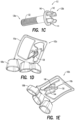
- the tensioning assembly 104 of the orthodontic expansion device 100 generally includes an adjustment rod 112, a piston 114, and a spring 116 in cooperative engagement with one another.
- the piston 114, spring 116, and a portion of the adjustment rod 112 are enclosed within a housing 118.
- the housing 118 has a first, closed end 120a ( FIG. 1A ) proximate the first lateral wing 102a and a second, open end 120b ( FIG. 1A ) opposite the first end.
- the adjustment rod 112, piston 114, and spring 116 each generally lie along a common central longitudinal axis Y within the housing 118, such that their individual longitudinal centerlines are coaxial and colinear with one another.
- the adjustment rod 112, piston 114, and the spring 116 engage one another to maintain the first lateral wing 102a and the second lateral wing 102b in an outwardly tensioned relationship away from each other.
- the outward tension places pressure on the molars and palate to cause the palate to expand.
- the tensioning assembly 104 can be adjusted to re-tension/ further expand the orthodontic expansion device 100.
- the spring 116 is seated within a cylinder 122 having a first, closed end (e.g., along the closed end 120a of the housing 118) proximate and attached to the first lateral wing 102a, and a second, open end opposite the closed end (e.g., along the open end 120b of the housing 118).
- the spring 116 includes a first end disposed along the first, closed end of the cylinder 122, and a second end opposite the first end of the spring 116.
- the piston 114 is also seated in the cylinder 122.
- the piston 114 is generally cylindrical in shape with a central / interior bore 124 extending along its length.
- the piston 114 includes a first shoulder 126a for engaging the second end of the spring 116, as will be described below.
- An interiorly threaded cylinder cap 128 engages threads along an exterior surface of the second, open end of the cylinder 122 to retain the spring 116 and a second shoulder 126b of the piston 114 within the cylinder 122.
- the cylinder 122 and cylinder cap 128 collectively form the housing 118.
- the closed end 120a of housing 118 (and more particularly cylinder 122), which at least partially forms and/or defines the first end 106a of the tensioning assembly 104, is pivotably joined to the first lateral wing 102a, as will be descibed in greater detail below.
- the adjustment rod 112 has a first end 130a and a second end 130b opposite one another.
- the first end 130a of the adjustment rod 112 includes threads 132 that engage corresponding threads 134 positioned along the central / interior bore 124 of the piston 114, such that the first end 130a of the adjustment rod 112 extends into the bore 124 of the piston 114, as shown in FIG. 1B .
- the portion of the adjustment rod 112 that extends into the bore 124 (e.g., the first end 130a of the adjustment rod 112a) lies within the tensioning assembly housing 118.
- the second end 130b of the adjustment rod which at least partially forms and/or defines the second end 106b of the tensioning assembly 104, is detachably connected to the second lateral wing 102b, as will be explained below.
- the piston 114 may move towards the closed end 120a of the housing 118. In doing so, the shoulder 126a of the piston 114 engages the spring 116 (e.g., the second end of the spring), compressing it towards the closed end 120a of the housing 118.
- the spring 116 e.g., the second end of the spring
- the at least partially compressed spring 116 exerts a pressure on the piston 114, which in turn exerts a pressure on the adjustment rod 112 threaded into the bore 124 of the piston 114, which in turn maintains the first and second lateral wings 102a, 102b of the orthodontic expansion device 100 in an opposed, outwardly urged tension away from one another. Described in another way, the wings 102a, 102b are pushed apart by a degree dictated by the tension of the spring 116 and the position of the rod 112 within the piston 114.
- a pressure is exerted outwardly and upwardly (or downwardly) on the respective molar bands 108a, 108b and frames 110a, 110b to expand the palate of the patient / wearer.
- the amount of pressure applied on the palate and teeth may vary depending on the selection of the spring 116 used in the tensioning assembly 104.
- the amount of pressure applied to the palate and teeth may be up to about 5000 grams (g).
- the pressure range may generally range from about 450 g to about 5000 g. This may be achieved using springs of different spring rates to cover smaller incremental ranges.
- the first end 106a of the tensioning assembly 104 is pivotably attached to the first lateral wing 102a and the second end 106b of the tensioning assembly 104 is removably attached to the second lateral wing 102b. This allows the tensioning assembly 104 to be partially detached and adjusted as needed to maintain the desired level of tension for palate expansion.
- the first end 106a of the tensioning assembly 104 (more particularly, housing 118, and even more particularly, cylinder 122) is pivotably connected by a hinge pin 136 to a hinge arm 138 extending from the frame 110a of the first lateral wing 102a.
- the hinge arm 138 seen for instance in FIG. 1D , may include an opening 139 to receive the hinge pin 136.
- the pivotable connection allows the tensioning assembly 104 to pivot or move away from the first lateral wing 102a to adjust the tension of the piston 114 against the spring 116.
- the second end 130b of the adjustment rod 112 includes a flattened area or flange 140 including a plurality of outwardly extending projections (e.g., teeth / clutch teeth) 142.
- the teeth 142 are configured for engaging a connector 144 that projects inwardly from the second lateral wing 102b towards the first lateral wing 102a.
- the connector 144 is configured with four bars 150 (having a cross-sectional cross-shaped configuration).
- the cross-shaped connector 144 is shaped and dimensioned to fit in the space(s) 146 between the teeth 142 along the second end 130b of the adjustment rod 112, with both the teeth 142 and connector 144 in any properly aligned rotational orientation (such that there are four possible proper rotational engagements at every 90 degree rotation).
- the teeth 142 of the adjustment rod 112 are shaped and dimensioned to fit in the spaces 148 around / adjacent to the bars 150 of the cross-shaped connector 144, with both the teeth 142 and connector 144 in any properly aligned rotational orientation (such that there are four possible proper rotational engagements at every 90 degree rotation).
- the adjustment rod 112 includes four teeth, each of which has a somewhat triangular shape when viewed as a projection. However, other possibilities are contemplated.
- the second end 106b ( FIG. 1A ) of the tensioning assembly 104 may be repeatedly detached and re-attached and the adjustment rod 112 may be repeatedly adjusted as needed to maintain the desired level of tension between the first and second lateral wings 102a, 102b.
- Adjustment of the orthodontic expansion device 100 may be illustrated generally in connection with FIGS. 2A-2F , which are only partially labeled.
- the adjustment rod 112 may be pressed towards the first lateral wing 102a to compress the spring within the tensioning assembly housing, as indicated by the arrow in FIG. 2A .
- flange 140 may be used as a solid surface to push against with an instrument such as a dental pick to compress the spring.
- the tensioning assembly 104 may then be rotated to a convenient position away from the first lateral wing 102a (e.g., towards the opening of the patient's mouth, or, for instance, towards the tongue when the orthodontic expansion device 100 is positioned in the maxilla of the patient), as shown in FIG. 2B .
- the tensioning assembly 104 is released, the spring will expand to its fully extended position (limited by the position of the threaded adjustment rod 112 and/or the piston and the cylinder cap), as shown in FIG. 2C .
- the tension of the device 100 may be adjusted by rotating the adjustment rod 112 the desired number of turns, for example, in one-quarter turn increments.
- rotating the adjustment rod 112 to the right (in a counter-clockwise direction) backs the adjustment rod 112 out of the piston, and increases the tension between the first and second lateral wings 102a, 102b when the tensioning assembly 104 is positioned between the first and second lateral wings 102a and 102b.
- rotating the adjustment rod to the left moves the adjustment rod away from the piston, and decreases the tension between the first and second lateral wings 102a, 102b.
- one complete turn may advance the adjustment rod a length of about 0.45 millimeters (mm). Every one-quarter turn may thus adjust the length by about 0.1125mm.
- the four locking teeth may each have a different color (not shown) to give a visual indication of the rotational advancement of the adjustment rod.
- the adjustment rod 112 can be reattached to the second lateral wing 102b by urging the tensioning assembly 104 back toward the first lateral wing 102a to compress the spring within the housing ( FIG. 2E ).
- the teeth 142 may then be aligned with the cross-shaped connector 144 in any one of the four connection positions (i.e., every 90° or 4 times per revolution), and releasing the tensioning assembly 104, as shown in FIG. 2F .
- FIG. 3A is schematic, perspective view of an alternate embodiment of an orthodontic expansion device 300.
- the orthodontic expansion device 300 includes several features similar to those of the orthodontic expansion device 100 illustrated in FIGS. 1A-1E and FIGS. 2A-2F , and described hereinabove, except as described below. For purposes of brevity, the description of similar features is not repeated here.
- the cylinder cap 128 of the device 100 of FIG. 1A is omitted, and instead, the orthodontic expansion device 300 is provided with a retention crimp 350 positioned along a periphery of the open end of the cylinder 322.
- a plurality of retention crimps 350 may be provided.
- FIG. 3B which shows the cylinder 322 and piston 314 in isolation
- the retention crimps 350 are bent inwardly towards the interior of the cylinder 322 to maintain the piston 314 and spring (not shown in FIG. 3B ) within the cylinder 322.
- there are three retention crimps 350 In the illustrated orthodontic expansion device 300, there are three retention crimps 350.
- elimination of the cylinder cap 128 FIG. 1A
- the housing 318' now including only cylinder 322 and crimps 350
- the housing 318' now including only cylinder 322 and crimps 350
- the second end 330b of the adjustment rod 312 engages the second lateral wing 310b differently than the orthodontic expansion device 100 of FIG. 1A .
- the flattened area or flange 340 of the adjustment rod 312 of the orthodontic expansion device 300 of FIG. 3A includes a recess 352 configured (e.g., shaped) to receive a corresponding shaped connector / projection 354 that extends inwardly from the second lateral wing 302b towards the first lateral wing 302a.
- both the recess 352 and projection / connector 354 have a generally hexagonal shape (e.g., with six sides / flattened surfaces), such that the adjustment rod 312 can be turned six times and fit in six different rotational positions (one for each side of the hexagon).
- a generally hexagonal shape e.g., with six sides / flattened surfaces
- the adjustment rod 312 can be turned six times and fit in six different rotational positions (one for each side of the hexagon).
- other shapes may be used for the recess 352 and projection 354 that may provide other numbers of rotational fit possibilities.
- each side of the hexagonal recess 352 and/or projection 354 may be provided with markings or other indicia (not shown) to assist with indicating the degree of rotation.
- the fundamental concepts presented herein can readily be adapted to similar or related concepts.
- the present design can be readily adapted to devices used in conjunction with orthopedic surgery for bone expansion of either long bones of the limbs or the jaw bone during distraction osteogenesis, or the like. Accordingly, the present disclosure should not be interpreted as being limited solely to palate expansion devices, despite the emphasis thereon for exemplary purposes.
- This disclosure in various embodiments, configurations and aspects, includes components, methods, processes, systems, and/or apparatuses as depicted and described herein, including various embodiments, sub-combinations, and subsets thereof.
- This disclosure contemplates, in various embodiments, configurations and aspects, the actual or optional use or inclusion of, e.g., components or processes as may be well-known or understood in the art and consistent with this disclosure though not depicted and/or described herein.
- each of the expressions “at least one of A, B and C”, “at least one of A, B, or C”, “one or more of A, B, and C", “one or more of A, B, or C" and "A, B, and/or C” means A alone, B alone, C alone, A and B together, A and C together, B and C together, or A, B and C together.
- a value modified by a term such as “about” is not to be limited to the precise value specified. In some instances, the approximating language may correspond to the precision of an instrument for measuring the value. Terms such as “first,” “second,” “upper,” “lower” etc. are used to identify one element from another, and unless otherwise specified are not meant to refer to a particular order or number of elements.
- the terms “may” and “may be” indicate a possibility of an occurrence within a set of circumstances; a possession of a specified property, characteristic or function; and/or qualify another verb by expressing one or more of an ability, capability, or possibility associated with the qualified verb. Accordingly, usage of “may” and “may be” indicates that a modified term is apparently appropriate, capable, or suitable for an indicated capacity, function, or usage, while taking into account that in some circumstances the modified term may sometimes not be appropriate, capable, or suitable. For example, in some circumstances an event or capacity can be expected, while in other circumstances the event or capacity cannot occur - this distinction is captured by the terms “may” and “may be.”
Landscapes
- Health & Medical Sciences (AREA)
- Oral & Maxillofacial Surgery (AREA)
- Dentistry (AREA)
- Epidemiology (AREA)
- Life Sciences & Earth Sciences (AREA)
- Animal Behavior & Ethology (AREA)
- General Health & Medical Sciences (AREA)
- Public Health (AREA)
- Veterinary Medicine (AREA)
- Dental Tools And Instruments Or Auxiliary Dental Instruments (AREA)
Claims (15)
- Kieferorthopädische Erweiterungsvorrichtung (100, 300), umfassend:einen ersten seitlichen Flügel (102a, 302a) und einen zweiten seitlichen Flügel (102b, 302b), die einander gegenüberliegen, wobei der erste seitliche Flügel und der zweite seitliche Flügel jeweils Folgendes umfassen:ein Molarenband (108a, 108b), das so geformt ist, dass es einen Molaren eines Patienten aufnehmen kann, undeinen Gaumenrahmen (110a, 110b), der sich schräg vom Molarenband erstreckt, wobei der Gaumenrahmen so geformt ist, dass er gegen den Gaumen des Patienten anliegt; undeinen Scharnierarm (138), der sich vom Gaumenrahmen (110a) des ersten seitlichen Flügels erstreckt;eine Spannvorrichtung (104), die zwischen dem ersten und zweiten seitlichen Flügel angeordnet ist, wobei die Spannvorrichtung Folgendes umfasst:ein erstes Ende (106a), das schwenkbar am Scharnierarm des ersten seitlichen Flügels befestigt ist; undein zweites Ende (106b), das lösbar am zweiten seitlichen Flügel befestigt ist;einen Kolben (114, 314), der zwischen dem ersten Ende und dem zweiten Ende angeordnet ist;eine Einstellstange (112, 312), die ein erstes Stangenende umfasst, das ein Gewinde einschließt, das ein entsprechendes Gewinde in Eingriff nimmt, das sich entlang einer Innenbohrung des Kolbens erstreckt, sodass die Einstellstange mindestens teilweise in die Innenbohrung des Kolbens geschraubt ist; undeine Feder (116),wobei die Einstellstange den Kolben gegen die Feder zurückhält, um den ersten seitlichen Flügel und den zweiten seitlichen Flügel in einer nach außen gespannten Beziehung voneinander weg zu halten.
- Kieferorthopädische Erweiterungsvorrichtung (100, 300) nach Anspruch 1, wobei die Spannvorrichtung (104) am zweiten seitlichen Flügel (102b, 302b) lösbar befestigt ist, sodass die Spannung der kieferorthopädischen Erweiterungsvorrichtung einstellbar ist.
- Kieferorthopädische Erweiterungsvorrichtung (100, 300) nach Anspruch 1, wobei die Einstellstange (112, 312) in Richtung des Kolbens beweglich ist, um die Feder zu komprimieren und die Spannung zwischen dem ersten seitlichen Flügel und dem zweiten seitlichen Flügel zu erhöhen.
- Kieferorthopädische Erweiterungsvorrichtung (100, 300) nach Anspruch 1, wobei der Kolben (114, 314) eine Schulter umfasst, die für den Eingriff mit der Feder konfiguriert ist.
- Kieferorthopädische Erweiterungsvorrichtung (100, 300) nach Anspruch 1, wobei die Einstellstange (112, 312) ferner Folgendes umfasst:
ein zweites Stangenende, das einen Zahn (142) umfasst, der mit einem kreuzförmigen Verbinder (144) in Eingriff steht, der vom zweiten seitlichen Flügel nach innen vorsteht. - Kieferorthopädische Erweiterungsvorrichtung (100, 300) nach Anspruch 5, die ferner vier voneinander beabstandete Zähne (142) zum Aufnehmen des kreuzförmigen Verbinders (144) dazwischen umfasst.
- Kieferorthopädische Erweiterungsvorrichtung (100, 300) nach Anspruch 5, wobei der Zahn eine Mehrzahl von Zähnen (142) ist und die Spannvorrichtung dazu konfiguriert ist, durch Außereingriffbringen der Mehrzahl von Zähnen aus dem kreuzförmigen Verbinder am zweiten seitlichen Flügel lösbar befestigt zu werden.
- Kieferorthopädische Erweiterungsvorrichtung (100, 300) nach Anspruch 7, wobei die Einstellstange in Richtung des ersten seitlichen Flügels beweglich ist, um die Feder (116) zu komprimieren, sodass der Zahn aus dem kreuzförmigen Verbinder außer Eingriff gebracht werden kann.
- Kieferorthopädische Erweiterungsvorrichtung (100, 300) nach Anspruch 1, wobei der Kolben, die Feder und ein Teil der Einstellstange in einem Gehäuse eingeschlossen sind, und die Einstellstange, der Kolben und die Feder koaxial zueinander ausgerichtet sind.
- Kieferorthopädische Erweiterungsvorrichtung (100, 300) nach Anspruch 9, wobei das Gehäuse mit dem ersten seitlichen Flügel schwenkbar verbunden ist.
- Kieferorthopädische Erweiterungsvorrichtung (100, 300) nach Anspruch 1,wobei das erste Ende (106a), das am ersten seitlichen Flügel (102a, 302a) schwenkbar befestigt ist, ein erstes, geschlossenes Ende eines Zylinders umfasst und das zweite Ende (106b), das am zweiten seitlichen Flügel (102b, 302b) lösbar befestigt ist, ein zweites, offenes Ende gegenüber dem geschlossenen Ende umfasst,die Feder innerhalb des Zylinders positioniert ist, undsich der Kolben benachbart zur Feder befindet.
- Kieferorthopädische Erweiterungsvorrichtung (100, 300) nach Anspruch 11, wobei die Feder Folgendes einschließt:ein erstes Ende, das entlang des ersten, geschlossenen Endes des Zylinders angeordnet ist, undein zweites Ende gegenüber dem ersten Ende der Feder.
- Kieferorthopädische Erweiterungsvorrichtung (100, 300) nach Anspruch 11, wobei der Kolben Folgendes umfasst:eine erste Schulter zum Ineingriffnehmen des zweiten Endes der Feder; undeine zweite Schulter, die innerhalb des Zylinders positioniert ist.
- Kieferorthopädische Erweiterungsvorrichtung (100) nach Anspruch 13, ferner umfassend:eine Zylinderkappe mit Innengewinde, die eine Mehrzahl von Innengewinden aufweist,wobei das Innengewinde Außengewinde in Eingriff nimmt, die sich entlang einer Außenfläche des zweiten, offenen Endes des Zylinders erstrecken, um die Feder und die zweite Schulter des Kolbens innerhalb des Zylinders zu halten.
- Kieferorthopädische Erweiterungsvorrichtung (300) nach Anspruch 11, wobei der Zylinder ferner Folgendes umfasst:eine Mehrzahl von Rückhalte-Crimps entlang eines Umfangs des zweiten, offenen Endes des Zylinders,wobei die Mehrzahl von Rückhalte-Crimps nach innen in Richtung eines Inneren des Zylinders gebogen sind, um den Kolben und die Feder innerhalb des Zylinders zu halten.
Applications Claiming Priority (2)
| Application Number | Priority Date | Filing Date | Title |
|---|---|---|---|
| US201962857294P | 2019-06-05 | 2019-06-05 | |
| PCT/US2020/036033 WO2020247570A1 (en) | 2019-06-05 | 2020-06-04 | Orthodontic expansion device |
Publications (4)
| Publication Number | Publication Date |
|---|---|
| EP3979935A1 EP3979935A1 (de) | 2022-04-13 |
| EP3979935A4 EP3979935A4 (de) | 2023-09-13 |
| EP3979935B1 true EP3979935B1 (de) | 2025-05-21 |
| EP3979935C0 EP3979935C0 (de) | 2025-05-21 |
Family
ID=73652041
Family Applications (1)
| Application Number | Title | Priority Date | Filing Date |
|---|---|---|---|
| EP20818545.4A Active EP3979935B1 (de) | 2019-06-05 | 2020-06-04 | Kieferorthopädische expansionsvorrichtung |
Country Status (4)
| Country | Link |
|---|---|
| US (1) | US20220257348A1 (de) |
| EP (1) | EP3979935B1 (de) |
| CA (1) | CA3140304A1 (de) |
| WO (1) | WO2020247570A1 (de) |
Family Cites Families (20)
| Publication number | Priority date | Publication date | Assignee | Title |
|---|---|---|---|---|
| US597582A (en) * | 1898-01-18 | Teeth-regulator | ||
| DE211137C (de) | 1908-07-05 | 1909-06-21 | Landsberger Richard | Vorrichtung zur dehnung des klefers mittels federnder schraube |
| FR998076A (fr) * | 1949-09-29 | 1952-01-14 | écarteur de bouche | |
| US3832778A (en) * | 1972-11-29 | 1974-09-03 | M Wallshein | Orthodontic biassing device |
| US4200979A (en) * | 1977-04-07 | 1980-05-06 | Melvin Wallshein | Orthodontic biassing device with screw disengagement preventing means |
| US4571178A (en) * | 1984-12-07 | 1986-02-18 | Rosenberg Farel A | Forward-backward molar controlling and positioning dental appliance |
| US5829975A (en) * | 1997-10-01 | 1998-11-03 | Gold; Stephen | Orthodontic appliance |
| US7094051B2 (en) * | 1998-04-23 | 2006-08-22 | Williams Michael O | Orthodontic appliance |
| US6402510B1 (en) * | 1998-04-23 | 2002-06-11 | Michael O. Williams | Buccal tipping-resistant mandibular and maxillary arch expander |
| US6358255B1 (en) * | 2000-03-06 | 2002-03-19 | Micerium S.R.L. | Distraction osteogenesis device and method |
| US6908306B2 (en) * | 2001-11-15 | 2005-06-21 | American Orthodontics Corp. | Orthodontic distalizing apparatus |
| US20080072915A1 (en) * | 2003-08-08 | 2008-03-27 | Nelissen Jozef F | Device for treating nighttime breathing problems |
| US7074036B1 (en) * | 2005-05-16 | 2006-07-11 | Ahmet Ozlem Keles | Palatal expansion device and methods |
| US7500851B2 (en) * | 2006-07-01 | 2009-03-10 | Williams Michael O | Maxillary arch expander unbanded to teeth |
| DE112009000857T5 (de) * | 2008-04-09 | 2011-05-05 | 3M Innovative Properties Co., Saint Paul | Linguale orthodontische Vorrichtung mit entfernbarem Teilstück |
| US20130252195A1 (en) * | 2012-03-26 | 2013-09-26 | President And Fellows Of Harvard College | Orthodontic expander system and method |
| ITFI20130028A1 (it) * | 2013-02-09 | 2014-08-10 | Leone Spa | Espansore ortodontico. |
| FR3049849B1 (fr) * | 2016-04-08 | 2021-02-19 | David Atlan | Dispositif d'expansion palatine (disjoncteur maxillaire) |
| EP3448298B1 (de) * | 2016-04-26 | 2020-03-11 | Keles, Ahmet Ozlem | Orthodontische gaumen- und kieferexpansionsvorrichtung mit einfacher befestigung im/lösung vom inneren des mundes |
| US10258379B2 (en) * | 2016-12-09 | 2019-04-16 | Metal Industries Research & Development Centre | Mandibular fixation device |
-
2020
- 2020-06-04 CA CA3140304A patent/CA3140304A1/en active Pending
- 2020-06-04 WO PCT/US2020/036033 patent/WO2020247570A1/en not_active Ceased
- 2020-06-04 US US17/613,526 patent/US20220257348A1/en active Pending
- 2020-06-04 EP EP20818545.4A patent/EP3979935B1/de active Active
Also Published As
| Publication number | Publication date |
|---|---|
| US20220257348A1 (en) | 2022-08-18 |
| WO2020247570A1 (en) | 2020-12-10 |
| EP3979935C0 (de) | 2025-05-21 |
| CA3140304A1 (en) | 2020-12-10 |
| EP3979935A4 (de) | 2023-09-13 |
| EP3979935A1 (de) | 2022-04-13 |
| WO2020247570A9 (en) | 2021-11-11 |
Similar Documents
| Publication | Publication Date | Title |
|---|---|---|
| EP1956987B1 (de) | Sternum-nahtklammer und gerät zum positionieren und anziehen der klammer | |
| US11628045B2 (en) | Torque wrench for implant procedure | |
| JP7356086B2 (ja) | 改良された上顎の拡大装置および前方牽引装置 | |
| JP2007536001A (ja) | 顔面中央伸延装置 | |
| US20170290643A1 (en) | Intraoral expander device | |
| EP3713509B1 (de) | Oberkieferexpander, der eine dentale ausrichtvorrichtung und orthodontische schrauben umfasst | |
| US7074036B1 (en) | Palatal expansion device and methods | |
| KR20180132320A (ko) | 상악골과 안면골 확장장치 | |
| KR20250151290A (ko) | 임플란트 시술용 토크렌치 | |
| EP4188273B1 (de) | Vorrichtung zur oberkieferexpansion | |
| US20220257348A1 (en) | Orthodontic expansion device | |
| US9622801B1 (en) | Mandibular distractor device | |
| KR101405828B1 (ko) | 치과용 토크 렌치 | |
| US20200337804A1 (en) | Retainerless dental matrix band system | |
| US1597529A (en) | Dental appliance | |
| KR20220050856A (ko) | 임플란트 시술용 토크렌치 | |
| KR20100090399A (ko) | 임플란트 시술용 토오크 렌치 | |
| KR20090000137U (ko) | 치과용 교합지 홀더 | |
| EP2331006A2 (de) | Kieferorthopädisches bracket und zahnspange mit solchen brackets |
Legal Events
| Date | Code | Title | Description |
|---|---|---|---|
| STAA | Information on the status of an ep patent application or granted ep patent |
Free format text: STATUS: THE INTERNATIONAL PUBLICATION HAS BEEN MADE |
|
| PUAI | Public reference made under article 153(3) epc to a published international application that has entered the european phase |
Free format text: ORIGINAL CODE: 0009012 |
|
| STAA | Information on the status of an ep patent application or granted ep patent |
Free format text: STATUS: REQUEST FOR EXAMINATION WAS MADE |
|
| 17P | Request for examination filed |
Effective date: 20220105 |
|
| AK | Designated contracting states |
Kind code of ref document: A1 Designated state(s): AL AT BE BG CH CY CZ DE DK EE ES FI FR GB GR HR HU IE IS IT LI LT LU LV MC MK MT NL NO PL PT RO RS SE SI SK SM TR |
|
| DAV | Request for validation of the european patent (deleted) | ||
| DAX | Request for extension of the european patent (deleted) | ||
| RAP3 | Party data changed (applicant data changed or rights of an application transferred) |
Owner name: ACHAEMENID, LLC |
|
| A4 | Supplementary search report drawn up and despatched |
Effective date: 20230810 |
|
| RIC1 | Information provided on ipc code assigned before grant |
Ipc: A61C 8/00 20060101ALI20230804BHEP Ipc: A61C 7/18 20060101ALI20230804BHEP Ipc: A61C 7/10 20060101ALI20230804BHEP Ipc: A61C 3/00 20060101ALI20230804BHEP Ipc: A61B 17/88 20060101ALI20230804BHEP Ipc: A61B 17/80 20060101AFI20230804BHEP |
|
| GRAP | Despatch of communication of intention to grant a patent |
Free format text: ORIGINAL CODE: EPIDOSNIGR1 |
|
| STAA | Information on the status of an ep patent application or granted ep patent |
Free format text: STATUS: GRANT OF PATENT IS INTENDED |
|
| INTG | Intention to grant announced |
Effective date: 20241218 |
|
| GRAS | Grant fee paid |
Free format text: ORIGINAL CODE: EPIDOSNIGR3 |
|
| GRAA | (expected) grant |
Free format text: ORIGINAL CODE: 0009210 |
|
| STAA | Information on the status of an ep patent application or granted ep patent |
Free format text: STATUS: THE PATENT HAS BEEN GRANTED |
|
| AK | Designated contracting states |
Kind code of ref document: B1 Designated state(s): AL AT BE BG CH CY CZ DE DK EE ES FI FR GB GR HR HU IE IS IT LI LT LU LV MC MK MT NL NO PL PT RO RS SE SI SK SM TR |
|
| REG | Reference to a national code |
Ref country code: GB Ref legal event code: FG4D |
|
| REG | Reference to a national code |
Ref country code: CH Ref legal event code: EP |
|
| REG | Reference to a national code |
Ref country code: DE Ref legal event code: R096 Ref document number: 602020051731 Country of ref document: DE |
|
| REG | Reference to a national code |
Ref country code: IE Ref legal event code: FG4D |
|
| U01 | Request for unitary effect filed |
Effective date: 20250611 |
|
| U07 | Unitary effect registered |
Designated state(s): AT BE BG DE DK EE FI FR IT LT LU LV MT NL PT RO SE SI Effective date: 20250623 |
|
| U20 | Renewal fee for the european patent with unitary effect paid |
Year of fee payment: 6 Effective date: 20250624 |
|
| PG25 | Lapsed in a contracting state [announced via postgrant information from national office to epo] |
Ref country code: ES Free format text: LAPSE BECAUSE OF FAILURE TO SUBMIT A TRANSLATION OF THE DESCRIPTION OR TO PAY THE FEE WITHIN THE PRESCRIBED TIME-LIMIT Effective date: 20250521 |
|
| PG25 | Lapsed in a contracting state [announced via postgrant information from national office to epo] |
Ref country code: GR Free format text: LAPSE BECAUSE OF FAILURE TO SUBMIT A TRANSLATION OF THE DESCRIPTION OR TO PAY THE FEE WITHIN THE PRESCRIBED TIME-LIMIT Effective date: 20250822 Ref country code: NO Free format text: LAPSE BECAUSE OF FAILURE TO SUBMIT A TRANSLATION OF THE DESCRIPTION OR TO PAY THE FEE WITHIN THE PRESCRIBED TIME-LIMIT Effective date: 20250821 |
|
| PG25 | Lapsed in a contracting state [announced via postgrant information from national office to epo] |
Ref country code: PL Free format text: LAPSE BECAUSE OF FAILURE TO SUBMIT A TRANSLATION OF THE DESCRIPTION OR TO PAY THE FEE WITHIN THE PRESCRIBED TIME-LIMIT Effective date: 20250521 |
|
| PG25 | Lapsed in a contracting state [announced via postgrant information from national office to epo] |
Ref country code: HR Free format text: LAPSE BECAUSE OF FAILURE TO SUBMIT A TRANSLATION OF THE DESCRIPTION OR TO PAY THE FEE WITHIN THE PRESCRIBED TIME-LIMIT Effective date: 20250521 |
|
| PG25 | Lapsed in a contracting state [announced via postgrant information from national office to epo] |
Ref country code: RS Free format text: LAPSE BECAUSE OF FAILURE TO SUBMIT A TRANSLATION OF THE DESCRIPTION OR TO PAY THE FEE WITHIN THE PRESCRIBED TIME-LIMIT Effective date: 20250821 |
|
| PG25 | Lapsed in a contracting state [announced via postgrant information from national office to epo] |
Ref country code: IS Free format text: LAPSE BECAUSE OF FAILURE TO SUBMIT A TRANSLATION OF THE DESCRIPTION OR TO PAY THE FEE WITHIN THE PRESCRIBED TIME-LIMIT Effective date: 20250921 |
|
| PG25 | Lapsed in a contracting state [announced via postgrant information from national office to epo] |
Ref country code: SM Free format text: LAPSE BECAUSE OF FAILURE TO SUBMIT A TRANSLATION OF THE DESCRIPTION OR TO PAY THE FEE WITHIN THE PRESCRIBED TIME-LIMIT Effective date: 20250521 |
|
| PG25 | Lapsed in a contracting state [announced via postgrant information from national office to epo] |
Ref country code: CZ Free format text: LAPSE BECAUSE OF FAILURE TO SUBMIT A TRANSLATION OF THE DESCRIPTION OR TO PAY THE FEE WITHIN THE PRESCRIBED TIME-LIMIT Effective date: 20250521 |
|
| PG25 | Lapsed in a contracting state [announced via postgrant information from national office to epo] |
Ref country code: SK Free format text: LAPSE BECAUSE OF FAILURE TO SUBMIT A TRANSLATION OF THE DESCRIPTION OR TO PAY THE FEE WITHIN THE PRESCRIBED TIME-LIMIT Effective date: 20250521 |
|
| REG | Reference to a national code |
Ref country code: CH Ref legal event code: H13 Free format text: ST27 STATUS EVENT CODE: U-0-0-H10-H13 (AS PROVIDED BY THE NATIONAL OFFICE) Effective date: 20260127 |
|
| PG25 | Lapsed in a contracting state [announced via postgrant information from national office to epo] |
Ref country code: MC Free format text: LAPSE BECAUSE OF FAILURE TO SUBMIT A TRANSLATION OF THE DESCRIPTION OR TO PAY THE FEE WITHIN THE PRESCRIBED TIME-LIMIT Effective date: 20250521 |
|
| PLBE | No opposition filed within time limit |
Free format text: ORIGINAL CODE: 0009261 |
|
| STAA | Information on the status of an ep patent application or granted ep patent |
Free format text: STATUS: NO OPPOSITION FILED WITHIN TIME LIMIT |
|
| REG | Reference to a national code |
Ref country code: CH Ref legal event code: L10 Free format text: ST27 STATUS EVENT CODE: U-0-0-L10-L00 (AS PROVIDED BY THE NATIONAL OFFICE) Effective date: 20260402 |
|
| PG25 | Lapsed in a contracting state [announced via postgrant information from national office to epo] |
Ref country code: IE Free format text: LAPSE BECAUSE OF NON-PAYMENT OF DUE FEES Effective date: 20250604 |
|
| PG25 | Lapsed in a contracting state [announced via postgrant information from national office to epo] |
Ref country code: CH Free format text: LAPSE BECAUSE OF NON-PAYMENT OF DUE FEES Effective date: 20250630 |
|
| 26N | No opposition filed |
Effective date: 20260224 |
|
| GBPC | Gb: european patent ceased through non-payment of renewal fee |
Effective date: 20250821 |