EP3979769A1 - Baugruppe für ein induktionskochfeld und induktionskochfeld - Google Patents
Baugruppe für ein induktionskochfeld und induktionskochfeld Download PDFInfo
- Publication number
- EP3979769A1 EP3979769A1 EP21197616.2A EP21197616A EP3979769A1 EP 3979769 A1 EP3979769 A1 EP 3979769A1 EP 21197616 A EP21197616 A EP 21197616A EP 3979769 A1 EP3979769 A1 EP 3979769A1
- Authority
- EP
- European Patent Office
- Prior art keywords
- coil
- induction coil
- carrier
- designed
- assembly
- Prior art date
- Legal status (The legal status is an assumption and is not a legal conclusion. Google has not performed a legal analysis and makes no representation as to the accuracy of the status listed.)
- Granted
Links
Images


Classifications
-
- H—ELECTRICITY
- H05—ELECTRIC TECHNIQUES NOT OTHERWISE PROVIDED FOR
- H05B—ELECTRIC HEATING; ELECTRIC LIGHT SOURCES NOT OTHERWISE PROVIDED FOR; CIRCUIT ARRANGEMENTS FOR ELECTRIC LIGHT SOURCES, IN GENERAL
- H05B6/00—Heating by electric, magnetic or electromagnetic fields
- H05B6/02—Induction heating
- H05B6/10—Induction heating apparatus, other than furnaces, for specific applications
- H05B6/12—Cooking devices
- H05B6/1209—Cooking devices induction cooking plates or the like and devices to be used in combination with them
-
- H—ELECTRICITY
- H05—ELECTRIC TECHNIQUES NOT OTHERWISE PROVIDED FOR
- H05B—ELECTRIC HEATING; ELECTRIC LIGHT SOURCES NOT OTHERWISE PROVIDED FOR; CIRCUIT ARRANGEMENTS FOR ELECTRIC LIGHT SOURCES, IN GENERAL
- H05B2206/00—Aspects relating to heating by electric, magnetic, or electromagnetic fields covered by group H05B6/00
- H05B2206/02—Induction heating
- H05B2206/022—Special supports for the induction coils
Definitions
- the invention relates to an assembly for an induction hob of the type specified in the preamble of patent claim 1 and an induction hob of the type specified in the preamble of patent claim 10.
- the known assemblies for induction hobs include at least one induction coil for inductively heating a hotplate arranged on a cover plate of the induction hob, the induction coil being positioned and fixed on a carrier plate of the assembly when the assembly is assembled.
- the invention therefore addresses the problem of improving an assembly for an induction hob and an induction hob.
- this problem is solved by an assembly for an induction hob with the features of patent claim 1 . Furthermore, this problem is solved by an induction hob with the features of claim 10.
- the induction hobs according to the invention can be built-in hobs, for example. Furthermore, the induction hobs according to the invention can be designed as household appliances or as commercial appliances, ie hobs for the professional sector. Advantageous configurations and developments of the invention result from the following dependent claims.
- the advantage that can be achieved with the invention is, in particular, that an assembly for an induction hob and an induction hob is improved. Due to the design of the assembly for an induction hob and the induction hob according to the invention, the assembly of an assembly for an induction hob and thus the production of an induction hob equipped with it is significantly easier. Additional fastening means are not required in order to position and fix the at least one induction coil relative to the carrier plate during the production of the induction hob according to the invention, in order to then mount the cover plate of the induction hob. Furthermore, this enables savings in components and production steps. The overall height of the coil element can also be reduced compared to the prior art. This and moreover simplifies the logistics and warehousing accordingly.
- the assembly according to the invention for an induction hob can be freely selected within wide, suitable limits in terms of type, function, material, dimensioning and arrangement. See also the above statements on the design of the induction hob according to the invention.
- At least one of the support form-fitting means is designed as a depression or as a latching projection and the corresponding coil form-fitting means is designed as a latching projection, preferably that the depression is designed as an opening and/or the latching projection as a Embossing are formed / is.
- this carrier form-fitting means and this coil form-fitting means corresponding thereto are designed in a structurally particularly simple and robust manner.
- a force fit, ie a friction fit for the force-transmitting connection between the induction coil on the one hand and the carrier plate on the other side can be easily implemented with such form-fit means without additional components. Accordingly, even larger forces can be transmitted between the induction coil and the carrier plate with the above-mentioned form-fitting means.
- the coil form-fitting means are designed as latching projections that engage in or on the carrier form-fitting means.
- the latching projections extend in the radial direction beyond the peripheral edge of the induction coil.
- the latching projections are designed as hollow bodies, in particular as half hollow cylinders.
- the latching projections can also be extended beyond the underside of the induction coil, the underside of the induction coil being the side which faces the carrier plate in the mounted state of the induction coil. In the mounted state, such a latching projection would then engage in an opening in the carrier plate, which is formed in the area of a carrier form-fitting means.
- the latching projections are designed in particular as hollow bodies, for example as half hollow cylinders.
- a further advantageous development of the assembly according to the invention for an induction cooktop provides that at least one of the carrier form-fitting means is designed as a carrier plate hook, with the carrier plate hook encompassing the coil form-fitting means designed as an edge of the corresponding induction coil when the assembly is assembled, preferably that at least one of the at least one carrier form-fitting means designed as a carrier plate hook is arranged in such a way that a connection cable of the aforementioned induction coil acts on this induction coil and prestresses the induction coil perpendicularly to the carrier plate Lifting force can be accommodated by means of this carrier plate hook.
- the coil form-locking means corresponding thereto is realized in a structurally particularly simple manner, with no modification of the induction coil being necessary to form this coil form-locking means.
- the preferred embodiment of this further development is particularly advantageous since undesired forces are introduced into the assembly, in particular through the connection cable of the induction coil, which lead to a prestressing of the induction coil perpendicular to the carrier plate.
- a particularly advantageous development of the assembly according to the invention for an induction hob provides that the coil form-locking means and the carrier form-locking means corresponding to these coil form-locking means are at least partially arranged on opposite sides of the induction coil. In this way, the induction coil can be positioned and fixed relative to the carrier plate over the entire extent of the induction coil in a manner that is particularly simple in terms of design and production technology.
- Support plate interlocking means and the induction coil with the coil interlocking means are designed and arranged in such a way that they are coordinated with one another so that the induction coil can be positioned and fixed relative to the carrier plate by rotating it about an axis of rotation for the purpose of transferring the assembly into its assembled state, preferably that the induction coil by means of a single rotation this axis of rotation can be positioned and fixed relative to the support plate. This greatly simplifies the transfer of the assembly according to the invention for an induction hob into its assembled state in terms of handling.
- the axis of rotation it is possible for the axis of rotation to run parallel to the carrier plate, with the at least one carrier positive-locking means arranged on the rotational axis side being designed as a carrier plate hook and the corresponding coil positive-locking means being designed as an edge of the induction coil facing the axis of rotation, and with the at least one carrier positive-locking means arranged remote from the axis of rotation being a perpendicular to the carrier plate extending carrier plate projection and the coil form-fitting means corresponding thereto are formed as an edge of the induction coil facing away from the axis of rotation.
- the handling when transferring the assembly according to the invention into its assembled state is very simple, so that the ergonomics in the production of the induction hob are additionally improved.
- the axis of rotation may run perpendicularly to the carrier plate, with the at least two carrier positive-locking means arranged on opposite sides of the induction coil being designed as carrier plate hooks and the corresponding coil positive-locking means being designed as an edge of the induction coil.
- This provides an ergonomically equivalent alternative to the aforementioned embodiment for transferring the assembly according to the invention to its assembled state.
- this development has the further advantage that the carrier plate encompasses the induction coil on both sides, that is to say on both opposite sides of the induction coil, when the assembly is in the assembled state.
- a further particularly advantageous development of the assembly according to the invention for an induction hob provides that the carrier plate and the induction coil are designed for a multiple form-fitting of mutually corresponding carrier form-fitting means and coil form-fitting means.
- the form-fitting connection between the induction coil on the one hand and the carrier plate on the other hand is further improved in the assembled state of the assembly. Accordingly, for example, positioning and fixing of the induction coil relative to the carrier plate in a number of spatial directions is made possible in a manner that is simple in terms of design and production technology.
- the individual carrier positive-locking means and coil positive-locking means in connection with the carrier plate and the induction coil can be designed to be coordinated with one another in such a way that the respective pairings of mutually corresponding carrier positive-locking means and coil positive-locking means interact when the assembly according to the invention is transferred to its assembled state and/or in its assembled state supplement, so that when the assembly according to the invention is transferred into its assembled state and/or in its assembled state, there is a combined effect of at least some of the aforementioned pairings of positive-locking means.
- the carrier form-fitting means and coil form-fitting means that correspond to one another are at least partially designed to be coordinated with one another in such a way that the induction coil when the assembly is assembled is additionally held by a force fit, i.e. by frictional engagement, between at least one carrier form-fitting means and the is positioned and fixed to corresponding coil form-fitting means.
- a force fit i.e. by frictional engagement
- the assembly 2 for an induction hob comprises at least one induction coil 4 for inductive heating of a hotplate, also not shown, arranged on a cover plate of the induction hob, not shown, with the induction coil 4 in a 1 shown assembly state of the assembly 2 is positioned and fixed on a support plate 6 of the assembly 2.
- the induction coil 4 has coil form-locking means 8, 10 and the carrier plate 6 has carrier form-locking means 12, 14 designed to correspond to the coil form-locking means 8, 10, the induction coil 4 being positively locked by means of the coil form-locking means 8, 10 and the carrier form-locking means 12, 14 when the assembly 2 is in the assembled state is positioned and fixed on the support plate 6.
- the coil form-fitting means 8, 10 of the induction coil 4 are each formed as an edge of the induction coil 4 in the present exemplary embodiment.
- the induction coil 4 is therefore not specially designed to form the coil form-locking means 8, 10.
- the carrier form-locking means 12, 14 corresponding to the coil form-locking means 8, 10 are embodied on the one hand as two carrier plate hooks arranged parallel to one another and, on the other hand, as two carrier form-locking means 14 embodied perpendicularly to the carrier plate 6 and parallel to one another. See also also the Figures 2a and 2b .
- the carrier form-fitting means 12 designed as a carrier plate hook encompasses the coil form-fitting means 8 designed as the edge of the induction coil 4, with the carrier form-fitting means 12 designed as a carrier plate hook being arranged in such a way that a connecting cable 15 of the aforementioned induction coil 4 acts on this induction coil 4, the induction coil 4 perpendicular to the carrier plate 6, the lifting force can be absorbed by means of this carrier form-fitting means 12.
- the induction coil 4 and the carrier plate 6 have, in addition to the above-mentioned form-fitting means 8, 10, 12, 14, other form-fitting means which correspond to one another.
- the induction coil 4 has two coil form-fitting means 16, 18 designed as so-called slugs Figures 1 to 2b shown assembly state of the assembly 2 with corresponding and designed as openings in the support plate 6 carrier form-fitting means 20, 22 latchingly engaged.
- the coil form-locking means 16, 18 are either latching projections that snap into or onto the carrier form-locking means 20, 22.
- the latching projections extend in the radial direction beyond the peripheral edge of the induction coil 4 .
- the latching projections are designed as hollow bodies, in particular as half hollow cylinders.
- coil form-locking means 16, 18 and the corresponding carrier form-locking means 20, 22 are designed to be coordinated with one another in such a way that these form-locking means 16, 18, 20, 22 in the assembled state of the assembly 2 also form a force-fit connection, i.e. a friction-locking connection, in addition to a form-fit connection .
- the coil form-locking means 8, 10 and 16, 18 and the carrier form-locking means 12, 14 and 20, 22 corresponding to these coil form-locking means 8, 10, 16, 18 are each arranged on opposite sides of the induction coil 4.
- the carrier plate 6 with the carrier plate positive-locking means 12, 14 and 20, 22 and the induction coil 4 with the coil positive-locking means 8, 10 and 16, 18 are designed and arranged in such a way that the induction coil 4 is adapted for the purpose of transferring the assembly 2 in the assembled state can be positioned and fixed relative to the support plate 6 by means of a rotation about an axis of rotation 24, namely in such a way that the induction coil 4 can be positioned and fixed relative to the support plate 6 by means of a single rotation about this axis of rotation 24 is fixable.
- the axis of rotation 24 runs parallel to the carrier plate 6, the carrier positive-locking means 12 designed as carrier plate hooks being arranged on the rotational axis side and the carrier positive-locking means 14 designed as carrier plate projections being arranged remote from the rotational axis.
- the fitter rotates the induction coil 4 about the axis of rotation 24 in the direction of the image plane 1 , so that the bobbin molding means 10 formed as the edge of the induction coil 4 with the carrier shape closing means 14 formed as carrier plate protrusions, as from the 1 and 2 B apparent, comes into engagement in such a way that the coil form-locking means 18 designed as a slug is located between the two carrier form-locking means 14 .
- the coil form-locking means 16, 18 designed as slugs engage with the carrier form-locking means 20, 22 designed as openings and latch with them.
- the mutually corresponding coil form-fitting means 16, 18 and carrier form-fitting means 20, 22 are designed in such a way that the induction coil 4 is positioned and fixed relative to the carrier plate 6 in the assembled state of the assembly 2 in addition to the respective form-fitting by force-fitting.
- the carrier plate 6 and the induction coil 4 are thus designed for a multiple form-fitting of mutually corresponding carrier form-fitting means 12, 14 and 20, 22 and coil form-fitting means 8, 10 and 16, 18.
- a second and a third exemplary embodiment of the assembly according to the invention for an induction hob are explained below by way of example. Components that are the same or have the same effect are denoted by the same reference symbols. Furthermore, the other exemplary embodiments are only explained to the extent of the distinguishing features from the aforementioned exemplary embodiments. Otherwise, the comments on the referenced previous embodiments. In addition, any suitable combinations of the exemplary embodiments explained with one another and with other conceivable form-fitting connections of the at least one induction coil and the carrier plate of the assembly according to the invention are also possible.
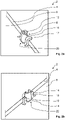
- 3a and 3b is a second embodiment of the assembly according to the invention for an induction hob shown purely as an example, the second embodiment in the image plane of 1 is shown above.
- the subassembly 2 for an induction hob comprises at least one induction coil 4 for inductive heating of a hotplate (also not shown) arranged on a cover plate of the induction hob, with the induction coil 4 in a 1 , 3a and 3b not shown assembled state of the assembly 2 is positioned on a support plate 6 and fixed.
- the induction coil 4 has coil form-locking means 8, 10 and the carrier plate 6 has carrier form-locking means 12, 14 designed to correspond to the coil form-locking means 8, 10, the induction coil 4 being positively locked by means of the coil form-locking means 8, 10 and the carrier form-locking means 12, 14 when the assembly 2 is in the assembled state is positioned and fixed on the support plate 6.
- the coil form-fitting means 8, 10 of the induction coil 4 are each formed as an edge of the induction coil 4 in the present exemplary embodiment.
- the induction coil 4 is therefore not specially designed to form the coil form-locking means 8, 10.
- the carrier form-locking means 12, 14 corresponding to the coil form-locking means 8, 10 are designed as a carrier form-locking means 12 designed as a carrier plate hook and, on the other hand, as a carrier form-locking means 14 designed as a carrier plate projection. See also the Figures 3a and 3b .
- the carrier positive-locking means 12 designed as a carrier plate hook encompass the coil positive-locking means 8, 10 designed as the edge of the induction coil 4, with the carrier positive-locking means 12, 14, in particular the carrier positive-locking means 12 designed as a carrier plate hook, being arranged in such a way that a connecting cable 15 of the aforesaid induction coil 4 acting on this induction coil 4 and prestressing the induction coil 4 perpendicularly to the carrier plate 6, lifting force can be accommodated by means of these carrier form-fitting means 12, 14, in particular the carrier form-fitting means 12.
- the induction coil 4 and the carrier plate 6 have, in addition to the above-mentioned form-fitting means 8, 10, 12, 14, other form-fitting means which correspond to one another.
- the induction coil 4 has two coil form-fitting means 16, 18 designed as so-called slugs 1 , 3a and 3b Not shown assembled state of the assembly 2 with corresponding and designed as openings in the support plate 6 carrier form-fitting means 20, 22 latchingly engaged.
- the module 2 is shown during its transfer into its assembled state.
- the coil form-locking means 16, 18 are designed as latching projections that engage in or on the carrier form-locking means 20, 22.
- the latching projections extend in the radial direction beyond the peripheral edge of the induction coil 4 .
- the latching projections are designed as hollow bodies, in particular as half hollow cylinders.
- coil form-fitting means 16, 18 and the corresponding carrier form-fitting means 20, 22 are designed to be coordinated with one another in such a way that these form-fitting means 16, 18, 20, 22 in the assembled state of the assembly 1 also form a force-fit connection, i.e. a friction-fit connection, in addition to a form-fit connection .
- the coil form-locking means 8, 10 and 16, 18 and the carrier form-locking means 12, 14 and 20, 22 corresponding to these coil form-locking means 8, 10, 16, 18 are each arranged on opposite sides of the induction coil 4.
- the carrier plate 6 with the carrier plate positive-locking means 12, 14 and 20, 22 and the induction coil 4 with the coil positive-locking means 8, 10 and 16, 18 are designed and arranged in such a way that the induction coil 4 is adapted for the purpose of transferring the assembly 2 in the assembled state can be positioned and fixed relative to the support plate 6 by means of a rotation about an axis of rotation 26, namely in such a way that the induction coil 4 can be positioned and fixed relative to the support plate 6 by means of a single rotation about this axis of rotation 26.
- the axis of rotation 26 runs perpendicularly to the carrier plate 6, that is to say perpendicularly to the plane of the image 1 .
- a fitter For the purpose of transferring the assembly 2 from a dismantled state to its assembled state, not shown, a fitter, not shown, places the support plate 6 as shown the 1 visible, on an assembly base, also not shown. The fitter then places the induction coil 4 with the coil form-fitting means 8 designed as the edge of the induction coil 4 on the carrier form-fitting means 12 designed as a carrier plate hook and with the coil form-fitting means 10 designed as the edge of the induction coil 4 on the carrier form-fitting means 14 designed as a carrier plate hook in such a way that the respective slugs trained coil form-fitting means 16, 18, as in the 1 , 3a and 3b shown, rest against the two carrier form-fitting means 12, 14.
- the fitter rotates the induction coil 4 in the image plane 1 clockwise around the axis of rotation 26, so that the coil form-locking means 8, 10, each designed as the edge of the induction coil 4, engage in a force-transmitting manner with the carrier form-locking means 12, 14, designed as carrier plate hooks.
- the induction coil 4 is parallel to the image plane of the present second embodiment 1 turned.
- the coil form-locking means 16, 18 designed as slugs engage with the carrier form-locking means 20, 22 designed as openings and latch with them.
- the mutually corresponding coil form-fitting means 16, 18 and carrier form-fitting means 20, 22 are designed in such a way that the induction coil 4 is positioned and fixed relative to the carrier plate 6 in the assembled state of the assembly 2 in addition to the respective form-fitting by force-fitting.
- the carrier plate 6 and the induction coil 4 according to the second exemplary embodiment are also designed for a multiple form-fitting of mutually corresponding carrier form-fitting means 12, 14 and 20, 22 and coil form-fitting means 8, 10 and 16, 18.
- this third embodiment differs more from the first and the second embodiment.
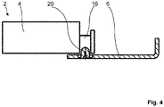
- the at least one carrier form-fitting means 20 and the corresponding coil form-fitting means 16 are embodied as a depression and a latching projection, with the coil form-fitting means 16 embodied as a depression being embodied as an opening and the carrier form-fitting means 20 embodied as a latching projection as an embossing.
- the coil form-locking means 16 can be designed for this purpose, for example as a slug forming the aforementioned opening, analogously to the two aforementioned exemplary embodiments.
- the aforementioned embossing can be known to those skilled in the way from the Support plate 6 be formed.
- the mutually corresponding coil form-locking means and carrier form-locking means 16, 20 are designed in the present embodiment such that the induction coil 4 in the 4 illustrated assembly state of the assembly 2 is positioned and fixed in addition to the form-fitting connection by friction between the coil form-fitting means 16 and the corresponding carrier form-fitting means 20.
- the at least one coil form-fitting means and the at least one carrier form-fitting means can be designed as a plurality of mutually corresponding form-fitting means of the induction coil 4 and the carrier plate 6 .
- the form-fitting means that correspond to one another can be arranged on two opposite sides of the induction coil 4 or evenly distributed over the circumference of the induction coil 4 .
- the assembly of an assembly 2 for an induction hob and thus the production of an induction hob equipped with it is significantly easier. Additional fasteners are not required to position and fix the at least one induction coil 4 relative to the support plate 6 during manufacture of the induction hob according to the invention, in order to then mount the cover plate of the induction hob. Furthermore, this enables savings in components and production steps. In addition, logistics and warehousing are simplified accordingly.
Landscapes
- Physics & Mathematics (AREA)
- Electromagnetism (AREA)
- General Induction Heating (AREA)
Abstract
Description
- Die Erfindung betrifft eine Baugruppe für ein Induktionskochfeld der im Oberbegriff des Patentanspruchs 1 genannten Art und ein Induktionskochfeld der im Oberbegriff des Patentanspruchs 10 genannten Art.
- Derartige Baugruppen für Induktionskochfelder und Induktionskochfelder sind aus dem Stand der Technik in einer Vielzahl von voneinander verschiedenen Bauformen bereits vorbekannt. Die bekannten Baugruppen für Induktionskochfelder umfassen dabei mindestens eine Induktionsspule zur induktiven Beheizung einer auf einer Deckplatte des Induktionskochfelds angeordneten Kochstelle, wobei die Induktionsspule in einem Montagezustand der Baugruppe auf einer Trägerplatte der Baugruppe positioniert und fixiert ist.
- Der Erfindung stellt sich somit das Problem, eine Baugruppe für ein Induktionskochfeld und ein Induktionskochfeld zu verbessern.
- Erfindungsgemäß wird dieses Problem durch eine Baugruppe für ein Induktionskochfeld mit den Merkmalen des Patentanspruchs 1 gelöst. Ferner wird dieses Problem durch ein Induktionskochfeld mit den Merkmalen des Patentanspruchs 10 gelöst. Bei den erfindungsgemäßen Induktionskochfeldern kann es sich beispielsweise um Einbaukochfelder handeln. Ferner können die erfindungsgemäßen Induktionskochfelder als Haushaltsgeräte oder als gewerbliche Geräte, also Kochfelder für den professionellen Bereich, ausgebildet sein. Vorteilhafte Ausgestaltungen und Weiterbildungen der Erfindung ergeben sich aus den nachfolgenden abhängigen Ansprüchen.
- Der mit der Erfindung erreichbare Vorteil besteht insbesondere darin, dass eine Baugruppe für ein Induktionskochfeld und ein Induktionskochfeld verbessert ist. Aufgrund der erfindungsgemäßen Ausbildung der Baugruppe für ein Induktionskochfeld und des Induktionskochfelds ist die Montage einer Baugruppe für ein Induktionskochfeld und damit die Herstellung eines damit ausgestatteten Induktionskochfelds wesentlich erleichtert. Zusätzliche Befestigungsmittel sind nicht erforderlich, um die mindestens eine Induktionsspule bei der Herstellung des erfindungsgemäßen Induktionskochfelds relativ zu der Trägerplatte zu positionieren und zu fixieren, um anschließend die Deckplatte des Induktionskochfelds zu montieren. Ferner ist dadurch eine Einsparung an Bauteilen und Fertigungsschritten ermöglicht. Auch die Bauhöhe des Spulenelements kann gegenüber dem Stand der Technik reduziert werden. Dadurch und darüber hinaus vereinfacht sich die Logistik und die Lagerhaltung entsprechend.
- Die erfindungsgemäße Baugruppe für ein Induktionskochfeld ist nach Art, Funktionsweise, Material, Dimensionierung und Anordnung in weiten geeigneten Grenzen frei wählbar. Siehe hierzu auch die obigen Ausführungen zu der Ausbildung des erfindungsgemäßen Induktionskochfelds.
- Eine vorteilhafte Weiterbildung der erfindungsgemäßen Baugruppe für ein Induktionskochfeld sieht vor, dass mindestens eines der Trägerformschlussmittel als eine Vertiefung oder als ein Rastvorsprung und das dazu korrespondierende Spulenformschlussmittel als ein Rastvorsprung ausgebildet sind, bevorzugt, dass die Vertiefung als eine Öffnung und/oder der Rastvorsprung als eine Verprägung ausgebildet sind/ist. Auf diese Weise ist dieses Trägerformschlussmittel und dieses dazu korrespondierende Spulenformschlussmittel auf konstruktiv besonders einfache und robuste Art ausgebildet. Ferner ist bei derartigen Formschlussmitteln neben einem Formschluss auch ein Kraftschluss, also ein Reibschluss, zur kraftübertragenden Verbindung zwischen der Induktionsspule auf der einen Seite und der Trägerplatte auf der anderen Seite ohne zusätzliche Bauteile einfach realisierbar. Entsprechend lassen sich mit den vorgenannten Formschlussmitteln noch größere Kräfte zwischen der Induktionsspule und der Trägerplatte übertragen.
- Ein Aspekt ist es, dass die Spulenformschlussmittel als in oder an die Trägerformschlussmittel einrastende Rastvorsprünge ausgebildet sind. Die Rastvorsprünge erstrecken sich dazu in radialer Richtung über die umlaufende Kante der Induktionsspule hinaus. Gemäß einer Weiterbildung sind die Rastvorsprünge als Hohlkörper, insbesondere als halbe Hohlzylinder, ausgebildet.
- Gemäß einer alternativen oder zusätzlichen Ausführungsform können die Rastvorsprünge auch über die Unterseite der Induktionsspule hinaus erstreckt sein, wobei die Unterseite der Induktionsspule die Seite ist, welche im montierten Zustand der Induktionsspule der Trägerplatte zugewandt ist. Im Montagezustand würde ein solcher Rastvorsprung dann in eine Durchbrechung der Trägerplatte eingreifen, welche im Bereich eines Trägerformschlussmittels ausgebildet ist. Wobei die Rastvorsprünge insbesondere als Hohlkörper, beispielsweise als halbe Hohlzylinder, ausgebildet sind.
- Eine weitere vorteilhafte Weiterbildung der erfindungsgemäßen Baugruppe für ein Induktionskochfeld sieht vor, dass mindestens eines der Trägerformschlussmittel als ein Trägerplattenhaken ausgebildet ist, wobei der Trägerplattenhaken das als ein Rand der jeweils korrespondierenden Induktionsspule ausgebildeten Spulenformschlussmittel in dem Montagezustand der Baugruppe umgreift, bevorzugt, dass mindestens eines des mindestens einen als Trägerplattenhaken ausgebildeten Trägerformschlussmittel derart angeordnet ist, dass eine durch ein Anschlusskabel der vorgenannten Induktionsspule auf diese Induktionsspule einwirkende, die Induktionsspule senkrecht zur Trägerplatte vorspannende Abhebekraft mittels dieses Trägerplattenhakens aufnehmbar ist. Hierdurch ist zum einen eine robuste und hohe Kräfte übertragende Formschlussverbindung zwischen der Induktionsspule und der Trägerplatte verwirklicht, wobei die Induktionsspule mittels des mindestens einen Trägerplattenhakens auf konstruktiv einfache Weise in zwei Raumrichtungen positionierbar und fixierbar ist. Darüber hinaus ist das dazu korrespondierende Spulenformschlussmittel auf konstruktiv besonders einfache Art realisiert, wobei keine Abänderung der Induktionsspule zur Ausbildung dieses Spulenformschlussmittels notwendig ist. Besonders vorteilhaft ist dabei die bevorzugte Ausführungsform dieser Weiterbildung, da insbesondere durch das Anschlusskabel der Induktionsspule ungewünschte Kräfte in die Baugruppe eingeleitet werden, die zu einer Vorspannung der Induktionsspule senkrecht zu der Trägerplatte führen.
- Eine besonders vorteilhafte Weiterbildung der erfindungsgemäßen Baugruppe für ein Induktionskochfeld sieht vor, dass die Spulenformschlussmittel und die zu diesen Spulenformschlussmitteln korrespondierenden Trägerformschlussmittel zumindest teilweise an einander gegenüberliegend angeordneten Seiten der Induktionsspule angeordnet sind. Auf diese Weise ist eine Positionierung und Fixierung der Induktionsspule relativ zu der Trägerplatte über die gesamte Ausdehnung der Induktionsspule auf konstruktiv und fertigungstechnisch besonders einfache Art ermöglicht.
- Erfindungsgemäß ist vorgesehen, dass die Trägerplatte mit den
- Trägerplattenformschlussmitteln und die Induktionsspule mit den Spulenformschlussmitteln derart aufeinander abgestimmt ausgebildet und angeordnet sind, dass die Induktionsspule zwecks Überführung der Baugruppe in deren Montagezustand mittels einer Drehung um eine Drehachse relativ zu der Trägerplatte positionierbar und fixierbar ist, bevorzugt, dass die Induktionsspule mittels einer einzigen Drehung um diese Drehachse relativ zu der Trägerplatte positionierbar und fixierbar ist. Hierdurch ist die Überführung der erfindungsgemäßen Baugruppe für ein Induktionskochfeld in deren Montagezustand von der Handhabung wesentlich vereinfacht.
- Dabei ist es möglich, dass die Drehachse parallel zu der Trägerplatte verläuft, wobei das mindestens eine drehachsenseitig angeordnete Trägerformschlussmittel als ein Trägerplattenhaken und das dazu korrespondierende Spulenformschlussmittel als ein der Drehachse zugewandter Rand der Induktionsspule ausgebildet sind, und wobei das mindestens eine drehachsenfern angeordnete Trägerformschlussmittel als ein senkrecht zu der Trägerplatte verlaufender Trägerplattenvorsprung und das dazu korrespondierende Spulenformschlussmittel als ein der Drehachse abgewandter Rand der Induktionsspule ausgebildet sind. Auf diese Weise ist die Handhabung bei der Überführung der erfindungsgemäßen Baugruppe in deren Montagezustand sehr einfach gestaltet, so dass die Ergonomie in der Fertigung des Induktionskochfelds zusätzlich verbessert ist.
- Dabei ist es alternativ möglich, dass die Drehachse senkrecht zu der Trägerplatte verläuft, wobei die mindestens zwei jeweils an gegenüberliegenden Seiten der Induktionsspule angeordneten Trägerformschlussmittel als Trägerplattenhaken und das jeweils korrespondierende Spulenformschlussmittel als ein Rand der Induktionsspule ausgebildet sind. Hierdurch ist eine zu der vorgenannten Ausführungsform ergonomisch gleichwertige Alternative zur Überführung der erfindungsgemäßen Baugruppe in deren Montagezustand angegeben. Darüber hinaus hat diese Weiterbildung den weiteren Vorteil, dass die Trägerplatte die Induktionsspule in dem Montagezustand der Baugruppe beidseitig, also an beiden einander gegenüberliegenden Seiten der Induktionsspule, umgreift.
- Eine weitere besonders vorteilhafte Weiterbildung der erfindungsgemäßen Baugruppe für ein Induktionskochfeld sieht vor, dass die Trägerplatte und die Induktionsspule für einen mehrfachen Formschluss von zueinander korrespondierenden Trägerformschlussmitteln und Spulenformschlussmitteln ausgebildet sind. Auf diese Weise ist die formschlüssige Verbindung zwischen der Induktionsspule auf der einen Seite und der Trägerplatte auf der anderen Seite in dem Montagezustand der Baugruppe weiter verbessert. Entsprechend ist beispielsweise eine Positionierung und Fixierung der Induktionsspule relativ zu der Trägerplatte in mehrere Raumrichtungen auf konstruktiv und fertigungstechnisch einfache Art ermöglicht. Beispielsweise können die einzelnen Trägerformschlussmittel und Spulenformschlussmittel in Verbindung mit der Trägerplatte und der Induktionsspule derart aufeinander abgestimmt ausgebildet sein, dass sich die jeweiligen Paarungen zueinander korrespondierender Trägerformschlussmittel und Spulenformschlussmittel bei der Überführung der erfindungsgemäßen Baugruppe in deren Montagezustand und/oder in deren Montagezustand in deren Wirkung untereinander ergänzen, so dass sich bei der Überführung der erfindungsgemäßen Baugruppe in deren Montagezustand und/oder in deren Montagezustand eine kombinierte Wirkung zumindest eines Teils der vorgenannten Paarungen von Formschlussmitteln ergibt.
- Eine andere vorteilhafte Weiterbildung der erfindungsgemäßen Baugruppe für ein Induktionskochfeld sieht vor, dass die zueinander korrespondierenden Trägerformschlussmittel und Spulenformschlussmittel zumindest teilweise derart aufeinander abgestimmt ausgebildet sind, dass die Induktionsspule in dem Montagezustand der Baugruppe zusätzlich durch Kraftschluss, also durch Reibschluss, zwischen mindestens einem Trägerformschlussmittel und dem dazu korrespondierenden Spulenformschlussmittel positioniert und fixiert ist. Hierdurch ist mit einfachen Mitteln eine noch höhere Kraftübertragung zwischen der Induktionsspule und der Trägerplatte realisierbar.
- Drei Ausführungsbeispiele der Erfindung sind in den Zeichnungen rein schematisch dargestellt und werden nachfolgend näher beschrieben. Es zeigt
- Figur 1
- ein erstes und ein zweites Ausführungsbeispiel der erfindungsgemäßen Baugruppe für ein Induktionskochfeld in einer gemeinsamen Draufsicht, in jeweils teilweiser Darstellung,
- Figur 2a, b
- das erste Ausführungsbeispiel in zwei teilweisen, perspektivischen Detaildarstellungen im Bereich der zueinander korrespondierenden Formschlussmittel,
- Figur 3a, b
- das zweite Ausführungsbeispiel in zwei teilweisen, perspektivischen Detaildarstellungen im Bereich der zueinander korrespondierenden Formschlussmittel und
- Figur 4
- ein drittes Ausführungsbeispiel der erfindungsgemäßen Baugruppe für ein Induktionskochfeld in einer Seitenansicht.
- In den
Fig. 1 bis 2b ist ein erstes Ausführungsbeispiel der erfindungsgemäßen Baugruppe für ein Induktionskochfeld rein exemplarisch dargestellt, wobei das erste Ausführungsbeispiel in der Bildebene derFig. 1 unten gezeigt ist. - Die Baugruppe 2 für ein nicht näher dargestelltes Induktionskochfeld umfasst mindestens eine Induktionsspule 4 zur induktiven Beheizung einer auf einer nicht dargestellten Deckplatte des Induktionskochfelds angeordneten, ebenfalls nicht dargestellten Kochstelle, wobei die Induktionsspule 4 in einem in der
Fig. 1 dargestellten Montagezustand der Baugruppe 2 auf einer Trägerplatte 6 der Baugruppe 2 positioniert und fixiert ist. - Die Induktionsspule 4 weist Spulenformschlussmittel 8, 10 und die Trägerplatte 6 weist zu den Spulenformschlussmitteln 8, 10 korrespondierend ausgebildete Trägerformschlussmittel 12, 14 auf, wobei die Induktionsspule 4 mittels der Spulenformschlussmittel 8, 10 und der Trägerformschlussmittel 12, 14 in dem Montagezustand der Baugruppe 2 formschlüssig an der Trägerplatte 6 positioniert und fixiert ist.
- Die Spulenformschlussmittel 8, 10 der Induktionsspule 4 sind bei dem vorliegenden Ausführungsbeispiel jeweils als ein Rand der Induktionsspule 4 ausgebildet. Die Induktionsspule 4 ist somit nicht speziell hergerichtet, um die Spulenformschlussmittel 8, 10 auszubilden.
- Die zu den Spulenformschlussmitteln 8, 10 korrespondierenden Trägerformschlussmittel 12, 14 sind bei dem vorliegenden Ausführungsbeispiel zum einen als zwei parallel zueinander angeordnete Trägerplattenhaken ausgebildete Trägerformschlussmittel 12 und zum anderen als zwei senkrecht zu der Trägerplatte 6 und parallel zueinander verlaufende Trägerplattenvorsprünge ausgebildete Trägerformschlussmittel 14 ausgeführt. Siehe hierzu auch die
Fig. 2a und 2b . Das als Trägerplattenhaken ausgebildete Trägerformschlussmittel 12 umgreift in dem Montagezustand der Baugruppe 2 das als Rand der Induktionsspule 4 ausgebildete Spulenformschlussmittel 8, wobei das als Trägerplattenhaken ausgebildete Trägerformschlussmittel 12 derart angeordnet ist, dass eine durch ein Anschlusskabel 15 der vorgenannten Induktionsspule 4 auf diese Induktionsspule 4 einwirkende, die Induktionsspule 4 senkrecht zur Trägerplatte 6 vorspannende, Abhebekraft mittels dieses Trägerformschlussmittels 12 aufnehmbar ist. - Wie insbesondere aus den
Fig. 2a und 2b ersichtlich ist, weisen die Induktionsspule 4 und die Trägerplatte 6 zusätzlich zu den vorgenannten Formschlussmitteln 8, 10, 12, 14 weitere zueinander korrespondierende Formschlussmittel auf. - Zum einen weist die Induktionsspule 4 zwei als sogenannte Butzen ausgebildete Spulenformschlussmittel 16, 18 auf, die in dem in den
Fig. 1 bis 2b dargestellten Montagezustand der Baugruppe 2 mit dazu korrespondierenden und als Öffnungen in der Trägerplatte 6 ausgebildeten Trägerformschlussmitteln 20, 22 rastend in Eingriff sind. Die Spulenformschlussmittel 16, 18 sind bei dem vorliegenden Ausführungsbeispiel entweder als in oder an die Trägerformschlussmittel 20, 22 einrastende Rastvorsprünge. Die Rastvorsprünge erstrecken sich dazu in radialer Richtung über die umlaufende Kante der Induktionsspule 4 hinaus. Gemäß einer Weiterbildung sind die Rastvorsprünge als Hohlkörper, insbesondere als halbe Hohlzylinder, ausgebildet. - Zusätzlich sind die Spulenformschlussmittel 16, 18 und die dazu korrespondierenden Trägerformschlussmittel 20, 22 derart aufeinander abgestimmt ausgebildet, dass diese Formschlussmittel 16, 18, 20, 22 in dem Montagezustand der Baugruppe 2 zusätzlich zu einer Formschlussverbindung jeweils auch eine Kraftschlussverbindung, also eine Reibschlussverbindung, ausbilden.
- Wie aus der
Fig. 1 entnehmbar ist, sind die Spulenformschlussmittel 8, 10 sowie 16, 18 und die zu diesen Spulenformschlussmitteln 8, 10, 16, 18 korrespondierenden Trägerformschlussmittel 12, 14 sowie 20, 22 jeweils an einander gegenüberliegend angeordneten Seiten der Induktionsspule 4 angeordnet. - Wie nachfolgend noch näher erläutert wird, sind die Trägerplatte 6 mit den Trägerplattenformschlussmitteln 12, 14 sowie 20, 22 und die Induktionsspule 4 mit den Spulenformschlussmitteln 8, 10 sowie 16, 18 derart aufeinander abgestimmt ausgebildet und angeordnet, dass die Induktionsspule 4 zwecks Überführung der Baugruppe 2 in deren Montagezustand mittels einer Drehung um eine Drehachse 24 relativ zu der Trägerplatte 6 positionierbar und fixierbar ist, nämlich derart, dass die Induktionsspule 4 mittels einer einzigen Drehung um diese Drehachse 24 relativ zu der Trägerplatte 6 positionierbar und fixierbar ist. Die Drehachse 24 verläuft bei dem vorliegenden Ausführungsbeispiel parallel zu der Trägerplatte 6, wobei die als Trägerplattenhaken ausgebildeten Trägerformschlussmittel 12 drehachsenseitig und die als Trägerplattenvorsprünge ausgebildeten Trägerformschlussmittel 14 drehachsenfern angeordnet sind.
- Nachfolgend wird die Funktionsweise der erfindungsgemäßen Baugruppe für ein Induktionskochfeld gemäß dem ersten Ausführungsbeispiel anhand der
Fig. 1 bis 2b erläutert. - Zwecks Überführung der Baugruppe 2 von einem nicht dargestellten Demontagezustand in den in den
Fig. 1 bis 2b dargestellten Montagezustand legt ein nicht dargestellter Monteur die Trägerplatte 6, wie aus derFig. 1 ersichtlich, auf einer ebenfalls nicht dargestellten Montageunterlage ab. Anschließend setzt der Monteur die Induktionsspule 4 mit dem in derFig. 1 links dargestellten und als Rand der Induktionsspule 4 ausgebildeten Spulenformschlussmittel 8 an den beiden als Trägerplattenhaken ausgebildeten Trägerformschlussmitteln 12 derart schräg an, dass das als Butzen ausgebildete Spulenformschlussmittel 16 zwischen den beiden Trägerformschlussmitteln 12 eingreift. Danach dreht der Monteur die Induktionsspule 4 um die Drehachse 24 in Richtung der Bildebene derFig. 1 , so dass das als Rand der Induktionsspule 4 ausgebildete Spulenformschlussmittel 10 mit den als Trägerplattenvorsprünge ausgebildeten Trägerformschlussmitteln 14, wie aus denFig. 1 und2b ersichtlich, derart in Eingriff gelangt, dass sich das als Butzen ausgebildete Spulenformschlussmittel 18 zwischen den beiden Trägerformschlussmitteln 14 befindet. Gleichzeitig gelangen die als Butzen ausgebildeten Spulenformschlussmittel 16, 18 bei der vorgenannten Drehung der Induktionsspule 4 um die Drehachse 24 in Eingriff mit den als Öffnungen ausgebildeten Trägerformschlussmitteln 20, 22 und verrasten mit diesen. Dabei sind die zueinander korrespondierenden Spulenformschlussmittel 16, 18 und Trägerformschlussmittel 20, 22 derart ausgebildet, dass die Induktionsspule 4 in dem Montagezustand der Baugruppe 2 zusätzlich zum jeweiligen Formschluss durch Kraftschluss relativ zu der Trägerplatte 6 positioniert und fixiert ist. - Wie aus den obigen Ausführungen deutlich wird, sind die Trägerplatte 6 und die Induktionsspule 4 somit für einen mehrfachen Formschluss von zueinander korrespondierenden Trägerformschlussmitteln 12, 14 sowie 20, 22 und Spulenformschlussmitteln 8, 10 sowie 16, 18 ausgebildet.
- Im Nachfolgenden werden ein zweites und ein drittes Ausführungsbeispiel der erfindungsgemäßen Baugruppe für ein Induktionskochfeld exemplarisch erläutert. Gleiche oder gleichwirkende Bauteile sind mit gleichen Bezugszeichen bezeichnet. Ferner werden die weiteren Ausführungsbeispiele lediglich im Umfang der Unterscheidungsmerkmale zu den vorgenannten Ausführungsbeispielen erläutert. Ansonsten wird auf die Ausführungen zu den vorhergehenden Ausführungsbeispielen verwiesen. Darüber hinaus sind auch beliebige und geeignete Kombinationen der erläuterten Ausführungsbeispiele untereinander sowie mit anderen denkbaren Formschlussverbindungen der mindestens einen Induktionsspule und der Trägerplatte der erfindungsgemäßen Baugruppe möglich.
- In den
Fig. 1 ,3a und 3b ist ein zweites Ausführungsbeispiel der erfindungsgemäßen Baugruppe für ein Induktionskochfeld rein exemplarisch dargestellt, wobei das zweite Ausführungsbeispiel in der Bildebene derFig. 1 oben gezeigt ist. - Die Baugruppe 2 für ein nicht näher dargestelltes Induktionskochfeld gemäß dem vorliegenden zweiten Ausführungsbeispiel umfasst mindestens eine Induktionsspule 4 zur induktiven Beheizung einer auf einer nicht dargestellten Deckplatte des Induktionskochfelds angeordneten, ebenfalls nicht dargestellten Kochstelle, wobei die Induktionsspule 4 in einem in den
Fig. 1 ,3a und 3b nicht dargestellten Montagezustand der Baugruppe 2 auf einer Trägerplatte 6 positioniert und fixiert ist. - Die Induktionsspule 4 weist Spulenformschlussmittel 8, 10 und die Trägerplatte 6 weist zu den Spulenformschlussmitteln 8, 10 korrespondierend ausgebildete Trägerformschlussmittel 12, 14 auf, wobei die Induktionsspule 4 mittels der Spulenformschlussmittel 8, 10 und der Trägerformschlussmittel 12, 14 in dem Montagezustand der Baugruppe 2 formschlüssig an der Trägerplatte 6 positioniert und fixiert ist.
- Die Spulenformschlussmittel 8, 10 der Induktionsspule 4 sind bei dem vorliegenden Ausführungsbeispiel jeweils als ein Rand der Induktionsspule 4 ausgebildet. Die Induktionsspule 4 ist somit nicht speziell hergerichtet, um die Spulenformschlussmittel 8, 10 auszubilden.
- Die zu den Spulenformschlussmitteln 8, 10 korrespondierenden Trägerformschlussmittel 12, 14 sind bei dem vorliegenden Ausführungsbeispiel zum einen als ein als Trägerplattenhaken ausgebildetes Trägerformschlussmittel 12 und zum anderen als ein als Trägerplattenvorsprung ausgebildetes Trägerformschlussmittel 14 ausgeführt. Siehe hierzu auch die
Fig. 3a und 3b . Die als Trägerplattenhaken ausgebildeten Trägerformschlussmittel 12 umgreifen in dem Montagezustand der Baugruppe 2 die als Rand der Induktionsspule 4 ausgebildeten Spulenformschlussmittel 8, 10, wobei die Trägerformschlussmittel 12, 14, insbesondere das als Trägerplattenhaken ausgebildete Trägerformschlussmittel 12, derart angeordnet sind, dass eine durch ein Anschlusskabel 15 der vorgenannten Induktionsspule 4 auf diese Induktionsspule 4 einwirkende, die Induktionsspule 4 senkrecht zur Trägerplatte 6 vorspannende, Abhebekraft mittels dieser Trägerformschlussmittel 12, 14, insbesondere dem Trägerformschlussmittel 12, aufnehmbar ist. - Wie insbesondere aus den
Fig. 3a und 3b ersichtlich ist, weisen die Induktionsspule 4 und die Trägerplatte 6 zusätzlich zu den vorgenannten Formschlussmitteln 8, 10, 12, 14 weitere zueinander korrespondierende Formschlussmittel auf. - Zum einen weist die Induktionsspule 4 zwei als sogenannte Butzen ausgebildete Spulenformschlussmittel 16, 18 auf, die in dem in den
Fig. 1 ,3a und 3b nicht dargestellten Montagezustand der Baugruppe 2 mit dazu korrespondierenden und als Öffnungen in der Trägerplatte 6 ausgebildeten Trägerformschlussmitteln 20, 22 rastend in Eingriff sind. In denFig. 3a und 3b ist die Baugruppe 2 gerade bei deren Überführung in deren Montagezustand gezeigt. Die Spulenformschlussmittel 16, 18 sind bei dem vorliegenden Ausführungsbeispiel als in oder an die Trägerformschlussmittel 20, 22 einrastende Rastvorsprünge ausgebildet. Die Rastvorsprünge erstrecken sich dazu in radialer Richtung über die umlaufende Kante der Induktionsspule 4 hinaus. Gemäß einer Weiterbildung sind die Rastvorsprünge, nämlich als Hohlkörper, insbesondere als halbe Hohlzylinder, ausgebildet. Zusätzlich sind die Spulenformschlussmittel 16, 18 und die dazu korrespondierenden Trägerformschlussmittel 20, 22 derart aufeinander abgestimmt ausgebildet, dass diese Formschlussmittel 16, 18, 20, 22 in dem Montagezustand der Baugruppe 1 zusätzlich zu einer Formschlussverbindung jeweils auch eine Kraftschlussverbindung, also eine Reibschlussverbindung, ausbilden. - Wie aus der
Fig. 1 entnehmbar ist, sind die Spulenformschlussmittel 8, 10 sowie 16, 18 und die zu diesen Spulenformschlussmitteln 8, 10, 16, 18 korrespondierenden Trägerformschlussmittel 12, 14 sowie 20, 22 jeweils an einander gegenüberliegend angeordneten Seiten der Induktionsspule 4 angeordnet. - Wie nachfolgend noch näher erläutert wird, sind die Trägerplatte 6 mit den Trägerplattenformschlussmitteln 12, 14 sowie 20, 22 und die Induktionsspule 4 mit den Spulenformschlussmitteln 8, 10 sowie 16, 18 derart aufeinander abgestimmt ausgebildet und angeordnet, dass die Induktionsspule 4 zwecks Überführung der Baugruppe 2 in deren Montagezustand mittels einer Drehung um eine Drehachse 26 relativ zu der Trägerplatte 6 positionierbar und fixierbar ist, nämlich derart, dass die Induktionsspule 4 mittels einer einzigen Drehung um diese Drehachse 26 relativ zu der Trägerplatte 6 positionierbar und fixierbar ist. Die Drehachse 26 verläuft bei dem vorliegenden Ausführungsbeispiel senkrecht zu der Trägerplatte 6, also senkrecht zu der Bildebene der
Fig. 1 . - Nachfolgend wird die Funktionsweise der erfindungsgemäßen Baugruppe für ein Induktionskochfeld gemäß dem zweiten Ausführungsbeispiel anhand der
Fig. 1 ,3a und 3b erläutert. - Zwecks Überführung der Baugruppe 2 von einem Demontagezustand in deren nicht dargestellten Montagezustand legt ein nicht dargestellter Monteur die Trägerplatte 6, wie aus der
Fig. 1 ersichtlich, auf einer ebenfalls nicht dargestellten Montageunterlage ab. Anschließend setzt der Monteur die Induktionsspule 4 mit dem als Rand der Induktionsspule 4 ausgebildeten Spulenformschlussmittel 8 an das als Trägerplattenhaken ausgebildete Trägerformschlussmittel 12 und mit dem als Rand der Induktionsspule 4 ausgebildeten Spulenformschlussmittel 10 an das als Trägerplattenhaken ausgebildete Trägerformschlussmittel 14 derart an, dass die jeweils als Butzen ausgebildeten Spulenformschlussmittel 16, 18, wie in denFig. 1 ,3a und 3b dargestellt, an den beiden Trägerformschlussmitteln 12, 14 anliegen. Danach dreht der Monteur die Induktionsspule 4 in der Bildebene derFig. 1 im Uhrzeigersinn um die Drehachse 26, so dass die jeweils als Rand der Induktionsspule 4 ausgebildeten Spulenformschlussmittel 8, 10 mit den als Trägerplattenhaken ausgebildeten Trägerformschlussmitteln 12, 14 kraftübertragend in Eingriff gelangen. Im Unterschied zu dem ersten Ausführungsbeispiel wird die Induktionsspule 4 bei dem vorliegenden zweiten Ausführungsbeispiel also parallel zu der Bildebene derFig. 1 gedreht. Gleichzeitig gelangen die als Butzen ausgebildeten Spulenformschlussmittel 16, 18 bei der vorgenannten Drehung der Induktionsspule 4 um die Drehachse 26 in Eingriff mit den als Öffnungen ausgebildeten Trägerformschlussmitteln 20, 22 und verrasten mit diesen. Dabei sind die zueinander korrespondierenden Spulenformschlussmittel 16, 18 und Trägerformschlussmittel 20, 22 derart ausgebildet, dass die Induktionsspule 4 in dem Montagezustand der Baugruppe 2 zusätzlich zum jeweiligen Formschluss durch Kraftschluss relativ zu der Trägerplatte 6 positioniert und fixiert ist. - Wie aus den obigen Ausführungen deutlich wird, sind die Trägerplatte 6 und die Induktionsspule 4 gemäß dem zweiten Ausführungsbeispiel ebenfalls für einen mehrfachen Formschluss von zueinander korrespondierenden Trägerformschlussmitteln 12, 14 sowie 20, 22 und Spulenformschlussmitteln 8, 10 sowie 16, 18 ausgebildet.
- Schließlich ist in der
Fig. 4 ein drittes Ausführungsbeispiel der erfindungsgemäßen Baugruppe für ein Induktionskochfeld exemplarisch gezeigt, wobei sich dieses dritte Ausführungsbeispiel stärker von dem ersten und dem zweiten Ausführungsbeispiel unterscheidet. - Bei dem dritten Ausführungsbeispiel sind das mindestens eine Trägerformschlussmittel 20 und das dazu korrespondierende Spulenformschlussmittel 16 als eine Vertiefung und ein Rastvorsprung ausgebildet, wobei das als Vertiefung ausgebildete Spulenformschlussmittel 16 als eine Öffnung und das als Rastvorsprung ausgebildete Trägerformschlussmittel 20 als eine Verprägung ausgebildet sind. Wie aus der
Fig. 4 ersichtlich ist, kann das Spulenformschlussmittel 16 hierfür beispielsweise als eine die vorgenannte Öffnung ausformende Butze, analog zu den beiden vorgenannten Ausführungsbeispielen, ausgebildet sein. Die vorgenannte Verprägung kann auf dem Fachmann bekannte Art und Weise aus der Trägerplatte 6 ausgebildet sein. Die zueinander korrespondierenden Spulenformschlussmittel und Trägerformschlussmittel 16, 20 sind bei dem vorliegenden Ausführungsbeispiel derart ausgebildet, dass die Induktionsspule 4 in dem in derFig. 4 dargestellten Montagezustand der Baugruppe 2 neben der Formschlussverbindung zusätzlich durch Kraftschluss zwischen dem Spulenformschlussmittel 16 und dem dazu korrespondierenden Trägerformschlussmittel 20 positioniert und fixiert ist. Analog zu den beiden vorgenannten Ausführungsbeispielen ist es möglich, dass das mindestens eine Spulenformschlussmittel und das mindestens eine Trägerformschlussmittel jeweils als eine Mehrzahl von zueinander korrespondierenden Formschlussmitteln der Induktionsspule 4 und der Trägerplatte 6 ausgebildet sind. Beispielsweise können die zueinander korrespondierenden Formschlussmittel an zwei gegenüberliegenden Seiten der Induktionsspule 4 oder gleichmäßig über den Umfang der Induktionsspule 4 verteilt angeordnet sein. - Aufgrund der erfindungsgemäßen Ausbildung der Baugruppe für ein Induktionskochfeld und des Induktionskochfelds gemäß den vorliegenden drei Ausführungsbeispielen ist die Montage einer Baugruppe 2 für ein Induktionskochfeld und damit die Herstellung eines damit ausgestatteten Induktionskochfelds wesentlich erleichtert. Zusätzliche Befestigungsmittel sind nicht erforderlich, um die mindestens eine Induktionsspule 4 bei der Herstellung des erfindungsgemäßen Induktionskochfelds relativ zu der Trägerplatte 6 zu positionieren und zu fixieren, um anschließend die Deckplatte des Induktionskochfelds zu montieren. Ferner ist dadurch eine Einsparung an Bauteilen und Fertigungsschritten ermöglicht. Darüber hinaus vereinfacht sich die Logistik und die Lagerhaltung entsprechend.
- Die Erfindung ist nicht auf die erläuterten Ausführungsbeispiele beschränkt.
- Insbesondere gilt dies für die konstruktiven und fertigungstechnischen Details der vorgenannten Ausführungsbeispiele. Wie oben bereits ausgeführt, sind beispielsweise beliebige und geeignete Kombinationen der erläuterten Ausführungsbeispiele untereinander sowie mit anderen denkbaren Formschlussverbindungen der mindestens einen Induktionsspule und der Trägerplatte der erfindungsgemäßen Baugruppe möglich.
Claims (10)
- Baugruppe (2) für ein Induktionskochfeld, umfassendeine Trägerplatte (6) undmindestens eine Induktionsspule (4) zur induktiven Beheizung einer auf einer Deckplatte des Induktionskochfelds angeordneten Kochstelle,wobei die Induktionsspule (4) in einem Montagezustand der Baugruppe (2) auf der Trägerplatte (6) positioniert und fixiert ist,die Induktionsspule (4) Spulenformschlussmittel (8, 10, 16, 18) und die Trägerplatte (6) zu den Spulenformschlussmitteln (8, 10, 16, 18) korrespondierend ausgebildete Trägerformschlussmittel (12, 14, 20, 22) aufweisen,wobei die Induktionsspule (4) mittels der Spulenformschlussmittel (8, 10, 16, 18) und der Trägerformschlussmittel (12, 14, 20, 22) in dem Montagezustand der Baugruppe (2) formschlüssig an der Trägerplatte (6) positioniert und fixiert istwobei die Trägerplatte (6) mit den Trägerplattenformschlussmitteln (12, 14, 20, 22) und die Induktionsspule (4) mit den Spulenformschlussmitteln (8, 10, 16, 18) derart aufeinander abgestimmt ausgebildet und angeordnet sind, dass die Induktionsspule (4) zwecks Überführung der Baugruppe (2) in deren Montagezustand mittels einer Drehung um eine Drehachse (24; 26) relativ zu der Trägerplatte (6) positionierbar und fixierbar ist,dadurch gekennzeichnet, dassdie Trägerplattenformschlussmittel (12, 14, 20, 22) als eine Verprägung in der Trägerplatte (6) und auf einer Spulenseite der Trägerplatte (6) ausgeführt sind, wobei in einem Montagezustand die alle Induktionsspulen (4) auf der Spulenseite der Trägerplatte (6) angeordnet sind,und ein als Trägerplattenhaken ausgebildetes Trägerformschlussmittel (12, 14) in dem Montagezustand der Baugruppe (2) einen Rand der Induktionsspule (4) umgreiftund ein Trägerplattenvorsprung aus wenigstens einem Körper besteht, der senkrecht zu der Trägerplatte (6) erstreckt ist,wobei die Drehachse (24) parallel oder senkrecht zu der Trägerplatte (6) verläuft,wobei bei einer parallel zu der Trägerplatte (6) verlaufenden Drehachse (24)das mindestens eine drehachsenseitig angeordnete Trägerformschlussmittel (12) als ein Trägerplattenhaken und das dazu korrespondierende Spulenformschlussmittel (8) als ein der Drehachse (24) zugewandter Rand der Induktionsspule (4) ausgebildet sindund das mindestens eine drehachsenfern angeordnete Trägerformschlussmittel (14) als ein senkrecht zu der Trägerplatte (6) verlaufender Trägerplattenvorsprung und das dazu korrespondierende Spulenformschlussmittel (10) als ein der Drehachse (24) abgewandter Rand der Induktionsspule (4) ausgebildet sind,wobei bei einer senkrecht zu der Trägerplatte (6) verlaufenden Drehachse (24)
die mindestens zwei jeweils an gegenüberliegenden Seiten der Induktionsspule (4) angeordneten Trägerformschlussmittel (12, 14) als Trägerplattenhaken und das jeweils korrespondierende Spulenformschlussmittel (8, 10) als ein Rand der Induktionsspule (4) ausgebildet sind. - Baugruppe (2) nach Anspruch 1, wobei mindestens eines der Trägerformschlussmittel (20, 22) als ein Rastvorsprung und das dazu korrespondierende Spulenformschlussmittel (16, 18) als eine Vertiefung oder als ein Rastvorsprung ausgebildet sind, bevorzugt, dass die Vertiefung als eine Öffnung und/oder der Rastvorsprung als eine Verprägung ausgebildet sind/ist.
- Baugruppe (2) nach Anspruch 1 oder 2, wobei mindestens eines des mindestens einen als Trägerplattenhaken ausgebildeten Trägerformschlussmittel ( 12, 14) derart angeordnet ist, dass eine durch ein Anschlusskabel (15) der vorgenannten Induktionsspule (4) auf diese Induktionsspule (4) einwirkende, die Induktionsspule (4) senkrecht zur Trägerplatte (6) vorspannende, Abhebekraft mittels dieses Trägerplattenhakens aufnehmbar ist.
- Baugruppe (2) nach einem der vorhergehenden Ansprüche, wobei die Spulenformschlussmittel (8, 10, 16, 18) und die zu diesen Spulenformschlussmitteln (8, 10, 16, 18) korrespondierenden Trägerformschlussmittel (12, 14, 20, 22) zumindest teilweise an einander gegenüberliegend angeordneten Seiten der Induktionsspule (4) angeordnet sind.
- Baugruppe (2) nach einem der vorhergehenden Ansprüche, wobei die Induktionsspule (4) mittels einer einzigen Drehung um diese Drehachse (24; 26) relativ zu der Trägerplatte (6) positionierbar und fixierbar ist.
- Baugruppe (2) nach Anspruch 3, wobei insbesondere das als Trägerplattenhaken ausgebildete Trägerformschlussmittel (12, 14) zu dem Anschlusskabel (15) der montierten Induktionsspule (4) einen Abstand aufweist, wobei der Abstand entlang des Umfangs der Induktionsspule (4) gemessen weniger als ein Drittel des Umfangs der Induktionsspule (4) beträgt.
- Baugruppe (2) nach einem der vorhergehenden Ansprüche, wobei die Spulenformschlussmittel (8, 10, 16, 18) als in oder an die Trägerformschlussmittel (12, 14, 20, 22) einrastende Rastvorsprünge ausgebildet sind,wobei sich die Rastvorsprünge in radialer Richtung über die umlaufende Kante der Induktionsspule (4) hinaus erstrecken,
und/oderwobei die Rastvorsprünge über die Unterseite der Induktionsspule (4) hinaus erstreckt sind, wobei die Unterseite der Induktionsspule (4) die Seite ist, welche im montierten Zustand der Induktionsspule (4) der Trägerplatte (6) zugewandt ist, wobei im Montagezustand ein solcher Rastvorsprung in eine Durchbrechung der Trägerplatte (6) eingreift, welche im Bereich eines Trägerformschlussmittels (12, 14, 20, 22) ausgebildet ist. - Baugruppe (2) nach einem der vorhergehenden Ansprüche, wobei die Trägerplatte (6) und die Induktionsspule (4) für einen mehrfachen Formschluss von zueinander korrespondierenden Trägerformschlussmitteln (12, 14, 20, 22) und Spulenformschlussmitteln (8, 10, 16, 18) ausgebildet sind.
- Baugruppe (2) nach einem der vorhergehenden Ansprüche, wobei die zueinander korrespondierenden Trägerformschlussmittel (12, 14, 20, 22) und Spulenformschlussmittel (8, 10, 16, 18) zumindest teilweise derart aufeinander abgestimmt ausgebildet sind, dass die Induktionsspule (4) in dem Montagezustand der Baugruppe (2) zusätzlich durch Kraftschluss zwischen mindestens einem Trägerformschlussmittel (20, 22) und dem dazu korrespondierenden Spulenformschlussmittel (16, 18) positioniert und fixiert ist.
- Induktionskochfeld, umfassend eine Baugruppe (2) mit mindestens einer Induktionsspule (4) zur induktiven Beheizung einer auf einer Deckplatte des Induktionskochfelds angeordneten Kochstelle, wobei die Induktionsspule (4) in einem Montagezustand der Baugruppe (2) auf einer Trägerplatte (6) der Baugruppe (2) positioniert und fixiert ist, dadurch gekennzeichnet, dass die Baugruppe (2) nach einem der Ansprüche 1 bis 9 ausgebildet ist.
Applications Claiming Priority (1)
| Application Number | Priority Date | Filing Date | Title |
|---|---|---|---|
| DE102020125994.8A DE102020125994A1 (de) | 2020-10-05 | 2020-10-05 | Baugruppe für ein Induktionskochfeld und Induktionskochfeld |
Publications (3)
| Publication Number | Publication Date |
|---|---|
| EP3979769A1 true EP3979769A1 (de) | 2022-04-06 |
| EP3979769C0 EP3979769C0 (de) | 2025-11-05 |
| EP3979769B1 EP3979769B1 (de) | 2025-11-05 |
Family
ID=77838763
Family Applications (1)
| Application Number | Title | Priority Date | Filing Date |
|---|---|---|---|
| EP21197616.2A Active EP3979769B1 (de) | 2020-10-05 | 2021-09-20 | Baugruppe für ein induktionskochfeld und induktionskochfeld |
Country Status (2)
| Country | Link |
|---|---|
| EP (1) | EP3979769B1 (de) |
| DE (1) | DE102020125994A1 (de) |
Cited By (1)
| Publication number | Priority date | Publication date | Assignee | Title |
|---|---|---|---|---|
| US20230160499A1 (en) * | 2020-05-14 | 2023-05-25 | Miele & Cie. Kg | Holder element for flexible lines |
Citations (3)
| Publication number | Priority date | Publication date | Assignee | Title |
|---|---|---|---|---|
| US20160057815A1 (en) * | 2014-08-22 | 2016-02-25 | General Electric Company | Induction cooking appliance and method for assembling same |
| US20180168006A1 (en) * | 2016-12-13 | 2018-06-14 | Haier Us Appliance Solutions, Inc. | Induction cooking appliance and method of assembly |
| EP3052863B1 (de) * | 2013-10-03 | 2020-03-18 | BSH Hausgeräte GmbH | Kochfeldvorrichtung |
-
2020
- 2020-10-05 DE DE102020125994.8A patent/DE102020125994A1/de active Granted
-
2021
- 2021-09-20 EP EP21197616.2A patent/EP3979769B1/de active Active
Patent Citations (3)
| Publication number | Priority date | Publication date | Assignee | Title |
|---|---|---|---|---|
| EP3052863B1 (de) * | 2013-10-03 | 2020-03-18 | BSH Hausgeräte GmbH | Kochfeldvorrichtung |
| US20160057815A1 (en) * | 2014-08-22 | 2016-02-25 | General Electric Company | Induction cooking appliance and method for assembling same |
| US20180168006A1 (en) * | 2016-12-13 | 2018-06-14 | Haier Us Appliance Solutions, Inc. | Induction cooking appliance and method of assembly |
Cited By (1)
| Publication number | Priority date | Publication date | Assignee | Title |
|---|---|---|---|---|
| US20230160499A1 (en) * | 2020-05-14 | 2023-05-25 | Miele & Cie. Kg | Holder element for flexible lines |
Also Published As
| Publication number | Publication date |
|---|---|
| EP3979769C0 (de) | 2025-11-05 |
| EP3979769B1 (de) | 2025-11-05 |
| DE102020125994A1 (de) | 2022-04-07 |
Similar Documents
| Publication | Publication Date | Title |
|---|---|---|
| EP2655835B1 (de) | Ventileinheit | |
| DE2855399A1 (de) | Drehschwingungsdaempfer | |
| DE102015211748B4 (de) | Stellanordnung eines Abgasturboladers sowie Verfahren zur Montage einer Regelstange einer Stellanordnung eines Abgasturboladers | |
| DE2913099C2 (de) | Dämpfungseinrichtung für eine Überbrückungskupplung eines hydrodynamischen Drehmomentwandlers | |
| DE102010028549A1 (de) | Kochfeld mit einem Brückenelement | |
| WO2007095883A1 (de) | Kupplungsgehäuse mit öffnungen zum aufnehmen einer kupplungsscheibe | |
| EP2113989B1 (de) | Drehmomentstütze zur Befestigung des Gehäuses eines Drehgebers an einem Elektromotor | |
| EP1024578A1 (de) | Magnetvorrichtung mit integraler Befestigung | |
| DE102018111092A1 (de) | Beleuchtungsvorrichtung für ein Gargerät mit einem Lichtleiter | |
| DE102019123434A1 (de) | Blechring für ein Rotorblechpaket eines Rotors einer elektrischen Maschine und Verfahren zur Herstellung eines Rotorblechpakets aus mehreren Blechringen | |
| DE2820412A1 (de) | Kupplung | |
| DE69100257T2 (de) | Einwegkupplung, frei von Geräusch durch die Verzahnung. | |
| DE69502777T2 (de) | Torsionsschwingungsvordämpfer, insbesondere für kraftfahrzeuge | |
| EP3979769B1 (de) | Baugruppe für ein induktionskochfeld und induktionskochfeld | |
| DE69607076T2 (de) | Synchronmotor vom Klauenpoltyp | |
| DE3311036C2 (de) | ||
| WO1995035456A1 (de) | Rastvorrichtung | |
| DE3933667C1 (en) | Combined radial and axial bearing bush - includes split bearing shells and two detachable thrust ring couplings | |
| DE102018129258A1 (de) | Kupplungsanordnung und Hybridmodul | |
| EP1596134A2 (de) | Herdschaltuhr | |
| DE19918521A1 (de) | Anordnung zur Befestigung von Permanentmagnetsegmenten | |
| DE102008049429A1 (de) | Modular einsetzbarer Abstandshalter für einen Dämpfer | |
| WO2022242788A1 (de) | Planetenträger, planetentrieb für ein fahrzeug mit dem planetenträger sowie set mit einer mehrzahl von planetenträgern | |
| DE102010034226A1 (de) | Hydrodynamsicher Drehmomentwandler | |
| DE2059017A1 (de) | Elektromotor geringer Leistung |
Legal Events
| Date | Code | Title | Description |
|---|---|---|---|
| PUAI | Public reference made under article 153(3) epc to a published international application that has entered the european phase |
Free format text: ORIGINAL CODE: 0009012 |
|
| STAA | Information on the status of an ep patent application or granted ep patent |
Free format text: STATUS: THE APPLICATION HAS BEEN PUBLISHED |
|
| AK | Designated contracting states |
Kind code of ref document: A1 Designated state(s): AL AT BE BG CH CY CZ DE DK EE ES FI FR GB GR HR HU IE IS IT LI LT LU LV MC MK MT NL NO PL PT RO RS SE SI SK SM TR |
|
| STAA | Information on the status of an ep patent application or granted ep patent |
Free format text: STATUS: REQUEST FOR EXAMINATION WAS MADE |
|
| 17P | Request for examination filed |
Effective date: 20221006 |
|
| RBV | Designated contracting states (corrected) |
Designated state(s): AL AT BE BG CH CY CZ DE DK EE ES FI FR GB GR HR HU IE IS IT LI LT LU LV MC MK MT NL NO PL PT RO RS SE SI SK SM TR |
|
| GRAP | Despatch of communication of intention to grant a patent |
Free format text: ORIGINAL CODE: EPIDOSNIGR1 |
|
| STAA | Information on the status of an ep patent application or granted ep patent |
Free format text: STATUS: GRANT OF PATENT IS INTENDED |
|
| INTG | Intention to grant announced |
Effective date: 20250725 |
|
| GRAS | Grant fee paid |
Free format text: ORIGINAL CODE: EPIDOSNIGR3 |
|
| GRAA | (expected) grant |
Free format text: ORIGINAL CODE: 0009210 |
|
| STAA | Information on the status of an ep patent application or granted ep patent |
Free format text: STATUS: THE PATENT HAS BEEN GRANTED |
|
| AK | Designated contracting states |
Kind code of ref document: B1 Designated state(s): AL AT BE BG CH CY CZ DE DK EE ES FI FR GB GR HR HU IE IS IT LI LT LU LV MC MK MT NL NO PL PT RO RS SE SI SK SM TR |
|
| REG | Reference to a national code |
Ref country code: CH Ref legal event code: F10 Free format text: ST27 STATUS EVENT CODE: U-0-0-F10-F00 (AS PROVIDED BY THE NATIONAL OFFICE) Effective date: 20251105 Ref country code: GB Ref legal event code: FG4D Free format text: NOT ENGLISH |
|
| REG | Reference to a national code |
Ref country code: IE Ref legal event code: FG4D Free format text: LANGUAGE OF EP DOCUMENT: GERMAN |
|
| U01 | Request for unitary effect filed |
Effective date: 20251111 |
|
| U07 | Unitary effect registered |
Designated state(s): AT BE BG DE DK EE FI FR IT LT LU LV MT NL PT RO SE SI Effective date: 20251114 |
|
| PG25 | Lapsed in a contracting state [announced via postgrant information from national office to epo] |
Ref country code: ES Free format text: LAPSE BECAUSE OF FAILURE TO SUBMIT A TRANSLATION OF THE DESCRIPTION OR TO PAY THE FEE WITHIN THE PRESCRIBED TIME-LIMIT Effective date: 20251105 |
|
| PG25 | Lapsed in a contracting state [announced via postgrant information from national office to epo] |
Ref country code: NO Free format text: LAPSE BECAUSE OF FAILURE TO SUBMIT A TRANSLATION OF THE DESCRIPTION OR TO PAY THE FEE WITHIN THE PRESCRIBED TIME-LIMIT Effective date: 20260205 |
|
| PG25 | Lapsed in a contracting state [announced via postgrant information from national office to epo] |
Ref country code: HR Free format text: LAPSE BECAUSE OF FAILURE TO SUBMIT A TRANSLATION OF THE DESCRIPTION OR TO PAY THE FEE WITHIN THE PRESCRIBED TIME-LIMIT Effective date: 20251105 |
|
| PG25 | Lapsed in a contracting state [announced via postgrant information from national office to epo] |
Ref country code: RS Free format text: LAPSE BECAUSE OF FAILURE TO SUBMIT A TRANSLATION OF THE DESCRIPTION OR TO PAY THE FEE WITHIN THE PRESCRIBED TIME-LIMIT Effective date: 20260205 |
|
| PG25 | Lapsed in a contracting state [announced via postgrant information from national office to epo] |
Ref country code: IS Free format text: LAPSE BECAUSE OF FAILURE TO SUBMIT A TRANSLATION OF THE DESCRIPTION OR TO PAY THE FEE WITHIN THE PRESCRIBED TIME-LIMIT Effective date: 20260305 |
|
| PG25 | Lapsed in a contracting state [announced via postgrant information from national office to epo] |
Ref country code: PL Free format text: LAPSE BECAUSE OF FAILURE TO SUBMIT A TRANSLATION OF THE DESCRIPTION OR TO PAY THE FEE WITHIN THE PRESCRIBED TIME-LIMIT Effective date: 20251105 |
|
| PG25 | Lapsed in a contracting state [announced via postgrant information from national office to epo] |
Ref country code: SM Free format text: LAPSE BECAUSE OF FAILURE TO SUBMIT A TRANSLATION OF THE DESCRIPTION OR TO PAY THE FEE WITHIN THE PRESCRIBED TIME-LIMIT Effective date: 20251105 |
|
| PG25 | Lapsed in a contracting state [announced via postgrant information from national office to epo] |
Ref country code: CZ Free format text: LAPSE BECAUSE OF FAILURE TO SUBMIT A TRANSLATION OF THE DESCRIPTION OR TO PAY THE FEE WITHIN THE PRESCRIBED TIME-LIMIT Effective date: 20251105 |
|
| PG25 | Lapsed in a contracting state [announced via postgrant information from national office to epo] |
Ref country code: SK Free format text: LAPSE BECAUSE OF FAILURE TO SUBMIT A TRANSLATION OF THE DESCRIPTION OR TO PAY THE FEE WITHIN THE PRESCRIBED TIME-LIMIT Effective date: 20251105 |