EP3979480A1 - Agencement et procédé de détermination des températures des composants électroniques - Google Patents
Agencement et procédé de détermination des températures des composants électroniques Download PDFInfo
- Publication number
- EP3979480A1 EP3979480A1 EP20199593.3A EP20199593A EP3979480A1 EP 3979480 A1 EP3979480 A1 EP 3979480A1 EP 20199593 A EP20199593 A EP 20199593A EP 3979480 A1 EP3979480 A1 EP 3979480A1
- Authority
- EP
- European Patent Office
- Prior art keywords
- temperature
- electronic component
- thermal model
- supply unit
- calculated
- Prior art date
- Legal status (The legal status is an assumption and is not a legal conclusion. Google has not performed a legal analysis and makes no representation as to the accuracy of the status listed.)
- Withdrawn
Links
- 238000000034 method Methods 0.000 title claims description 16
- 238000012545 processing Methods 0.000 claims abstract description 9
- 238000004364 calculation method Methods 0.000 claims description 34
- 238000004590 computer program Methods 0.000 claims description 13
- 238000012423 maintenance Methods 0.000 claims description 3
- 239000004065 semiconductor Substances 0.000 claims 1
- 230000008878 coupling Effects 0.000 description 12
- 238000010168 coupling process Methods 0.000 description 12
- 238000005859 coupling reaction Methods 0.000 description 12
- RYGMFSIKBFXOCR-UHFFFAOYSA-N Copper Chemical compound [Cu] RYGMFSIKBFXOCR-UHFFFAOYSA-N 0.000 description 6
- 229910052802 copper Inorganic materials 0.000 description 6
- 239000010949 copper Substances 0.000 description 6
- 238000013507 mapping Methods 0.000 description 6
- 229910000679 solder Inorganic materials 0.000 description 5
- 230000005540 biological transmission Effects 0.000 description 4
- 238000013461 design Methods 0.000 description 4
- 239000000919 ceramic Substances 0.000 description 2
- 238000001816 cooling Methods 0.000 description 2
- 230000007547 defect Effects 0.000 description 2
- 230000002950 deficient Effects 0.000 description 2
- 238000011161 development Methods 0.000 description 2
- 238000005259 measurement Methods 0.000 description 2
- 238000013021 overheating Methods 0.000 description 2
- 230000009467 reduction Effects 0.000 description 2
- 241001136792 Alle Species 0.000 description 1
- 238000006243 chemical reaction Methods 0.000 description 1
- 150000001875 compounds Chemical class 0.000 description 1
- 230000001351 cycling effect Effects 0.000 description 1
- 230000000694 effects Effects 0.000 description 1
- 238000009434 installation Methods 0.000 description 1
- 238000004886 process control Methods 0.000 description 1
Images


Classifications
-
- H—ELECTRICITY
- H02—GENERATION; CONVERSION OR DISTRIBUTION OF ELECTRIC POWER
- H02M—APPARATUS FOR CONVERSION BETWEEN AC AND AC, BETWEEN AC AND DC, OR BETWEEN DC AND DC, AND FOR USE WITH MAINS OR SIMILAR POWER SUPPLY SYSTEMS; CONVERSION OF DC OR AC INPUT POWER INTO SURGE OUTPUT POWER; CONTROL OR REGULATION THEREOF
- H02M1/00—Details of apparatus for conversion
- H02M1/32—Means for protecting converters other than automatic disconnection
-
- G—PHYSICS
- G01—MEASURING; TESTING
- G01K—MEASURING TEMPERATURE; MEASURING QUANTITY OF HEAT; THERMALLY-SENSITIVE ELEMENTS NOT OTHERWISE PROVIDED FOR
- G01K7/00—Measuring temperature based on the use of electric or magnetic elements directly sensitive to heat ; Power supply therefor, e.g. using thermoelectric elements
- G01K7/42—Circuits effecting compensation of thermal inertia; Circuits for predicting the stationary value of a temperature
-
- H—ELECTRICITY
- H02—GENERATION; CONVERSION OR DISTRIBUTION OF ELECTRIC POWER
- H02M—APPARATUS FOR CONVERSION BETWEEN AC AND AC, BETWEEN AC AND DC, OR BETWEEN DC AND DC, AND FOR USE WITH MAINS OR SIMILAR POWER SUPPLY SYSTEMS; CONVERSION OF DC OR AC INPUT POWER INTO SURGE OUTPUT POWER; CONTROL OR REGULATION THEREOF
- H02M1/00—Details of apparatus for conversion
- H02M1/32—Means for protecting converters other than automatic disconnection
- H02M1/327—Means for protecting converters other than automatic disconnection against abnormal temperatures
-
- G—PHYSICS
- G01—MEASURING; TESTING
- G01K—MEASURING TEMPERATURE; MEASURING QUANTITY OF HEAT; THERMALLY-SENSITIVE ELEMENTS NOT OTHERWISE PROVIDED FOR
- G01K2217/00—Temperature measurement using electric or magnetic components already present in the system to be measured
-
- G—PHYSICS
- G01—MEASURING; TESTING
- G01K—MEASURING TEMPERATURE; MEASURING QUANTITY OF HEAT; THERMALLY-SENSITIVE ELEMENTS NOT OTHERWISE PROVIDED FOR
- G01K7/00—Measuring temperature based on the use of electric or magnetic elements directly sensitive to heat ; Power supply therefor, e.g. using thermoelectric elements
- G01K7/42—Circuits effecting compensation of thermal inertia; Circuits for predicting the stationary value of a temperature
- G01K7/427—Temperature calculation based on spatial modeling, e.g. spatial inter- or extrapolation
Definitions
- the invention relates to an arrangement that includes a supply unit of an industrial control system and a higher-level computing unit assigned to the supply unit.
- the supply unit has at least one electronic component, which includes at least one electronic component.
- the supply unit is designed and/or configured to calculate a first temperature of the at least one electronic component using a first thermal model.
- the invention relates to a method for determining at least one temperature of at least one electronic component of at least one electronic component of a supply unit of an industrial control system that is provided with a superordinate computing unit.
- a first temperature of the at least one electronic component can be calculated by the supply unit using a first thermal model.
- the invention also relates to a computer program, in particular a cloud app, comprising instructions which, when the program is executed by the aforementioned arrangement, cause the latter to execute the aforementioned method.
- the invention relates to a data carrier signal that transmits the aforementioned computer program, and a volatile or non-volatile machine-readable storage medium, for example, comprising the aforementioned computer program.
- the calculation of the temperature of the electronic component is usually done by means of software that can be executed on the supply unit, in particular on the converter, and is usually based on a sensor temperature which measures the cooling plate temperature on which the IGBT module is applied.
- Devices for example supply units, can have a different number of temperature sensors. These sensors are then assigned to the appropriate chip.
- a temperature is currently only calculated on the power section, which in turn makes it available to the control unit so that the control unit can communicate this temperature to the outside, for example using an commissioning tool can represent.
- Determining the temperature of the electronic components can be used, for example, to protect them from overheating. If the calculated value of the temperature exceeds a specified value, the temperature of the corresponding electronic component can be reduced, for example by switching off the supply unit, for example a converter, or by reactions in the supply unit, e.g. current reduction and/or pulse frequency reduction.
- a wear calculation for each component for example for each IGBT chip, can be carried out using the temperature values of the electronic components and the power cycling curves provided by the manufacturer. In this case, the more precisely the chip temperatures are determined, the more precisely such wear calculations can be carried out.
- a device/supply unit on which the chip temperature can be determined very precisely can be better utilized since a lower safety factor has to be taken into account when designing the devices/supply units.
- Another problem is that if the supply unit is not powered, the temperature cannot be calculated. If the supply unit is put into operation again, no information is available as to the temperature of the electronic components in the supply unit before the supply unit was switched off. This can lead to the temperature of its electronic components first having to be estimated when the supply unit is put into operation again. Such an estimation is not reliable and does not lead to optimal results.
- the object of the present invention can be seen as further developing the arrangements and methods mentioned at the outset and thereby enabling a reliable and preferably more precise determination of the temperature of the electronic components in the supply units, in particular in the converters.
- the higher-level processing unit is configured to calculate a second temperature of the at least one electronic component using a second thermal model, the supply unit and the higher-level processing unit (in operation) being such cooperate in that at least the first temperature or the second temperature of the at least one electronic component is calculated.
- the higher-level processing unit can, for example, take over the temperature calculation - only the second temperature is calculated when the supply unit is switched off. This is the case if, for example, there is no longer any supply voltage at the converter. From this moment on, the information about the temperature of the thermal path is lost.
- the higher-level computing unit such as a higher-level controller, an edge device or a cloud server, can calculate the temperature and display this information when the converter is switched on again hand this over. In this way it is ensured that whenever the industrial control system is in operation, a calculated and not estimated or assumed temperature of the at least one electronic component is available. In this way, a reliable determination of the temperature of the at least one electronic component is possible.
- the supply unit receives all data (e.g. temperatures and preferably wear values) relevant to the operation of the supply unit from the higher-level processing unit, which has the second temperature and preferably wear values are also calculated based on the second temperature. If the data connection fails, the supply unit can take over the calculation again.
- data e.g. temperatures and preferably wear values
- the supply unit is in the form of a converter, for example of an industrial control system for operating an automation system.
- the computing unit is designed as a higher-level controller, as an edge device or as a cloud server.
- the respective thermal model is stored on the supply unit or on the superordinate computing unit.
- the second thermal model is more detailed than the first thermal model, so that the second temperature calculated using the second thermal model is more accurate than the first is temperature calculated using the first thermal model.
- the wear calculations for this at least one electronic component can also be carried out better. This allows better accuracy to be obtained.
- a current temperature of the at least one electronic component is taken into account when calculating the power loss using the second thermal model. This can be done, for example, insofar as the conduction characteristic for the power loss calculation is based on the temperature currently calculated (on the higher-level computing unit or in the supply unit).
- the second thermal model can thus be calculated iteratively, better results for determining the temperature of the at least one electronic component being able to be achieved with each iteration.
- a forward characteristic curve is always assumed that corresponds to the highest temperature of the at least one electronic component.
- provision can advantageously be made for non-linear mappings of the conduction characteristics, for example using lookup tables, and switching loss energies to be taken into account when calculating the second thermal model.
- the at least one electronic component has two or more electronic components, preferably two or more IGBT chips, with the individual electronic components, preferably the individual IGBTs, being considered individually when the second thermal model is calculated , so that the second temperature is calculated for each individual electronic component, preferably for each individual IGBT chip.
- the at least one electronic component has two or more electronic components, preferably two or more IGBT chips, with thermal couplings between the individual electronic components, preferably between the individual IGBTs, when calculating the second thermal model or between the IGBTs and diodes etc.
- the at least one electronic component has two or more electronic components, preferably two or more IGBT chips, with different thermal paths being calculated for different electronic components when determining the second temperature.
- the supply unit comprises two or more electronic components, preferably two or more IGBT modules, thermal couplings between the individual electronic components, preferably between the individual IGBT modules, being taken into account when calculating the second temperature .
- each individual IGBT chip wear and tear on the IGBT module can be calculated more precisely, with the result that a more precise statement can be made about the current state of the IGBT.
- the electronic component includes at least one temperature sensor and an option is provided in the second thermal model to determine a temperature of the temperature sensor—so-called virtual sensor temperature.
- the second thermal model can thus have an option in which one (or more) virtual sensor temperature(s) are calculated, with the calculated virtual sensor temperature(s) being compared to the temperature sensor(s) measured( n) Temperature(s) can be validated.
- the supply unit comprises several (two, three, four, five or six) electronic components, it being possible for each electronic component in turn to have two or more electronic components.
- the second thermal model can have an option to take into account thermal couplings between the individual electronic components and/or between the individual electronic components of the respective electronic components.
- the higher-level computing unit can calculate a second temperature of the at least one electronic component using a second thermal model, with (if the industrial control system is in operation) the supply unit and the higher-level computing unit interact in such a way that at least one of the temperatures of the at least one electronic component is calculated.
- first temperature and the second temperature are calculated simultaneously.
- the chip temperature (first temperature) determined in the supply unit, for example in the converter can be compared with the temperature (second temperature) determined in the higher-level processing unit, for example on a cloud server. If the deviations are too large, this can indicate an incorrect design of the (simplified) thermal model in the converter (from the first thermal model), whereupon improvements for the first thermal model can be derived.
- a (second) wear value of the at least one electronic component is determined based on the second temperature.
- a (first) wear value can also be calculated based on the first temperature. If the values determined for the two wear values deviate significantly from one another, this can also indicate an incorrect design of the first thermal model. Improvements for the first thermal model can be derived from this.
- a maintenance plan for the supply unit is adapted based on the wear value, which is determined using the second temperature.
- the power loss calculation is only carried out on the converter (as part of the first thermal model) and the resulting values are transferred to the higher-level computing unit, for example a higher-level controller.
- the higher-level computing unit for example a higher-level controller.
- losses in electronic components are calculated using the current operating point and the data stored in the supply unit (Vcesat, switching loss characteristics, etc.).
- the first temperatures are calculated based on the losses determined in the power loss calculation using the data stored in the supply unit (thermal resistances and thermal time constants).
- stroke temperature is understood to mean a temperature difference that is calculated via the thermal paths between a temperature on the chip (IGBT, diode, etc.) and a temperature at a reference point, for example a temperature sensor. If you add the respective stroke temperatures to the appropriate sensor temperatures, you get the chip temperatures, since the aforementioned differences are added to the corresponding sensor temperatures.
- the electronic component comprises at least one temperature sensor and a temperature of the temperature sensor is determined when the second thermal model is calculated.
- a (fixed or always the same) reference temperature is defined for the (first and/or second) thermal model (for example always 25° C.).
- FIG 1 shows an arrangement 1 which corresponds to the arrangement according to the invention.
- the arrangement 1 comprises a converter 2 with a superordinate control device 3.
- the converter 2 comprises an IGBT module 100 which, for example, has an IGBT (a bipolar transistor with an insulated gate electrode) 108 and a diode 109.
- IGBT a bipolar transistor with an insulated gate electrode
- the arrangement 1 can be designed, for example, as part of an industrial control system (not shown here) for process control in an automation system.
- the converter 2 can be provided for the current/voltage supply of an electrical machine (not shown here), for example a rotary machine, in particular an asynchronous motor.
- FIG 2 shows a cross section through the IGBT module 100.
- the IGBT module 100 includes a base plate 101 .
- a layer of thermally conductive paste 103 is applied to one side of the base plate 101 .
- a layer of solder 105 is applied on another side, opposite to the side of the base plate 101 with the thermal compound 103.
- the layer of thermal paste 103 is formed as an intermediate layer between the base plate 101 and a heat sink 102 .
- the solder layer 105 is formed as an intermediate layer between the base plate 101 and a copper layer 104 , the copper layer 104 carrying a ceramic plate 106 .
- the ceramic plate 106 is provided with copper layers 104, 104' on both sides.
- the IGBT 108 and the diode are on a part of another copper layer 104 ′ facing away from the solder layer 105 109 and fixed to the further copper layer 104' by means of further solder layers 107.
- the IGBT 108, diode 109 and a further part of the further copper layer 104' facing away from the solder layer 105 are connected to a bonding wire 110.
- the IGBT module 100 has a temperature sensor 111 .
- the heat flow through the IGBT module 100 (from the diode 109 and from the bipolar transistor 108 towards the heat sink 102) is shown with arrows W.
- the converter 2 can have software or a computer program and means for executing the software or the computer program, the software or the program using a first thermal model M1, for example stored in the converter 2, to calculate a first temperature T1 of the IGBT 108 can.
- the calculation using the first thermal model M1 can, for example, include two sub-steps TS1, TS2, preferably consist of these two sub-steps TS1, TS2.
- a power loss can be calculated in the first partial step TS1.
- Losses of the IGBT 109 (if there are several bipolar transistors of all bipolar transistors) and of the diode 108 (if there are several diodes of all diodes) can be calculated using the current operating point of the converter 2 and the data stored in the converter 2 (Vcesat, switching loss characteristics, etc.).
- the power loss can be calculated using the characteristic curves, for example.
- a characteristic curve is often assumed in which the losses are greatest.
- the characteristic curve can be selected or determined, for example, based on the calculated first or second temperature.
- the power loss can be calculated based on the calculated chip temperature.
- the first and/or the second temperature T1 and/or T2 can be calculated—if the temperature sensor 111 is present—using a sensor temperature measured by the sensor 111 .
- the temperature sensor 111 measures the temperature of the cooling plate 102. It is conceivable that the IGBT module 100 has a number of sensors 111—with a number of IGBT modules, different IGBT modules can have a different number of temperature sensors. Preferably, each sensor is attached to one or more chips, such as the IGBT 108 or the diode 109 ( FIG 2 ), assigned.
- a thermal path can be calculated in the second partial step TS2.
- a temperature between the chip for example the IGBT 108 or the diode 109, and its sensor 111 can be calculated using the data stored in the converter 2 (for example thermal resistances and thermal time constants) (also called a stroke temperature).
- the data stored in the converter 2 for example thermal resistances and thermal time constants
- the stroke temperatures between the respective chip and its sensor can be calculated for all chip-sensor pairs.
- the chip temperatures can be obtained by adding the respective hub temperatures with the appropriate sensor temperatures.
- the thermal path between the IGBT chip 108 and the sensor 111 can be represented by three thermal resistors with three thermal time constants.
- the current first temperature T1 of the IGBT 108 can thus be calculated with the aid of the current operating point of the converter 2 (current, voltage, frequency, modulation level).
- the higher-level control device 3 is configured to calculate a second temperature T2 of the IGBT 108 using a second thermal model M2.
- the higher-level control device 3 can also use software or a computer program and means for executing the software or the computer program.
- a converter can include several IGBT modules.
- the temperatures T1, T2 of the respective electronic components (IGBTs and/or diodes, etc.) in each individual IGBT module can be calculated, for example, using the aforementioned software programs.
- the converter 2 and the higher-level control device 3 interact in such a way that when the automation installation and consequently the industrial control system are in operation, at least one of the temperatures T1, T2 is always, i.e. at any given point in time, calculated.
- both the first temperature T1 and the second temperature T2 can preferably be calculated simultaneously and, for example, compared with one another.
- the calculated value of the second temperature T2 can be used as an initial value when the converter 2 is restarted.
- the first thermal model M1 can be implemented in a simplified manner, for example in order to save the computing resources of the converter 2 . That is, the second thermal model M2 can be more detailed than the first thermal model M1.
- the second thermal model M2 has one or more of the additional options listed above compared to the first thermal model M1.
- the temperature dependency of the transmission characteristics can be realized, for example, in the form of feedback, in which the second thermal model M2 is calculated iteratively, a value of the second temperature T2 calculated in one iteration being used as the input value in the next iteration.
- the second thermal model M2 can be calculated in a first iteration (eg when calculating power loss) starting from a characteristic curve that corresponds to the highest temperature of the IGBT 108 .
- the current temperature value of the IGBT 108 ascertained in this way can then be used in a second iteration in order to carry out the power loss calculation based on another characteristic, the other characteristic being selected on the basis of the current temperature value of the IGBT 108 .
- the second thermal Model M2 enable consideration of the temperature dependency of the transmission characteristics.
- the same thermal path between the chip 108, 109 and the temperature sensor 111 is assumed for each chip (IGBT chip 108) or diode 109.
- all distances between the respective chip (IGBT, diode) 108, 109 and the corresponding temperature sensor 111 can be measured and stored in the converter, with measurement and storage of only a single "worst-case" distance also being conceivable, for example is.
- the first thermal model M1 within the converter software is therefore only designed to protect the IGBT chips 108 from overheating.
- thermal couplings between individual IGBT modules 100 can also be taken into account in the second thermal model M2 if the converter 2 includes a plurality of IGBT modules 100 .
- Reliable protection of the converter can thus be achieved with at least constant converter performance. In particular, this can prevent the converters from going into derating too quickly.
- each chip e.g. IGBT chip 108 or diode 109
- each chip has its own thermal path and that the individual electronic components 108, 109 are thermally coupled to one another, wear and tear on the individual chips 108, 109 are calculated and inaccuracies in the calculation of the wear of the individual chips 108, 109 are reduced.
- the calculation of the first temperature T1 in the software of the converter 2 can take place in parallel with the calculation of the second temperature T2 in the higher-level control device 3 .
- the higher-level control device 3 can be embodied as an edge device or as a cloud server.
- the higher-level control device 3, for example the edge device can have the significantly more complex second model M2 described above for calculating the power losses and the thermal paths, and this second model M2 can also be efficient (in terms of time and/or resources). calculate.
- non-linear mappings of the on-state characteristics and switching loss energies can be taken into account (e.g. using lookup tables).
- the forward loss characteristics are approximately in the form of an e-function (exponential function).
- this e-function is mapped using a simple linear equation for the purpose of simplification, which inevitably results in errors in the calculation.
- this characteristic can be mapped exactly (e.g. as a lookup table), which means that errors in the calculation of the losses can be reduced.
- a separate thermal path can be stored for each IGBT chip 108, for example.
- the diode temperatures in the second thermal model M2 can be calculated separately, i.e. independently of the calculation of the IGBT temperatures.
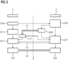
- FIG. 3 shows an example of how the converter 2 and the higher-level control device 3 can interact.
- An arrow labeled "t" indicates the chronological order.
- the converter 2 provides the higher-level control device 3 with relevant data for calculating the second thermal model M2.
- data which are relevant for calculating the second thermal model M2, can be current, voltages, modulation levels, pulse frequencies, etc., for example.
- the relevant data can deviate between those that are stored in the converter and those that are required for the calculation in the higher-level control device. For this reason, the calculation using the first thermal model M1 and the second thermal model M2 can happen differently. For example, within the scope of the first thermal model M1, it is possible to calculate with modulation indices, while within the scope of the second thermal model M2, it is possible to calculate with modulation indices. Because of this, different data can be transmitted.
- a first power loss can be calculated using the converter 2, ie using the first thermal model M1.
- a second (more complex) power loss can preferably be calculated parallel to this in a step S20 by means of the higher-level control device 3, ie by means of the second thermal model M2.
- the second power loss within the framework of the second thermal model M2, one or more of the additional options mentioned above can be selected. For example, the current second temperature T2 and/or non-linear mappings of the conduction characteristics and/or switching energy losses can be taken into account.
- the temperature of the temperature sensor 111 or, in the case of a plurality of temperature sensors, the temperature of each temperature sensor is calculated - step S201.
- the calculated temperature of the temperature sensor is also called "virtual sensor temperature". These calculated virtual sensor temperatures can in turn be compared with the actually measured temperatures of the temperature sensors 111 - step V1. Excessive deviations between the values can indicate a defect in the temperature sensors. An alarm could then be issued that the temperature sensor 111 is defective. Subsequently, the calculation using the first thermal model M1 in the converter 2 (and also the second thermal model M2 in the higher-level control device 3) can be continued with the virtual sensor temperature.
- the first temperature T1 of the IGBT chip 108 in the converter 2 can be calculated.
- the actually measured temperature of the temperature sensor 111 or also the virtual sensor temperature can be used for this.
- the second temperature T2 of the IGBT chip 108 can be calculated in the higher-level control device 3, preferably in parallel with step S12.
- step S12 The second temperature T2 as part of the second thermal model M2
- one or more of the aforementioned additional options can be selected. For example, thermal couplings between different IGBT chips and/or between the IGBT chips and diodes (and/or other electronic components not shown here, which the IGBT module 100 can include) can be taken into account and/or different thermal paths for different ones IGBT and/or diodes (and/or other electronic components not shown here, which the IGBT module 100 may include) etc.
- the first temperature T1 of the IGBT 108 can be compared with the second temperature T2.
- a first wear of the IGBT 108 can be calculated on the basis of the calculated first temperature T1 in the converter 2.
- a second wear of the IGBT 108 based on the calculated second temperature T2 can preferably be calculated parallel to this in a step S22 on the higher-level control device 3 .
- the first wear can be compared with the second wear.
- the accuracy with which the wear of the IGBT 108 is determined can be increased by calculating the wear based on the second temperature T2 determined using the second thermal model M2.
- a more accurate statement can thus be made about the state of the IGBT module 100, as a result of which a better maintenance service can be offered to customers.
- an increase in robustness can be achieved for the customer.
- the converter 2 it is conceivable for the converter 2 to receive all the data (temperatures and wear values) relevant to the operation of the converter 2 from the higher-level control device 3, which can be located in a cloud, for example, as long as there is a data connection between the converter 2 and the higher-level control device 3. In this case, the first thermal model M1 does not have to be calculated at all. As a result, the resources of the converter 2 can be saved.
- the converter 2 can take over the calculation of the first temperature T1 again with its own values.
- the higher-level controller 3 takes over the calculation of the second temperature T2 as long as the converter 2 is switched off. It is thus also possible to determine the temperature when the converter 2 has no supply voltage and can therefore no longer determine the first temperature T1. This is advantageous because when the converter 2 is switched off, the information about the temperature of the IGBT 108 and above all the information about the thermal path is lost. The aforementioned information would no longer be available for calculating the temperature of the IGBT 108 when the converter 2 was switched on again if the temperature was not calculated using the second thermal model M2 on the higher-level control device 3 while the converter 2 was off. This means that when the converter 2 is switched off (no supply voltage), the higher-level control device 3 can continue calculating the temperatures and communicate these temperatures to the converter 2 when it is switched on again.
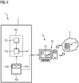
- FIG 4 shows an example of an arrangement 1, which is connected to a cloud 4.
- the first temperature T1 of the electronic components 108, 109 is calculated in the software of the converter 2 using the first thermal model M1, with the first thermal model M1 being able to include two aforementioned sub-steps TS1 and TS2.
- the higher-level control device 3 can have multiple components include.
- higher-level control device 3 includes a local computing unit 30 (not located in the cloud) that is set up to communicate with a cloud server 31 .
- a computer program 32 is stored in an executable manner on the computing unit 30, for example on its hard drive, which is not shown here. When the computer program 32 is executed, it causes the arrangement 1 to carry out one or more of the aforementioned method steps.
- the computer program 32 can cause the computing unit 30 to calculate the second thermal model M2 and, if necessary, to access the computing resources of the cloud server 31, for example to calculate the second temperature T2 according to one or more of the aforementioned options of the second thermal model to determine M2.
- the consideration of all thermal couplings can be computationally intensive, so that in this case the computing resources of the cloud server 31 are quite useful.
Landscapes
- Engineering & Computer Science (AREA)
- Power Engineering (AREA)
- Physics & Mathematics (AREA)
- General Physics & Mathematics (AREA)
- Power Conversion In General (AREA)
Priority Applications (6)
| Application Number | Priority Date | Filing Date | Title |
|---|---|---|---|
| EP20199593.3A EP3979480A1 (fr) | 2020-10-01 | 2020-10-01 | Agencement et procédé de détermination des températures des composants électroniques |
| US18/029,836 US12216009B2 (en) | 2020-10-01 | 2021-09-17 | Arrangement and method for determining temperatures of electronic components |
| PCT/EP2021/075578 WO2022069252A1 (fr) | 2020-10-01 | 2021-09-17 | Agencement et procédé de détermination de températures de composants électroniques |
| CN202180067803.7A CN116325459A (zh) | 2020-10-01 | 2021-09-17 | 用于求出电子器件的温度的装置和方法 |
| EP21778091.5A EP4193456B1 (fr) | 2020-10-01 | 2021-09-17 | Agencement et procédé de détermination des températures des composants électroniques |
| KR1020237014651A KR20230078774A (ko) | 2020-10-01 | 2021-09-17 | 전자 소자들의 온도들을 결정하기 위한 배열체 및 방법 |
Applications Claiming Priority (1)
| Application Number | Priority Date | Filing Date | Title |
|---|---|---|---|
| EP20199593.3A EP3979480A1 (fr) | 2020-10-01 | 2020-10-01 | Agencement et procédé de détermination des températures des composants électroniques |
Publications (1)
| Publication Number | Publication Date |
|---|---|
| EP3979480A1 true EP3979480A1 (fr) | 2022-04-06 |
Family
ID=72717752
Family Applications (2)
| Application Number | Title | Priority Date | Filing Date |
|---|---|---|---|
| EP20199593.3A Withdrawn EP3979480A1 (fr) | 2020-10-01 | 2020-10-01 | Agencement et procédé de détermination des températures des composants électroniques |
| EP21778091.5A Active EP4193456B1 (fr) | 2020-10-01 | 2021-09-17 | Agencement et procédé de détermination des températures des composants électroniques |
Family Applications After (1)
| Application Number | Title | Priority Date | Filing Date |
|---|---|---|---|
| EP21778091.5A Active EP4193456B1 (fr) | 2020-10-01 | 2021-09-17 | Agencement et procédé de détermination des températures des composants électroniques |
Country Status (5)
| Country | Link |
|---|---|
| US (1) | US12216009B2 (fr) |
| EP (2) | EP3979480A1 (fr) |
| KR (1) | KR20230078774A (fr) |
| CN (1) | CN116325459A (fr) |
| WO (1) | WO2022069252A1 (fr) |
Cited By (1)
| Publication number | Priority date | Publication date | Assignee | Title |
|---|---|---|---|---|
| WO2024046613A1 (fr) * | 2022-08-29 | 2024-03-07 | Robert Bosch Gmbh | Dispositif et procédé de détermination d'une température de liquide de refroidissement d'un circuit de refroidissement |
Citations (3)
| Publication number | Priority date | Publication date | Assignee | Title |
|---|---|---|---|---|
| DE10203577A1 (de) * | 2002-01-30 | 2003-08-21 | Siemens Ag | Verfahren zum Prognostizieren der Lebensdauer von leistungselektronischen Bauelementen |
| JP2007028741A (ja) * | 2005-07-14 | 2007-02-01 | Hitachi Ltd | 電力変換器とその管理システム |
| DE102011087764A1 (de) * | 2011-12-05 | 2013-06-06 | Converteam Gmbh | Verfahren und System zum Ermitteln des Lebensdauerverbrauchs von mindestens einem Leistungshalbleiterbauelement eines elektrischen Stromrichters |
Family Cites Families (8)
| Publication number | Priority date | Publication date | Assignee | Title |
|---|---|---|---|---|
| ATE449992T1 (de) * | 2007-03-22 | 2009-12-15 | Baumueller Nuernberg Gmbh | Temperaturüberwachung bei leistungsschaltern |
| US8671294B2 (en) * | 2008-03-07 | 2014-03-11 | Raritan Americas, Inc. | Environmentally cognizant power management |
| JP5443946B2 (ja) * | 2009-11-02 | 2014-03-19 | 株式会社東芝 | インバータ装置 |
| DE102013221587A1 (de) * | 2013-10-24 | 2015-04-30 | Siemens Aktiengesellschaft | Verfahren und Vorrichtung zur Bestimmung einer voraussichtlichen Restlebensdauer eines Bauteils |
| JP5920492B2 (ja) * | 2015-01-20 | 2016-05-18 | ダイキン工業株式会社 | 温度推定装置および半導体装置 |
| US10288672B2 (en) * | 2016-04-08 | 2019-05-14 | Nutech Ventures | Monitoring aging of power semiconductor devices based on case temperature |
| KR20180057141A (ko) * | 2016-11-22 | 2018-05-30 | 현대자동차주식회사 | 계자권선형 모터 제어 시스템 및 방법 |
| KR102445886B1 (ko) * | 2017-12-20 | 2022-09-22 | 현대자동차주식회사 | 온도센서 고장 판단방법 및 판단시스템 |
-
2020
- 2020-10-01 EP EP20199593.3A patent/EP3979480A1/fr not_active Withdrawn
-
2021
- 2021-09-17 EP EP21778091.5A patent/EP4193456B1/fr active Active
- 2021-09-17 WO PCT/EP2021/075578 patent/WO2022069252A1/fr not_active Ceased
- 2021-09-17 CN CN202180067803.7A patent/CN116325459A/zh active Pending
- 2021-09-17 KR KR1020237014651A patent/KR20230078774A/ko active Pending
- 2021-09-17 US US18/029,836 patent/US12216009B2/en active Active
Patent Citations (3)
| Publication number | Priority date | Publication date | Assignee | Title |
|---|---|---|---|---|
| DE10203577A1 (de) * | 2002-01-30 | 2003-08-21 | Siemens Ag | Verfahren zum Prognostizieren der Lebensdauer von leistungselektronischen Bauelementen |
| JP2007028741A (ja) * | 2005-07-14 | 2007-02-01 | Hitachi Ltd | 電力変換器とその管理システム |
| DE102011087764A1 (de) * | 2011-12-05 | 2013-06-06 | Converteam Gmbh | Verfahren und System zum Ermitteln des Lebensdauerverbrauchs von mindestens einem Leistungshalbleiterbauelement eines elektrischen Stromrichters |
Cited By (1)
| Publication number | Priority date | Publication date | Assignee | Title |
|---|---|---|---|---|
| WO2024046613A1 (fr) * | 2022-08-29 | 2024-03-07 | Robert Bosch Gmbh | Dispositif et procédé de détermination d'une température de liquide de refroidissement d'un circuit de refroidissement |
Also Published As
| Publication number | Publication date |
|---|---|
| KR20230078774A (ko) | 2023-06-02 |
| WO2022069252A1 (fr) | 2022-04-07 |
| EP4193456A1 (fr) | 2023-06-14 |
| EP4193456B1 (fr) | 2024-07-24 |
| US12216009B2 (en) | 2025-02-04 |
| EP4193456C0 (fr) | 2024-07-24 |
| CN116325459A (zh) | 2023-06-23 |
| US20230299662A1 (en) | 2023-09-21 |
Similar Documents
| Publication | Publication Date | Title |
|---|---|---|
| EP3224631B1 (fr) | Procédé de détermination d'un vieillissement de modules semi-conducteurs de puissance, dispositif et circuit | |
| EP1973025B1 (fr) | Supervision de la température à proximité des interrupteurs de courant | |
| EP3199929B1 (fr) | Methode et dispositif de mesure de température d'un condensateur à circuit intermédiaire | |
| DE102011121832A1 (de) | Invertervorrichtung | |
| DE102012219646A1 (de) | Halbleitervorrichtung, die eine an ein Halbleiterschaltelement angelegte Spannung misst | |
| DE102020125642B4 (de) | System, Verfahren und Computerprogrammprodukt zur Überwachung der Kühlleistung für einen Halbleiter-Pulswechselrichter | |
| DE102015219867A1 (de) | Platine, B-Lagerschild, Motorbausatz und Elektromotor | |
| DE102017213712B4 (de) | Steuervorrichtung für eine drehende elektrische Maschine, und elektrische Servolenkung, bei der diese verwendet wird | |
| DE112013001012T5 (de) | Multiplexerschaltung für einen Dualthermistorbetrieb unter Verwendung einer Einzelleitungskopplung | |
| WO2013075733A1 (fr) | Circuit de commande électronique comportant des transistors de puissance et procédé de contrôle de la durée de vie des transistors de puissance | |
| DE102009002423A1 (de) | Systeme und Verfahren zum Schätzen von Temperaturen von Komponenten von Leistungsmodulen | |
| DE102012222481A1 (de) | Verfahren zum Ermitteln einer Sperrschichttemperatur eines Leistungshalbleiters unter Berücksichtigung der Degradation und Mittel zu dessen Implementierung | |
| DE102014109515B4 (de) | An ein Wärmeabstrahlelement anzubringende Halbleitervorrichtung | |
| DE10351843A1 (de) | Verfahren und elektrische Schaltungen zur Ermittlung einer Temperatur eines Leistungshalbleiters | |
| DE10048704B4 (de) | Verfahren für eine Vorrichtung mit Leistungshalbleitern und Vorrichtung | |
| DE102018212472B4 (de) | Leistungsumwandlungssystem | |
| DE102021212287B3 (de) | Verfahren und Vorrichtung zum Bestimmen einer Verlustleistung von Halbleiterbauelementen eines Umrichters | |
| DE102013219789A1 (de) | Vorrichtung und Verfahren zur Bestimmung einer Flussgeschwindigkeit eines Kühlmittels durch einen Kühlkanal | |
| DE112019001566T5 (de) | Kühleinrichtung, mit deckel versehene kühleinrichtung, gehäuse mit kühleinrichtung sowie wechselrichter | |
| EP4193456B1 (fr) | Agencement et procédé de détermination des températures des composants électroniques | |
| DE102014219237A1 (de) | Verfahren und Vorrichtung zum Bestimmen von Betriebsparametern von Schaltelementen eines Umrichters | |
| DE102022103471A1 (de) | Elektrische Schaltungseinrichtung, elektrische Antriebseinrichtung und Kraftfahrzeug | |
| DE102014205956A1 (de) | Treiberbaugruppe | |
| WO2024183977A1 (fr) | Convertisseur à refroidissement amélioré, armoire de convertisseur et produit de programme informatique | |
| DE102005021918B4 (de) | Verfahren zur Bestimmung der Temperatur eines Bauelementes |
Legal Events
| Date | Code | Title | Description |
|---|---|---|---|
| PUAI | Public reference made under article 153(3) epc to a published international application that has entered the european phase |
Free format text: ORIGINAL CODE: 0009012 |
|
| STAA | Information on the status of an ep patent application or granted ep patent |
Free format text: STATUS: THE APPLICATION HAS BEEN PUBLISHED |
|
| AK | Designated contracting states |
Kind code of ref document: A1 Designated state(s): AL AT BE BG CH CY CZ DE DK EE ES FI FR GB GR HR HU IE IS IT LI LT LU LV MC MK MT NL NO PL PT RO RS SE SI SK SM TR |
|
| STAA | Information on the status of an ep patent application or granted ep patent |
Free format text: STATUS: THE APPLICATION IS DEEMED TO BE WITHDRAWN |
|
| 18D | Application deemed to be withdrawn |
Effective date: 20221007 |