EP3979210A1 - Systèmes et procédés de déformation non rigide de tissus pour la navigation virtuelle d'outils d'intervention - Google Patents
Systèmes et procédés de déformation non rigide de tissus pour la navigation virtuelle d'outils d'intervention Download PDFInfo
- Publication number
- EP3979210A1 EP3979210A1 EP21211424.3A EP21211424A EP3979210A1 EP 3979210 A1 EP3979210 A1 EP 3979210A1 EP 21211424 A EP21211424 A EP 21211424A EP 3979210 A1 EP3979210 A1 EP 3979210A1
- Authority
- EP
- European Patent Office
- Prior art keywords
- deformed
- processing system
- geometric model
- model
- gpu
- Prior art date
- Legal status (The legal status is an assumption and is not a legal conclusion. Google has not performed a legal analysis and makes no representation as to the accuracy of the status listed.)
- Pending
Links
Images


Classifications
-
- A—HUMAN NECESSITIES
- A61—MEDICAL OR VETERINARY SCIENCE; HYGIENE
- A61B—DIAGNOSIS; SURGERY; IDENTIFICATION
- A61B34/00—Computer-aided surgery; Manipulators or robots specially adapted for use in surgery
- A61B34/10—Computer-aided planning, simulation or modelling of surgical operations
-
- A—HUMAN NECESSITIES
- A61—MEDICAL OR VETERINARY SCIENCE; HYGIENE
- A61B—DIAGNOSIS; SURGERY; IDENTIFICATION
- A61B34/00—Computer-aided surgery; Manipulators or robots specially adapted for use in surgery
- A61B34/20—Surgical navigation systems; Devices for tracking or guiding surgical instruments, e.g. for frameless stereotaxis
-
- A—HUMAN NECESSITIES
- A61—MEDICAL OR VETERINARY SCIENCE; HYGIENE
- A61B—DIAGNOSIS; SURGERY; IDENTIFICATION
- A61B34/00—Computer-aided surgery; Manipulators or robots specially adapted for use in surgery
- A61B34/30—Surgical robots
-
- G—PHYSICS
- G06—COMPUTING; CALCULATING OR COUNTING
- G06T—IMAGE DATA PROCESSING OR GENERATION, IN GENERAL
- G06T19/00—Manipulating 3D models or images for computer graphics
- G06T19/20—Editing of 3D images, e.g. changing shapes or colours, aligning objects or positioning parts
-
- A—HUMAN NECESSITIES
- A61—MEDICAL OR VETERINARY SCIENCE; HYGIENE
- A61B—DIAGNOSIS; SURGERY; IDENTIFICATION
- A61B34/00—Computer-aided surgery; Manipulators or robots specially adapted for use in surgery
- A61B34/10—Computer-aided planning, simulation or modelling of surgical operations
- A61B2034/101—Computer-aided simulation of surgical operations
- A61B2034/105—Modelling of the patient, e.g. for ligaments or bones
-
- A—HUMAN NECESSITIES
- A61—MEDICAL OR VETERINARY SCIENCE; HYGIENE
- A61B—DIAGNOSIS; SURGERY; IDENTIFICATION
- A61B34/00—Computer-aided surgery; Manipulators or robots specially adapted for use in surgery
- A61B34/10—Computer-aided planning, simulation or modelling of surgical operations
- A61B2034/107—Visualisation of planned trajectories or target regions
-
- A—HUMAN NECESSITIES
- A61—MEDICAL OR VETERINARY SCIENCE; HYGIENE
- A61B—DIAGNOSIS; SURGERY; IDENTIFICATION
- A61B34/00—Computer-aided surgery; Manipulators or robots specially adapted for use in surgery
- A61B34/20—Surgical navigation systems; Devices for tracking or guiding surgical instruments, e.g. for frameless stereotaxis
- A61B2034/2046—Tracking techniques
- A61B2034/2051—Electromagnetic tracking systems
-
- A—HUMAN NECESSITIES
- A61—MEDICAL OR VETERINARY SCIENCE; HYGIENE
- A61B—DIAGNOSIS; SURGERY; IDENTIFICATION
- A61B34/00—Computer-aided surgery; Manipulators or robots specially adapted for use in surgery
- A61B34/20—Surgical navigation systems; Devices for tracking or guiding surgical instruments, e.g. for frameless stereotaxis
- A61B2034/2046—Tracking techniques
- A61B2034/2061—Tracking techniques using shape-sensors, e.g. fiber shape sensors with Bragg gratings
-
- A—HUMAN NECESSITIES
- A61—MEDICAL OR VETERINARY SCIENCE; HYGIENE
- A61B—DIAGNOSIS; SURGERY; IDENTIFICATION
- A61B34/00—Computer-aided surgery; Manipulators or robots specially adapted for use in surgery
- A61B34/30—Surgical robots
- A61B2034/301—Surgical robots for introducing or steering flexible instruments inserted into the body, e.g. catheters or endoscopes
-
- G—PHYSICS
- G06—COMPUTING; CALCULATING OR COUNTING
- G06T—IMAGE DATA PROCESSING OR GENERATION, IN GENERAL
- G06T2210/00—Indexing scheme for image generation or computer graphics
- G06T2210/41—Medical
-
- G—PHYSICS
- G06—COMPUTING; CALCULATING OR COUNTING
- G06T—IMAGE DATA PROCESSING OR GENERATION, IN GENERAL
- G06T2219/00—Indexing scheme for manipulating 3D models or images for computer graphics
- G06T2219/20—Indexing scheme for editing of 3D models
- G06T2219/2021—Shape modification
Definitions
- the present disclosure is directed to systems and methods for navigating a patient anatomy to conduct a minimally invasive procedure, and more particularly to systems and methods for dynamically deforming an anatomical passageway model for display.
- Minimally invasive medical techniques are intended to reduce the amount of tissue that is damaged during interventional procedures, thereby reducing patient recovery time, discomfort, and deleterious side effects.
- Such minimally invasive techniques may be performed through natural orifices in a patient anatomy or through one or more surgical incisions.
- clinicians may insert interventional instruments (including surgical, diagnostic, therapeutic, or biopsy instruments) to reach a target tissue location.
- interventional instruments including surgical, diagnostic, therapeutic, or biopsy instruments
- a minimally invasive interventional instrument may navigate natural or surgically created passageways in anatomical systems such as the lungs, the colon, the intestines, the kidneys, the heart, the circulatory system, or the like.
- Teleoperated interventional systems may be used to insert and position the interventional instrument within the patient anatomy.
- the anatomical passageways may deform due to, for example, anatomical motion (e.g. cardiac motion, respiration motion) or a force applied by the interventional instrument.
- anatomical motion e.g. cardiac motion, respiration motion
- Systems and methods are needed to dynamically deform anatomical passageway models for display to a user while navigating the actual patient anatomical passageways with the interventional instrument.
- method of modeling anatomic deformation comprises receiving a reference three dimensional model of a branched anatomical formation in a reference state.
- the method further comprises applying a three dimensional deformation field to the reference three dimensional model to create a deformed three dimensional model of a deformed state of the branched anatomical formation and dynamically displaying an image of the deformed three dimensional model of the deformed state of the branched anatomical formation.
- a processing system comprises a processor and a memory having computer readable instructions stored thereon.
- the computer readable instructions when executed by the processor, cause the system to receive a reference three dimensional model of a branched anatomical formation in a reference state.
- the instructions when executed by the processor also cause the system to apply a three dimensional deformation field to the reference three dimensional model to create a deformed three dimensional model of a deformed state of the branched anatomical formation.
- the instructions when executed by the processor also cause the system to dynamically display an image of the deformed three dimensional model of the deformed state of the branched anatomical formation.
- position refers to the location of an object or a portion of an object in a three-dimensional space (e.g., three degrees of translational freedom along Cartesian X, Y, Z coordinates).
- orientation refers to the rotational placement of an object or a portion of an object (three degrees of rotational freedom - e.g., roll, pitch, and yaw).
- the term “pose” refers to the position of an object or a portion of an object in at least one degree of translational freedom and to the orientation of that object or portion of the object in at least one degree of rotational freedom (up to six total degrees of freedom).
- the term “shape” refers to a set of poses, positions, or orientations measured along an elongated object.
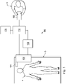
- a telerobotic interventional system for use in, for example, surgical, diagnostic, therapeutic, or biopsy procedures, is generally indicated by the reference numeral 100.
- the telerobotic interventional systems of this disclosure are generally under the teleoperational control of a surgeon.
- the telterobotic interventional system may be under the partial or full control of a computer programmed to perform the procedure or sub-procedure.
- the telerobotic interventional system 100 generally includes a robotic assembly 102 mounted to or near an operating table O on which a patient P is positioned.
- An interventional instrument system 104 is operably coupled to the robotic assembly 102.
- An operator input system 106 allows a surgeon or other type of clinician S to view the surgical site and to control the operation of the interventional instrument system 104.
- the operator input system 106 may be located at a surgeon's console which is usually located in the same room as operating table O. However, it should be understood that the surgeon S can be located in a different room or a completely different building from the patient P.
- Operator input system 106 generally includes one or more control device(s) for controlling the interventional instrument system 104.
- the control device(s) may include any number of a variety of input devices, such as hand grips, joysticks, trackballs, data gloves, trigger-guns, hand-operated controllers, voice recognition devices, touch screens, body motion or presence sensors, or the like.
- control device(s) will be provided with the same degrees of freedom as the interventional instruments of the robotic assembly to provide the surgeon with telepresence, or the perception that the control device(s) are integral with the instruments so that the surgeon has a strong sense of directly controlling instruments.
- the control device(s) may have more or fewer degrees of freedom than the associated interventional instruments and still provide the surgeon with telepresence.
- the control device(s) are manual input devices which move with six degrees of freedom, and which may also include an actuatable handle for actuating instruments (for example, for closing grasping jaws, applying an electrical potential to an electrode, delivering a medicinal treatment, or the like).
- the robotic assembly 102 supports the interventional instrument system 104 and may comprise a kinematic structure of one or more non-servo controlled links (e.g., one or more links that may be manually positioned and locked in place, generally referred to as a set-up structure) and a robotic manipulator.
- the robotic assembly 102 includes plurality of actuators (e.g., motors) that drive inputs on the interventional instrument 104. These motors actively move in response to commands from the control system (e.g., control system 112).
- the motors include drive systems which when coupled to the interventional instrument 104 may advance the interventional instrument into a naturally or surgically created anatomical orifice and/or may move the distal end of the interventional instrument in multiple degrees of freedom, which may include three degrees of linear motion (e.g., linear motion along the X, Y, Z Cartesian axes) and three degrees of rotational motion (e.g., rotation about the X, Y, Z Cartesian axes). Additionally, the motors can be used to actuate an articulable end effector of the instrument for grasping tissue in the jaws of a biopsy device or the like.
- three degrees of linear motion e.g., linear motion along the X, Y, Z Cartesian axes
- rotational motion e.g., rotation about the X, Y, Z Cartesian axes
- the robotic interventional system 100 also includes a sensor system 108 with one or more sub-systems for receiving information about the instruments of the robotic assembly.
- Such sub-systems may include a position sensor system (e.g., an electromagnetic (EM) sensor system); a shape sensor system for determining the position, orientation, speed, pose, and/or shape of the catheter tip and/or of one or more segments along a flexible body of instrument 104; and/or a visualization system for capturing images from the distal end of the catheter system.
- EM electromagnetic
- the robotic interventional system 100 also includes a display system 110 for displaying an image of the surgical site and interventional instruments 104 generated by sub-systems of the sensor system 108.
- the display 110 and the operator input system 106 may be oriented so the operator can control the interventional instrument system 104 and the operator input system 106 as if viewing the workspace in substantially true presence.
- True presence means that the displayed tissue image appears to an operator as if the operator was physically present at the image location and directly viewing the tissue from the perspective of the image.
- display system 110 may present images of the surgical site recorded and/or modeled preoperatively or intra-operatively using imaging technology such as computerized tomography (CT), magnetic resonance imaging (MRI), fluoroscopy, thermography, ultrasound, optical coherence tomography (OCT), thermal imaging, impedance imaging, laser imaging, nanotube X-ray imaging, or the like.
- imaging technology such as computerized tomography (CT), magnetic resonance imaging (MRI), fluoroscopy, thermography, ultrasound, optical coherence tomography (OCT), thermal imaging, impedance imaging, laser imaging, nanotube X-ray imaging, or the like.
- CT computerized tomography
- MRI magnetic resonance imaging
- OCT optical coherence tomography
- thermal imaging impedance imaging
- laser imaging laser imaging
- nanotube X-ray imaging or the like.
- the presented preoperative or intra-operative images may include two-dimensional, three-dimensional, or four-dimensional (including e.g., time based or velocity based information) images and models.
- the display system 110 may display a virtual visualization image in which the actual location of the interventional instrument is registered (e.g., dynamically referenced) with preoperative or concurrent images to present the surgeon with a virtual image of the internal surgical site at the location of the tip of the surgical instrument.
- a virtual visualization image in which the actual location of the interventional instrument is registered (e.g., dynamically referenced) with preoperative or concurrent images to present the surgeon with a virtual image of the internal surgical site at the location of the tip of the surgical instrument.
- the display system 110 may display a virtual visualization image in which the actual location of the interventional instrument is registered with prior images (including preoperatively recorded images) or concurrent images to present the surgeon with a virtual image of an interventional instrument at the surgical site.
- An image of a portion of the interventional instrument 104 may be superimposed on the virtual image to assist the surgeon controlling the interventional instrument.
- the robotic interventional system 100 also includes a control system 112.
- the control system 112 includes at least one memory and at least one processor (not shown), and typically a plurality of processors, for effecting control between the interventional instrument system 104, the operator input system 106, the sensor system 108, and the display system 110.
- the control system 112 also includes programmed instructions (e.g., a computer-readable medium storing the instructions) to implement some or all of the methods described herein. While control system 112 is shown as a single block in the simplified schematic of Fig. 1 , the system may comprise a number of data processing circuits with a portion of the processing optionally being performed on or adjacent the robotic assembly 102, a portion being performed at the operator input system 106, and the like.
- control system 112 supports wireless communication protocols such as Bluetooth, IrDA, HomeRF, IEEE 802.11, DECT, and Wireless Telemetry.
- control system 112 may include one or more servo controllers to provide force and torque feedback from the interventional instrument system 104 to one or more corresponding servomotors for the operator input system 106.
- the servo controller(s) may also transmit signals instructing robotic assembly 102 to move the interventional instruments 104 which extend into an internal surgical site within the patient body via openings in the body. Any suitable conventional or specialized servo controller may be used.
- a servo controller may be separate from, or integrated with, robotic assembly 102.
- the servo controller and robotic assembly are provided as part of a robotic arm cart positioned adjacent to the patient's body.
- the control system 112 may further include a virtual visualization system to provide navigation assistance to the interventional instruments 104.
- Virtual navigation using the virtual visualization system is based upon reference to an acquired dataset associated with the three dimensional structure of the anatomical passageways. More specifically, the virtual visualization system processes images of the surgical site recorded and/or modeled using imaging technology such as computerized tomography (CT), magnetic resonance imaging (MRI), fluoroscopy, thermography, ultrasound, optical coherence tomography (OCT), thermal imaging, impedance imaging, laser imaging, nanotube X-ray imaging, or the like.
- CT computerized tomography
- MRI magnetic resonance imaging
- fluoroscopy thermography
- ultrasound optical coherence tomography
- OCT optical coherence tomography
- thermal imaging impedance imaging
- laser imaging nanotube X-ray imaging, or the like.
- Software is used to convert the recorded images into a two dimensional or three dimensional model of a partial or an entire anatomical organ or anatomical region.
- the model describes the various locations
- the images used to generate the model may be recorded preoperatively or intra-operatively during a clinical procedure.
- a virtual visualization system may use standard models (i.e., not patient specific) or hybrids of a standard model and patient specific data.
- the model and any virtual images generated by the model may represent the static posture of a deformable anatomic region during one or more phases of motion (e.g., during an inspiration/ expiration cycle of a lung).
- the sensor system 108 may be used to compute an approximate location of the instrument with respect to the patient anatomy.
- the location can be used to produce both macro-level tracking images of the patient anatomy and virtual internal images of the patient anatomy.
- Various systems for using fiber optic sensors to register and display an interventional implement together with preoperatively recorded surgical images, such as those from a virtual visualization system are known.
- U.S. Patent Application No. 13/107,562 filed May 13, 2011 , disclosing, "Medical System Providing Dynamic Registration of a Model of an Anatomical Structure for Image-Guided Surgery," which is incorporated by reference herein in its entirety, discloses one such system.
- the robotic interventional system 100 may further include optional operation and support systems (not shown) such as illumination systems, steering control systems, irrigation systems, and/or suction systems.
- the robotic system may include more than one robotic assembly and/or more than one operator input system.
- the exact number of manipulator assemblies will depend on the surgical procedure and the space constraints within the operating room, among other factors.
- the operator input systems may be collocated, or they may be positioned in separate locations. Multiple operator input systems allow more than one operator to control one or more manipulator assemblies in various combinations.
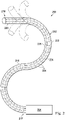
- FIG. 2 illustrates an interventional instrument system 200 which may be used as the interventional instrument system 104 of robotic interventional system 100.
- the interventional instrument system 200 may be used for non-robotic exploratory procedures or in procedures involving traditional manually operated interventional instruments, such as endoscopy.
- the instrument system 200 includes a catheter system 202 coupled to an instrument body 204.
- the catheter system 202 includes an elongated flexible catheter body 216 having a proximal end 217 and a distal end or tip portion 218.
- the flexible body 216 has an approximately 3 mm outer diameter. Other flexible body outer diameters may be larger or smaller.
- the catheter system 202 may optionally include a shape sensor 222 for determining the position, orientation, speed, pose, and/or shape of the catheter tip at distal end 218 and/or of one or more segments 224 along the body 216. The entire length of the body 216, between the distal end 218 and the proximal end 217 may be effectively divided into the segments 224.
- the shape sensor 222 may be a component of the sensor system 108. If the instrument system 200 is manually operated or otherwise used for non-robotic procedures, the shape sensor 222 may be coupled to a tracking system that interrogates the shape sensor and processes the received shape data.
- the shape sensor system 222 may include an optical fiber aligned with the flexible catheter body 216 (e.g., provided within an interior channel (not shown) or mounted externally).
- the optical fiber has a diameter of approximately 200 ⁇ m. In other embodiments, the dimensions may be larger or smaller.
- the optical fiber of the shape sensor system 222 forms a fiber optic bend sensor for determining the shape of the catheter system 202.
- optical fibers including Fiber Bragg Gratings (FBGs) are used to provide strain measurements in structures in one or more dimensions.
- FBGs Fiber Bragg Gratings
- Various systems and methods for monitoring the shape and relative position of an optical fiber in three dimensions are described in U.S. Pat. App. No. 11/180,389, filed July, 13, 2005 , disclosing "Fiber optic position and shape sensing device and method relating thereto;" U.S. Provisional Pat. App. No. 60/588,336, filed on Jul. 16, 2004 , disclosing "Fiber-optic shape and relative position sensing;" and U.S. Pat. No. 6,389,187, filed on Jun.
- the shape of the catheter may be determined using other techniques. For example, if the history of the catheter's distal tip pose is stored for an interval of time that is smaller than the period for refreshing the navigation display or for alternating motion (e.g., inhalation and exhalation), the pose history can be used to reconstruct the shape of the device over the interval of time.
- historical pose, position, or orientation data may be stored for a known point of an instrument along a cycle of alternating motion, such as breathing. This stored data may be used to develop shape information about the catheter.
- a series of positional sensors, such as EM sensors, positioned along the catheter can be used for shape sensing.
- a history of data from a positional sensor, such as an EM sensor, on the instrument during a procedure may be used to represent the shape of the instrument, particularly if an anatomical passageway is generally static.
- a wireless device with position or orientation controlled by an external magnetic field may be used for shape sensing. The history of its position may be used to determine a shape for the navigated passageways.
- the optical fiber may include multiple cores within a single cladding.
- Each core may be single-mode with sufficient distance and cladding separating the cores such that the light in each core does not interact significantly with the light carried in other cores.
- the number of cores may vary or each core may be contained in a separate optical fiber.
- an array of FBG's is provided within each core.
- Each FBG comprises a series of modulations of the core's refractive index so as to generate a spatial periodicity in the refraction index.
- the spacing may be chosen so that the partial reflections from each index change add coherently for a narrow band of wavelengths, and therefore reflect only this narrow band of wavelengths while passing through a much broader band.
- the modulations are spaced by a known distance, thereby causing reflection of a known band of wavelengths.
- the spacing of the modulations will change, depending on the amount of strain in the core.
- backscatter or other optical phenomena that vary with bending of the optical fiber can be used to determine strain within each core.
- FBG FBG's produce a reflected wavelength that is a function of the strain on the fiber and its temperature.
- This FBG technology is commercially available from a variety of sources, such as Smart Fibres Ltd. of Bracknell, England.
- Use of FBG technology in position sensors for robotic surgery is described in U.S. Pat. No. 7,930,065, filed July 20, 2006 , disclosing "Robotic Surgery System Including Position Sensors Using Fiber Bragg Gratings," which is incorporated by reference herein in its entirety.
- bending of the optical fiber When applied to a multicore fiber, bending of the optical fiber induces strain on the cores that can be measured by monitoring the wavelength shifts in each core.
- bending of the fiber induces different strains on each of the cores. These strains are a function of the local degree of bending of the fiber. For example, regions of the cores containing FBG's, if located at points where the fiber is bent, can thereby be used to determine the amount of bending at those points.
- These data combined with the known spacings of the FBG regions, can be used to reconstruct the shape of the fiber.
- Such a system has been described by Luna Innovations. Inc. of Blacksburg, Va.
- the optical fiber may be used to monitor the shape of at least a portion of the catheter system 202. More specifically, light passing through the optical fiber is processed to detect the shape of the catheter system 202 and for utilizing that information to assist in surgical procedures.
- the sensor system e.g. sensor system 108
- the sensor system may include an interrogation system for generating and detecting the light used for determining the shape of the catheter system 202. This information, in turn, can be used to determine other related variables, such as velocity and acceleration of the parts of an interventional instrument.
- the sensing may be limited only to the degrees of freedom that are actuated by the robotic system, or may be applied to both passive (e.g., unactuated bending of the rigid members between joints) and active (e.g., actuated movement of the instrument) degrees of freedom.
- the interventional instrument system may optionally include a position sensor system 220.
- the position sensor system 220 may be an electromagnetic (EM) sensor system that includes one or more conductive coils that may be subjected to an externally generated electromagnetic field. Each coil of the EM sensor system 220 then produces an induced electrical signal having characteristics that depend on the position and orientation of the coil relative to the externally generated electromagnetic field.
- EM electromagnetic
- the EM sensor system may be configured and positioned to measure six degrees of freedom, e.g., three position coordinates X, Y, Z and three orientation angles indicating pitch, yaw, and roll of a base point or five degrees of freedom, e.g., three position coordinates X, Y, Z and two orientation angles indicating pitch and yaw of a base point.
- six degrees of freedom e.g., three position coordinates X, Y, Z and three orientation angles indicating pitch, yaw, and roll of a base point
- five degrees of freedom e.g., three position coordinates X, Y, Z and two orientation angles indicating pitch and yaw of a base point.
- the flexible catheter body 216 includes a channel sized and shaped to receive an auxiliary tool 226.
- Auxiliary tools may include, for example, image capture probes, biopsy devices, laser ablation fibers, or other surgical, diagnostic, or therapeutic tools.
- Auxiliary tools may include end effectors having a single working member such as a scalpel, a blade, an optical fiber, or an electrode.
- Other end effectors may include a pair or plurality of working members such as forceps, graspers, scissors, or clip appliers, for example. Examples of electrically activated end effectors include electrosurgical electrodes, transducers, sensors, and the like.
- the auxiliary tool 226 may be an image capture probe including a distal portion with a stereoscopic or monoscopic camera disposed near the distal end 218 of the flexible catheter body 216 for capturing images (including video images) that are processed for display.
- the image capture probe may include a cable coupled to the camera for transmitting the captured image data.
- the image capture instrument may be a fiber-optic bundle, such as a fiberscope, that couples to the imaging system.
- the image capture instrument may be single or multi-spectral, for example capturing image data in the visible spectrum, or capturing image data in the visible and infrared or ultraviolet spectrums.
- the flexible catheter body 216 may also house cables, linkages, or other steering controls (not shown) that extend between the instrument body 204 and the distal end 218 to controllably bend or turn the distal end 218 as shown for example by the dotted line versions of the distal end.
- the instrument body 204 may include drive inputs that couple to motorized drive elements of the robotic assembly.
- the instrument body 204 may include gripping features, manual actuators, and other components for manually controlling the motion of the instrument system.
- the catheter system may be steerable or, alternatively, may be non-steerable with no integrated mechanism for operator control of the instrument bending.
- the flexible body 216 can define one or more lumens through which interventional instruments can be deployed and used at a target surgical location.
- the interventional instrument system 200 may include a flexible bronchial instrument, such as a bronchoscope or bronchial catheter for use in examination, diagnosis, biopsy, or treatment of a lung.
- a flexible bronchial instrument such as a bronchoscope or bronchial catheter for use in examination, diagnosis, biopsy, or treatment of a lung.
- the system is also suited for navigation and treatment of other tissues, via natural or surgically created connected passageways, in any of a variety of anatomical systems including the colon, the intestines, the kidneys, the brain, the heart, the circulatory system, or the like.
- an interventional instrument system 200 When using an interventional instrument system 200 to conduct a procedure within a patient it may be desirable for the surgeon to have simultaneous access to various forms of data related to the procedure, as described herein. For instance, when guiding an interventional instrument through certain portions of the anatomy such as the respiratory system, an endoscope may be too large to fit safely through the anatomy alongside the interventional instrument system 200. In such procedures, the surgeon may wish to supplement or replace the display of an endoscopic camera with the display of preoperative or intraoperative images of the type described above. Additionally, the surgeon may wish to supplement the display of an endoscopic camera with the display of an overview representation of the anatomy indicating the location of the interventional instrument relative to the procedure site or a particular target location within the anatomy.
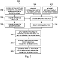
- FIG. 3 illustrates a method 300 for generating a dynamic display of a three dimensional volumetric representation of anatomic passageways in a deformed state.
- a three dimensional volumetric representation i.e., a solid model
- CT computerized tomography
- MRI magnetic resonance imaging
- OCT optical coherence tomography
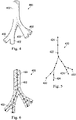
- FIG. 4 illustrates at least a portion of a three dimensional volumetric representation 400 of patient anatomic passageways as received or created at step 302 of the method 300.
- the three dimensional volumetric representation 400 represents the various lung passageways 402 in a reference state, such as a full exhalation state of a patient's breathing cycle.
- the method 300 further includes, at 304, creating a piecewise rigid reference skeleton tree of nodes and linkages from the reference model in the reference state.
- FIG. 5 illustrates a skeleton tree 420 based on the three dimensional volumetric representation 400 and includes a plurality of nodes 422 interconnected by linkages 424 to approximate the structure of the three dimensional volumetric representation 400.
- the nodes 402 of the skeleton tree 420 may be located at bifurcations of the anatomic passageways, at points of significant bend or twist, and/or at any other point along the anatomic passageway.
- the nodes may be generally centered within the anatomic passageways, but in alternative embodiments may be located along passageway walls or at other locations with respect to reference structures of the anatomy.
- the linkages 424 are straight segments that extend between the nodes. The linkages are generally centered within the anatomic passageways, but in alternative embodiments may be located along passageway walls or at other locations with respect to reference structures of the anatomy.
- the method 300 further includes, at 306, creating a reference geometric model.
- the geometric model 450 is a polygon mesh model comprised of a plurality of triangles 452 representing the a surface (interior or exterior) of the anatomic passageways.
- a mesh model for a portion of an anatomic passageway may include approximately 130,000 triangles.
- the polygon mesh model may comprise quadrilaterals or other flat, convex, or concave polygons.
- Each vertex of mesh model 450 may be bound to one of the nodes 422 the skeleton tree 420.
- each vertex of the mesh model 450 bound to a selected node 422 is also bound to the skeleton linkages 424 connected to that selected node.
- the method 300 further includes, at 308, measuring at least one deformation of the anatomic passageways due to anatomical motion.
- Many regions of the patient anatomy are dynamic in normal function (e.g., heart, lungs, kidneys, liver, blood vessels).
- the anatomical motion may be cyclical anatomical motion of the lungs caused by, for example, respiration or the cardiac cycle.
- the deformation is measured in at least one state of the anatomic cycle different from the state of the reference state. For example, if the reference state for the respiration cycle is full exhalation, the deformed state may be at a state of full inhalation. Additionally or alternatively, the deformed state may occur at a state between full inhalation and full exhalation.
- the reference state may be, for example, the early diastole state and the deformed state may be another phase of the cardiac cycle such as atrial systole, isovolumic ventricular contraction, ventricular ejection, or isovolumic ventricular relaxation states.
- the deformation of the anatomic passageways may be determined from preoperative or intra-operative images using any of the previously described imaging technologies, from shape sensor measurements, from position sensor measurements, or other known methods of measuring deformation due to motion.
- the method 300 includes measuring deformation of the anatomic passageways due to forces applied by an interventional instrument (e.g., catheter 202) positioned internal to the passageways.
- the shape of the interventional instrument may be sensed using any of the above described methods for instrument shape sensing, including, for example the use of an optical shape sensing fiber.
- the method 300 includes creating a skeleton tree deformed by the influence of the anatomical motion and the interventional instrument.
- FIG. 7 illustrates a skeleton tree 460 of the anatomic passageways in a deformed state due to anatomic motion.
- the lung passageways are in the deformed state of full inspiration.
- the position of the nodes 422 and the position and orientation of the linkages 424 are modified to align with the anatomic passageways from the imaged anatomy in the deformed state.
- FIG. 8 illustrates a skeleton tree 470 of the anatomic passageways in the reference state of expiration but in a deformed state due to forces applied by an interventional instrument 472 within some of the anatomic passageways.
- FIG. 9 illustrates a skeleton tree 480 of the anatomic passageways in a deformed state due to the combination of anatomic motion (e.g., full inspiration FIG. 7 ) and forces applied by the interventional instrument (e.g., FIG. 8 ).
- deformations of the anatomical passageways caused by other forces may be measured and used to create the composite deformed skeleton tree.
- the method 300 further includes, at 314, creating a deformation field to describe the measured deformations due to anatomical motion and/or interventional instrument forces.
- the deformation field may include a three dimensional field vector array describing the deformation of the anatomical passageways from the full exhalation reference state to the full inhalation deformation state with a sequence of intermediate deformation states between the reference state and the full deformation state.
- a deformation field 490 may include a three dimensional field vector array describing the three dimensional deformation of skeleton tree 420 into the skeleton tree 480.
- the method 300 further includes, at 316, applying the deformation field to the reference geometric model to create a deformed geometric model.
- applying the deformation field to the reference geometric model to create a deformed geometric model.
- an interpolation of the deformation field 490 is performed at each time t.
- Each vertex from the reference mesh model 450 is then transformed into a corresponding vertex of a deformed mesh model 500 ( FIG. 11 ).
- LBS Linear blend skinning
- N the number of bone influences
- i a link in the skeleton
- M an absolute link transform matrix, such as the deformation field 490, which describes the skeletal deformation.
- An example method for determining the weightings is provided.
- N two linkage influences (i.e., bone influences) for a selected vertex v of the mesh
- N 2 in the deformation formula.
- the two closest links to v are chosen.
- the first closest link is l 1 and the second closest link is l 2 .
- the distance between v and l 1 ( l 2 ) is d v ,l 1 ( d v ,l 2 ), defined as the shortest Euclidean distance between v and a point of / 1 ( l 2 ) .
- the dot product of vectors is applied to test whether the shortest distance between a point P (at the vertex v) and a segment S (i.e., a linkage of the skeleton) is between P and one of the endpoints of S. This testing is described as follows:
- the algorithm may also be represented as:
- each vertex of the mesh can be determined and each deformed vertex ( v deformed ) in the mesh may be determined.
- An implementation of the mesh model deformation using a graphics processing unit (GPU) is provided at FIG. 14 .
- the method 300 further includes, at 318, deforming the reference three dimensional volumetric representation 400 into alignment with the deformed mesh to generate an image of the deformed three dimensional volumetric representation 510 as shown in FIG. 12 .
- a composite image 520 ( FIG. 13 ) is generated displaying the deformed three dimensional volumetric representation 510 or deformed mesh model 450 with an image of the interventional instrument 472.
- a software and/or hardware based accelerator such as a parallel computing platform that uses GPU, may be used.
- the deformed images of the anatomic passageways, from the reference state to the full deformation state and including all of the intermediate deformation states may be displayed.
- the GPU may allow display of the reference and deformed state images at a rate of approximately 30 different frames per second and in some embodiments at a rate of approximately 50 different frames per second.
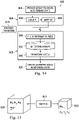
- FIG. 14 illustrates a method 600 of mesh model deformation [e.g., step 316 of method 300] using a GPU 602.
- the mesh model in the reference state e.g., mesh 450
- CPU central processing unit
- a loader 608 running on the CPU 606 loads the mesh model to a main memory (not shown). From the memory, the mesh model is transferred to the GPU 602.
- FIG. 15 illustrates a mapping technique for mapping between the mesh space 630 (e.g., a portion of the mesh model 450) to a 3D texture space 632 that is stored in 3D texture memory 612.
- the 3D texture memory 612 on the GPU 602 stores a rigid transform for each node of the skeleton tree and for interpolated coordinates between the skeleton nodes.
- the 3D texture memory provides a fast and convenient format for storing the rigid transforms for the skeleton nodes and for interpolating transforms for coordinates in between the nodes. The speed of the interpolation allows for the transformation and movement of the mesh model bound to the skeleton model in approximately real time.
- Each (T x , T y , T z ) texture space coordinate in a 3D texture memory space 632 is mapped to a corresponding mesh space coordinate (M x , M y , M z ) in the mesh model space 630.
- closest links l 1 ( l 2 ) and weightings w 1 ( w 2 ) are determined as described above for the LBS technique.
- mapping phase 610 is a mapping table (shown below) with 5 columns if and only if w 1 ⁇ 0. (T x , T y , T z ) Index of l 1 w 1 Index of l 2 w 2
- the mapping table may only need to be computed once for each deformation. The mapping table is moved to the GPU 602.
- a non-rigid transform 614 is moved to the GPU 602.
- the non-rigid transform algorithm 614 is used to compute a rigid transform for each node of the skeleton tree 420 to describe how that node should move based on the deformed skeleton tree 480.
- the non-rigid transform 614 is used by the GPU 602 to compute a transform for each node in the skeleton tree.
- a full deformation field is developed, from the transformed skeleton tree nodes, for each interpolated coordinate in the 3D texture space 632.
- the 3D texture memory 612 stores the transforms for each coordinate in the 3D texture space 632.
- the fields of the 3D texture memory 612 are filled simultaneously by the GPU.
- Separate threads i.e., small sequences of independently managed programmed instructions
- the GPU work to compute a deformation value, using the Deformation Formula provided above, for each coordinate of the 3D texture memory.
- the 3D texture memory in the GPU serves two purposes. First, the dimensions of the texture are much smaller than the model space. For example, the 3D texture memory may use a 128 x 128 x 128 voxel array and the model space may use a 1024 x 1024 x 1024 voxel array. Second, fetching the value in the 3D texture memory of the GPU with linear interpolation is very fast.
- a thread fetches a value (using the mapping table) from the 3D texture memory 612 that corresponds to the position of the vertex in the initial mesh model 450 and transforms it into a deformed vertex.
- a deformed mesh model is generated and displayed.
- the display of the deformed mesh model may be presented dynamically with the display of the deforming mesh model updated at a high display rate corresponding to the near real-time deformation of the patient anatomy. For example, the rate of display may be approximately 30 or more frames per second.
- One or more elements in embodiments of the invention may be implemented in software to execute on a processor of a computer system such as control system 112.
- the elements of the embodiments of the invention are essentially the code segments to perform the necessary tasks.
- the program or code segments can be stored in a processor readable storage medium or device that may have been downloaded by way of a computer data signal embodied in a carrier wave over a transmission medium or a communication link.
- the processor readable storage device may include any medium that can store information including an optical medium, semiconductor medium, and magnetic medium.
- Processor readable storage device examples include an electronic circuit; a semiconductor device, a semiconductor memory device, a read only memory (ROM), a flash memory, an erasable programmable read only memory (EPROM); a floppy diskette, a CD-ROM, an optical disk, a hard disk, or other storage device,
- the code segments may be downloaded via computer networks such as the Internet, intranet, etc.
Applications Claiming Priority (3)
| Application Number | Priority Date | Filing Date | Title |
|---|---|---|---|
| US201461935547P | 2014-02-04 | 2014-02-04 | |
| EP15745879.5A EP3102143A4 (fr) | 2014-02-04 | 2015-02-03 | Systèmes et procédés de déformation non rigide de tissus pour la navigation virtuelle d'outils d'intervention |
| PCT/US2015/014226 WO2015119935A1 (fr) | 2014-02-04 | 2015-02-03 | Systèmes et procédés de déformation non rigide de tissus pour la navigation virtuelle d'outils d'intervention |
Related Parent Applications (1)
| Application Number | Title | Priority Date | Filing Date |
|---|---|---|---|
| EP15745879.5A Division EP3102143A4 (fr) | 2014-02-04 | 2015-02-03 | Systèmes et procédés de déformation non rigide de tissus pour la navigation virtuelle d'outils d'intervention |
Publications (1)
| Publication Number | Publication Date |
|---|---|
| EP3979210A1 true EP3979210A1 (fr) | 2022-04-06 |
Family
ID=53778370
Family Applications (2)
| Application Number | Title | Priority Date | Filing Date |
|---|---|---|---|
| EP21211424.3A Pending EP3979210A1 (fr) | 2014-02-04 | 2015-02-03 | Systèmes et procédés de déformation non rigide de tissus pour la navigation virtuelle d'outils d'intervention |
| EP15745879.5A Ceased EP3102143A4 (fr) | 2014-02-04 | 2015-02-03 | Systèmes et procédés de déformation non rigide de tissus pour la navigation virtuelle d'outils d'intervention |
Family Applications After (1)
| Application Number | Title | Priority Date | Filing Date |
|---|---|---|---|
| EP15745879.5A Ceased EP3102143A4 (fr) | 2014-02-04 | 2015-02-03 | Systèmes et procédés de déformation non rigide de tissus pour la navigation virtuelle d'outils d'intervention |
Country Status (6)
| Country | Link |
|---|---|
| US (6) | US10314656B2 (fr) |
| EP (2) | EP3979210A1 (fr) |
| JP (2) | JP2017511712A (fr) |
| KR (2) | KR20160118295A (fr) |
| CN (1) | CN106170265B (fr) |
| WO (1) | WO2015119935A1 (fr) |
Families Citing this family (103)
| Publication number | Priority date | Publication date | Assignee | Title |
|---|---|---|---|---|
| US8218847B2 (en) | 2008-06-06 | 2012-07-10 | Superdimension, Ltd. | Hybrid registration method |
| US8672837B2 (en) | 2010-06-24 | 2014-03-18 | Hansen Medical, Inc. | Methods and devices for controlling a shapeable medical device |
| US9057600B2 (en) | 2013-03-13 | 2015-06-16 | Hansen Medical, Inc. | Reducing incremental measurement sensor error |
| US9629595B2 (en) | 2013-03-15 | 2017-04-25 | Hansen Medical, Inc. | Systems and methods for localizing, tracking and/or controlling medical instruments |
| US9014851B2 (en) | 2013-03-15 | 2015-04-21 | Hansen Medical, Inc. | Systems and methods for tracking robotically controlled medical instruments |
| US9271663B2 (en) | 2013-03-15 | 2016-03-01 | Hansen Medical, Inc. | Flexible instrument localization from both remote and elongation sensors |
| US11020016B2 (en) | 2013-05-30 | 2021-06-01 | Auris Health, Inc. | System and method for displaying anatomy and devices on a movable display |
| EP3979210A1 (fr) | 2014-02-04 | 2022-04-06 | Intuitive Surgical Operations, Inc. | Systèmes et procédés de déformation non rigide de tissus pour la navigation virtuelle d'outils d'intervention |
| JP6725423B2 (ja) * | 2014-02-11 | 2020-07-15 | コーニンクレッカ フィリップス エヌ ヴェKoninklijke Philips N.V. | 解剖学的標的を視覚化するシステム |
| EP3243476B1 (fr) | 2014-03-24 | 2019-11-06 | Auris Health, Inc. | Systèmes et dispositifs pour le guidage instinctif d'un cathéter |
| US9633431B2 (en) | 2014-07-02 | 2017-04-25 | Covidien Lp | Fluoroscopic pose estimation |
| US9603668B2 (en) | 2014-07-02 | 2017-03-28 | Covidien Lp | Dynamic 3D lung map view for tool navigation inside the lung |
| US10373719B2 (en) | 2014-09-10 | 2019-08-06 | Intuitive Surgical Operations, Inc. | Systems and methods for pre-operative modeling |
| CN107427327A (zh) | 2014-09-30 | 2017-12-01 | 奥瑞斯外科手术机器人公司 | 具有虚拟轨迹和柔性内窥镜的可配置机器人外科手术系统 |
| US10314463B2 (en) | 2014-10-24 | 2019-06-11 | Auris Health, Inc. | Automated endoscope calibration |
| US9974525B2 (en) | 2014-10-31 | 2018-05-22 | Covidien Lp | Computed tomography enhanced fluoroscopic system, device, and method of utilizing the same |
| US10702226B2 (en) | 2015-08-06 | 2020-07-07 | Covidien Lp | System and method for local three dimensional volume reconstruction using a standard fluoroscope |
| US10674982B2 (en) | 2015-08-06 | 2020-06-09 | Covidien Lp | System and method for local three dimensional volume reconstruction using a standard fluoroscope |
| US10716525B2 (en) | 2015-08-06 | 2020-07-21 | Covidien Lp | System and method for navigating to target and performing procedure on target utilizing fluoroscopic-based local three dimensional volume reconstruction |
| JP6824967B2 (ja) | 2015-09-18 | 2021-02-03 | オーリス ヘルス インコーポレイテッド | 管状網のナビゲーション |
| US10271757B2 (en) | 2015-09-26 | 2019-04-30 | Boston Scientific Scimed Inc. | Multiple rhythm template monitoring |
| US10405766B2 (en) | 2015-09-26 | 2019-09-10 | Boston Scientific Scimed, Inc. | Method of exploring or mapping internal cardiac structures |
| EP3353753A1 (fr) * | 2015-09-26 | 2018-08-01 | Boston Scientific Scimed Inc. | Systèmes et procédés pour éditer une enveloppe anatomique |
| US10143526B2 (en) | 2015-11-30 | 2018-12-04 | Auris Health, Inc. | Robot-assisted driving systems and methods |
| WO2017119112A1 (fr) * | 2016-01-08 | 2017-07-13 | オリンパス株式会社 | Système de manipulateur et procédé d'entraînement de celui-ci |
| US9898858B2 (en) * | 2016-05-18 | 2018-02-20 | Siemens Healthcare Gmbh | Human body representation with non-rigid parts in an imaging system |
| US9931025B1 (en) * | 2016-09-30 | 2018-04-03 | Auris Surgical Robotics, Inc. | Automated calibration of endoscopes with pull wires |
| WO2018122946A1 (fr) | 2016-12-27 | 2018-07-05 | オリンパス株式会社 | Procédé d'acquisition de forme et procédé de commande de manipulateur médical |
| US10244926B2 (en) | 2016-12-28 | 2019-04-02 | Auris Health, Inc. | Detecting endolumenal buckling of flexible instruments |
| US11793579B2 (en) | 2017-02-22 | 2023-10-24 | Covidien Lp | Integration of multiple data sources for localization and navigation |
| KR102558061B1 (ko) | 2017-03-31 | 2023-07-25 | 아우리스 헬스, 인코포레이티드 | 생리적 노이즈를 보상하는 관강내 조직망 항행을 위한 로봇 시스템 |
| EP3613057A4 (fr) * | 2017-04-18 | 2021-04-21 | Intuitive Surgical Operations, Inc. | Interface utilisateur graphique pour la planification d'une intervention |
| KR20240035632A (ko) | 2017-05-12 | 2024-03-15 | 아우리스 헬스, 인코포레이티드 | 생검 장치 및 시스템 |
| US10022192B1 (en) | 2017-06-23 | 2018-07-17 | Auris Health, Inc. | Automatically-initialized robotic systems for navigation of luminal networks |
| EP3645100A4 (fr) | 2017-06-28 | 2021-03-17 | Auris Health, Inc. | Compensation d'insertion d'instrument |
| US10699448B2 (en) | 2017-06-29 | 2020-06-30 | Covidien Lp | System and method for identifying, marking and navigating to a target using real time two dimensional fluoroscopic data |
| US10426559B2 (en) | 2017-06-30 | 2019-10-01 | Auris Health, Inc. | Systems and methods for medical instrument compression compensation |
| US10145747B1 (en) | 2017-10-10 | 2018-12-04 | Auris Health, Inc. | Detection of undesirable forces on a surgical robotic arm |
| CN111163697B (zh) | 2017-10-10 | 2023-10-03 | 柯惠有限合伙公司 | 用于在荧光三维重构中识别和标记目标的系统和方法 |
| US11058493B2 (en) | 2017-10-13 | 2021-07-13 | Auris Health, Inc. | Robotic system configured for navigation path tracing |
| US10555778B2 (en) | 2017-10-13 | 2020-02-11 | Auris Health, Inc. | Image-based branch detection and mapping for navigation |
| KR102645922B1 (ko) | 2017-12-06 | 2024-03-13 | 아우리스 헬스, 인코포레이티드 | 지시되지 않은 기구 롤을 수정하기 위한 시스템 및 방법 |
| KR20200100613A (ko) | 2017-12-14 | 2020-08-26 | 아우리스 헬스, 인코포레이티드 | 기구 위치 추정을 위한 시스템 및 방법 |
| KR20200101334A (ko) | 2017-12-18 | 2020-08-27 | 아우리스 헬스, 인코포레이티드 | 관강내 조직망 내 기구 추적 및 항행을 위한 방법 및 시스템 |
| CN111885980B (zh) | 2018-01-17 | 2023-03-28 | 奥瑞斯健康公司 | 具有可调式臂支撑件的外科平台 |
| US10930064B2 (en) | 2018-02-08 | 2021-02-23 | Covidien Lp | Imaging reconstruction system and method |
| US10893842B2 (en) | 2018-02-08 | 2021-01-19 | Covidien Lp | System and method for pose estimation of an imaging device and for determining the location of a medical device with respect to a target |
| US10905498B2 (en) | 2018-02-08 | 2021-02-02 | Covidien Lp | System and method for catheter detection in fluoroscopic images and updating displayed position of catheter |
| WO2019164271A1 (fr) * | 2018-02-20 | 2019-08-29 | (주)휴톰 | Procédé et dispositif de génération de modèle de corps humain virtuel |
| KR102018565B1 (ko) * | 2018-02-20 | 2019-09-05 | (주)휴톰 | 수술 시뮬레이션 정보 구축 방법, 장치 및 프로그램 |
| EP3773131A4 (fr) | 2018-03-28 | 2021-12-15 | Auris Health, Inc. | Systèmes et procédés d'enregistrement de capteurs d'emplacement |
| JP7225259B2 (ja) | 2018-03-28 | 2023-02-20 | オーリス ヘルス インコーポレイテッド | 器具の推定位置を示すためのシステム及び方法 |
| CN110831486B (zh) * | 2018-05-30 | 2022-04-05 | 奥瑞斯健康公司 | 用于基于定位传感器的分支预测的系统和方法 |
| WO2019232236A1 (fr) | 2018-05-31 | 2019-12-05 | Auris Health, Inc. | Analyse et cartographie de voies respiratoires basées sur une image |
| CN112236083A (zh) | 2018-05-31 | 2021-01-15 | 奥瑞斯健康公司 | 用于导航检测生理噪声的管腔网络的机器人系统和方法 |
| KR20210018858A (ko) | 2018-05-31 | 2021-02-18 | 아우리스 헬스, 인코포레이티드 | 관상 네트워크의 경로-기반 내비게이션 |
| US11071591B2 (en) | 2018-07-26 | 2021-07-27 | Covidien Lp | Modeling a collapsed lung using CT data |
| US11705238B2 (en) | 2018-07-26 | 2023-07-18 | Covidien Lp | Systems and methods for providing assistance during surgery |
| AU2019326548B2 (en) | 2018-08-24 | 2023-11-23 | Auris Health, Inc. | Manually and robotically controllable medical instruments |
| MX2021003099A (es) | 2018-09-17 | 2021-05-13 | Auris Health Inc | Sistemas y metodos para procedimientos medicos concomitantes. |
| US11944388B2 (en) | 2018-09-28 | 2024-04-02 | Covidien Lp | Systems and methods for magnetic interference correction |
| AU2019347767A1 (en) | 2018-09-28 | 2021-04-08 | Auris Health, Inc. | Systems and methods for docking medical instruments |
| US11877806B2 (en) | 2018-12-06 | 2024-01-23 | Covidien Lp | Deformable registration of computer-generated airway models to airway trees |
| US11045075B2 (en) | 2018-12-10 | 2021-06-29 | Covidien Lp | System and method for generating a three-dimensional model of a surgical site |
| US11801113B2 (en) | 2018-12-13 | 2023-10-31 | Covidien Lp | Thoracic imaging, distance measuring, and notification system and method |
| US11617493B2 (en) | 2018-12-13 | 2023-04-04 | Covidien Lp | Thoracic imaging, distance measuring, surgical awareness, and notification system and method |
| WO2020131186A1 (fr) | 2018-12-20 | 2020-06-25 | Auris Health, Inc. | Systèmes et procédés d'alignement et d'amarrage de bras robotisé |
| WO2020140072A1 (fr) | 2018-12-28 | 2020-07-02 | Auris Health, Inc. | Gaine percutanée pour méthodes et systèmes médicaux robotiques |
| US11357593B2 (en) | 2019-01-10 | 2022-06-14 | Covidien Lp | Endoscopic imaging with augmented parallax |
| US11625825B2 (en) | 2019-01-30 | 2023-04-11 | Covidien Lp | Method for displaying tumor location within endoscopic images |
| US11925333B2 (en) | 2019-02-01 | 2024-03-12 | Covidien Lp | System for fluoroscopic tracking of a catheter to update the relative position of a target and the catheter in a 3D model of a luminal network |
| US11564751B2 (en) | 2019-02-01 | 2023-01-31 | Covidien Lp | Systems and methods for visualizing navigation of medical devices relative to targets |
| US11744643B2 (en) | 2019-02-04 | 2023-09-05 | Covidien Lp | Systems and methods facilitating pre-operative prediction of post-operative tissue function |
| EP3890644A4 (fr) | 2019-02-08 | 2022-11-16 | Auris Health, Inc. | Manipulation et retrait de caillot à commande robotisée |
| US11819285B2 (en) | 2019-04-05 | 2023-11-21 | Covidien Lp | Magnetic interference detection systems and methods |
| CN114173698A (zh) | 2019-04-08 | 2022-03-11 | 奥瑞斯健康公司 | 用于伴随规程的系统、方法和工作流程 |
| US20200375665A1 (en) * | 2019-05-31 | 2020-12-03 | Canon U.S.A., Inc. | Medical continuum robot and methods thereof |
| JP2022544554A (ja) | 2019-08-15 | 2022-10-19 | オーリス ヘルス インコーポレイテッド | 複数の屈曲部を有する医療デバイス |
| US11269173B2 (en) | 2019-08-19 | 2022-03-08 | Covidien Lp | Systems and methods for displaying medical video images and/or medical 3D models |
| CN114340542B (zh) * | 2019-08-30 | 2023-07-21 | 奥瑞斯健康公司 | 用于位置传感器的基于权重的配准的系统和方法 |
| EP4021329A4 (fr) | 2019-08-30 | 2023-05-03 | Auris Health, Inc. | Systèmes et procédés de fiabilité d'image d'instrument |
| US11864935B2 (en) | 2019-09-09 | 2024-01-09 | Covidien Lp | Systems and methods for pose estimation of a fluoroscopic imaging device and for three-dimensional imaging of body structures |
| JP2022547189A (ja) | 2019-09-09 | 2022-11-10 | マグニシティ リミテッド | デジタル磁力計を用いた可撓性カテーテルの磁気追跡システムおよび方法 |
| US11931111B2 (en) | 2019-09-09 | 2024-03-19 | Covidien Lp | Systems and methods for providing surgical guidance |
| US11234780B2 (en) | 2019-09-10 | 2022-02-01 | Auris Health, Inc. | Systems and methods for kinematic optimization with shared robotic degrees-of-freedom |
| US11627924B2 (en) | 2019-09-24 | 2023-04-18 | Covidien Lp | Systems and methods for image-guided navigation of percutaneously-inserted devices |
| US10959792B1 (en) | 2019-09-26 | 2021-03-30 | Auris Health, Inc. | Systems and methods for collision detection and avoidance |
| JP2023508719A (ja) | 2019-12-31 | 2023-03-03 | オーリス ヘルス インコーポレイテッド | 経皮的アクセスのための位置合わせインターフェース |
| CN114901194A (zh) | 2019-12-31 | 2022-08-12 | 奥瑞斯健康公司 | 解剖特征识别和瞄准 |
| US11660147B2 (en) | 2019-12-31 | 2023-05-30 | Auris Health, Inc. | Alignment techniques for percutaneous access |
| US11380060B2 (en) | 2020-01-24 | 2022-07-05 | Covidien Lp | System and method for linking a segmentation graph to volumetric data |
| US11847730B2 (en) | 2020-01-24 | 2023-12-19 | Covidien Lp | Orientation detection in fluoroscopic images |
| CN111627092B (zh) * | 2020-05-07 | 2021-03-09 | 江苏原力数字科技股份有限公司 | 一种从拓扑关系构建高强度的弯曲约束的方法 |
| EP4171427A1 (fr) | 2020-06-29 | 2023-05-03 | Auris Health, Inc. | Systèmes et procédés de détection de contact entre une liaison et un objet externe |
| US11883609B2 (en) * | 2020-06-29 | 2024-01-30 | Bard Access Systems, Inc. | Automatic dimensional frame reference for fiber optic |
| US11357586B2 (en) | 2020-06-30 | 2022-06-14 | Auris Health, Inc. | Systems and methods for saturated robotic movement |
| CN115734765A (zh) | 2020-06-30 | 2023-03-03 | 奥瑞斯健康公司 | 具有碰撞接近度指示器的机器人医疗系统 |
| US11950950B2 (en) | 2020-07-24 | 2024-04-09 | Covidien Lp | Zoom detection and fluoroscope movement detection for target overlay |
| US20240041535A1 (en) * | 2020-12-10 | 2024-02-08 | Magnisity Ltd. | Dynamic deformation tracking for navigational bronchoscopy |
| US11475632B1 (en) * | 2020-12-17 | 2022-10-18 | Neucures Inc | System and method for electro-anatomical mapping (EAM) based on a surface mesh |
| US20230013884A1 (en) * | 2021-07-14 | 2023-01-19 | Cilag Gmbh International | Endoscope with synthetic aperture multispectral camera array |
| WO2023037367A1 (fr) * | 2021-09-09 | 2023-03-16 | Magnisity Ltd. | Dispositif endoluminal autodirecteur utilisant une carte luminale déformable dynamique |
| WO2023218468A1 (fr) * | 2022-05-12 | 2023-11-16 | Magnisity Ltd. | Capteur inductif de courbe |
Citations (5)
| Publication number | Priority date | Publication date | Assignee | Title |
|---|---|---|---|---|
| US6380732B1 (en) | 1997-02-13 | 2002-04-30 | Super Dimension Ltd. | Six-degree of freedom tracking system having a passive transponder on the object being tracked |
| US6389187B1 (en) | 1997-06-20 | 2002-05-14 | Qinetiq Limited | Optical fiber bend sensor |
| US20090179899A1 (en) * | 2008-01-11 | 2009-07-16 | Sony Corporation | Method and apparatus for efficient offset curve deformation from skeletal animation |
| US7930065B2 (en) | 2005-12-30 | 2011-04-19 | Intuitive Surgical Operations, Inc. | Robotic surgery system including position sensors using fiber bragg gratings |
| US20130303893A1 (en) * | 2012-05-14 | 2013-11-14 | Intuitive Surgical Operations, Inc. | Systems and Methods for Deformation Compensation Using Shape Sensing |
Family Cites Families (25)
| Publication number | Priority date | Publication date | Assignee | Title |
|---|---|---|---|---|
| JP3510025B2 (ja) * | 1995-11-10 | 2004-03-22 | ジーイー横河メディカルシステム株式会社 | 超音波撮像装置 |
| JP2000182076A (ja) * | 1998-12-16 | 2000-06-30 | Sony Corp | データ処理装置およびデータ処理方法、並びに提供媒体 |
| US7901348B2 (en) * | 2003-12-12 | 2011-03-08 | University Of Washington | Catheterscope 3D guidance and interface system |
| EP1708637B1 (fr) | 2004-01-20 | 2010-09-29 | Philips Intellectual Property & Standards GmbH | Dispositif et procede de navigation d'un catheter |
| US7450743B2 (en) | 2004-01-21 | 2008-11-11 | Siemens Medical Solutions Usa, Inc. | Method and system of affine registration of inter-operative two dimensional images and pre-operative three dimensional images |
| US7781724B2 (en) | 2004-07-16 | 2010-08-24 | Luna Innovations Incorporated | Fiber optic position and shape sensing device and method relating thereto |
| US7772541B2 (en) | 2004-07-16 | 2010-08-10 | Luna Innnovations Incorporated | Fiber optic position and/or shape sensing based on rayleigh scatter |
| US20060013523A1 (en) | 2004-07-16 | 2006-01-19 | Luna Innovations Incorporated | Fiber optic position and shape sensing device and method relating thereto |
| US20070231779A1 (en) | 2006-02-15 | 2007-10-04 | University Of Central Florida Research Foundation, Inc. | Systems and Methods for Simulation of Organ Dynamics |
| US8160332B2 (en) | 2006-10-03 | 2012-04-17 | Koninklijke Philips Electronics N.V. | Model-based coronary centerline localization |
| US9129359B2 (en) * | 2006-11-10 | 2015-09-08 | Covidien Lp | Adaptive navigation technique for navigating a catheter through a body channel or cavity |
| US20100149183A1 (en) | 2006-12-15 | 2010-06-17 | Loewke Kevin E | Image mosaicing systems and methods |
| US8473030B2 (en) | 2007-01-12 | 2013-06-25 | Medtronic Vascular, Inc. | Vessel position and configuration imaging apparatus and methods |
| US20080193904A1 (en) * | 2007-02-14 | 2008-08-14 | University Of Central Florida Research Foundation | Systems and Methods for Simulation of Organ Dynamics |
| WO2009064715A1 (fr) | 2007-11-14 | 2009-05-22 | Auckland Uniservices Limited | Procédé de maillage multi-échelle de structures biologiques d'arborisation |
| US8219179B2 (en) * | 2008-03-06 | 2012-07-10 | Vida Diagnostics, Inc. | Systems and methods for navigation within a branched structure of a body |
| US8218847B2 (en) * | 2008-06-06 | 2012-07-10 | Superdimension, Ltd. | Hybrid registration method |
| EP3859682A1 (fr) | 2009-03-26 | 2021-08-04 | Intuitive Surgical Operations, Inc. | Système de fourniture d'un guidage visuel pour diriger l'embout d'un dispositif endoscopique vers un ou plusieurs repères et assister un opérateur lors d'une navigation endoscopique |
| US8718338B2 (en) * | 2009-07-23 | 2014-05-06 | General Electric Company | System and method to compensate for respiratory motion in acquired radiography images |
| JP5586917B2 (ja) | 2009-10-27 | 2014-09-10 | キヤノン株式会社 | 情報処理装置、情報処理方法およびプログラム |
| JP5848762B2 (ja) | 2010-06-28 | 2016-01-27 | コーニンクレッカ フィリップス エヌ ヴェKoninklijke Philips N.V. | Emキャリブレーションのリアルタイム品質管理 |
| US10448837B2 (en) | 2010-08-23 | 2019-10-22 | Knonklijke Philips N.V. | Mapping system and method for medical procedures |
| US8900131B2 (en) | 2011-05-13 | 2014-12-02 | Intuitive Surgical Operations, Inc. | Medical system providing dynamic registration of a model of an anatomical structure for image-guided surgery |
| US10134167B2 (en) * | 2013-03-15 | 2018-11-20 | Dreamworks Animation Llc | Using curves to emulate soft body deformation |
| EP3979210A1 (fr) | 2014-02-04 | 2022-04-06 | Intuitive Surgical Operations, Inc. | Systèmes et procédés de déformation non rigide de tissus pour la navigation virtuelle d'outils d'intervention |
-
2015
- 2015-02-03 EP EP21211424.3A patent/EP3979210A1/fr active Pending
- 2015-02-03 WO PCT/US2015/014226 patent/WO2015119935A1/fr active Application Filing
- 2015-02-03 CN CN201580013286.XA patent/CN106170265B/zh active Active
- 2015-02-03 EP EP15745879.5A patent/EP3102143A4/fr not_active Ceased
- 2015-02-03 KR KR1020167024042A patent/KR20160118295A/ko not_active IP Right Cessation
- 2015-02-03 JP JP2016549757A patent/JP2017511712A/ja active Pending
- 2015-02-03 US US15/116,115 patent/US10314656B2/en active Active
- 2015-02-03 KR KR1020217040900A patent/KR20210156301A/ko not_active IP Right Cessation
-
2019
- 2019-05-07 US US16/405,438 patent/US10499993B2/en active Active
- 2019-11-07 JP JP2019201983A patent/JP6928059B2/ja active Active
- 2019-11-12 US US16/681,003 patent/US10966790B2/en active Active
-
2021
- 2021-03-18 US US17/205,173 patent/US11376075B2/en active Active
-
2022
- 2022-06-01 US US17/830,111 patent/US11786311B2/en active Active
-
2023
- 2023-09-12 US US18/465,876 patent/US20240065769A1/en active Pending
Patent Citations (5)
| Publication number | Priority date | Publication date | Assignee | Title |
|---|---|---|---|---|
| US6380732B1 (en) | 1997-02-13 | 2002-04-30 | Super Dimension Ltd. | Six-degree of freedom tracking system having a passive transponder on the object being tracked |
| US6389187B1 (en) | 1997-06-20 | 2002-05-14 | Qinetiq Limited | Optical fiber bend sensor |
| US7930065B2 (en) | 2005-12-30 | 2011-04-19 | Intuitive Surgical Operations, Inc. | Robotic surgery system including position sensors using fiber bragg gratings |
| US20090179899A1 (en) * | 2008-01-11 | 2009-07-16 | Sony Corporation | Method and apparatus for efficient offset curve deformation from skeletal animation |
| US20130303893A1 (en) * | 2012-05-14 | 2013-11-14 | Intuitive Surgical Operations, Inc. | Systems and Methods for Deformation Compensation Using Shape Sensing |
Non-Patent Citations (1)
| Title |
|---|
| JEREMIAH: "GPU Skinning of MD5 Models in OpenGL and Cg | 3D Game Engine Programming", *D GAME ENGINE PROGRAMMING, 14 May 2011 (2011-05-14), pages 1 - 40, XP055837383, Retrieved from the Internet <URL:https://www.3dgep.com/gpu-skinning-of-md5-models-in-opengl-and-cg/> [retrieved on 20210902] * |
Also Published As
| Publication number | Publication date |
|---|---|
| EP3102143A4 (fr) | 2017-11-08 |
| US11376075B2 (en) | 2022-07-05 |
| US11786311B2 (en) | 2023-10-17 |
| US20240065769A1 (en) | 2024-02-29 |
| JP6928059B2 (ja) | 2021-09-01 |
| US20220378509A1 (en) | 2022-12-01 |
| US20210236206A1 (en) | 2021-08-05 |
| JP2017511712A (ja) | 2017-04-27 |
| US20190254752A1 (en) | 2019-08-22 |
| US20200078095A1 (en) | 2020-03-12 |
| CN106170265A (zh) | 2016-11-30 |
| KR20210156301A (ko) | 2021-12-24 |
| US10314656B2 (en) | 2019-06-11 |
| CN106170265B (zh) | 2020-06-30 |
| JP2020032230A (ja) | 2020-03-05 |
| US20170189118A1 (en) | 2017-07-06 |
| EP3102143A1 (fr) | 2016-12-14 |
| WO2015119935A1 (fr) | 2015-08-13 |
| US10499993B2 (en) | 2019-12-10 |
| US10966790B2 (en) | 2021-04-06 |
| KR20160118295A (ko) | 2016-10-11 |
Similar Documents
| Publication | Publication Date | Title |
|---|---|---|
| US11786311B2 (en) | Systems and methods for non-rigid deformation of tissue for virtual navigation of interventional tools | |
| US11678813B2 (en) | Systems and methods for deformation compensation using shape sensing | |
| US11737682B2 (en) | Systems and methods for registration of a medical device using a reduced search space | |
| US11452569B2 (en) | Systems and methods for device-aware flexible tool registration | |
| EP3217911B1 (fr) | Systèmes de filtration de données de localisation | |
| EP2849668A1 (fr) | Systèmes et procédés pour l'alignement d'un dispositif médical utilisant une recherche de dose rapide |
Legal Events
| Date | Code | Title | Description |
|---|---|---|---|
| PUAI | Public reference made under article 153(3) epc to a published international application that has entered the european phase |
Free format text: ORIGINAL CODE: 0009012 |
|
| STAA | Information on the status of an ep patent application or granted ep patent |
Free format text: STATUS: THE APPLICATION HAS BEEN PUBLISHED |
|
| AC | Divisional application: reference to earlier application |
Ref document number: 3102143 Country of ref document: EP Kind code of ref document: P |
|
| AK | Designated contracting states |
Kind code of ref document: A1 Designated state(s): AL AT BE BG CH CY CZ DE DK EE ES FI FR GB GR HR HU IE IS IT LI LT LU LV MC MK MT NL NO PL PT RO RS SE SI SK SM TR |
|
| STAA | Information on the status of an ep patent application or granted ep patent |
Free format text: STATUS: REQUEST FOR EXAMINATION WAS MADE |
|
| 17P | Request for examination filed |
Effective date: 20221004 |
|
| RBV | Designated contracting states (corrected) |
Designated state(s): AL AT BE BG CH CY CZ DE DK EE ES FI FR GB GR HR HU IE IS IT LI LT LU LV MC MK MT NL NO PL PT RO RS SE SI SK SM TR |