EP3217911B1 - Systèmes de filtration de données de localisation - Google Patents
Systèmes de filtration de données de localisation Download PDFInfo
- Publication number
- EP3217911B1 EP3217911B1 EP15858691.7A EP15858691A EP3217911B1 EP 3217911 B1 EP3217911 B1 EP 3217911B1 EP 15858691 A EP15858691 A EP 15858691A EP 3217911 B1 EP3217911 B1 EP 3217911B1
- Authority
- EP
- European Patent Office
- Prior art keywords
- instrument
- spatial
- spatial information
- spatial data
- data records
- Prior art date
- Legal status (The legal status is an assumption and is not a legal conclusion. Google has not performed a legal analysis and makes no representation as to the accuracy of the status listed.)
- Active
Links
- 238000001914 filtration Methods 0.000 title claims description 22
- 230000004807 localization Effects 0.000 title description 12
- 230000033001 locomotion Effects 0.000 claims description 36
- 239000013307 optical fiber Substances 0.000 claims description 12
- 238000012545 processing Methods 0.000 claims description 9
- 238000000034 method Methods 0.000 description 76
- 210000003484 anatomy Anatomy 0.000 description 31
- 230000008569 process Effects 0.000 description 30
- 238000003384 imaging method Methods 0.000 description 9
- 238000012800 visualization Methods 0.000 description 9
- 239000002131 composite material Substances 0.000 description 8
- 210000004072 lung Anatomy 0.000 description 7
- 239000000835 fiber Substances 0.000 description 6
- 230000001276 controlling effect Effects 0.000 description 5
- 230000006870 function Effects 0.000 description 5
- 230000029058 respiratory gaseous exchange Effects 0.000 description 5
- 230000011218 segmentation Effects 0.000 description 5
- 238000001356 surgical procedure Methods 0.000 description 5
- 238000004458 analytical method Methods 0.000 description 4
- 238000001574 biopsy Methods 0.000 description 4
- 238000002591 computed tomography Methods 0.000 description 4
- 125000004122 cyclic group Chemical group 0.000 description 4
- 239000012636 effector Substances 0.000 description 4
- 238000012014 optical coherence tomography Methods 0.000 description 4
- 239000000523 sample Substances 0.000 description 4
- 238000001931 thermography Methods 0.000 description 4
- 238000011282 treatment Methods 0.000 description 4
- 230000000712 assembly Effects 0.000 description 3
- 238000000429 assembly Methods 0.000 description 3
- 210000001072 colon Anatomy 0.000 description 3
- 238000010586 diagram Methods 0.000 description 3
- 238000002675 image-guided surgery Methods 0.000 description 3
- 210000000936 intestine Anatomy 0.000 description 3
- 210000003734 kidney Anatomy 0.000 description 3
- 238000002595 magnetic resonance imaging Methods 0.000 description 3
- 230000003287 optical effect Effects 0.000 description 3
- 238000013442 quality metrics Methods 0.000 description 3
- 239000004065 semiconductor Substances 0.000 description 3
- 230000001225 therapeutic effect Effects 0.000 description 3
- 238000005452 bending Methods 0.000 description 2
- 230000015572 biosynthetic process Effects 0.000 description 2
- 210000004556 brain Anatomy 0.000 description 2
- 238000004891 communication Methods 0.000 description 2
- 230000000875 corresponding effect Effects 0.000 description 2
- 230000005672 electromagnetic field Effects 0.000 description 2
- 238000005516 engineering process Methods 0.000 description 2
- 238000002594 fluoroscopy Methods 0.000 description 2
- 239000002071 nanotube Substances 0.000 description 2
- 210000000056 organ Anatomy 0.000 description 2
- 230000008447 perception Effects 0.000 description 2
- 230000003068 static effect Effects 0.000 description 2
- 230000002123 temporal effect Effects 0.000 description 2
- 230000007704 transition Effects 0.000 description 2
- 238000002604 ultrasonography Methods 0.000 description 2
- 239000011165 3D composite Substances 0.000 description 1
- 238000012935 Averaging Methods 0.000 description 1
- 206010028980 Neoplasm Diseases 0.000 description 1
- 238000001069 Raman spectroscopy Methods 0.000 description 1
- 208000002847 Surgical Wound Diseases 0.000 description 1
- 230000001133 acceleration Effects 0.000 description 1
- 230000009471 action Effects 0.000 description 1
- 230000004075 alteration Effects 0.000 description 1
- 238000013459 approach Methods 0.000 description 1
- 230000005540 biological transmission Effects 0.000 description 1
- 230000000747 cardiac effect Effects 0.000 description 1
- 230000008859 change Effects 0.000 description 1
- 230000002596 correlated effect Effects 0.000 description 1
- 230000002939 deleterious effect Effects 0.000 description 1
- 230000001419 dependent effect Effects 0.000 description 1
- 238000003745 diagnosis Methods 0.000 description 1
- 238000002405 diagnostic procedure Methods 0.000 description 1
- 230000000694 effects Effects 0.000 description 1
- 238000001839 endoscopy Methods 0.000 description 1
- 238000005286 illumination Methods 0.000 description 1
- 238000002329 infrared spectrum Methods 0.000 description 1
- 230000002262 irrigation Effects 0.000 description 1
- 238000003973 irrigation Methods 0.000 description 1
- 238000000608 laser ablation Methods 0.000 description 1
- 238000005259 measurement Methods 0.000 description 1
- 230000007246 mechanism Effects 0.000 description 1
- 238000002324 minimally invasive surgery Methods 0.000 description 1
- 238000012986 modification Methods 0.000 description 1
- 230000004048 modification Effects 0.000 description 1
- 238000012544 monitoring process Methods 0.000 description 1
- 230000036316 preload Effects 0.000 description 1
- 230000001737 promoting effect Effects 0.000 description 1
- 238000001454 recorded image Methods 0.000 description 1
- 238000011084 recovery Methods 0.000 description 1
- 230000004044 response Effects 0.000 description 1
- 230000035945 sensitivity Effects 0.000 description 1
- 230000026676 system process Effects 0.000 description 1
- 238000002560 therapeutic procedure Methods 0.000 description 1
- 238000003325 tomography Methods 0.000 description 1
- 230000009466 transformation Effects 0.000 description 1
- 238000002211 ultraviolet spectrum Methods 0.000 description 1
- 238000001429 visible spectrum Methods 0.000 description 1
Images


Classifications
-
- G—PHYSICS
- G16—INFORMATION AND COMMUNICATION TECHNOLOGY [ICT] SPECIALLY ADAPTED FOR SPECIFIC APPLICATION FIELDS
- G16H—HEALTHCARE INFORMATICS, i.e. INFORMATION AND COMMUNICATION TECHNOLOGY [ICT] SPECIALLY ADAPTED FOR THE HANDLING OR PROCESSING OF MEDICAL OR HEALTHCARE DATA
- G16H40/00—ICT specially adapted for the management or administration of healthcare resources or facilities; ICT specially adapted for the management or operation of medical equipment or devices
- G16H40/60—ICT specially adapted for the management or administration of healthcare resources or facilities; ICT specially adapted for the management or operation of medical equipment or devices for the operation of medical equipment or devices
- G16H40/67—ICT specially adapted for the management or administration of healthcare resources or facilities; ICT specially adapted for the management or operation of medical equipment or devices for the operation of medical equipment or devices for remote operation
-
- G—PHYSICS
- G16—INFORMATION AND COMMUNICATION TECHNOLOGY [ICT] SPECIALLY ADAPTED FOR SPECIFIC APPLICATION FIELDS
- G16H—HEALTHCARE INFORMATICS, i.e. INFORMATION AND COMMUNICATION TECHNOLOGY [ICT] SPECIALLY ADAPTED FOR THE HANDLING OR PROCESSING OF MEDICAL OR HEALTHCARE DATA
- G16H20/00—ICT specially adapted for therapies or health-improving plans, e.g. for handling prescriptions, for steering therapy or for monitoring patient compliance
- G16H20/40—ICT specially adapted for therapies or health-improving plans, e.g. for handling prescriptions, for steering therapy or for monitoring patient compliance relating to mechanical, radiation or invasive therapies, e.g. surgery, laser therapy, dialysis or acupuncture
-
- A—HUMAN NECESSITIES
- A61—MEDICAL OR VETERINARY SCIENCE; HYGIENE
- A61B—DIAGNOSIS; SURGERY; IDENTIFICATION
- A61B34/00—Computer-aided surgery; Manipulators or robots specially adapted for use in surgery
- A61B34/10—Computer-aided planning, simulation or modelling of surgical operations
-
- A—HUMAN NECESSITIES
- A61—MEDICAL OR VETERINARY SCIENCE; HYGIENE
- A61B—DIAGNOSIS; SURGERY; IDENTIFICATION
- A61B34/00—Computer-aided surgery; Manipulators or robots specially adapted for use in surgery
- A61B34/20—Surgical navigation systems; Devices for tracking or guiding surgical instruments, e.g. for frameless stereotaxis
-
- A—HUMAN NECESSITIES
- A61—MEDICAL OR VETERINARY SCIENCE; HYGIENE
- A61B—DIAGNOSIS; SURGERY; IDENTIFICATION
- A61B34/00—Computer-aided surgery; Manipulators or robots specially adapted for use in surgery
- A61B34/30—Surgical robots
-
- A—HUMAN NECESSITIES
- A61—MEDICAL OR VETERINARY SCIENCE; HYGIENE
- A61B—DIAGNOSIS; SURGERY; IDENTIFICATION
- A61B34/00—Computer-aided surgery; Manipulators or robots specially adapted for use in surgery
- A61B34/30—Surgical robots
- A61B34/35—Surgical robots for telesurgery
-
- G—PHYSICS
- G16—INFORMATION AND COMMUNICATION TECHNOLOGY [ICT] SPECIALLY ADAPTED FOR SPECIFIC APPLICATION FIELDS
- G16H—HEALTHCARE INFORMATICS, i.e. INFORMATION AND COMMUNICATION TECHNOLOGY [ICT] SPECIALLY ADAPTED FOR THE HANDLING OR PROCESSING OF MEDICAL OR HEALTHCARE DATA
- G16H30/00—ICT specially adapted for the handling or processing of medical images
- G16H30/40—ICT specially adapted for the handling or processing of medical images for processing medical images, e.g. editing
-
- G—PHYSICS
- G16—INFORMATION AND COMMUNICATION TECHNOLOGY [ICT] SPECIALLY ADAPTED FOR SPECIFIC APPLICATION FIELDS
- G16H—HEALTHCARE INFORMATICS, i.e. INFORMATION AND COMMUNICATION TECHNOLOGY [ICT] SPECIALLY ADAPTED FOR THE HANDLING OR PROCESSING OF MEDICAL OR HEALTHCARE DATA
- G16H40/00—ICT specially adapted for the management or administration of healthcare resources or facilities; ICT specially adapted for the management or operation of medical equipment or devices
- G16H40/60—ICT specially adapted for the management or administration of healthcare resources or facilities; ICT specially adapted for the management or operation of medical equipment or devices for the operation of medical equipment or devices
- G16H40/63—ICT specially adapted for the management or administration of healthcare resources or facilities; ICT specially adapted for the management or operation of medical equipment or devices for the operation of medical equipment or devices for local operation
-
- A—HUMAN NECESSITIES
- A61—MEDICAL OR VETERINARY SCIENCE; HYGIENE
- A61B—DIAGNOSIS; SURGERY; IDENTIFICATION
- A61B17/00—Surgical instruments, devices or methods, e.g. tourniquets
- A61B2017/00743—Type of operation; Specification of treatment sites
- A61B2017/00809—Lung operations
-
- A—HUMAN NECESSITIES
- A61—MEDICAL OR VETERINARY SCIENCE; HYGIENE
- A61B—DIAGNOSIS; SURGERY; IDENTIFICATION
- A61B34/00—Computer-aided surgery; Manipulators or robots specially adapted for use in surgery
- A61B34/10—Computer-aided planning, simulation or modelling of surgical operations
- A61B2034/101—Computer-aided simulation of surgical operations
- A61B2034/105—Modelling of the patient, e.g. for ligaments or bones
-
- A—HUMAN NECESSITIES
- A61—MEDICAL OR VETERINARY SCIENCE; HYGIENE
- A61B—DIAGNOSIS; SURGERY; IDENTIFICATION
- A61B34/00—Computer-aided surgery; Manipulators or robots specially adapted for use in surgery
- A61B34/10—Computer-aided planning, simulation or modelling of surgical operations
- A61B2034/107—Visualisation of planned trajectories or target regions
-
- A—HUMAN NECESSITIES
- A61—MEDICAL OR VETERINARY SCIENCE; HYGIENE
- A61B—DIAGNOSIS; SURGERY; IDENTIFICATION
- A61B34/00—Computer-aided surgery; Manipulators or robots specially adapted for use in surgery
- A61B34/20—Surgical navigation systems; Devices for tracking or guiding surgical instruments, e.g. for frameless stereotaxis
- A61B2034/2046—Tracking techniques
- A61B2034/2051—Electromagnetic tracking systems
-
- A—HUMAN NECESSITIES
- A61—MEDICAL OR VETERINARY SCIENCE; HYGIENE
- A61B—DIAGNOSIS; SURGERY; IDENTIFICATION
- A61B34/00—Computer-aided surgery; Manipulators or robots specially adapted for use in surgery
- A61B34/20—Surgical navigation systems; Devices for tracking or guiding surgical instruments, e.g. for frameless stereotaxis
- A61B2034/2046—Tracking techniques
- A61B2034/2061—Tracking techniques using shape-sensors, e.g. fiber shape sensors with Bragg gratings
-
- A—HUMAN NECESSITIES
- A61—MEDICAL OR VETERINARY SCIENCE; HYGIENE
- A61B—DIAGNOSIS; SURGERY; IDENTIFICATION
- A61B34/00—Computer-aided surgery; Manipulators or robots specially adapted for use in surgery
- A61B34/20—Surgical navigation systems; Devices for tracking or guiding surgical instruments, e.g. for frameless stereotaxis
- A61B2034/2046—Tracking techniques
- A61B2034/2065—Tracking using image or pattern recognition
-
- A—HUMAN NECESSITIES
- A61—MEDICAL OR VETERINARY SCIENCE; HYGIENE
- A61B—DIAGNOSIS; SURGERY; IDENTIFICATION
- A61B34/00—Computer-aided surgery; Manipulators or robots specially adapted for use in surgery
- A61B34/20—Surgical navigation systems; Devices for tracking or guiding surgical instruments, e.g. for frameless stereotaxis
- A61B2034/2072—Reference field transducer attached to an instrument or patient
-
- A—HUMAN NECESSITIES
- A61—MEDICAL OR VETERINARY SCIENCE; HYGIENE
- A61B—DIAGNOSIS; SURGERY; IDENTIFICATION
- A61B34/00—Computer-aided surgery; Manipulators or robots specially adapted for use in surgery
- A61B34/30—Surgical robots
- A61B2034/301—Surgical robots for introducing or steering flexible instruments inserted into the body, e.g. catheters or endoscopes
-
- A—HUMAN NECESSITIES
- A61—MEDICAL OR VETERINARY SCIENCE; HYGIENE
- A61B—DIAGNOSIS; SURGERY; IDENTIFICATION
- A61B90/00—Instruments, implements or accessories specially adapted for surgery or diagnosis and not covered by any of the groups A61B1/00 - A61B50/00, e.g. for luxation treatment or for protecting wound edges
- A61B90/06—Measuring instruments not otherwise provided for
- A61B2090/064—Measuring instruments not otherwise provided for for measuring force, pressure or mechanical tension
-
- A—HUMAN NECESSITIES
- A61—MEDICAL OR VETERINARY SCIENCE; HYGIENE
- A61B—DIAGNOSIS; SURGERY; IDENTIFICATION
- A61B90/00—Instruments, implements or accessories specially adapted for surgery or diagnosis and not covered by any of the groups A61B1/00 - A61B50/00, e.g. for luxation treatment or for protecting wound edges
- A61B90/36—Image-producing devices or illumination devices not otherwise provided for
- A61B90/37—Surgical systems with images on a monitor during operation
- A61B2090/371—Surgical systems with images on a monitor during operation with simultaneous use of two cameras
-
- A—HUMAN NECESSITIES
- A61—MEDICAL OR VETERINARY SCIENCE; HYGIENE
- A61B—DIAGNOSIS; SURGERY; IDENTIFICATION
- A61B90/00—Instruments, implements or accessories specially adapted for surgery or diagnosis and not covered by any of the groups A61B1/00 - A61B50/00, e.g. for luxation treatment or for protecting wound edges
- A61B90/36—Image-producing devices or illumination devices not otherwise provided for
- A61B90/37—Surgical systems with images on a monitor during operation
- A61B2090/373—Surgical systems with images on a monitor during operation using light, e.g. by using optical scanners
- A61B2090/3735—Optical coherence tomography [OCT]
-
- A—HUMAN NECESSITIES
- A61—MEDICAL OR VETERINARY SCIENCE; HYGIENE
- A61B—DIAGNOSIS; SURGERY; IDENTIFICATION
- A61B90/00—Instruments, implements or accessories specially adapted for surgery or diagnosis and not covered by any of the groups A61B1/00 - A61B50/00, e.g. for luxation treatment or for protecting wound edges
- A61B90/36—Image-producing devices or illumination devices not otherwise provided for
- A61B90/37—Surgical systems with images on a monitor during operation
- A61B2090/374—NMR or MRI
-
- A—HUMAN NECESSITIES
- A61—MEDICAL OR VETERINARY SCIENCE; HYGIENE
- A61B—DIAGNOSIS; SURGERY; IDENTIFICATION
- A61B90/00—Instruments, implements or accessories specially adapted for surgery or diagnosis and not covered by any of the groups A61B1/00 - A61B50/00, e.g. for luxation treatment or for protecting wound edges
- A61B90/36—Image-producing devices or illumination devices not otherwise provided for
- A61B90/37—Surgical systems with images on a monitor during operation
- A61B2090/376—Surgical systems with images on a monitor during operation using X-rays, e.g. fluoroscopy
-
- A—HUMAN NECESSITIES
- A61—MEDICAL OR VETERINARY SCIENCE; HYGIENE
- A61B—DIAGNOSIS; SURGERY; IDENTIFICATION
- A61B34/00—Computer-aided surgery; Manipulators or robots specially adapted for use in surgery
- A61B34/70—Manipulators specially adapted for use in surgery
- A61B34/76—Manipulators having means for providing feel, e.g. force or tactile feedback
-
- A—HUMAN NECESSITIES
- A61—MEDICAL OR VETERINARY SCIENCE; HYGIENE
- A61B—DIAGNOSIS; SURGERY; IDENTIFICATION
- A61B90/00—Instruments, implements or accessories specially adapted for surgery or diagnosis and not covered by any of the groups A61B1/00 - A61B50/00, e.g. for luxation treatment or for protecting wound edges
- A61B90/36—Image-producing devices or illumination devices not otherwise provided for
- A61B90/37—Surgical systems with images on a monitor during operation
Definitions
- the present disclosure is directed to systems for image guided surgery, and more particularly, to systems for localizing a surgical instrument with respect to a patient anatomy.
- Minimally invasive medical techniques are intended to reduce the amount of tissue that is damaged during medical procedures, thereby reducing patient recovery time, discomfort, and deleterious side effects.
- Such minimally invasive techniques may be performed through natural orifices in a patient anatomy or through one or more surgical incisions.
- clinicians may insert minimally invasive medical instruments (including surgical, diagnostic, therapeutic, or biopsy instruments) to reach a target tissue location.
- the instruments may navigate natural or surgically created passageways in anatomical systems such as the lungs, the colon, the intestines, the kidneys, the heart, the circulatory system, or the like.
- the position, orientation, shape, and/or movement of the medical instruments may be correlated with pre-operative or intra-operative images of the patient anatomy.
- the image-guided instruments may be localized with respect to the patient anatomy using, for example, electromagnetic (EM), mechanical, optical, or ultrasonic tracking systems.
- EM electromagnetic
- the accuracy of the localization is increased as more spatial information about the instrument in received.
- receiving redundant or inaccurate spatial information about the location of the instrument may reduce the accuracy of the localization or may slow the localization process.
- Improved techniques for filtering spatial information are needed to improve instrument localization with respect to the anatomy.
- US 2013/303892 A1 discloses systems and methods for navigation based on ordered sensor records.
- the system comprises a processor configured for: receiving a model of an anatomical passageway formation; receiving a set of ordered sensor records for a medical instrument equipped with a sensor, the set providing a path history of the medical instrument; and registering the medical instrument with the model of the anatomical passageway formation based on the path history.
- position refers to the location of an object or a portion of an object in a three-dimensional space (e.g., three degrees of translational freedom along Cartesian X, Y, Z coordinates).
- orientation refers to the rotational placement of an object or a portion of an object (three degrees of rotational freedom - e.g., roll, pitch, and yaw).
- the term “pose” refers to the position of an object or a portion of an object in at least one degree of translational freedom and to the orientation of that object or portion of the object in at least one degree of rotational freedom (up to six total degrees of freedom).
- the term “shape” refers to a set of poses, positions, or orientations measured along an object.
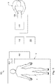
- a teleoperational medical system for use in, for example, medical procedures including diagnostic, therapeutic, or surgical procedures, is generally indicated by the reference numeral 100.
- the teleoperational medical systems of this disclosure are under the teleoperational control of a surgeon.
- a teleoperational medical system may be under the partial control of a computer programmed to perform the procedure or sub-procedure.
- a fully automated medical system under the full control of a computer programmed to perform the procedure or sub-procedure, may be used to perform procedures or sub-procedures.
- the teleoperational system 100 generally includes a teleoperational assembly 102 for operating a medical instrument system 104 in performing various procedures on the patient P.
- the assembly 102 is mounted to or near an operating table O on which a patient P is positioned.
- the medical instrument system 104 is operably coupled to the teleoperational assembly 102.
- An operator input system 106 allows a surgeon or other type of clinician S to view images of or representing the surgical site and to control the operation of the medical instrument system 104.
- the teleoperational system may include more than one manipulator assembly.
- the exact number of manipulator assemblies will depend on the surgical procedure and the space constraints within the operating room among other factors.
- the operator input system 106 may be located at a surgeon's console C, which is usually located in the same room as operating table O. However, it should be understood that the surgeon S can be located in a different room or a completely different building from the patient P.
- Operator input system 106 generally includes one or more control device(s) for controlling the medical instrument system 104.
- the control device(s) may include one or more of any number of a variety of input devices, such as hand grips, joysticks, trackballs, data gloves, trigger-guns, hand-operated controllers, voice recognition devices, touch screens, body motion or presence sensors, and the like.
- control device(s) will be provided with the same degrees of freedom as the medical instruments of the teleoperational assembly to provide the surgeon with telepresence, the perception that the control device(s) are integral with the instruments so that the surgeon has a strong sense of directly controlling instruments as if present at the surgical site.
- the control device(s) may have more or fewer degrees of freedom than the associated medical instruments and still provide the surgeon with telepresence.
- the control device(s) are manual input devices which move with six degrees of freedom, and which may also include an actuatable handle for actuating instruments (for example, for closing grasping jaws, applying an electrical potential to an electrode, delivering a medicinal treatment, and the like).
- the teleoperational assembly 102 supports the medical instrument system 104 and may include a kinematic structure of one or more non-servo controlled links (e.g., one or more links that may be manually positioned and locked in place, generally referred to as a set-up structure) and a teleoperational manipulator.
- the teleoperational assembly 102 includes plurality of actuators or motors that drive inputs on the medical instrument system 104 in response to commands from the control system (e.g., a control system 112).
- the motors include drive systems that when coupled to the medical instrument system 104 may advance the medical instrument into a naturally or surgically created anatomical orifice.
- motorized drive systems may move the distal end of the medical instrument in multiple degrees of freedom, which may include three degrees of linear motion (e.g., linear motion along the X, Y, Z Cartesian axes) and in three degrees of rotational motion (e.g., rotation about the X, Y, Z Cartesian axes). Additionally, the motors can be used to actuate an articulable end effector of the instrument for grasping tissue in the jaws of a biopsy device or the like.
- degrees of linear motion e.g., linear motion along the X, Y, Z Cartesian axes
- rotational motion e.g., rotation about the X, Y, Z Cartesian axes
- the teleoperational medical system 100 also includes a sensor system 108 with one or more sub-systems for receiving information about the instruments of the teleoperational assembly.
- a sensor system 108 with one or more sub-systems for receiving information about the instruments of the teleoperational assembly.
- Such sub-systems may include a position sensor system (e.g., an electromagnetic (EM) sensor system); a shape sensor system for determining the position, orientation, speed, velocity, pose, and/or shape of the catheter tip and/or of one or more segments along a flexible body of instrument system 104; and/or a visualization system for capturing images from the distal end of the catheter system.
- EM electromagnetic
- the visualization system may include a viewing scope assembly (described in greater detail below) such that a concurrent or real-time image of the surgical site is provided to the surgeon.
- the concurrent image may be, for example, a two or three dimensional image captured by an endoscope positioned within the surgical site.
- the visualization system includes endoscopic components that may be integrally or removably coupled to the medical instrument 104.
- a separate endoscope, attached to a separate manipulator assembly may be used with the medical instrument to image the surgical site.
- the visualization system may be implemented as hardware, firmware, software or a combination thereof which interact with or are otherwise executed by one or more computer processors, which may include the processors of a control system 112 (described below).
- the teleoperational medical system 100 also includes a display system 110 for displaying an image or representation of the surgical site and medical instrument system(s) 104 generated by sub-systems of the sensor system 108.
- the display 110 and the operator input system 106 may be oriented so the operator can control the medical instrument system 104 and the operator input system 106 with the perception of telepresence.
- the display system 110 may also display an image of the surgical site and medical instruments captured by the visualization system.
- the display 110 and the control devices may be oriented such that the relative positions of the imaging device in the scope assembly and the medical instruments are similar to the relative positions of the surgeon's eyes and hands so the operator can manipulate the medical instrument 104 and the hand control as if viewing the workspace in substantially true presence.
- true presence it is meant that the presentation of an image is a true perspective image simulating the viewpoint of an operator that is physically manipulating the instrument 104.
- the display 110 may present images of the surgical site recorded and/or modeled preoperatively using imaging technology such as, computed tomography (CT), magnetic resonance imaging (MRI), fluoroscopy, thermography, ultrasound, optical coherence tomography (OCT), thermal imaging, impedance imaging, laser imaging, or nanotube X-ray imaging.
- CT computed tomography
- MRI magnetic resonance imaging
- OCT optical coherence tomography
- the presented preoperative images may include two-dimensional, three-dimensional, or four-dimensional images.
- the presented preoperative or intra-operative images may include two-dimensional, three-dimensional, or four-dimensional (including e.g., time based or velocity based information) images and associated image data sets for reproducing the images.
- the display 110 may display a virtual navigational image in which the actual location of the medical instrument 104 is registered (i.e., dynamically referenced) with preoperative or concurrent images to present the surgeon S with a virtual image of the internal surgical site at the location of the tip of the instrument 104.
- An image of the tip of the instrument 104 or other graphical or alphanumeric indicators may be superimposed on the virtual image to assist the surgeon controlling the medical instrument.
- the instrument 104 may not be visible in the virtual image.
- the display 110 may display a virtual navigational image in which the actual location of the medical instrument is registered with preoperative or concurrent images to present the surgeon S with a virtual image of medical instrument within the surgical site from an external viewpoint.
- An image of a portion of the medical instrument or other graphical or alphanumeric indicators may be superimposed on the virtual image to assist the surgeon controlling the instrument 104.
- the teleoperational medical system 100 also includes a control system 112.
- the control system 112 includes at least one memory and at least one processor (not shown), and typically a plurality of processors, for effecting control between the medical instrument system 104, the operator input system 106, the sensor system 108, and the display system 110.
- the control system 112 also includes programmed instructions (e.g., a computer-readable medium storing the instructions) to implement some or all of the methods described in accordance with aspects disclosed herein. While control system 112 is shown as a single block in the simplified schematic of Fig.
- the system may include two or more data processing circuits with one portion of the processing optionally being performed on or adjacent the teleoperational assembly 102, another portion of the processing being performed at the operator input system 106, and the like. Any of a wide variety of centralized or distributed data processing architectures may be employed. Similarly, the programmed instructions may be implemented as a number of separate programs or subroutines, or they may be integrated into a number of other aspects of the teleoperational systems described herein. In one embodiment, control system 112 supports wireless communication protocols such as Bluetooth, IrDA, HomeRF, IEEE 802.11, DECT, and Wireless Telemetry.
- wireless communication protocols such as Bluetooth, IrDA, HomeRF, IEEE 802.11, DECT, and Wireless Telemetry.
- control system 112 may include one or more servo controllers that receive force and/or torque feedback from the medical instrument system 104. Responsive to the feedback, the servo controllers transmit signals to the operator input system 106. The servo controller(s) may also transmit signals instructing teleoperational assembly 102 to move the medical instrument system(s) 104 which extend into an internal surgical site within the patient body via openings in the body. Any suitable conventional or specialized servo controller may be used. A servo controller may be separate from, or integrated with, teleoperational assembly 102. In some embodiments, the servo controller and teleoperational assembly are provided as part of a teleoperational arm cart positioned adjacent to the patient's body.
- the control system 112 may further include a virtual visualization system to provide navigation assistance to the medical instrument system(s) 104.
- Virtual navigation using the virtual visualization system is based upon reference to an acquired dataset associated with the three dimensional structure of the anatomical passageways. More specifically, the virtual visualization system processes images of the surgical site imaged using imaging technology such as computerized tomography (CT), magnetic resonance imaging (MRI), fluoroscopy, thermography, ultrasound, optical coherence tomography (OCT), thermal imaging, impedance imaging, laser imaging, nanotube X-ray imaging, or the like.
- CT computerized tomography
- MRI magnetic resonance imaging
- fluoroscopy thermography
- ultrasound ultrasound
- OCT optical coherence tomography
- thermal imaging impedance imaging
- laser imaging laser imaging
- nanotube X-ray imaging or the like.
- An image data set is associated with the composite representation.
- the composite representation and the image data set describe the various locations and shapes of the passageways and their connectivity.
- the images used to generate the composite representation may be recorded preoperatively or intra-operatively during a clinical procedure.
- a virtual visualization system may use standard representations (i.e., not patient specific) or hybrids of a standard representation and patient specific data.
- the composite representation and any virtual images generated by the composite representation may represent the static posture of a deformable anatomic region during one or more phases of motion (e.g., during an inspiration/ expiration cycle of a lung).
- the sensor system 108 may be used to compute an approximate location of the instrument with respect to the patient anatomy.
- the location can be used to produce both macro-level tracking images of the patient anatomy and virtual internal images of the patient anatomy.
- Various systems for using fiber optic sensors to register and display a medical implement together with preoperatively recorded surgical images, such as those from a virtual visualization system are known.
- U.S. Patent Application No. 13/107,562 (filed May 13, 2011 )(disclosing "Medical System Providing Dynamic Registration of a Model of an Anatomical Structure for Image-Guided Surgery") published as US2012-0289777A1 , discloses one such system.
- the teleoperational medical system 100 may further include optional operation and support systems (not shown) such as illumination systems, steering control systems, irrigation systems, and/or suction systems.
- the teleoperational system may include more than one teleoperational assembly and/or more than one operator input system.
- the exact number of manipulator assemblies will depend on the surgical procedure and the space constraints within the operating room, among other factors.
- the operator input systems may be collocated, or they may be positioned in separate locations. Multiple operator input systems allow more than one operator to control one or more manipulator assemblies in various combinations.
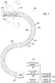
- FIG. 2 illustrates a medical instrument system 200, which may be used as the medical instrument system 104 of teleoperational medical system 100.
- the medical instrument system 200 may be used for non-teleoperational exploratory procedures or in procedures involving traditional manually operated medical instruments, such as endoscopy.
- the instrument system 200 includes a catheter system 202 coupled to an instrument body 204.
- the catheter system 202 includes an elongated flexible catheter body 216 having a proximal end 217 and a distal end or tip portion 218.
- the flexible body 216 has an approximately 3 mm outer diameter. Other flexible body outer diameters may be larger or smaller.
- the catheter system 202 may optionally include a shape sensor 222 for determining the position, orientation, speed, velocity, pose, and/or shape of the catheter tip at distal end 218 and/or of one or more segments 224 along the body 216. The entire length of the body 216, between the distal end 218 and the proximal end 217, may be effectively divided into the segments 224.
- the shape sensor 222 may be a component of the sensor system 108. If the instrument system 200 is manually operated or otherwise used for non-teleoperational procedures, the shape sensor 222 may be coupled to a tracking system 230 that interrogates the shape sensor and processes the received shape data.
- the shape sensor 222 may include an optical fiber aligned with the flexible catheter body 216 (e.g., provided within an interior channel (not shown) or mounted externally).
- the optical fiber has a diameter of approximately 200 ⁇ m. In other embodiments, the dimensions may be larger or smaller.
- the optical fiber of the shape sensor system 222 forms a fiber optic bend sensor for determining the shape of the catheter system 202.
- optical fibers including Fiber Bragg Gratings (FBGs) are used to provide strain measurements in structures in one or more dimensions.
- FBGs Fiber Bragg Gratings
- Various systems and methods for monitoring the shape and relative position of an optical fiber in three dimensions are described in U.S. Patent Application No. 11/180,389 (filed July 13, 2005 and published as US2006013523A1 ) (disclosing "Fiber optic position and shape sensing device and method relating thereto"); U.S. Patent Application No. 12/047,056 (filed on Jul.
- Sensors in alternative embodiments may employ other suitable strain sensing techniques, such as Rayleigh scattering, Raman scattering, Brillouin scattering, and Fluorescence scattering.
- the shape of the catheter may be determined using other techniques. For example, the history of the catheter's distal tip pose can be used to reconstruct the shape of the device over the interval of time.
- historical pose, position, or orientation data may be stored for a known point of an instrument system along a cycle of alternating motion, such as breathing. This stored data may be used to develop shape information about the catheter.
- a series of positional sensors, such as EM sensors, positioned along the catheter can be used for shape sensing.
- a history of data from a positional sensor, such as an EM sensor, on the instrument system during a procedure may be used to represent the shape of the instrument, particularly if an anatomical passageway is generally static.
- a wireless device with position or orientation controlled by an external magnetic field may be used for shape sensing. The history of the wireless device's position may be used to determine a shape for the navigated passageways.
- the optical fiber of the shape sensor 222 may be used to monitor the shape of at least a portion of the catheter system 202. More specifically, light passing through the optical fiber is processed to detect the shape of the catheter system 202 and to utilize that information to assist in surgical procedures.
- the sensor system e.g., sensor system 108
- the sensor system may include an interrogation system for generating and detecting the light used for determining the shape of the catheter system 202. This information, in turn, can be used to determine other related variables, such as velocity and acceleration of the parts of a medical instrument system.
- the sensing may be limited only to the degrees of freedom that are actuated by the teleoperational system, or it may be applied to both passive (e.g., unactuated bending of the rigid members between joints) and active (e.g., actuated movement of the instrument) degrees of freedom.
- the medical instrument system may optionally include a position sensor system 220.
- the position sensor system 220 may be a component of an EM sensor system with the sensor 220 including one or more conductive coils that may be subjected to an externally generated electromagnetic field. Each coil of the EM sensor system 220 then produces an induced electrical signal having characteristics that depend on the position and orientation of the coil relative to the externally generated electromagnetic field.
- the EM sensor system may be configured and positioned to measure six degrees of freedom, e.g., three position coordinates X, Y, Z and three orientation angles indicating pitch, yaw, and roll of a base point or five degrees of freedom, e.g., three position coordinates X, Y, Z and two orientation angles indicating pitch and yaw of a base point.
- six degrees of freedom e.g., three position coordinates X, Y, Z and three orientation angles indicating pitch, yaw, and roll of a base point
- five degrees of freedom e.g., three position coordinates X, Y, Z and two orientation angles indicating pitch and yaw of a base point.
- a tracking system 230 may include the position sensor system 220 and a shape sensor system 222 for determining the position, orientation, speed, pose, and/or shape of the distal end 218 and of one or more segments 224 along the instrument 200.
- the tracking system 230 may be implemented as hardware, firmware, software or a combination thereof which interact with or are otherwise executed by one or more computer processors, which may include the processors of a control system 116.
- the flexible catheter body 216 includes a channel sized and shaped to receive an auxiliary instrument 226.
- Auxiliary instruments may include, for example, image capture probes, biopsy instruments, laser ablation fibers, or other surgical, diagnostic, or therapeutic tools.
- Auxiliary tools may include end effectors having a single working member such as a scalpel, a blunt blade, an optical fiber, or an electrode.
- Other end effectors may include, for example, forceps, graspers, scissors, or clip appliers. Examples of electrically activated end effectors include electrosurgical electrodes, transducers, sensors, and the like.
- the auxiliary tool 226 may be an image capture probe that includes a distal portion with a stereoscopic or monoscopic camera at or near the distal end 218 of the flexible catheter body 216 for capturing images (including video images) that are processed by a visualization system 231 for display.
- the image capture probe may include a cable coupled to the camera for transmitting the captured image data.
- the image capture instrument may be a fiber-optic bundle, such as a fiberscope, that couples to the visualization system.
- the image capture instrument may be single or multi-spectral, for example capturing image data in one or more of the visible, infrared, or ultraviolet spectrums.
- the auxiliary instrument 226 may house cables, linkages, or other actuation controls (not shown) that extend between the proximal and distal ends of the instrument to controllably bend the distal end of the instrument.
- Steerable instruments are described in detail in U.S. Patent No. 7,316,681 (filed on Oct. 4, 2005 ) (disclosing "Articulated Surgical Instrument for Performing Minimally Invasive Surgery with Enhanced Dexterity and Sensitivity") and U.S. Patent Application No. 12/286,644 (filed Sept. 30, 2008 and published as US20100082041A1 ) (disclosing "Passive Preload and Capstan Drive for Surgical Instruments").
- the flexible catheter body 216 may also houses cables, linkages, or other steering controls (not shown) that extend between the housing 204 and the distal end 218 to controllably bend the distal end 218 as shown, for example, by the broken dashed line depictions 219 of the distal end.
- Steerable catheters are described in detail in U.S. Patent Application No. 13/274,208 (filed Oct. 14, 2011 and published as US20130096377 ) (disclosing "Catheter with Removable Vision Probe").
- the housing 204 may include drive inputs that removably couple to and receive power from motorized drive elements of the teleoperational assembly.
- the housing 204 may include gripping features, manual actuators, or other components for manually controlling the motion of the instrument system.
- the catheter system may be steerable or, alternatively, the system may be non-steerable with no integrated mechanism for operator control of the instrument bending.
- one or more lumens, through which medical instruments can be deployed and used at a target surgical location, are defined in the walls of the flexible body 216.
- the medical instrument system 200 may include a flexible bronchial instrument, such as a bronchoscope or bronchial catheter, for use in examination, diagnosis, biopsy, or treatment of a lung.
- a flexible bronchial instrument such as a bronchoscope or bronchial catheter
- the system 200 is also suited for navigation and treatment of other tissues, via natural or surgically created connected passageways, in any of a variety of anatomical systems, including the colon, the intestines, the kidneys, the brain, the heart, the circulatory system, and the like.
- the information from the tracking system 230 may be sent to a navigation system 232 where it is combined with information from the visualization system 231 and/or the preoperatively obtained models to provide the surgeon or other operator with real-time position information on the display system 110 for use in the control of the instrument 200.
- the control system 116 may utilize the position information as feedback for positioning the instrument 200.
- Various systems for using fiber optic sensors to register and display a surgical instrument with surgical images are provided in U.S. Patent Application No. 13/107,562, filed May 13, 2011 , published as US20120289777A1 , disclosing, "Medical System Providing Dynamic Registration of a Model of an Anatomical Structure for Image-Guided Surgery.”
- the instrument 200 is teleoperated within the teleoperational medical system 100.
- the teleoperational assembly 102 may be replaced by direct operator control.
- various handles and operator interfaces may be included for hand-held operation of the instrument.
- Fig. 3 depicts a display system 150 (e.g., the display system 110) providing a composite image of an anatomic model 151 of a human lung 152, from a viewpoint external to the lung. Such an image shows an illustrative path through anatomic passageways 156 to a target location 153.
- the model lung 151 is registered with an instrument image 154 of a flexible instrument, such as catheter system 202.
- FIG. 4A provides a flowchart 400 illustrating a process for generating a composite image such as the composite image of FIG. 3 .
- a pre- or intra-operative image e.g., CT or MRI
- a model of the anatomy may be generated from the set of images using a modeling function such as a segmentation process.
- a modeling function such as a segmentation process.
- the images are partitioned into segments or elements (e.g., pixels or voxels) that share certain characteristics or computed properties such as color, density, intensity, and texture.
- This segmentation process results in a two- or three-dimensional reconstruction that forms a model of the target anatomy based on the obtained image.
- the segmentation process may delineate sets of voxels representing the target anatomy and then apply a function, such as marching cube function, to obtain a 3D surface that encloses the voxels.
- an operator or an automated control system may plan a path through the model to a target structure or region (e.g., a tumor or an occlusion).
- a target structure or region e.g., a tumor or an occlusion
- the path planning process may occur and reoccur at various stages in the procedure 400.
- the model is registered to the patient anatomy. More specifically, the 3D surface that encloses the voxels may be dynamically referenced to the patient anatomy.
- the model has a frame of reference and an associated model coordinate system.
- the model frame of reference is registered to a patient frame of reference so that the locations of anatomic structures identified in the model can be transformed to the patient frame of reference in which the actual patient and interventional instrument exist.
- the instrument is localized with respect to the patient anatomy. More specifically, the instrument tracking system (e.g. system 230) tracks the location of the instrument relative to the patient anatomy as the instrument moves through the anatomy. The tracking system may track the location of a portion of the tool such as a distal end of the tool. More than one location on the instrument may be tracked.
- the tracked instrument is registered with the anatomic model and, optionally, a displayed image is generated as shown in FIG. 3 . More specifically, the location, orientation, shape, movement, or other spatial reference data for the interventional instrument in the patient frame of reference can be matched and transformed to the model frame of reference so that the movement of the instrument with respect to the modeled anatomic structures can be tracked and displayed.
- ICP Iterative Closest Point
- ICP is a technique whereby a first set of spatial reference points is transformed with respect to a second set of points such that the total sum difference between corresponding points is reduced. The transformation is iteratively revised such that the two sets of points are at a minimal distance from each other.
- the first set of points corresponds to points or spatial data information that represent the model.
- the second set of points corresponds to points or spatial data records obtained from various types of tracking systems associated with the instrument.
- the spatial data records obtained from the tracking systems may provide information about the time or order in which the record was created and may include position, orientation, shape, movement or other spatial information about the instrument.
- the points obtained from the instrument are updated due to movement of the instrument, the second set of points in space is iteratively transformed with respect to the first set of points from the model.
- the instrument stays registered with the model as the instrument navigates the passageway toward the target in process 414.
- the accuracy of the instrument localization and registration is increased as more spatial information about the instrument in received.
- receiving redundant or inaccurate spatial information about the location of the instrument may reduce the accuracy of the localization or may slow the localization process.
- inconsistent spatial data records may be obtained due to irregularities in the sensor systems of the tracking system. If these outlier data points are used to compute localization and registration, the results may be inaccurate.
- spatial data records are being obtained at specific time intervals and the instrument becomes stopped, there may be an large set of spatial data records for a particular anatomical area. This can cause the ICP function to give undue weight to that area and can increase error in the registration process.
- the set of spatial data records obtained from an instrument's tracking system can be filtered such that certain records are removed or given a lower weight when used for ICP or other registration techniques. Filtering may also include selecting for analysis only spatial data records that satisfy a criterion. It is understood, however, that the techniques described herein are not limited to use in registration but may be used for other purposes such as building or modifying a model by tracking movement of the instrument through the anatomic passageways. The filtering may be done in a variety of ways as will be described herein.
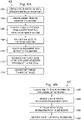
- Fig. 4B is a flowchart showing an illustrative method 450 for performing a registration using filtered data.
- a set of spatial information is received from a model of the patient anatomy.
- This set of spatial information may include a set of elements corresponding to passageways in the patient anatomy.
- the elements may be represented, for example, as voxels, passageway centerline points, or a mesh model.
- the set of spatial information from the model may also include a three-dimensional surface that surrounds the voxels.
- a set of spatial information is obtained from the instrument tracking system.
- This set of spatial information may be a set of spatial data records obtained from the tracking system providing information about the time or order in which consecutive records were created and may include position, orientation, shape, movement or other spatial information about the instrument.
- the set of spatial information from the tracking system is filtered by selecting, removing, or providing a weighting factor to the spatial data records that are deemed to be redundant, outliers, of a lower confidence or quality, from an undesirable time period (e.g., too old or too new), obtained during a certain cycle of cyclic anatomical motion, associated with a deformed shape, or other reasons that may cause a particular spatial data record or subset of spatial data records to be objectionable or preferable.
- the filtered set of spatial data records from the tracking system and the spatial information from the model may be registered.
- an image of the instrument registered to the anatomy may be displayed.
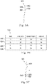
- FIG. 5A illustrates a set 500 of points including points in space that correspond to spatial data records 502, 504, 506, 508 obtained from an instrument (e.g. instrument system 200).
- FIG. 5B illustrates a table 510 of the spatial data records 502, 504, 506, 508.
- the spatial data records may be obtained, for example, from a sensor (e.g. an EM sensor) located on a distal portion of the instrument.
- Each spatial data record provides spatial information about the distal portion of the instrument at various times.
- spatial data record 502 describes the position PI and orientation O1 of the distal end of the instrument at a time T1.
- a weighting factor W1 may be associated with the spatial data record 502. The weighting factors may be applied after a filtering process is performed for the set of data.
- a weight W1 of 1 may indicate that the spatial data record 502 is usable or not otherwise objectionable for purposes of registration.
- a weight W1 of 0 may indicate that the spatial data record 502 is discarded or not to be used in registration of the instrument.
- a weight W1 between 0 and 1 may be applied if the confidence level in the spatial data record 502 is uncertain or low.
- the record 502 would be considered in a registration algorithm but would not be weighted as strongly as records that had a strong confidence level and a weight of 1.
- a record 504 is obtained at a time T2, consecutive to the time T1, and is associated with the new position P2 and orientation O2 for the instrument.
- the spatial data record 502 may include other fields including shape data, velocity data, motor torque, force, or other spatial information for the instrument at the time T1.
- a set of spatial information obtained from the instrument may include spatial data records that contribute to inaccuracies when using the full set of records for registration or model building.
- Various techniques for filtering spatial data records obtained from an instrument may be used in registration or modeling procedures. Any one or a combination of the filtering methods described below may be used to filter spatial data records.
- the spatial data records may be filtered by discarding or applying a reduced weighting factor records that are redundant to records that were previously obtained and that thus do not provide additional spatial information.
- FIG. 5C illustrates a set 520 of points in space that correspond to spatial data records including records 522, 524, 526, 528, and 530 obtained from an instrument (e.g. instrument system 200). Applying a filtering process to the set 520 may cause the records 528 and 530 to be recognized as redundant (e.g. providing the same or similar spatial information) of record 526. Redundant data records may occur when records are obtained at regular time intervals but the instrument movement has backtracked or stalled within the anatomic passageway due to, for example, instrument size (e.g.
- Redundancy may be determined in a variety of different ways. In one embodiment, redundancy may be based upon a spatial relationship between spatial data records that correspond to a variety of voxels or other spatial containers. For example, as shown in FIG. 6A , an anatomic model may be comprised of a plurality of elements represented, for example, by a set of voxels 601 (e.g. a voxel map) that correspond to an imaged and segmented anatomic passageway.
- a set of voxels 601 e.g. a voxel map
- Each spatial data record in a set 600 of spatial data records obtained from an instrument may be associated with or matched to a voxel in the set of voxels 601.
- the voxel map can be used to track which areas of three-dimensional space have been sampled to obtain spatial data records.
- a voxel 608 in the voxel map 601 may be associated with a plurality 604 of obtained spatial data records. If the number of spatial data records associated with a single voxel exceeds a threshold value, which may be any value greater than one, the extra spatial records may be filtered by being discarded (e.g., give a weighting value of zero) or by being provided with a low weighting value (e.g., less than one). Alternatively, the weighted or unweighted spatial data records associated with the single voxel may be averaged.
- redundancy may be based upon a spatial relationship such as a measured distance between the data records.
- redundancy may be determined by ordering a plurality of spatial data records in collection time-gathered order. For example, as shown in FIG. 6B , a distance D1 between a first consecutive spatial data record 610 and a second consecutive spatial data record 612 may be measured. If the distance D1 is below a threshold value (e.g. too close), the second consecutive record 612 may be considered redundant of the first value 610.
- One of the first or second consecutive records therefore, may be filtered by being discarded (e.g., give a weighting value of zero) or provided with a low weighting value (e.g., less than one). This process of evaluating consecutive records may be optimized using a k-dimensional tree analysis.
- the spatial data records may be filtered by discarding, applying a reduced weighting factor, or selecting records based upon the teleoperational commanded position, orientation, or velocity of the instrument.
- the commanded position of the instrument provides an indicator of the expected distance to be traveled by the instrument during a particular time period.
- a commanded velocity may be based upon the commanded position and a commanded time period for reaching that commanded position (e.g., difference in commanded position/ time period).
- a commanded velocity profile 700 may be provided for a medical procedure using an instrument as described above. For a time period T1, the instrument is commanded to move at a velocity V1. For a time period T2, the instrument is commanded to move at a slower velocity V2.
- the instrument may be in transition between velocities V1 and V2.
- the commanded velocity profile is generated from movement of an operator input device at an operation input system (e.g., system 106).
- the quantity of spatial data records to be selected by the filter is set.
- the filter selects a quantity of spatial data records proportionate to the commanded velocity profile. For example, if the instrument is moving quickly (e.g., V1), the quantity of spatial data records set to be selected (Q1) by the filter during the period of movement may be larger than the quantity selected (Q2) by the filter during the same period of movement if the instrument is moving slowly (e.g., V2).
- the filtering may continue at a proportionate rate or may be temporarily terminated until a constant velocity is reached again.
- the commanded position filtering technique may be modified so that the filter algorithm does not select spatial data records obtained if movement of the instrument is stalled or does not select spatial data records at a particular stage of cyclic anatomical motion.
- the instrument may be provided with a force sensor which can detect if the distal end of the instrument is in contact with tissue that may impede or prevent motion. If a signal from the force sensor indicates that the instrument has encountered an obstruction, the filter algorithm may adjust to a state in which no spatial data records are selected for use in registration or model-building.
- instruments may be provided with force, position, orientation or other sensors that are used to detect cyclical anatomical motion (e.g., respiration, cardiac motion) or gross movements of the patient.
- the filtering algorithm may select spatial data records for analysis when the motion is minimized (e.g., at a full inspiration state of respiration). Similar to FIG. 7 , commanded position and orientation profiles may be used filter spatial data records.
- Spatial data records may also be filtered based upon forces measured on the instrument and/or associated motor torques for driving movement of the instrument. For example, if the measured motor torque is greater than an expected threshold value for creating a particular pose, the data associated with the excessive motor torque may be discarded.
- the spatial data records may be filtered by discarding, applying a reduced weighting factor, or selecting records based upon whether or not a spatial data record is identified as an outlier record.
- FIG. 8 illustrates a set 750 of points in space that correspond to spatial data records including records 752, 754, 756 obtained from an instrument (e.g. instrument system 200). Applying a filtering process to the set 750 may cause record 754 to become recognized as an outlier data point.
- An outlier point may be caused by variability in the EM sensor, cyclical anatomic motion (e.g., respiration) or other patient movement, operator steering inconsistencies, instrument characteristics such as flexibility or lack of flexibility.
- the record 754 may therefore be weighted with a zero or a value near zero to minimize the use of that record in an instrument registration process.
- the data record 754 may be identified as an outlier based upon a quality metric for the sensor (e.g., an EM sensor) that is providing the position or orientation information.
- Sensor quality metrics may be provide an indication of the accuracy of the sensor.
- a six degree of freedom EM sensor may be comprised of two five degree of freedom EM sensors mounted at an angle relative to each other. If the overlapping degrees of freedom are not consistent with each other, a quality metric associated with the sensor may be determined to be low or poor.
- optical fiber accuracy may be a function of the tightness of the fiber bend proximate to the region of interest. If the bend is determined to be very tight, data from that region and regions distal of the bend may be discarded or discounted. Sensor noise may also be used to determine sensor accuracy for a particular time at which the data is recorded.
- the data record 754 may be identified as an outlier based upon the distance in position or change in orientation from a predecessor or to a successor data record in view of the estimated speed of the instrument movement. For example, a distance 758 between record 754 and a subsequent consecutive record 756 and a distance 760 between record 754 and a prior consecutive record 752 may be measured. If the distances 758 and 760 are greater than an expected distance based upon the maximum velocity of the instrument, the record 754 may be identified as an outlier. Alternatively, if the distances 758 and 760 are greater than an expected distance based upon the velocity of the instrument before and after the record 754 was recorded, the record 754 may be identified as an outlier.
- the record 754 may be identified as an outlier.
- the orientations between the instrument for record 704 compared to preceding record 752 and subsequent record 756 may be measured. If the orientation differences are substantially different from the average orientation differences between other records in the set 750, the record 754 may be identified as an outlier.
- the spatial data records may be filtered by discarding, applying a reduced weighting factor, or selecting records based upon a confidence value for each spatial data record. Records with low confidence values may be filtered out of the data set more aggressively.
- a confidence value may be determined for each spatial data record based upon an amount of variation in the signal received from the sensors or on the instrument. For example, large variations in orientation of the instrument distal end as determined from the received signal may cause the spatial data points to be given a low confidence value. If the variations in orientation of the instrument distal end are small, the spatial data points may be given a higher confidence value.
- a set of data records 800 includes spatial data records for points 802, 804, and 806.
- Each spatial data record 802, 804, 806 includes an orientation value O 802 , O 804 , O 806 , respectively. If analysis indicates that the orientation O 806 is significantly different from the previous and subsequent orientation values O 802 , O 804 , the data record 806 may be discarded or provided with a lower weight value.
- the spatial data points may be given a low confidence value. If the variation in distance is smaller, the spatial data points may be given a higher confidence value. If confidence values for a set of spatial data records fall below a threshold value, the low confidence may be accommodated by averaging the records in the set. Confidence values may also be used with the voxel map described above. As an example, for all of the records associated with a particular element or voxel, the data records may be weighted by confidence value and the weighted records may be averaged.
- the orientations may be evaluated.
- the amount of variability may correlate to the size of the lumen of the anatomic passageway. In other words, if the variability is large, the lumen may be large because the instrument distal end is able to approach a location from multiple directions. If the variability is small, the lumen may be small because the tight passageway limits the angulation of the distal end of the instrument. Large lumens may be associated with lower confidence values. If records with low confidence values must be selected to obtain sufficient records to perform a registration process, the low confidence records may be averaged or a median record may be selected by the filter.
- the spatial data records may be filtered by discarding, applying a reduced weighting factor, or selecting records based upon temporal information for each spatial data record. For example, older records (e.g., spatial data records with early time values compared to other spatial data records) may be discarded or given a lower weighting value. If the surgical procedure is likely to cause deformation, the older spatial data records from an earlier undeformed state of the anatomy may be preferred. In that case, newer records (e.g. spatial data records with later time values compared to other spatial data records) may be discarded or given a lower weighting value.
- spatial data records for selected times in a cyclic anatomical motion cycle may be selected by the filter.
- the records may be provided with weighted values based upon the amount of time that has passed since the selected time.
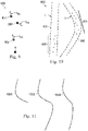
- FIG. 10 illustrates a set of spatial data records 900 including records 902 and 904.
- An anatomic passageway 906 is shown in an undeformed state U and a deformed state D of cyclic anatomical motion.
- the filtering algorithm may be set to select the record 902 for a time associated with the undeformed state rather than a record 904 for a time associated with the deformed state.
- the spatial data records may be filtered by discarding, applying a reduced weighting factor, or selecting records based upon whether the spatial data record is associated with anatomic deformation.
- This technique may be particularly suitable when using filtering to build a deformed model or determining how to register the deformed anatomy to a pre-operative, undeformed model.
- a shape sensor extending within the instrument positioned within an anatomic passageway may return an undeformed shape profile 1000. If the anatomic passageway is undeformed by the instrument or other forces on the passageway, further advancement of the instrument and shape sensor will return a shape profile 1002 which includes the shape from the shape profile 1000.
- the anatomic passageway is deformed by the instrument or other forces on the passageway, further advancement of the instrument and shape sensor will return a deformed shape profile 1004.
- the deformation of the passageway as observed by the shape profiles may be used to determine whether to filter spatial data records obtained by the instrument. For example, if a model of the undeformed anatomy is being built from the spatial data records, data records obtained while the instrument is in the deformed profile 1004 may be filtered out of the data set. If a model of the deformed anatomy is of interest, data records obtained while the instrument is in the deformed profile 104 may be preserved or selected while spatial data records associated with the shape profile 1002 may be filtered out.
- the systems and methods of this disclosure may be used for connected bronchial passageways of the lung.
- the systems and methods may also be suited for navigation and treatment of other tissues, via natural or surgically created connected passageways, in any of a variety of anatomical systems including the colon, the intestines, the kidneys, the brain, the heart, the circulatory system, or the like.
- the systems and methods may also be suitable for navigation around the traceable surface of an organ.
- the methods and embodiments of this disclosure are also suitable for non-surgical applications.
- One or more elements in embodiments of the invention may be implemented in software to execute on a processor of a computer system such as control processing system 112.
- the elements of the embodiments of the invention are essentially the code segments to perform the necessary tasks.
- the program or code segments can be stored in a processor readable storage medium or device that may have been downloaded by way of a computer data signal embodied in a carrier wave over a transmission medium or a communication link.
- the processor readable storage device may include any medium that can store information including an optical medium, semiconductor medium, and magnetic medium.
- Processor readable storage device examples include an electronic circuit; a semiconductor device, a semiconductor memory device, a read only memory (ROM), a flash memory, an erasable programmable read only memory (EPROM); a floppy diskette, a CD-ROM, an optical disk, a hard disk, or other storage device,
- the code segments may be downloaded via computer networks such as the Internet, Intranet, etc.
Claims (8)
- Système comprenant :un instrument médical (104, 200) configuré pour être déplacé par un ensemble d'actionnement à distance (102) ;un système d'entrée d'opération comprenant un dispositif d'entrée d'opérateur ; etune unité de traitement (112) comprenant un ou plusieurs processeurs, l'unité de traitement étant configurée pour :fournir des instructions à l'ensemble d'actionnement à distance pour déplacer l'instrument dans un passage anatomique selon un profil de vitesse commandé généré à partir du mouvement du dispositif d'entrée d'opérateur au système d'entrée d'opération ;recevoir un ensemble d'informations spatiales de l'instrument positionné à l'intérieur du passage anatomique ; etfiltrer l'ensemble d'informations spatiales pour sélectionner une quantité d'enregistrements de données spatiales à partir de l'ensemble d'informations spatiales proportionnelles aux vitesses du profil de vitesse commandé, les vitesses étant associées à des périodes de temps pendant lesquelles les enregistrements de données spatiales sont collectés.
- Système selon la revendication 1, dans lequel les informations spatiales comprennent des informations de position.
- Système selon la revendication 1, dans lequel les informations spatiales comprennent des informations d'orientation.
- Système selon la revendication 1, dans lequel l'instrument médical comprend un capteur électromagnétique (220) qui suit les informations spatiales.
- Système selon la revendication 1, dans lequel les vitesses du profil de vitesse commandé comprennent une première vitesse commandée et une seconde vitesse commandée supérieure à la première vitesse et dans lequel le filtrage de l'ensemble d'informations spatiales comprend la sélection de moins d'enregistrements de données spatiales pendant une première période de temps pour la première vitesse que pendant une seconde période de temps pour la seconde vitesse.
- Système selon la revendication 1, dans lequel l'unité de traitement est en outre configurée pour :recevoir un ensemble d'informations spatiales de modèle pour un modèle du passage anatomique etenregistrer la quantité sélectionnée d'enregistrements de données spatiales à partir de l'ensemble d'informations spatiales vers l'ensemble d'informations spatiales de modèle.
- Système selon la revendication 1, dans lequel l'unité de traitement est en outre configurée pour :recevoir un signal à partir d'un capteur de force ; etterminer la réception de l'ensemble d'informations spatiales provenant de l'instrument sur la base du signal reçu provenant du capteur de force.
- Système selon la revendication 1, dans lequel l'instrument médical comprend un capteur de forme de fibre optique (222) et l'ensemble d'informations spatiales provenant de l'instrument est reçu à partir du capteur de forme de fibre optique.
Priority Applications (1)
| Application Number | Priority Date | Filing Date | Title |
|---|---|---|---|
| EP22201322.9A EP4140432A1 (fr) | 2014-11-13 | 2015-11-11 | Systèmes et procédés de filtrage de données de localisation |
Applications Claiming Priority (2)
| Application Number | Priority Date | Filing Date | Title |
|---|---|---|---|
| US201462079139P | 2014-11-13 | 2014-11-13 | |
| PCT/US2015/060083 WO2016077419A1 (fr) | 2014-11-13 | 2015-11-11 | Systèmes et procédés de filtration de données de localisation |
Related Child Applications (2)
| Application Number | Title | Priority Date | Filing Date |
|---|---|---|---|
| EP22201322.9A Division-Into EP4140432A1 (fr) | 2014-11-13 | 2015-11-11 | Systèmes et procédés de filtrage de données de localisation |
| EP22201322.9A Division EP4140432A1 (fr) | 2014-11-13 | 2015-11-11 | Systèmes et procédés de filtrage de données de localisation |
Publications (3)
| Publication Number | Publication Date |
|---|---|
| EP3217911A1 EP3217911A1 (fr) | 2017-09-20 |
| EP3217911A4 EP3217911A4 (fr) | 2018-07-11 |
| EP3217911B1 true EP3217911B1 (fr) | 2023-01-04 |
Family
ID=55954972
Family Applications (2)
| Application Number | Title | Priority Date | Filing Date |
|---|---|---|---|
| EP15858691.7A Active EP3217911B1 (fr) | 2014-11-13 | 2015-11-11 | Systèmes de filtration de données de localisation |
| EP22201322.9A Pending EP4140432A1 (fr) | 2014-11-13 | 2015-11-11 | Systèmes et procédés de filtrage de données de localisation |
Family Applications After (1)
| Application Number | Title | Priority Date | Filing Date |
|---|---|---|---|
| EP22201322.9A Pending EP4140432A1 (fr) | 2014-11-13 | 2015-11-11 | Systèmes et procédés de filtrage de données de localisation |
Country Status (6)
| Country | Link |
|---|---|
| US (3) | US20170325896A1 (fr) |
| EP (2) | EP3217911B1 (fr) |
| JP (2) | JP7017931B2 (fr) |
| KR (2) | KR102540633B1 (fr) |
| CN (1) | CN107111684A (fr) |
| WO (1) | WO2016077419A1 (fr) |
Families Citing this family (80)
| Publication number | Priority date | Publication date | Assignee | Title |
|---|---|---|---|---|
| US8218847B2 (en) | 2008-06-06 | 2012-07-10 | Superdimension, Ltd. | Hybrid registration method |
| US8672837B2 (en) | 2010-06-24 | 2014-03-18 | Hansen Medical, Inc. | Methods and devices for controlling a shapeable medical device |
| US10039473B2 (en) * | 2012-05-14 | 2018-08-07 | Intuitive Surgical Operations, Inc. | Systems and methods for navigation based on ordered sensor records |
| US9057600B2 (en) | 2013-03-13 | 2015-06-16 | Hansen Medical, Inc. | Reducing incremental measurement sensor error |
| US9014851B2 (en) | 2013-03-15 | 2015-04-21 | Hansen Medical, Inc. | Systems and methods for tracking robotically controlled medical instruments |
| US9271663B2 (en) | 2013-03-15 | 2016-03-01 | Hansen Medical, Inc. | Flexible instrument localization from both remote and elongation sensors |
| US9629595B2 (en) | 2013-03-15 | 2017-04-25 | Hansen Medical, Inc. | Systems and methods for localizing, tracking and/or controlling medical instruments |
| US11020016B2 (en) | 2013-05-30 | 2021-06-01 | Auris Health, Inc. | System and method for displaying anatomy and devices on a movable display |
| US9633431B2 (en) | 2014-07-02 | 2017-04-25 | Covidien Lp | Fluoroscopic pose estimation |
| US9603668B2 (en) | 2014-07-02 | 2017-03-28 | Covidien Lp | Dynamic 3D lung map view for tool navigation inside the lung |
| US9901406B2 (en) | 2014-10-02 | 2018-02-27 | Inneroptic Technology, Inc. | Affected region display associated with a medical device |
| US9974525B2 (en) | 2014-10-31 | 2018-05-22 | Covidien Lp | Computed tomography enhanced fluoroscopic system, device, and method of utilizing the same |
| US20170325896A1 (en) | 2014-11-13 | 2017-11-16 | Intuitive Surgical Operations, Inc. | Systems and methods for filtering localization data |
| US10188467B2 (en) | 2014-12-12 | 2019-01-29 | Inneroptic Technology, Inc. | Surgical guidance intersection display |
| US10548564B2 (en) * | 2015-02-26 | 2020-02-04 | Rivanna Medical, LLC | System and method for ultrasound imaging of regions containing bone structure |
| US9949700B2 (en) * | 2015-07-22 | 2018-04-24 | Inneroptic Technology, Inc. | Medical device approaches |
| US10716525B2 (en) | 2015-08-06 | 2020-07-21 | Covidien Lp | System and method for navigating to target and performing procedure on target utilizing fluoroscopic-based local three dimensional volume reconstruction |
| US10674982B2 (en) | 2015-08-06 | 2020-06-09 | Covidien Lp | System and method for local three dimensional volume reconstruction using a standard fluoroscope |
| US10702226B2 (en) | 2015-08-06 | 2020-07-07 | Covidien Lp | System and method for local three dimensional volume reconstruction using a standard fluoroscope |
| AU2016323982A1 (en) | 2015-09-18 | 2018-04-12 | Auris Health, Inc. | Navigation of tubular networks |
| US10143526B2 (en) | 2015-11-30 | 2018-12-04 | Auris Health, Inc. | Robot-assisted driving systems and methods |
| US10529088B2 (en) * | 2016-12-02 | 2020-01-07 | Gabriel Fine | Automatically determining orientation and position of medically invasive devices via image processing |
| US10244926B2 (en) | 2016-12-28 | 2019-04-02 | Auris Health, Inc. | Detecting endolumenal buckling of flexible instruments |
| EP3576662A4 (fr) * | 2017-02-01 | 2020-12-23 | Intuitive Surgical Operations Inc. | Systèmes et procédés de filtrage de données issues de données de capteurs de passage |
| US11517184B2 (en) | 2017-02-01 | 2022-12-06 | Intuitive Surgical Operations, Inc. | Systems and methods of registration for image-guided procedures |
| US11793579B2 (en) | 2017-02-22 | 2023-10-24 | Covidien Lp | Integration of multiple data sources for localization and navigation |
| US11490782B2 (en) | 2017-03-31 | 2022-11-08 | Auris Health, Inc. | Robotic systems for navigation of luminal networks that compensate for physiological noise |
| JP2020520691A (ja) * | 2017-05-12 | 2020-07-16 | オーリス ヘルス インコーポレイテッド | 生検装置およびシステム |
| US10022192B1 (en) | 2017-06-23 | 2018-07-17 | Auris Health, Inc. | Automatically-initialized robotic systems for navigation of luminal networks |
| WO2019005696A1 (fr) | 2017-06-28 | 2019-01-03 | Auris Health, Inc. | Détection de distorsion électromagnétique |
| CN116725667A (zh) | 2017-06-28 | 2023-09-12 | 奥瑞斯健康公司 | 提供定位信息的系统和在解剖结构内定位器械的方法 |
| US10699448B2 (en) | 2017-06-29 | 2020-06-30 | Covidien Lp | System and method for identifying, marking and navigating to a target using real time two dimensional fluoroscopic data |
| CN116869664A (zh) * | 2017-08-10 | 2023-10-13 | 直观外科手术操作公司 | 远程手术系统的增加的可用器械寿命 |
| CN111163697B (zh) | 2017-10-10 | 2023-10-03 | 柯惠有限合伙公司 | 用于在荧光三维重构中识别和标记目标的系统和方法 |
| US11058493B2 (en) | 2017-10-13 | 2021-07-13 | Auris Health, Inc. | Robotic system configured for navigation path tracing |
| US10555778B2 (en) | 2017-10-13 | 2020-02-11 | Auris Health, Inc. | Image-based branch detection and mapping for navigation |
| US10341456B2 (en) * | 2017-11-20 | 2019-07-02 | Marc Berger | Caching sticker profiles within a sticker communication system |
| CN110869173B (zh) | 2017-12-14 | 2023-11-17 | 奥瑞斯健康公司 | 用于估计器械定位的系统与方法 |
| JP7059377B2 (ja) | 2017-12-18 | 2022-04-25 | オーリス ヘルス インコーポレイテッド | 管腔ネットワーク内の器具の追跡およびナビゲーションの方法およびシステム |
| CN108469429B (zh) * | 2018-02-06 | 2020-11-24 | 西安电子科技大学 | 一种双模态拉曼-光学投影断层成像系统 |
| US10905498B2 (en) | 2018-02-08 | 2021-02-02 | Covidien Lp | System and method for catheter detection in fluoroscopic images and updating displayed position of catheter |
| US11364004B2 (en) | 2018-02-08 | 2022-06-21 | Covidien Lp | System and method for pose estimation of an imaging device and for determining the location of a medical device with respect to a target |
| US10930064B2 (en) | 2018-02-08 | 2021-02-23 | Covidien Lp | Imaging reconstruction system and method |
| MX2020010112A (es) * | 2018-03-28 | 2020-11-06 | Auris Health Inc | Sistemas y metodos para el registro de sensores de ubicacion. |
| JP7225259B2 (ja) | 2018-03-28 | 2023-02-20 | オーリス ヘルス インコーポレイテッド | 器具の推定位置を示すためのシステム及び方法 |
| EP3773301B1 (fr) | 2018-04-13 | 2024-03-06 | Karl Storz SE & Co. KG | Système de guidage et logiciel associé |
| US10872449B2 (en) | 2018-05-02 | 2020-12-22 | Covidien Lp | System and method for constructing virtual radial ultrasound images from CT data and performing a surgical navigation procedure using virtual ultrasound images |
| WO2019231895A1 (fr) | 2018-05-30 | 2019-12-05 | Auris Health, Inc. | Systèmes et procédés destinés à la prédiction d'emplacement de branche basé sur capteur |
| US10898275B2 (en) * | 2018-05-31 | 2021-01-26 | Auris Health, Inc. | Image-based airway analysis and mapping |
| EP3801280A4 (fr) | 2018-05-31 | 2022-03-09 | Auris Health, Inc. | Systèmes robotiques et procédés de navigation d'un réseau luminal qui détectent le bruit physiologique |
| EP3801189A4 (fr) | 2018-05-31 | 2022-02-23 | Auris Health, Inc. | Navigation basée sur trajet de réseaux tubulaires |
| US20210259783A1 (en) * | 2018-06-19 | 2021-08-26 | Intuitive Surgical Operations, Inc. | Systems and Methods Related to Registration for Image Guided Surgery |
| US11071591B2 (en) | 2018-07-26 | 2021-07-27 | Covidien Lp | Modeling a collapsed lung using CT data |
| US11705238B2 (en) | 2018-07-26 | 2023-07-18 | Covidien Lp | Systems and methods for providing assistance during surgery |
| US11944388B2 (en) | 2018-09-28 | 2024-04-02 | Covidien Lp | Systems and methods for magnetic interference correction |
| US11877806B2 (en) | 2018-12-06 | 2024-01-23 | Covidien Lp | Deformable registration of computer-generated airway models to airway trees |
| US11045075B2 (en) | 2018-12-10 | 2021-06-29 | Covidien Lp | System and method for generating a three-dimensional model of a surgical site |
| US11801113B2 (en) | 2018-12-13 | 2023-10-31 | Covidien Lp | Thoracic imaging, distance measuring, and notification system and method |
| US11617493B2 (en) | 2018-12-13 | 2023-04-04 | Covidien Lp | Thoracic imaging, distance measuring, surgical awareness, and notification system and method |
| US11357593B2 (en) | 2019-01-10 | 2022-06-14 | Covidien Lp | Endoscopic imaging with augmented parallax |
| US11625825B2 (en) | 2019-01-30 | 2023-04-11 | Covidien Lp | Method for displaying tumor location within endoscopic images |
| US11925333B2 (en) | 2019-02-01 | 2024-03-12 | Covidien Lp | System for fluoroscopic tracking of a catheter to update the relative position of a target and the catheter in a 3D model of a luminal network |
| US11564751B2 (en) | 2019-02-01 | 2023-01-31 | Covidien Lp | Systems and methods for visualizing navigation of medical devices relative to targets |
| US11744643B2 (en) | 2019-02-04 | 2023-09-05 | Covidien Lp | Systems and methods facilitating pre-operative prediction of post-operative tissue function |
| US11819285B2 (en) | 2019-04-05 | 2023-11-21 | Covidien Lp | Magnetic interference detection systems and methods |
| US11269173B2 (en) | 2019-08-19 | 2022-03-08 | Covidien Lp | Systems and methods for displaying medical video images and/or medical 3D models |
| EP4021331A4 (fr) * | 2019-08-30 | 2023-08-30 | Auris Health, Inc. | Systèmes et procédés permettant le recalage de capteurs de position sur la base de poids |
| CN114340540B (zh) | 2019-08-30 | 2023-07-04 | 奥瑞斯健康公司 | 器械图像可靠性系统和方法 |
| CN114641252B (zh) | 2019-09-03 | 2023-09-01 | 奥瑞斯健康公司 | 电磁畸变检测和补偿 |
| US11864935B2 (en) | 2019-09-09 | 2024-01-09 | Covidien Lp | Systems and methods for pose estimation of a fluoroscopic imaging device and for three-dimensional imaging of body structures |
| US11931111B2 (en) | 2019-09-09 | 2024-03-19 | Covidien Lp | Systems and methods for providing surgical guidance |
| US11627924B2 (en) | 2019-09-24 | 2023-04-18 | Covidien Lp | Systems and methods for image-guided navigation of percutaneously-inserted devices |
| EP4084720A4 (fr) | 2019-12-31 | 2024-01-17 | Auris Health Inc | Techniques d'alignement pour un accès percutané |
| EP4084721A4 (fr) | 2019-12-31 | 2024-01-03 | Auris Health Inc | Identification et ciblage d'éléments anatomiques |
| WO2021137108A1 (fr) | 2019-12-31 | 2021-07-08 | Auris Health, Inc. | Interfaces d'alignement pour accès percutané |
| US11847730B2 (en) | 2020-01-24 | 2023-12-19 | Covidien Lp | Orientation detection in fluoroscopic images |
| US11380060B2 (en) | 2020-01-24 | 2022-07-05 | Covidien Lp | System and method for linking a segmentation graph to volumetric data |
| US11701492B2 (en) | 2020-06-04 | 2023-07-18 | Covidien Lp | Active distal tip drive |
| US11950950B2 (en) | 2020-07-24 | 2024-04-09 | Covidien Lp | Zoom detection and fluoroscope movement detection for target overlay |
| US20220202500A1 (en) * | 2020-12-30 | 2022-06-30 | Canon U.S.A., Inc. | Intraluminal navigation using ghost instrument information |
Family Cites Families (24)
| Publication number | Priority date | Publication date | Assignee | Title |
|---|---|---|---|---|
| FR2567149B1 (fr) | 1984-07-06 | 1986-12-05 | Solvay | Procede pour l'extraction de poly-beta-hydroxybutyrates au moyen d'un solvant a partir d'une suspension aqueuse de micro-organismes |
| US5792135A (en) | 1996-05-20 | 1998-08-11 | Intuitive Surgical, Inc. | Articulated surgical instrument for performing minimally invasive surgery with enhanced dexterity and sensitivity |
| WO1998036236A1 (fr) | 1997-02-13 | 1998-08-20 | Super Dimension Ltd. | Systeme de poursuite a six degres |
| GB9713018D0 (en) | 1997-06-20 | 1997-08-27 | Secr Defence | Optical fibre bend sensor |
| US6584465B1 (en) | 2000-02-25 | 2003-06-24 | Eastman Kodak Company | Method and system for search and retrieval of similar patterns |
| US7772541B2 (en) | 2004-07-16 | 2010-08-10 | Luna Innnovations Incorporated | Fiber optic position and/or shape sensing based on rayleigh scatter |
| US20060013523A1 (en) | 2004-07-16 | 2006-01-19 | Luna Innovations Incorporated | Fiber optic position and shape sensing device and method relating thereto |
| US7824328B2 (en) * | 2006-09-18 | 2010-11-02 | Stryker Corporation | Method and apparatus for tracking a surgical instrument during surgery |
| US7894871B2 (en) * | 2006-12-29 | 2011-02-22 | St. Jude Medical, Atrial Fibrillation Division, Inc. | Filtering method for surface modeling |
| US20100030063A1 (en) * | 2008-07-31 | 2010-02-04 | Medtronic, Inc. | System and method for tracking an instrument |
| US9259274B2 (en) | 2008-09-30 | 2016-02-16 | Intuitive Surgical Operations, Inc. | Passive preload and capstan drive for surgical instruments |
| DE102009030731A1 (de) * | 2009-06-26 | 2010-12-30 | Fiagon Gmbh | Verfahren zum Erzeugen von Positionsdaten eines Instrumentes |
| US8668638B2 (en) * | 2010-02-11 | 2014-03-11 | Intuitive Surgical Operations, Inc. | Method and system for automatically maintaining an operator selected roll orientation at a distal tip of a robotic endoscope |
| EP2599033B1 (fr) * | 2010-07-29 | 2021-03-31 | Sync-RX, Ltd. | Utilisation conjointe de données endoluminales et d'imagerie extraluminale |
| WO2012109760A1 (fr) * | 2011-02-18 | 2012-08-23 | Traumis Surgical Systems Inc. | Outil comportant un système de navigation et de guidage intégré et appareil et procédés associés |
| US8900131B2 (en) * | 2011-05-13 | 2014-12-02 | Intuitive Surgical Operations, Inc. | Medical system providing dynamic registration of a model of an anatomical structure for image-guided surgery |
| US8827934B2 (en) * | 2011-05-13 | 2014-09-09 | Intuitive Surgical Operations, Inc. | Method and system for determining information of extrema during expansion and contraction cycles of an object |
| US9452276B2 (en) | 2011-10-14 | 2016-09-27 | Intuitive Surgical Operations, Inc. | Catheter with removable vision probe |
| WO2013126659A1 (fr) * | 2012-02-22 | 2013-08-29 | Veran Medical Technologies, Inc. | Systèmes, procédés et dispositifs pour une navigation à quatre dimensions dans un tissu mou |
| US10039473B2 (en) * | 2012-05-14 | 2018-08-07 | Intuitive Surgical Operations, Inc. | Systems and methods for navigation based on ordered sensor records |
| US20140180063A1 (en) * | 2012-10-12 | 2014-06-26 | Intuitive Surgical Operations, Inc. | Determining position of medical device in branched anatomical structure |
| US9820677B2 (en) * | 2013-01-03 | 2017-11-21 | St. Jude Medical, Atrial Fibrillation Division, Inc. | Cointegration filter for a catheter navigation system |
| US10912523B2 (en) | 2014-03-24 | 2021-02-09 | Intuitive Surgical Operations, Inc. | Systems and methods for anatomic motion compensation |
| US20170325896A1 (en) | 2014-11-13 | 2017-11-16 | Intuitive Surgical Operations, Inc. | Systems and methods for filtering localization data |
-
2015
- 2015-11-11 US US15/525,909 patent/US20170325896A1/en not_active Abandoned
- 2015-11-11 WO PCT/US2015/060083 patent/WO2016077419A1/fr active Application Filing
- 2015-11-11 JP JP2017525882A patent/JP7017931B2/ja active Active
- 2015-11-11 EP EP15858691.7A patent/EP3217911B1/fr active Active
- 2015-11-11 KR KR1020227025357A patent/KR102540633B1/ko active IP Right Grant
- 2015-11-11 KR KR1020177015643A patent/KR102425170B1/ko active IP Right Grant
- 2015-11-11 EP EP22201322.9A patent/EP4140432A1/fr active Pending
- 2015-11-11 CN CN201580073033.1A patent/CN107111684A/zh active Pending
-
2020
- 2020-02-26 US US16/802,109 patent/US11791032B2/en active Active
- 2020-04-10 JP JP2020070786A patent/JP7296341B2/ja active Active
-
2023
- 2023-09-08 US US18/463,624 patent/US20230420107A1/en active Pending
Also Published As
| Publication number | Publication date |
|---|---|
| JP7296341B2 (ja) | 2023-06-22 |
| EP3217911A4 (fr) | 2018-07-11 |
| CN107111684A (zh) | 2017-08-29 |
| US20170325896A1 (en) | 2017-11-16 |
| JP2020168374A (ja) | 2020-10-15 |
| EP3217911A1 (fr) | 2017-09-20 |
| JP7017931B2 (ja) | 2022-02-09 |
| KR20170083093A (ko) | 2017-07-17 |
| JP2017535341A (ja) | 2017-11-30 |
| WO2016077419A1 (fr) | 2016-05-19 |
| US11791032B2 (en) | 2023-10-17 |
| US20200188038A1 (en) | 2020-06-18 |
| KR102425170B1 (ko) | 2022-07-26 |
| US20230420107A1 (en) | 2023-12-28 |
| KR102540633B1 (ko) | 2023-06-07 |
| KR20220112849A (ko) | 2022-08-11 |
| EP4140432A1 (fr) | 2023-03-01 |
Similar Documents
| Publication | Publication Date | Title |
|---|---|---|
| US11791032B2 (en) | Systems and methods for filtering localization data | |
| US11896364B2 (en) | Systems and methods for registration of multiple vision systems | |
| US11957424B2 (en) | Systems and methods for planning multiple interventional procedures | |
| US20220378316A1 (en) | Systems and methods for intraoperative segmentation | |
| US20200107899A1 (en) | Systems and methods for adaptive input mapping | |
| CN106170265B (zh) | 用于介入工具的虚拟导航的组织的非刚性变形的系统和方法 | |
| US20210259783A1 (en) | Systems and Methods Related to Registration for Image Guided Surgery | |
| US20220142714A1 (en) | Systems for enhanced registration of patient anatomy |
Legal Events
| Date | Code | Title | Description |
|---|---|---|---|
| STAA | Information on the status of an ep patent application or granted ep patent |
Free format text: STATUS: THE INTERNATIONAL PUBLICATION HAS BEEN MADE |
|
| PUAI | Public reference made under article 153(3) epc to a published international application that has entered the european phase |
Free format text: ORIGINAL CODE: 0009012 |
|
| STAA | Information on the status of an ep patent application or granted ep patent |
Free format text: STATUS: REQUEST FOR EXAMINATION WAS MADE |
|
| 17P | Request for examination filed |
Effective date: 20170609 |
|
| AK | Designated contracting states |
Kind code of ref document: A1 Designated state(s): AL AT BE BG CH CY CZ DE DK EE ES FI FR GB GR HR HU IE IS IT LI LT LU LV MC MK MT NL NO PL PT RO RS SE SI SK SM TR |
|
| AX | Request for extension of the european patent |
Extension state: BA ME |
|
| DAV | Request for validation of the european patent (deleted) | ||
| DAX | Request for extension of the european patent (deleted) | ||
| A4 | Supplementary search report drawn up and despatched |
Effective date: 20180612 |
|
| RIC1 | Information provided on ipc code assigned before grant |
Ipc: A61B 34/00 20160101AFI20180606BHEP Ipc: A61B 90/00 20160101ALN20180606BHEP Ipc: A61B 34/10 20160101ALN20180606BHEP Ipc: A61B 34/35 20160101ALN20180606BHEP Ipc: A61B 34/30 20160101ALI20180606BHEP Ipc: G06F 19/00 20110101ALI20180606BHEP Ipc: A61B 34/20 20160101ALI20180606BHEP |
|
| STAA | Information on the status of an ep patent application or granted ep patent |
Free format text: STATUS: EXAMINATION IS IN PROGRESS |
|
| 17Q | First examination report despatched |
Effective date: 20210412 |
|
| STAA | Information on the status of an ep patent application or granted ep patent |
Free format text: STATUS: EXAMINATION IS IN PROGRESS |
|
| GRAP | Despatch of communication of intention to grant a patent |
Free format text: ORIGINAL CODE: EPIDOSNIGR1 |
|
| STAA | Information on the status of an ep patent application or granted ep patent |
Free format text: STATUS: GRANT OF PATENT IS INTENDED |
|
| RIC1 | Information provided on ipc code assigned before grant |
Ipc: A61B 34/10 20160101ALN20220114BHEP Ipc: A61B 34/35 20160101ALN20220114BHEP Ipc: A61B 90/00 20160101ALN20220114BHEP Ipc: G16H 40/63 20180101ALI20220114BHEP Ipc: G16H 30/40 20180101ALI20220114BHEP Ipc: G16H 20/40 20180101ALI20220114BHEP Ipc: A61B 34/30 20160101ALI20220114BHEP Ipc: A61B 34/20 20160101ALI20220114BHEP Ipc: A61B 34/00 20160101AFI20220114BHEP |
|
| INTG | Intention to grant announced |
Effective date: 20220131 |
|
| GRAJ | Information related to disapproval of communication of intention to grant by the applicant or resumption of examination proceedings by the epo deleted |
Free format text: ORIGINAL CODE: EPIDOSDIGR1 |
|
| STAA | Information on the status of an ep patent application or granted ep patent |
Free format text: STATUS: EXAMINATION IS IN PROGRESS |
|
| GRAP | Despatch of communication of intention to grant a patent |
Free format text: ORIGINAL CODE: EPIDOSNIGR1 |
|
| STAA | Information on the status of an ep patent application or granted ep patent |
Free format text: STATUS: GRANT OF PATENT IS INTENDED |
|
| INTC | Intention to grant announced (deleted) | ||
| RIC1 | Information provided on ipc code assigned before grant |
Ipc: A61B 34/10 20160101ALN20220608BHEP Ipc: A61B 34/35 20160101ALN20220608BHEP Ipc: A61B 90/00 20160101ALN20220608BHEP Ipc: G16H 40/63 20180101ALI20220608BHEP Ipc: G16H 30/40 20180101ALI20220608BHEP Ipc: G16H 20/40 20180101ALI20220608BHEP Ipc: A61B 34/30 20160101ALI20220608BHEP Ipc: A61B 34/20 20160101ALI20220608BHEP Ipc: A61B 34/00 20160101AFI20220608BHEP |
|
| INTG | Intention to grant announced |
Effective date: 20220701 |
|
| GRAS | Grant fee paid |
Free format text: ORIGINAL CODE: EPIDOSNIGR3 |
|
| GRAA | (expected) grant |
Free format text: ORIGINAL CODE: 0009210 |
|
| STAA | Information on the status of an ep patent application or granted ep patent |
Free format text: STATUS: THE PATENT HAS BEEN GRANTED |
|
| AK | Designated contracting states |
Kind code of ref document: B1 Designated state(s): AL AT BE BG CH CY CZ DE DK EE ES FI FR GB GR HR HU IE IS IT LI LT LU LV MC MK MT NL NO PL PT RO RS SE SI SK SM TR |
|
| REG | Reference to a national code |
Ref country code: GB Ref legal event code: FG4D |
|
| REG | Reference to a national code |
Ref country code: DE Ref legal event code: R096 Ref document number: 602015082200 Country of ref document: DE |
|
| REG | Reference to a national code |
Ref country code: CH Ref legal event code: EP |
|
| REG | Reference to a national code |
Ref country code: AT Ref legal event code: REF Ref document number: 1541413 Country of ref document: AT Kind code of ref document: T Effective date: 20230115 |
|
| REG | Reference to a national code |
Ref country code: IE Ref legal event code: FG4D |
|
| REG | Reference to a national code |
Ref country code: LT Ref legal event code: MG9D |
|
| REG | Reference to a national code |
Ref country code: NL Ref legal event code: MP Effective date: 20230104 |
|
| P01 | Opt-out of the competence of the unified patent court (upc) registered |
Effective date: 20230428 |
|
| REG | Reference to a national code |
Ref country code: AT Ref legal event code: MK05 Ref document number: 1541413 Country of ref document: AT Kind code of ref document: T Effective date: 20230104 |
|
| PG25 | Lapsed in a contracting state [announced via postgrant information from national office to epo] |
Ref country code: NL Free format text: LAPSE BECAUSE OF FAILURE TO SUBMIT A TRANSLATION OF THE DESCRIPTION OR TO PAY THE FEE WITHIN THE PRESCRIBED TIME-LIMIT Effective date: 20230104 |
|
| PG25 | Lapsed in a contracting state [announced via postgrant information from national office to epo] |
Ref country code: RS Free format text: LAPSE BECAUSE OF FAILURE TO SUBMIT A TRANSLATION OF THE DESCRIPTION OR TO PAY THE FEE WITHIN THE PRESCRIBED TIME-LIMIT Effective date: 20230104 Ref country code: PT Free format text: LAPSE BECAUSE OF FAILURE TO SUBMIT A TRANSLATION OF THE DESCRIPTION OR TO PAY THE FEE WITHIN THE PRESCRIBED TIME-LIMIT Effective date: 20230504 Ref country code: NO Free format text: LAPSE BECAUSE OF FAILURE TO SUBMIT A TRANSLATION OF THE DESCRIPTION OR TO PAY THE FEE WITHIN THE PRESCRIBED TIME-LIMIT Effective date: 20230404 Ref country code: LV Free format text: LAPSE BECAUSE OF FAILURE TO SUBMIT A TRANSLATION OF THE DESCRIPTION OR TO PAY THE FEE WITHIN THE PRESCRIBED TIME-LIMIT Effective date: 20230104 Ref country code: LT Free format text: LAPSE BECAUSE OF FAILURE TO SUBMIT A TRANSLATION OF THE DESCRIPTION OR TO PAY THE FEE WITHIN THE PRESCRIBED TIME-LIMIT Effective date: 20230104 Ref country code: HR Free format text: LAPSE BECAUSE OF FAILURE TO SUBMIT A TRANSLATION OF THE DESCRIPTION OR TO PAY THE FEE WITHIN THE PRESCRIBED TIME-LIMIT Effective date: 20230104 Ref country code: ES Free format text: LAPSE BECAUSE OF FAILURE TO SUBMIT A TRANSLATION OF THE DESCRIPTION OR TO PAY THE FEE WITHIN THE PRESCRIBED TIME-LIMIT Effective date: 20230104 Ref country code: AT Free format text: LAPSE BECAUSE OF FAILURE TO SUBMIT A TRANSLATION OF THE DESCRIPTION OR TO PAY THE FEE WITHIN THE PRESCRIBED TIME-LIMIT Effective date: 20230104 |
|
| PG25 | Lapsed in a contracting state [announced via postgrant information from national office to epo] |
Ref country code: SE Free format text: LAPSE BECAUSE OF FAILURE TO SUBMIT A TRANSLATION OF THE DESCRIPTION OR TO PAY THE FEE WITHIN THE PRESCRIBED TIME-LIMIT Effective date: 20230104 Ref country code: PL Free format text: LAPSE BECAUSE OF FAILURE TO SUBMIT A TRANSLATION OF THE DESCRIPTION OR TO PAY THE FEE WITHIN THE PRESCRIBED TIME-LIMIT Effective date: 20230104 Ref country code: IS Free format text: LAPSE BECAUSE OF FAILURE TO SUBMIT A TRANSLATION OF THE DESCRIPTION OR TO PAY THE FEE WITHIN THE PRESCRIBED TIME-LIMIT Effective date: 20230504 Ref country code: GR Free format text: LAPSE BECAUSE OF FAILURE TO SUBMIT A TRANSLATION OF THE DESCRIPTION OR TO PAY THE FEE WITHIN THE PRESCRIBED TIME-LIMIT Effective date: 20230405 Ref country code: FI Free format text: LAPSE BECAUSE OF FAILURE TO SUBMIT A TRANSLATION OF THE DESCRIPTION OR TO PAY THE FEE WITHIN THE PRESCRIBED TIME-LIMIT Effective date: 20230104 |
|
| REG | Reference to a national code |
Ref country code: DE Ref legal event code: R097 Ref document number: 602015082200 Country of ref document: DE |
|
| PG25 | Lapsed in a contracting state [announced via postgrant information from national office to epo] |
Ref country code: SM Free format text: LAPSE BECAUSE OF FAILURE TO SUBMIT A TRANSLATION OF THE DESCRIPTION OR TO PAY THE FEE WITHIN THE PRESCRIBED TIME-LIMIT Effective date: 20230104 Ref country code: RO Free format text: LAPSE BECAUSE OF FAILURE TO SUBMIT A TRANSLATION OF THE DESCRIPTION OR TO PAY THE FEE WITHIN THE PRESCRIBED TIME-LIMIT Effective date: 20230104 Ref country code: EE Free format text: LAPSE BECAUSE OF FAILURE TO SUBMIT A TRANSLATION OF THE DESCRIPTION OR TO PAY THE FEE WITHIN THE PRESCRIBED TIME-LIMIT Effective date: 20230104 Ref country code: DK Free format text: LAPSE BECAUSE OF FAILURE TO SUBMIT A TRANSLATION OF THE DESCRIPTION OR TO PAY THE FEE WITHIN THE PRESCRIBED TIME-LIMIT Effective date: 20230104 Ref country code: CZ Free format text: LAPSE BECAUSE OF FAILURE TO SUBMIT A TRANSLATION OF THE DESCRIPTION OR TO PAY THE FEE WITHIN THE PRESCRIBED TIME-LIMIT Effective date: 20230104 |
|
| PLBE | No opposition filed within time limit |
Free format text: ORIGINAL CODE: 0009261 |
|
| STAA | Information on the status of an ep patent application or granted ep patent |
Free format text: STATUS: NO OPPOSITION FILED WITHIN TIME LIMIT |
|
| PG25 | Lapsed in a contracting state [announced via postgrant information from national office to epo] |
Ref country code: SK Free format text: LAPSE BECAUSE OF FAILURE TO SUBMIT A TRANSLATION OF THE DESCRIPTION OR TO PAY THE FEE WITHIN THE PRESCRIBED TIME-LIMIT Effective date: 20230104 |
|
| 26N | No opposition filed |
Effective date: 20231005 |
|
| PG25 | Lapsed in a contracting state [announced via postgrant information from national office to epo] |
Ref country code: SI Free format text: LAPSE BECAUSE OF FAILURE TO SUBMIT A TRANSLATION OF THE DESCRIPTION OR TO PAY THE FEE WITHIN THE PRESCRIBED TIME-LIMIT Effective date: 20230104 |
|
| PGFP | Annual fee paid to national office [announced via postgrant information from national office to epo] |
Ref country code: DE Payment date: 20231127 Year of fee payment: 9 |