EP3978754B1 - Spiralverdichter - Google Patents
Spiralverdichter Download PDFInfo
- Publication number
- EP3978754B1 EP3978754B1 EP20812649.0A EP20812649A EP3978754B1 EP 3978754 B1 EP3978754 B1 EP 3978754B1 EP 20812649 A EP20812649 A EP 20812649A EP 3978754 B1 EP3978754 B1 EP 3978754B1
- Authority
- EP
- European Patent Office
- Prior art keywords
- compression cavity
- intermediate compression
- scroll
- end plate
- fluid
- Prior art date
- Legal status (The legal status is an assumption and is not a legal conclusion. Google has not performed a legal analysis and makes no representation as to the accuracy of the status listed.)
- Active
Links
Images


Classifications
-
- F—MECHANICAL ENGINEERING; LIGHTING; HEATING; WEAPONS; BLASTING
- F04—POSITIVE - DISPLACEMENT MACHINES FOR LIQUIDS; PUMPS FOR LIQUIDS OR ELASTIC FLUIDS
- F04C—ROTARY-PISTON, OR OSCILLATING-PISTON, POSITIVE-DISPLACEMENT MACHINES FOR LIQUIDS; ROTARY-PISTON, OR OSCILLATING-PISTON, POSITIVE-DISPLACEMENT PUMPS
- F04C18/00—Rotary-piston pumps specially adapted for elastic fluids
- F04C18/02—Rotary-piston pumps specially adapted for elastic fluids of arcuate-engagement type, i.e. with circular translatory movement of co-operating members, each member having the same number of teeth or tooth-equivalents
- F04C18/0207—Rotary-piston pumps specially adapted for elastic fluids of arcuate-engagement type, i.e. with circular translatory movement of co-operating members, each member having the same number of teeth or tooth-equivalents both members having co-operating elements in spiral form
- F04C18/0215—Rotary-piston pumps specially adapted for elastic fluids of arcuate-engagement type, i.e. with circular translatory movement of co-operating members, each member having the same number of teeth or tooth-equivalents both members having co-operating elements in spiral form where only one member is moving
-
- F—MECHANICAL ENGINEERING; LIGHTING; HEATING; WEAPONS; BLASTING
- F04—POSITIVE - DISPLACEMENT MACHINES FOR LIQUIDS; PUMPS FOR LIQUIDS OR ELASTIC FLUIDS
- F04C—ROTARY-PISTON, OR OSCILLATING-PISTON, POSITIVE-DISPLACEMENT MACHINES FOR LIQUIDS; ROTARY-PISTON, OR OSCILLATING-PISTON, POSITIVE-DISPLACEMENT PUMPS
- F04C18/00—Rotary-piston pumps specially adapted for elastic fluids
- F04C18/02—Rotary-piston pumps specially adapted for elastic fluids of arcuate-engagement type, i.e. with circular translatory movement of co-operating members, each member having the same number of teeth or tooth-equivalents
- F04C18/0207—Rotary-piston pumps specially adapted for elastic fluids of arcuate-engagement type, i.e. with circular translatory movement of co-operating members, each member having the same number of teeth or tooth-equivalents both members having co-operating elements in spiral form
- F04C18/0246—Details concerning the involute wraps or their base, e.g. geometry
- F04C18/0253—Details concerning the base
-
- F—MECHANICAL ENGINEERING; LIGHTING; HEATING; WEAPONS; BLASTING
- F04—POSITIVE - DISPLACEMENT MACHINES FOR LIQUIDS; PUMPS FOR LIQUIDS OR ELASTIC FLUIDS
- F04C—ROTARY-PISTON, OR OSCILLATING-PISTON, POSITIVE-DISPLACEMENT MACHINES FOR LIQUIDS; ROTARY-PISTON, OR OSCILLATING-PISTON, POSITIVE-DISPLACEMENT PUMPS
- F04C28/00—Control of, monitoring of, or safety arrangements for, pumps or pumping installations specially adapted for elastic fluids
- F04C28/10—Control of, monitoring of, or safety arrangements for, pumps or pumping installations specially adapted for elastic fluids characterised by changing the positions of the inlet or outlet openings with respect to the working chamber
-
- F—MECHANICAL ENGINEERING; LIGHTING; HEATING; WEAPONS; BLASTING
- F04—POSITIVE - DISPLACEMENT MACHINES FOR LIQUIDS; PUMPS FOR LIQUIDS OR ELASTIC FLUIDS
- F04C—ROTARY-PISTON, OR OSCILLATING-PISTON, POSITIVE-DISPLACEMENT MACHINES FOR LIQUIDS; ROTARY-PISTON, OR OSCILLATING-PISTON, POSITIVE-DISPLACEMENT PUMPS
- F04C28/00—Control of, monitoring of, or safety arrangements for, pumps or pumping installations specially adapted for elastic fluids
- F04C28/24—Control of, monitoring of, or safety arrangements for, pumps or pumping installations specially adapted for elastic fluids characterised by using valves controlling pressure or flow rate, e.g. discharge valves or unloading valves
-
- F—MECHANICAL ENGINEERING; LIGHTING; HEATING; WEAPONS; BLASTING
- F04—POSITIVE - DISPLACEMENT MACHINES FOR LIQUIDS; PUMPS FOR LIQUIDS OR ELASTIC FLUIDS
- F04C—ROTARY-PISTON, OR OSCILLATING-PISTON, POSITIVE-DISPLACEMENT MACHINES FOR LIQUIDS; ROTARY-PISTON, OR OSCILLATING-PISTON, POSITIVE-DISPLACEMENT PUMPS
- F04C29/00—Component parts, details or accessories of pumps or pumping installations, not provided for in groups F04C18/00 - F04C28/00
- F04C29/12—Arrangements for admission or discharge of the working fluid, e.g. constructional features of the inlet or outlet
- F04C29/124—Arrangements for admission or discharge of the working fluid, e.g. constructional features of the inlet or outlet with inlet and outlet valves specially adapted for rotary or oscillating piston pumps
- F04C29/126—Arrangements for admission or discharge of the working fluid, e.g. constructional features of the inlet or outlet with inlet and outlet valves specially adapted for rotary or oscillating piston pumps of the non-return type
-
- F—MECHANICAL ENGINEERING; LIGHTING; HEATING; WEAPONS; BLASTING
- F04—POSITIVE - DISPLACEMENT MACHINES FOR LIQUIDS; PUMPS FOR LIQUIDS OR ELASTIC FLUIDS
- F04C—ROTARY-PISTON, OR OSCILLATING-PISTON, POSITIVE-DISPLACEMENT MACHINES FOR LIQUIDS; ROTARY-PISTON, OR OSCILLATING-PISTON, POSITIVE-DISPLACEMENT PUMPS
- F04C18/00—Rotary-piston pumps specially adapted for elastic fluids
- F04C18/02—Rotary-piston pumps specially adapted for elastic fluids of arcuate-engagement type, i.e. with circular translatory movement of co-operating members, each member having the same number of teeth or tooth-equivalents
- F04C18/0207—Rotary-piston pumps specially adapted for elastic fluids of arcuate-engagement type, i.e. with circular translatory movement of co-operating members, each member having the same number of teeth or tooth-equivalents both members having co-operating elements in spiral form
- F04C18/0246—Details concerning the involute wraps or their base, e.g. geometry
- F04C18/0253—Details concerning the base
- F04C18/0261—Details of the ports, e.g. location, number, geometry
-
- F—MECHANICAL ENGINEERING; LIGHTING; HEATING; WEAPONS; BLASTING
- F04—POSITIVE - DISPLACEMENT MACHINES FOR LIQUIDS; PUMPS FOR LIQUIDS OR ELASTIC FLUIDS
- F04C—ROTARY-PISTON, OR OSCILLATING-PISTON, POSITIVE-DISPLACEMENT MACHINES FOR LIQUIDS; ROTARY-PISTON, OR OSCILLATING-PISTON, POSITIVE-DISPLACEMENT PUMPS
- F04C23/00—Combinations of two or more pumps, each being of rotary-piston or oscillating-piston type, specially adapted for elastic fluids; Pumping installations specially adapted for elastic fluids; Multi-stage pumps specially adapted for elastic fluids
- F04C23/008—Hermetic pumps
-
- F—MECHANICAL ENGINEERING; LIGHTING; HEATING; WEAPONS; BLASTING
- F04—POSITIVE - DISPLACEMENT MACHINES FOR LIQUIDS; PUMPS FOR LIQUIDS OR ELASTIC FLUIDS
- F04C—ROTARY-PISTON, OR OSCILLATING-PISTON, POSITIVE-DISPLACEMENT MACHINES FOR LIQUIDS; ROTARY-PISTON, OR OSCILLATING-PISTON, POSITIVE-DISPLACEMENT PUMPS
- F04C28/00—Control of, monitoring of, or safety arrangements for, pumps or pumping installations specially adapted for elastic fluids
- F04C28/10—Control of, monitoring of, or safety arrangements for, pumps or pumping installations specially adapted for elastic fluids characterised by changing the positions of the inlet or outlet openings with respect to the working chamber
- F04C28/14—Control of, monitoring of, or safety arrangements for, pumps or pumping installations specially adapted for elastic fluids characterised by changing the positions of the inlet or outlet openings with respect to the working chamber using rotating valves
Definitions
- the present disclosure relates to the technical field of scroll compressor, and in particular to a scroll compressor with function of variable volume ratio.
- Compressors may be used in application systems that require different pressures, such as air-conditioning systems, refrigeration systems, etc. Therefore, there may be cases where the discharge pressure of the compression chamber (the maximum pressure in the compression chamber) is higher than the pressure required by a specific application system, that is, there may be over-compression. In the case of over-compression, the discharge pressure of the compressed fluid is reduced to the pressure required by the application system after it is discharged from the compression chamber, so the compressor does unnecessary work, which may reduce the efficiency of the compressor.
- VVR variable volume ratio
- EP0972942A2 in an abstract states that "A scroll compressor has an economizer injection line communicating into the scroll compressor chambers. An unloader valve selectively communicates the economizer injection line back to suction. In this arrangement, the fluid ports and passages necessary to achieve the economizer injection are also utilized to achieve suction bypass unloading, and thus the compressor and system design and construction are simplified.”
- the invention in a machine translation of an abstract states that "The invention relates to a scroll compressor, which includes: an orbiting scroll (60), a fixed scroll (100) and a cover plate (120) fitted on the fixed scroll end plate (104). At least one pressure relief hole (110) selectively communicated with at least one of the compression chambers is formed in 104), and the pressure relief hole (110) passes through the communication space between the fixed scroll end plate (104) and the cover plate (120) (S) is in fluid communication with the exhaust port (102) on the fixed scroll.
- the scroll compressor of the present invention can significantly reduce the over-compression phenomenon and has a relatively low cost.”
- a compressor including: a stationary volute and a moving volute each including a plate provided with a scroll, said scrolls defining variable-volume compression chambers; a delivery line provided in the plate of the stationary volute; a delivery port arranged such as to establish a communication between the delivery line and a delivery chamber; and a non-return device including (i) a valve seat surrounding the delivery port and (ii) a delivery valve which can move between delivery port opening and closing positions.
- the compressor includes: at least one bypass passage having a first end opening into the delivery line at a point between the central compression chamber and the valve seat and a second end opening into an intermediate compression chamber or into a low-pressure portion of the compressor, and at least one bypass valve which can move between bypass passage closing and opening positions.”
- An object of one or more embodiments of the present disclosure is to provide a compressor having a variable volume ratio mechanism that is not restricted by the installation space and has a simple structure.
- Another object of one or more embodiments of the present disclosure is to provide a compressor having a variable volume ratio mechanism suitable for a small displacement compressor provided with a fixed scroll hub.
- Another object of one or more embodiments of the present disclosure is to provide a compressor having a variable volume ratio mechanism that is highly compatible and can be realized in a simple and quick manner.
- Another object of one or more embodiments of the present disclosure is to provide a compressor having a variable volume ratio mechanism that requires fewer new parts to be developed, and therefore has low development difficulty at high development speed.
- Another object of one or more embodiments of the present disclosure is to provide a compressor having a variable volume ratio mechanism that can operate reliably with no split design, no cover plate, and low leakage.
- a scroll compressor including: a movable scroll including a movable scroll end plate and a movable volute formed on one side of the movable scroll end plate; and a fixed scroll including a fixed scroll end plate and a fixed volute formed on one side of the fixed scroll end plate, wherein the fixed scroll and the movable scroll are engaged to form a series of compression cavities therebetween.
- the series of compression cavities include a central compression cavity and intermediate compression cavities located radially outside of the central compression cavity.
- the intermediate compression cavities includes at least a set of a first intermediate compression cavity and a second intermediate compression cavity with a fluid channel provided therebetween for selectively communicating with a discharge area, and the first intermediate compression cavity and the second intermediate compression cavity are directly communicated through the fluid channel.
- the scroll compressor includes: a main discharge port and an auxiliary discharge port provided at the fixed scroll end plate.
- the main discharge port is in fluid communication with the central compression cavity, and the auxiliary discharge port is shared by the first intermediate compression cavity and the second intermediate compression cavity to be selectively in fluid communication with the discharge area.
- the fluid channel includes a first section communicating with the first intermediate compression cavity, a second section communicating with the second intermediate compression cavity, and a connecting section connecting the first section and the second section.
- the fluid channel is arranged in the fixed scroll end plate.
- the connecting section includes a first connecting section communicating with the first section and a second connecting section communicating with the second section.
- the first connecting section and the second connecting section intersect.
- the auxiliary discharge port is in direct fluid communication with one of the first intermediate compression cavity and the second intermediate compression cavity.
- the fluid channel is provided in the movable scroll end plate, and the connecting section is formed as a single section.
- the auxiliary discharge port is in direct fluid communication with one of the first intermediate compression cavity and the second intermediate compression cavity.
- the connecting section has a first end penetrating the fixed scroll end plate or the movable scroll end plate, and a plug for preventing fluid leakage is provided at the first end.
- the fluid channel is provided on at least one of the fixed volute and the movable volute.
- the fluid channel includes a trench provided on the end surface of the free end of the fixed volute and/or the movable volute, and a first slot and a second slot extending from the trench and communicating with the first intermediate compression cavity and the second intermediate compression cavity respectively.
- the fixed scroll end plate is formed with an inner annular wall on the side opposite to the fixed volute.
- the main discharge port and the auxiliary discharge port are arranged radially inside of the inner annular wall, and the discharge area is defined by the inner annular wall.
- a variable volume ratio valve is provided at the auxiliary discharge port. The variable volume ratio valve allows fluid to flow from the first intermediate compression cavity and the second intermediate compression cavity into the discharge area, and prevents fluid from flowing from the discharge area into the first intermediate compression cavity and the second intermediate compression cavity.
- variable volume ratio valve includes a single valve flap covering the variable volume ratio orifice and a valve stop controlling the maximum movement range of the valve flap.
- the valve flap includes a fixed part and a single movable part, and the movable part is movable between an open position and a closed position with respect to the fixed part.
- the compressor structure according to the present disclosure can not only be free from the limitation of installation space, but also realize VVR function with simple structure.
- FIG. 1 is a cross-sectional view schematically showing a compressor with a VVR function according to a first comparative example
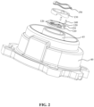
- FIG. 2 is a perspective view schematically showing a fixed scroll and a VVR valve of a compressor with a VVR function according to a first comparative example
- FIGS. 3A and 3B schematically show a fixed scroll and a VVR valve of a compressor with a VVR function according to a second comparative example.
- the compressor 1 includes a substantially closed housing 20.
- the housing 20 may be constituted by a substantially cylindrical body portion 22, a top cover 24 arranged at one end of the body portion 22, and a bottom cover 26 arranged at the other end of the body portion 22.
- a partition plate 30 is arranged between the top cover 24 and the body portion 22 to partition an internal space of the housing 20 into a fluid suction chamber 21 and a fluid discharge chamber 23.
- the fluid discharge chamber 23 is defined between the partition plate 30 and the top cover 24, and the fluid suction chamber 21 is defined among the partition plate 30, the body portion 22 and the bottom cover.
- a suction joint for sucking fluid is provided on the side of the fluid suction chamber 21, and a discharge joint for discharging the compressed fluid is provided on the side of the fluid discharge chamber 23.
- the compression mechanism sucks fluid from the fluid suction chamber 21 of the housing 20 and compresses the fluid and discharges the fluid into the fluid discharge chamber 23 of the housing 20. More specifically, Referring to FIG. 1 , for example, the compression mechanism may include a fixed scroll 40 and a movable scroll 50.
- the movable scroll 50 includes an end plate 54 and a spiral volute 56 formed on one side of the end plate.
- the fixed scroll 40 includes an end plate 44 and a spiral volute 46 formed on one side of the end plate.
- the end plate 44 includes an discharge port 42 formed at a substantially central position of the end plate, and a first variable volume ratio orifice 64 and a second variable volume ratio orifice 66 which are located radially outside the discharge port 42.
- the volute 46 of the fixed scroll 40 and volute 56 of movable scroll 50 mesh with each other to form a series of compression cavities with gradually decreasing volume and gradually increasing pressure from radially outer side to radially inner side.
- the radially outermost compression cavity has the smallest pressure
- the radially innermost compression cavity that is, the central compression cavity C1 at the center of the scroll
- multiple intermediate compression cavities located between the radially outermost position and the innermost position have an intermediate pressure between the largest pressure and the smallest pressure.
- the discharge port 42 is in fluid communication with the central compression cavity (the fluid communication described herein corresponds to direct fluid communication), and the first and second variable volume ratio orifices 64 and 66 are respectively in fluid communication with two intermediate compression cavities C2 and C3 located on opposite sides of the central compression cavity.
- a back pressure cavity 70 is provided on the side of the end plate 44 of the fixed scroll 40 opposite to the volute 46. More specifically, an inner annular wall 43 and an outer annular wall 45 are formed on the end plate 44. The inner annular wall 43 is formed around the discharge port 42. The back pressure cavity 70 is defined by an end plate 44, an inner annular wall 43 and an outer annular wall 45, and is closed by a sealing assembly provided therein.
- the back pressure cavity 70 is in fluid communication with one of the medium pressure cavities between the movable scroll 50 and the fixed scroll 40 through an axially extending through hole (not shown) formed in the end plate 44, thereby generating a force to press the fixed scroll 40 toward the movable scroll 50.
- the fixed scroll 40 and the movable scroll 50 can be effectively pressed together by the pressure in the back pressure cavity 70.
- a variable volume ratio valve 100 (hereinafter referred to as a VVR valve) is provided to prevent excessive compression of the working fluid.
- the VVR valve 100 includes a valve plate 110, a valve flap 120, a valve retainer 130, a pin 140 and a wave spring 150.
- the valve plate 110 is provided with a first fluid through hole and a second fluid through hole at positions corresponding to the first variable volume ratio orifice 64 and the second variable volume ratio orifice 66.
- the valve flap 120 is provided on the valve plate 110 to selectively open or close the fluid through holes.
- the valve flap 120 has two symmetrical movable parts 126 and one fixed part 124.
- the two movable parts 126 may be displaced relative to the fixed part 124 between an open position and a closed position.
- the valve retainer 130 is provided on the valve flap 120.
- the pin 140 extends through pin holes formed in the valve flap, the valve plate, and the valve retainer to circumferentially fix the valve plate 110, the valve flap 120, and the valve retainer 130.
- the wave spring 150 axially holds the valve flap, the valve plate and the valve retainer together.
- the working fluid is sucked into the compression mechanism and compressed as it flows from the radially outermost position to the radially innermost position, and the compressed fluid is discharged to the discharge area defined by the inner annular wall 43 through the discharge port 42, and then discharged to the discharge chamber 23 via a one-way valve provided at the central position of the partition plate 30.
- the fluid can be discharged to the discharge area through the VVR valve 100 in advance before reaching the radially innermost position.
- the pressure on the lower side of the valve flap 120 is greater than the pressure on the upper side, and the valve flap 120 moves toward the open position under the pressure difference, thereby allowing the fluid to be discharged in advance through the variable volume ratio orifices 64, 66 and the fluid through holes.
- the valve flap 120 returns to the closed position under the elastic restoring force and the pressure difference, thereby sealing the variable volume ratio orifices 64 and 66.
- the space inside the inner annular wall 43 is very limited.
- the space inside the inner annular wall 43 may only have a diameter of 20mm-30mm. In this case, it is difficult to fit the VVR valve 100 in the inside of the annular wall 43 to realize the compressor VVR function.
- FIGs. 3A and 3B schematically show a fixed scroll and a VVR valve of a compressor with a VVR function according to a second comparative example, with the other configuration of the compressor being basically the same as the corresponding configuration of the compressor according to the first comparative example.
- the compressor according to the second comparative example uses a cover plate 220 to separate the discharge area and the back pressure cavity respectively at the lower and upper parts, so that the installation space of the VVR valve is not limited by the size of the back pressure cavity as in the first comparative example.
- the fixed scroll end plate 144 and the cover plate 220 are fastened together by multiple screws 210.
- a groove 208 is provided on the side of the fixed scroll end plate 144 opposite to the volute, and is formed around the discharge port 202 and the variable volume ratio orifices 164 and 166, thereby forming an discharge area in the groove 208 (i.e., the lower side of the cover plate 220).
- a VVR valve 200 is arranged on each of variable volume ratio orifices 164 and 166.
- the VVR valve 200 allows fluid in the compression cavity to flow into the discharge area, and prevents fluid in the discharge area from flowing into the compression cavity.
- the VVR valve 200 may include a valve flap 220 covering the variable volume ratio orifice 164 or 166 and a valve stop 230 that prevents the valve flap 220 from being excessively deformed.
- the valve flap 220 has a movable part 226 and a fixed part 224, and the movable part 226 may be displaced relative to the fixed part 224 between an open position and a closed position.
- the VVR valve 200 may be fixed to the valve fixing hole formed in the fixed scroll end plate 144 by a fastener 240 such as a screw.
- a concave portion 222 is formed on the upper side of the cover plate 220, and is in fluid communication with the medium pressure cavity of the compression cavities through a medium pressure hole, and a sealing assembly may be provided in the concave portion 222 to form a back pressure cavity that provides an axial sealing force to the fixed scroll.
- a gasket 250 is provided between the cover plate 220 and the fixed scroll end plate 144.
- the inventor conceived an improved compressor structure, which can realize the VVR function not only with no limit of the installation space but also with a simple structure.
- the compressor according to the first embodiment of the present disclosure includes a fixed scroll 40A and a movable scroll 50A. Similar to the fixed scroll 40 and the movable scroll 50 according to the first comparative example, the volute 46 of the fixed scroll 40A and volute 56 of movable scroll 50A mesh with each other to form a series of compression cavities with gradually decreasing volume and gradually increasing pressure from radially outer side to radially inner side.
- the radially outermost compression cavity has the smallest pressure
- the radially innermost compression cavity that is, the central compression cavity at the center of the scroll has the largest pressure
- the multiple intermediate compression cavities located between the radially outermost position and the innermost position have an intermediate pressure between the largest pressure and the smallest pressure.
- the end plate 44A of the fixed scroll 40A is provided with a central discharge port 42 and a variable volume ratio orifice 64.
- the central discharge port 42 may be in fluid communication with the central compression cavity C1 of the compression cavities, and the variable volume ratio orifice 64 may be in fluid communication with the first intermediate compression cavity C2 located radially outside the central compression cavity (right side in FIG. 4 ).
- a second intermediate compression cavity C3 is formed on the opposite side of the central compression cavity (i.e., the left side in FIG. 4 ), and may be symmetrical to the first intermediate compression cavity C2 with respect to the central compression cavity C1.
- the intermediate compression cavities that have substantially the same pressure and cavity volume during the operation of the compressor are called a set of first intermediate compression cavity and second intermediate compression cavity.
- the fluid is discharged from the set of intermediate compression cavities at the same time, so as to avoid over-compression or under-compression of one of the compression cavities caused by discharging at different times and to reduce the loss of constant volume compression of the compressor.
- the compression cavities is symmetrical with respect to the central compression cavity, and the pressure and volume in the two symmetrical compression cavities are basically the same, which can be used as a set of intermediate compression cavities.
- two sets of (i.e., four) intermediate compression cavities with the approximately same pressure and volume may exist at the same time.
- the compression cavities formed by the fixed scroll and the movable scroll is asymmetric with respect to the central compression cavity. Therefore, the first intermediate compression cavity C2 and the second intermediate compression cavity C3 are also asymmetric.
- the technical idea of arranging the fluid channels described below according to the present disclosure is also applicable.
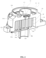
- the compressor according to the first embodiment of the present disclosure is provided with a fluid channel 300 between the first intermediate compression cavity C2 and the second intermediate compression cavity C3 to directly communicate the two compression cavities.
- the fluid channel 300 may be formed in the end plate 54A of the movable scroll 50A, and may include a first section 310, a second section 330, and a transverse connecting section 320.
- the first section 310 and the second section 330 may extend along the axial direction of the compressor and communicate with the first intermediate compression cavity C2 and the second intermediate compression cavity C3 respectively.
- the transverse connection section 320 may extend in a transverse direction perpendicular to the axial direction of the compressor and connect the first axial section 310 and the second axial section 330.
- the fluid in the second intermediate compression cavity C3 may flow to the first intermediate compression cavity C2 through the second axial section 330, the transverse connecting section 320 and the first axial section 310 in turn, and then may be discharged from the first intermediate compression cavity C2 to the discharge area defined by the annular wall 43 via the variable volume ratio orifice 64.
- the transverse connecting section 320 of the fluid channel 300 may be formed as a single section to reduce the clearance volume of the compressor.
- the first section 310 and the second section 330 are described herein to extend in the axial direction of the compressor, it should be understood that the first section 310 and the second section 330 may also extend in a slightly inclined direction.
- the first section 310 and the second section 330 extending axially are used to reduce the clearance volume of the compressor.
- a single VVR valve 200 may be provided on the variable volume ratio orifice 64.
- the VVR valve 200 may include a valve flap 220 covering the variable volume ratio orifice 64 and a valve stop 230 that prevents the valve flap 220 from being excessively deformed.
- the valve flap 220 may have a movable part 226 and a fixed part 224, and the movable part 226 may be displaced between an open position and a closed position relative to the fixed part 224.
- valve flap 220 closes the variable volume ratio orifice 64, while in the open position, the valve flap 220 opens the variable volume ratio orifice 64 and allows fluid to flow from the first intermediate compression cavity C2 to the discharge area defined by the annular wall 43.
- the VVR valve 200 may be fixed to a valve fixing hole formed in the end plate 44A of the fixed scroll 40A by a fastener such as a screw.
- the working fluid is sucked into the compression mechanism and compressed as it flows from the radially outermost position to the radially innermost position, and the compressed fluid is discharged to the discharge area defined by the inner annular wall 43 through the discharge port 42, and then discharged to the discharge chamber 23 through a one-way valve provided at the center of the partition plate 30.
- the fluid may be discharged to the discharge area in advance through the VVR valve 200 before reaching the radially innermost central compression cavity C1.
- the pressure at the lower side of the valve flap 220 is greater than the pressure at the upper side, and the movable part 226 of the valve flap 220 moves toward the open position under the pressure difference, thus allowing the fluid to be discharged from the intermediate compression cavities C2 and C3 to the discharge area in advance through the variable volume ratio orifice 64.
- valve flap 220 In case that the pressure of the fluid in the first intermediate compression cavity C2 and the second intermediate compression cavity C3 is less than the pressure of the fluid in the discharge chamber 23, the valve flap 220 returns to the closed position under the elastic restoring force and the pressure difference, thereby sealing the variable volume ratio orifice 64.
- the compressor according to the first embodiment of the present disclosure having a set of intermediate compression cavities C2, C3 is exemplarily showed, in which only a single variable volume ratio orifice 64 may be formed in the end plate 44A, and only a single valve flap with a single movable part may be needed to selectively open and close the variable volume ratio orifice 64. Therefore, compared with the compressor according to the first comparative example, the compressor according to the first embodiment of the present disclosure may have a greatly reduced installation space for the VVR valve, and may avoid the possibility that the VVR function cannot be realized due to limited space.
- the compressor according to the first embodiment of the present disclosure may avoid using additional cover plate 220, sealing gasket 250 and corresponding fasteners, reduce processing cost and component cost, and prevent fluid leakage which would otherwise occur in the high-pressure discharge area between the cover plate and the fixed scroll end plate.
- the VVR valve 200 which has a simple structure and has been conceived by the inventor, is adopted according to the first embodiment of the present disclosure, there is no need to develop additional new parts, so the development of the VVR function in the compressor is less difficult and fast.
- the compressor according to the first embodiment of the present disclosure has high structural compatibility and is applicable to most scrolls, and can be quickly improved to have the VVR function, e.g., by machining orifices on the un-improved scroll.
- a plug is provided in the transverse connecting section 320 to reduce the clearance volume.
- the transverse connecting section 320 must be drilled from the outer side of the end plate 54A (for example, the left side shown in FIG. 5 ) and extends to the point P1 intersecting the first axial section 310.
- the first part the remaining part from the origin of drilling on the left to the intersection point P2 (hereinafter referred to as the second part) is an invalid part caused by the machining process. Since there is residual discharged fluid in the transverse connecting section 320 after the VVR valve is closed, the ineffective second part may cause the clearance volume of the compressor to increase, thereby reducing the efficiency of the compressor.
- a plug may be provided in the transverse connecting section 320 to separate the first part and the second part, so as to reduce the clearance volume of the compressor.
- the plug 400 has a shape of short threaded stud, and a tool engaging groove 410 is formed on one end surface of the plug 400.
- An internal thread is formed over an entire length of the second part of the transverse connecting section 320, and a length of the plug 400 is smaller than a length of the second part.
- the tool engaging groove 410 on the plug 400 may be engaged with a tool such as a screwdriver, so that the plug 400 can be screwed into the second part and fixed at the position where the second part is adjacent to the first part, so as to separate the first part from the second part.
- the plug 500 is in the shape of an elongated step, and the transverse connecting section 320 is formed with internal threads only at the left end thereof.
- the plug 500 includes a first cylindrical portion 510 and a second cylindrical portion 520 with a diameter slightly smaller than the first cylindrical portion.
- the outer peripheral surface of the first cylindrical portion is formed with an external thread for engaging with the internal thread, and the second cylindrical portion may have a sufficient length filled in the second portion.
- FIGS. 9 and 10 there is provided a scroll mechanism of a compressor according to a second embodiment of the present disclosure.
- the fixed scroll 40B depicted in FIG.9 to FIG. 10 is used instead of the fixed scroll 40 according to the first comparative example, and other structures of the scroll compressor are basically unchanged.
- the end plate 44B of the fixed scroll 40B is provided with a fluid channel that directly communicates the first intermediate compression cavity with the second intermediate compression cavity.
- the fluid channel of the end plate 44B may include a first axial section 310, a second axial section 330, and a transverse connecting section 320B.
- the first axial section and the second axial section may extend along the axial direction of the compressor and communicate with the first intermediate compression cavity and the second intermediate compression cavity respectively, and the transverse connecting section 320B may extend in a transverse direction perpendicular to the axial direction of the compressor and connect the first axial section and the second axial section.
- the transverse connecting section 320B according to the second embodiment may be formed as a single section similarly to the transverse connecting section 320 according to the first embodiment.
- the transverse connecting section 320B may include a first transverse connecting section 322B and a second transverse connecting section 324B disposed on opposite sides of the discharge port 42 so that the transverse connecting section 320B bypasses the discharge port 42.
- the first transverse connecting section 322B and the second transverse connecting section 324B may intersect at the periphery portion P3 of the end plate 44B of the fixed scroll 40B, and a seal 326B may be provided at the intersection P3 to prevent fluid in the first intermediate compression cavity and the second intermediate compression cavity from being discharged through the periphery portion P3.
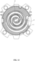
- a fluid channel 300C1 is provided in the volute 46C of the fixed scroll 40C, and includes a first slot 310C1, a second slot 330C1, and a connecting section (that is, corresponding to the trench according to the present disclosure) 320C1.
- the first slot 310C1 and the second slot 330C1 may respectively communicate with the first intermediate compression cavity C2 and the second intermediate compression cavity C3, and the transverse connecting section 320C1 may extend along the spiral volute 46C and connect the first slot 310 and the second slot 330.
- the volute 56C of the movable scroll 50C is provided with a fluid channel 300C2.
- the fluid channel 300C2 includes a first slot 310C2 and a second slot 330C2 that communicate with the first intermediate compression cavity C2 and the second intermediate compression cavity C3 respectively, and a connecting section (that is, corresponding to the trench according to the present disclosure) 320C2 extending along the spiral volute 56C and connecting the first slot 310C2 and the second slot 330C2.
- the fluid channels 300C1 and 300C2 are formed at the free ends of the volutes, thereby facilitating the processing of the fluid channels and reducing the influence on the strength of the volutes.
- the first intermediate compression cavity and the second intermediate compression cavity are communicated by both the fluid channel 300C1 formed in the volute 46C of the fixed scroll and the fluid channel 300C2 formed in the volute 56C of the movable scroll.
- the fluid communication between the first intermediate compression cavity and the second intermediate compression cavity can be realized by forming a fluid channel only on one of the volute 46C of the fixed scroll and the volute 56C of the movable scroll.
- the discharge port 42 is provided in the center of the end plate 44 of the fixed scroll 40, and in the case where the space defined by the inner annular wall 43 is very limited, this centrally arranged discharge port may interfere with the arrangement of the VVR valve.
- the VVR valve may at least partially extend over the central discharge port 42, so that the high-pressure fluid discharged through the central discharge port 42 may act on the valve flap of the VVR valve, causing the VVR valve to discharge the under-compressed fluid in advance when over-compression does not occur.
- the discharge port 42 includes a first discharge port portion 42A and a second discharge port portion 42B that communicate with each other.
- the first discharge port portion 42A is located in the center of the end plate 44 of the fixed scroll 40 and is in fluid communication with the central compression cavity C1
- the second discharge port portion 42B is offset from the first discharge port portion 42A in the radial direction and is in fluid communication with the discharge area defined by the inner annular wall 43.
- the second discharge port portion 42B located at the upper part of the axial direction is offset from the first discharge port portion 42A located at the center of the end plate at the lower part, thereby reducing the interference of the discharge port 42 to the VVR valve and providing a larger installation space for the VVR valve.
Landscapes
- Engineering & Computer Science (AREA)
- Mechanical Engineering (AREA)
- General Engineering & Computer Science (AREA)
- Physics & Mathematics (AREA)
- Fluid Mechanics (AREA)
- Rotary Pumps (AREA)
- Applications Or Details Of Rotary Compressors (AREA)
Claims (9)
- Spiralverdichter, umfassend:eine bewegliche Spirale (50A, 50C), die eine bewegliche Spiralendplatte (54A) und eine bewegliche Volute (56C) umfasst, die auf einer Seite der beweglichen Spiralendplatte gebildet ist, undeine feststehende Spirale (40A, 40B, 40C), die eine feststehende Spiralendplatte (44A, 44B) und eine feststehende Volute (46C) umfasst, die an einer Seite der feststehenden Spiralendplatte gebildet ist, wobei die feststehende Spirale und die bewegliche Spirale in Eingriff stehen, um eine Reihe von Kompressionshohlräumen dazwischen zu bilden, wobei die Reihe von Kompressionshohlräumen einen mittleren Kompressionshohlraum (C1) und Zwischenkompressionshohlräume umfassen, die radial außerhalb des mittleren Kompressionshohlraums angeordnet sind, wobei die Zwischenkompressionshohlräume mindestens einen Satz eines ersten Zwischenkompressionshohlraums (C2) und eines zweiten Zwischenkompressionshohlraums (C3) umfassen,wobei ein Fluidkanal (300, 300C1, 300C2) zwischen dem ersten Zwischenkompressionshohlraum und dem zweiten Zwischenkompressionshohlraum (C3) vorgesehen ist, um gezielt mit einem Auslassbereich zu kommunizieren, wobei der erste Zwischenkompressionshohlraum und der zweite Zwischenkompressionshohlraum direkt durch den Fluidkanal in Verbindung stehen,wobei der Spiralverdichter ferner Folgendes umfasst:
eine Hauptauslassöffnung (42) und eine Hilfsauslassöffnung (64), die in der feststehenden Spiralendplatte vorgesehen sind, wobei die Hauptauslassöffnung in Fluidverbindung mit dem mittleren Kompressionshohlraum (C1) steht und die Hilfsauslassöffnung von dem ersten Zwischenkompressionshohlraum und dem zweiten Zwischenkompressionshohlraum gemeinsam genutzt wird und gezielt mit dem Auslassbereich in Fluidverbindung steht. - Spiralverdichter nach Anspruch 1, wobei
der Fluidkanal einen ersten Abschnitt (310), der mit dem ersten Zwischenkompressionshohlraum kommuniziert, einen zweiten Abschnitt (330), der mit dem zweiten Zwischenkompressionshohlraum kommuniziert, und einen Verbindungsabschnitt (320, 320B), der den ersten Abschnitt und den zweiten Abschnitt verbindet, umfasst. - Spiralverdichter nach Anspruch 2, wobei
der Fluidkanal in der feststehenden Spiralendplatte (44B) angeordnet ist, der Verbindungsabschnitt einen ersten Verbindungsabschnitt (322B), der mit dem ersten Abschnitt kommuniziert, und einen zweiten Verbindungsabschnitt (324B), der mit dem zweiten Abschnitt kommuniziert, umfasst, wobei sich der erste Verbindungsabschnitt und der zweite Verbindungsabschnitt kreuzen, wobei die Hilfsauslassöffnung in direkter Fluidverbindung mit dem ersten Zwischenkompressionshohlraum oder dem zweiten Zwischenkompressionshohlraum steht. - Spiralverdichter nach Anspruch 2, wobei
der Fluidkanal in der beweglichen Spiralendplatte (54A) vorgesehen ist und der Verbindungsabschnitt (320) als ein einziger Abschnitt ausgebildet ist, wobei die Hilfsauslassöffnung in direkter Fluidverbindung mit dem ersten Zwischenkompressionshohlraum oder dem zweiten Zwischenkompressionshohlraum steht. - Spiralverdichter nach Anspruch 3 oder 4, wobei
der Verbindungsabschnitt ein erstes Ende hat, das in die feststehende Scrollendplatte oder die bewegliche Scrollendplatte eindringt, und am ersten Ende ein Stopfen vorgesehen ist, um ein Austreten von Fluiden zu verhindern. - Spiralverdichter nach Anspruch 1, wobei
der Fluidkanal (300C1, 300C2) an der feststehenden Volute (46C) und/oder der beweglichen Volute (56C) vorgesehen ist. - Spiralverdichter nach Anspruch 6, wobei
der Fluidkanal (300C1, 300C2) einen Graben umfasst, der an einer Endfläche eines freien Endes der feststehenden Volute und/oder der beweglichen Volute vorgesehen ist, sowie einen ersten Schlitz und einen zweiten Schlitz, die sich von dem Graben erstrecken und mit dem ersten Zwischenkompressionshohlraum (C2) bzw. dem zweiten Zwischenkompressionshohlraum (C3) kommunizieren. - Spiralverdichter nach Anspruch 1, wobei
eine innere ringförmige Wand (43) an der Seite der feststehenden Spiralendplatte (54A) gegenüber der feststehenden Volute (56A, 56B) gebildet ist, wobei die Hauptauslassöffnung und die Hilfsauslassöffnung radial innerhalb der inneren ringförmigen Wand angeordnet sind und der Auslassbereich durch die innere ringförmige Wand definiert ist, und ein Ventil (200) mit variablem Volumenverhältnis an der Hilfsauslassöffnung vorgesehen ist, wobei das Ventil mit variablem Volumenverhältnis gestattet, dass Fluid aus dem ersten Zwischenkompressionshohlraum (C2) und dem zweiten Zwischenkompressionshohlraum (C3) in den Auslassbereich fließt, und verhindert, dass Fluid in dem Auslassbereich in den ersten Zwischenkompressionshohlraum und den zweiten Zwischenkompressionshohlraum fließt. - Spiralverdichter nach Anspruch 8, wobei
das Ventil mit variablem Volumenverhältnis eine einzige Ventilklappe (220), die eine Öffnung mit variablem Volumenverhältnis abdeckt, und einen Ventilanschlag (230) umfasst, der den maximalen Bewegungsbereich der Ventilklappe steuert, wobei die Ventilklappe einen feststehenden Teil (224) und einen einzigen beweglichen Teil (226) umfasst, wobei der bewegliche Teil zwischen einer offenen Position und einer geschlossenen Position bezüglich des feststehenden Teils beweglich ist.
Applications Claiming Priority (3)
| Application Number | Priority Date | Filing Date | Title |
|---|---|---|---|
| CN201920765067.2U CN210218102U (zh) | 2019-05-24 | 2019-05-24 | 涡旋压缩机 |
| CN201910440249.7A CN111980918B (zh) | 2019-05-24 | 2019-05-24 | 涡旋压缩机 |
| PCT/CN2020/091986 WO2020238825A1 (zh) | 2019-05-24 | 2020-05-25 | 涡旋压缩机 |
Publications (3)
| Publication Number | Publication Date |
|---|---|
| EP3978754A1 EP3978754A1 (de) | 2022-04-06 |
| EP3978754A4 EP3978754A4 (de) | 2023-06-14 |
| EP3978754B1 true EP3978754B1 (de) | 2025-02-12 |
Family
ID=73553478
Family Applications (1)
| Application Number | Title | Priority Date | Filing Date |
|---|---|---|---|
| EP20812649.0A Active EP3978754B1 (de) | 2019-05-24 | 2020-05-25 | Spiralverdichter |
Country Status (3)
| Country | Link |
|---|---|
| US (1) | US12000392B2 (de) |
| EP (1) | EP3978754B1 (de) |
| WO (1) | WO2020238825A1 (de) |
Families Citing this family (1)
| Publication number | Priority date | Publication date | Assignee | Title |
|---|---|---|---|---|
| KR102619531B1 (ko) * | 2021-12-20 | 2023-12-29 | 엘지전자 주식회사 | 스크롤압축기 |
Family Cites Families (15)
| Publication number | Priority date | Publication date | Assignee | Title |
|---|---|---|---|---|
| JP2941489B2 (ja) * | 1991-06-17 | 1999-08-25 | 株式会社日立製作所 | スクロール圧縮機 |
| JPH07293456A (ja) | 1994-04-28 | 1995-11-07 | Sanyo Electric Co Ltd | スクロール圧縮機 |
| JPH11166490A (ja) * | 1997-12-03 | 1999-06-22 | Mitsubishi Electric Corp | 容量制御スクロール圧縮機 |
| US5996364A (en) * | 1998-07-13 | 1999-12-07 | Carrier Corporation | Scroll compressor with unloader valve between economizer and suction |
| KR100557056B1 (ko) | 2003-07-26 | 2006-03-03 | 엘지전자 주식회사 | 용량 조절식 스크롤 압축기 |
| US6883341B1 (en) * | 2003-11-10 | 2005-04-26 | Carrier Corporation | Compressor with unloader valve between economizer line and evaporator inlet |
| JP2007292030A (ja) * | 2006-04-27 | 2007-11-08 | Mitsubishi Heavy Ind Ltd | スクロール圧縮機 |
| US20080184733A1 (en) * | 2007-02-05 | 2008-08-07 | Tecumseh Products Company | Scroll compressor with refrigerant injection system |
| US8568118B2 (en) * | 2009-05-29 | 2013-10-29 | Emerson Climate Technologies, Inc. | Compressor having piston assembly |
| FR2960948B1 (fr) * | 2010-06-02 | 2015-08-14 | Danfoss Commercial Compressors | Compresseur frigorifique a spirales |
| CN103362802B (zh) * | 2012-03-29 | 2016-04-06 | 艾默生环境优化技术(苏州)有限公司 | 涡旋压缩机 |
| JP2014208985A (ja) * | 2013-04-16 | 2014-11-06 | 株式会社ケーヒン | スクロール型圧縮機 |
| JP6036797B2 (ja) * | 2014-12-12 | 2016-11-30 | ダイキン工業株式会社 | スクロール圧縮機 |
| CN204511881U (zh) * | 2015-03-16 | 2015-07-29 | 艾默生环境优化技术(苏州)有限公司 | 定涡旋部件及包括该定涡旋部件的涡旋压缩机 |
| CN210218102U (zh) * | 2019-05-24 | 2020-03-31 | 艾默生环境优化技术(苏州)有限公司 | 涡旋压缩机 |
-
2020
- 2020-05-25 WO PCT/CN2020/091986 patent/WO2020238825A1/zh not_active Ceased
- 2020-05-25 US US17/614,261 patent/US12000392B2/en active Active
- 2020-05-25 EP EP20812649.0A patent/EP3978754B1/de active Active
Also Published As
| Publication number | Publication date |
|---|---|
| WO2020238825A1 (zh) | 2020-12-03 |
| EP3978754A1 (de) | 2022-04-06 |
| EP3978754A4 (de) | 2023-06-14 |
| US12000392B2 (en) | 2024-06-04 |
| US20220243730A1 (en) | 2022-08-04 |
Similar Documents
| Publication | Publication Date | Title |
|---|---|---|
| CN113931842B (zh) | 涡旋压缩机构和涡旋压缩机 | |
| EP3334936B1 (de) | Verdichter | |
| CN211343341U (zh) | 涡旋压缩机 | |
| CN111980918B (zh) | 涡旋压缩机 | |
| EP3978754B1 (de) | Spiralverdichter | |
| WO2019045656A1 (en) | ROTARY COMPRESSOR | |
| CN210218102U (zh) | 涡旋压缩机 | |
| CN215333410U (zh) | 压缩机构 | |
| CN111472977B (zh) | 阀组件及压缩机 | |
| CN103362802B (zh) | 涡旋压缩机 | |
| CN217999879U (zh) | 压缩机构及涡旋压缩机 | |
| KR20240090204A (ko) | 압축기 | |
| CN113494451A (zh) | 压缩机构及涡旋压缩机 | |
| US6390792B1 (en) | Venting passage for isolation block of scroll compressor and check valve for the same | |
| US10941774B2 (en) | Variable-capacity mechanism of scroll compressor and scroll compressor | |
| JP6421747B2 (ja) | 圧縮機 | |
| CN119860347A (zh) | 压缩机构 | |
| JP2001027188A (ja) | スクロール流体機械 | |
| CN115143103B (zh) | 压缩机构 | |
| US12146490B2 (en) | Compression mechanism and scroll compressor | |
| CN220378486U (zh) | 涡旋压缩机 | |
| CN218376868U (zh) | 定涡旋组件和涡旋压缩机 | |
| US5004408A (en) | Discharge system for rotary rolling piston compressor | |
| WO2024002338A1 (zh) | 定涡旋组件、涡旋压缩机及加工定涡旋组件的方法 | |
| CN223270172U (zh) | 涡旋压缩机 |
Legal Events
| Date | Code | Title | Description |
|---|---|---|---|
| STAA | Information on the status of an ep patent application or granted ep patent |
Free format text: STATUS: THE INTERNATIONAL PUBLICATION HAS BEEN MADE |
|
| PUAI | Public reference made under article 153(3) epc to a published international application that has entered the european phase |
Free format text: ORIGINAL CODE: 0009012 |
|
| STAA | Information on the status of an ep patent application or granted ep patent |
Free format text: STATUS: REQUEST FOR EXAMINATION WAS MADE |
|
| 17P | Request for examination filed |
Effective date: 20211123 |
|
| AK | Designated contracting states |
Kind code of ref document: A1 Designated state(s): AL AT BE BG CH CY CZ DE DK EE ES FI FR GB GR HR HU IE IS IT LI LT LU LV MC MK MT NL NO PL PT RO RS SE SI SK SM TR |
|
| DAV | Request for validation of the european patent (deleted) | ||
| DAX | Request for extension of the european patent (deleted) | ||
| A4 | Supplementary search report drawn up and despatched |
Effective date: 20230516 |
|
| RIC1 | Information provided on ipc code assigned before grant |
Ipc: F04C 28/24 20060101ALI20230510BHEP Ipc: F04C 29/12 20060101ALI20230510BHEP Ipc: F04C 29/00 20060101ALI20230510BHEP Ipc: F04C 28/10 20060101ALI20230510BHEP Ipc: F04C 18/02 20060101AFI20230510BHEP |
|
| RAP3 | Party data changed (applicant data changed or rights of an application transferred) |
Owner name: COPELAND CLIMATE TECHNOLOGIES (SUZHOU) CO., LTD. |
|
| GRAP | Despatch of communication of intention to grant a patent |
Free format text: ORIGINAL CODE: EPIDOSNIGR1 |
|
| STAA | Information on the status of an ep patent application or granted ep patent |
Free format text: STATUS: GRANT OF PATENT IS INTENDED |
|
| RIC1 | Information provided on ipc code assigned before grant |
Ipc: F04C 28/24 20060101ALI20240808BHEP Ipc: F04C 29/12 20060101ALI20240808BHEP Ipc: F04C 29/00 20060101ALI20240808BHEP Ipc: F04C 28/10 20060101ALI20240808BHEP Ipc: F04C 18/02 20060101AFI20240808BHEP |
|
| INTG | Intention to grant announced |
Effective date: 20240910 |
|
| GRAS | Grant fee paid |
Free format text: ORIGINAL CODE: EPIDOSNIGR3 |
|
| GRAA | (expected) grant |
Free format text: ORIGINAL CODE: 0009210 |
|
| STAA | Information on the status of an ep patent application or granted ep patent |
Free format text: STATUS: THE PATENT HAS BEEN GRANTED |
|
| AK | Designated contracting states |
Kind code of ref document: B1 Designated state(s): AL AT BE BG CH CY CZ DE DK EE ES FI FR GB GR HR HU IE IS IT LI LT LU LV MC MK MT NL NO PL PT RO RS SE SI SK SM TR |
|
| P01 | Opt-out of the competence of the unified patent court (upc) registered |
Free format text: CASE NUMBER: APP_242/2025 Effective date: 20250103 |
|
| REG | Reference to a national code |
Ref country code: GB Ref legal event code: FG4D |
|
| REG | Reference to a national code |
Ref country code: CH Ref legal event code: EP |
|
| REG | Reference to a national code |
Ref country code: DE Ref legal event code: R096 Ref document number: 602020046015 Country of ref document: DE |
|
| REG | Reference to a national code |
Ref country code: IE Ref legal event code: FG4D |
|
| REG | Reference to a national code |
Ref country code: NL Ref legal event code: MP Effective date: 20250212 |
|
| PG25 | Lapsed in a contracting state [announced via postgrant information from national office to epo] |
Ref country code: RS Free format text: LAPSE BECAUSE OF FAILURE TO SUBMIT A TRANSLATION OF THE DESCRIPTION OR TO PAY THE FEE WITHIN THE PRESCRIBED TIME-LIMIT Effective date: 20250512 |
|
| PG25 | Lapsed in a contracting state [announced via postgrant information from national office to epo] |
Ref country code: FI Free format text: LAPSE BECAUSE OF FAILURE TO SUBMIT A TRANSLATION OF THE DESCRIPTION OR TO PAY THE FEE WITHIN THE PRESCRIBED TIME-LIMIT Effective date: 20250212 |
|
| PG25 | Lapsed in a contracting state [announced via postgrant information from national office to epo] |
Ref country code: PL Free format text: LAPSE BECAUSE OF FAILURE TO SUBMIT A TRANSLATION OF THE DESCRIPTION OR TO PAY THE FEE WITHIN THE PRESCRIBED TIME-LIMIT Effective date: 20250212 |
|
| PGFP | Annual fee paid to national office [announced via postgrant information from national office to epo] |
Ref country code: DE Payment date: 20250423 Year of fee payment: 6 |
|
| PG25 | Lapsed in a contracting state [announced via postgrant information from national office to epo] |
Ref country code: ES Free format text: LAPSE BECAUSE OF FAILURE TO SUBMIT A TRANSLATION OF THE DESCRIPTION OR TO PAY THE FEE WITHIN THE PRESCRIBED TIME-LIMIT Effective date: 20250212 |
|
| REG | Reference to a national code |
Ref country code: LT Ref legal event code: MG9D |
|
| PG25 | Lapsed in a contracting state [announced via postgrant information from national office to epo] |
Ref country code: IS Free format text: LAPSE BECAUSE OF FAILURE TO SUBMIT A TRANSLATION OF THE DESCRIPTION OR TO PAY THE FEE WITHIN THE PRESCRIBED TIME-LIMIT Effective date: 20250612 Ref country code: NO Free format text: LAPSE BECAUSE OF FAILURE TO SUBMIT A TRANSLATION OF THE DESCRIPTION OR TO PAY THE FEE WITHIN THE PRESCRIBED TIME-LIMIT Effective date: 20250512 |
|
| PG25 | Lapsed in a contracting state [announced via postgrant information from national office to epo] |
Ref country code: NL Free format text: LAPSE BECAUSE OF FAILURE TO SUBMIT A TRANSLATION OF THE DESCRIPTION OR TO PAY THE FEE WITHIN THE PRESCRIBED TIME-LIMIT Effective date: 20250212 |
|
| PG25 | Lapsed in a contracting state [announced via postgrant information from national office to epo] |
Ref country code: HR Free format text: LAPSE BECAUSE OF FAILURE TO SUBMIT A TRANSLATION OF THE DESCRIPTION OR TO PAY THE FEE WITHIN THE PRESCRIBED TIME-LIMIT Effective date: 20250212 |
|
| PG25 | Lapsed in a contracting state [announced via postgrant information from national office to epo] |
Ref country code: PT Free format text: LAPSE BECAUSE OF FAILURE TO SUBMIT A TRANSLATION OF THE DESCRIPTION OR TO PAY THE FEE WITHIN THE PRESCRIBED TIME-LIMIT Effective date: 20250612 Ref country code: LV Free format text: LAPSE BECAUSE OF FAILURE TO SUBMIT A TRANSLATION OF THE DESCRIPTION OR TO PAY THE FEE WITHIN THE PRESCRIBED TIME-LIMIT Effective date: 20250212 |
|
| PGFP | Annual fee paid to national office [announced via postgrant information from national office to epo] |
Ref country code: FR Payment date: 20250423 Year of fee payment: 6 |
|
| PG25 | Lapsed in a contracting state [announced via postgrant information from national office to epo] |
Ref country code: GR Free format text: LAPSE BECAUSE OF FAILURE TO SUBMIT A TRANSLATION OF THE DESCRIPTION OR TO PAY THE FEE WITHIN THE PRESCRIBED TIME-LIMIT Effective date: 20250513 Ref country code: BG Free format text: LAPSE BECAUSE OF FAILURE TO SUBMIT A TRANSLATION OF THE DESCRIPTION OR TO PAY THE FEE WITHIN THE PRESCRIBED TIME-LIMIT Effective date: 20250212 |
|
| REG | Reference to a national code |
Ref country code: AT Ref legal event code: MK05 Ref document number: 1766257 Country of ref document: AT Kind code of ref document: T Effective date: 20250212 |
|
| PG25 | Lapsed in a contracting state [announced via postgrant information from national office to epo] |
Ref country code: SE Free format text: LAPSE BECAUSE OF FAILURE TO SUBMIT A TRANSLATION OF THE DESCRIPTION OR TO PAY THE FEE WITHIN THE PRESCRIBED TIME-LIMIT Effective date: 20250212 |
|
| PG25 | Lapsed in a contracting state [announced via postgrant information from national office to epo] |
Ref country code: SM Free format text: LAPSE BECAUSE OF FAILURE TO SUBMIT A TRANSLATION OF THE DESCRIPTION OR TO PAY THE FEE WITHIN THE PRESCRIBED TIME-LIMIT Effective date: 20250212 |
|
| PG25 | Lapsed in a contracting state [announced via postgrant information from national office to epo] |
Ref country code: DK Free format text: LAPSE BECAUSE OF FAILURE TO SUBMIT A TRANSLATION OF THE DESCRIPTION OR TO PAY THE FEE WITHIN THE PRESCRIBED TIME-LIMIT Effective date: 20250212 |
|
| PG25 | Lapsed in a contracting state [announced via postgrant information from national office to epo] |
Ref country code: IT Free format text: LAPSE BECAUSE OF FAILURE TO SUBMIT A TRANSLATION OF THE DESCRIPTION OR TO PAY THE FEE WITHIN THE PRESCRIBED TIME-LIMIT Effective date: 20250212 |
|
| PG25 | Lapsed in a contracting state [announced via postgrant information from national office to epo] |
Ref country code: AT Free format text: LAPSE BECAUSE OF FAILURE TO SUBMIT A TRANSLATION OF THE DESCRIPTION OR TO PAY THE FEE WITHIN THE PRESCRIBED TIME-LIMIT Effective date: 20250212 |
|
| PG25 | Lapsed in a contracting state [announced via postgrant information from national office to epo] |
Ref country code: EE Free format text: LAPSE BECAUSE OF FAILURE TO SUBMIT A TRANSLATION OF THE DESCRIPTION OR TO PAY THE FEE WITHIN THE PRESCRIBED TIME-LIMIT Effective date: 20250212 Ref country code: CZ Free format text: LAPSE BECAUSE OF FAILURE TO SUBMIT A TRANSLATION OF THE DESCRIPTION OR TO PAY THE FEE WITHIN THE PRESCRIBED TIME-LIMIT Effective date: 20250212 |
|
| PG25 | Lapsed in a contracting state [announced via postgrant information from national office to epo] |
Ref country code: RO Free format text: LAPSE BECAUSE OF FAILURE TO SUBMIT A TRANSLATION OF THE DESCRIPTION OR TO PAY THE FEE WITHIN THE PRESCRIBED TIME-LIMIT Effective date: 20250212 |
|
| PG25 | Lapsed in a contracting state [announced via postgrant information from national office to epo] |
Ref country code: SK Free format text: LAPSE BECAUSE OF FAILURE TO SUBMIT A TRANSLATION OF THE DESCRIPTION OR TO PAY THE FEE WITHIN THE PRESCRIBED TIME-LIMIT Effective date: 20250212 |
|
| REG | Reference to a national code |
Ref country code: DE Ref legal event code: R097 Ref document number: 602020046015 Country of ref document: DE |
|
| PLBE | No opposition filed within time limit |
Free format text: ORIGINAL CODE: 0009261 |
|
| STAA | Information on the status of an ep patent application or granted ep patent |
Free format text: STATUS: NO OPPOSITION FILED WITHIN TIME LIMIT |
|
| REG | Reference to a national code |
Ref country code: CH Ref legal event code: H13 Free format text: ST27 STATUS EVENT CODE: U-0-0-H10-H13 (AS PROVIDED BY THE NATIONAL OFFICE) Effective date: 20251223 |
|
| REG | Reference to a national code |
Ref country code: CH Ref legal event code: L10 Free format text: ST27 STATUS EVENT CODE: U-0-0-L10-L00 (AS PROVIDED BY THE NATIONAL OFFICE) Effective date: 20251224 |
|
| PG25 | Lapsed in a contracting state [announced via postgrant information from national office to epo] |
Ref country code: LU Free format text: LAPSE BECAUSE OF NON-PAYMENT OF DUE FEES Effective date: 20250525 |
|
| PG25 | Lapsed in a contracting state [announced via postgrant information from national office to epo] |
Ref country code: CH Free format text: LAPSE BECAUSE OF NON-PAYMENT OF DUE FEES Effective date: 20250531 |
|
| 26N | No opposition filed |
Effective date: 20251113 |
|
| GBPC | Gb: european patent ceased through non-payment of renewal fee |
Effective date: 20250525 |
|
| PG25 | Lapsed in a contracting state [announced via postgrant information from national office to epo] |
Ref country code: MC Free format text: LAPSE BECAUSE OF FAILURE TO SUBMIT A TRANSLATION OF THE DESCRIPTION OR TO PAY THE FEE WITHIN THE PRESCRIBED TIME-LIMIT Effective date: 20250212 |