EP3978699B1 - Demontierbare trennwandsystem - Google Patents
Demontierbare trennwandsystem Download PDFInfo
- Publication number
- EP3978699B1 EP3978699B1 EP20200055.0A EP20200055A EP3978699B1 EP 3978699 B1 EP3978699 B1 EP 3978699B1 EP 20200055 A EP20200055 A EP 20200055A EP 3978699 B1 EP3978699 B1 EP 3978699B1
- Authority
- EP
- European Patent Office
- Prior art keywords
- demountable
- panel
- board
- partition
- panel mount
- Prior art date
- Legal status (The legal status is an assumption and is not a legal conclusion. Google has not performed a legal analysis and makes no representation as to the accuracy of the status listed.)
- Active
Links
Images


Classifications
-
- E—FIXED CONSTRUCTIONS
- E04—BUILDING
- E04B—GENERAL BUILDING CONSTRUCTIONS; WALLS, e.g. PARTITIONS; ROOFS; FLOORS; CEILINGS; INSULATION OR OTHER PROTECTION OF BUILDINGS
- E04B2/00—Walls, e.g. partitions, for buildings; Wall construction with regard to insulation; Connections specially adapted to walls
- E04B2/74—Removable non-load-bearing partitions; Partitions with a free upper edge
- E04B2/7401—Removable non-load-bearing partitions; Partitions with a free upper edge assembled using panels without a frame or supporting posts, with or without upper or lower edge locating rails
-
- E—FIXED CONSTRUCTIONS
- E04—BUILDING
- E04B—GENERAL BUILDING CONSTRUCTIONS; WALLS, e.g. PARTITIONS; ROOFS; FLOORS; CEILINGS; INSULATION OR OTHER PROTECTION OF BUILDINGS
- E04B2/00—Walls, e.g. partitions, for buildings; Wall construction with regard to insulation; Connections specially adapted to walls
- E04B2/74—Removable non-load-bearing partitions; Partitions with a free upper edge
- E04B2/7407—Removable non-load-bearing partitions; Partitions with a free upper edge assembled using frames with infill panels or coverings only; made-up of panels and a support structure incorporating posts
-
- E—FIXED CONSTRUCTIONS
- E04—BUILDING
- E04B—GENERAL BUILDING CONSTRUCTIONS; WALLS, e.g. PARTITIONS; ROOFS; FLOORS; CEILINGS; INSULATION OR OTHER PROTECTION OF BUILDINGS
- E04B2/00—Walls, e.g. partitions, for buildings; Wall construction with regard to insulation; Connections specially adapted to walls
- E04B2/74—Removable non-load-bearing partitions; Partitions with a free upper edge
- E04B2/7401—Removable non-load-bearing partitions; Partitions with a free upper edge assembled using panels without a frame or supporting posts, with or without upper or lower edge locating rails
- E04B2/7403—Removable non-load-bearing partitions; Partitions with a free upper edge assembled using panels without a frame or supporting posts, with or without upper or lower edge locating rails with special measures for sound or thermal insulation including fire protection
-
- E—FIXED CONSTRUCTIONS
- E04—BUILDING
- E04B—GENERAL BUILDING CONSTRUCTIONS; WALLS, e.g. PARTITIONS; ROOFS; FLOORS; CEILINGS; INSULATION OR OTHER PROTECTION OF BUILDINGS
- E04B2/00—Walls, e.g. partitions, for buildings; Wall construction with regard to insulation; Connections specially adapted to walls
- E04B2/74—Removable non-load-bearing partitions; Partitions with a free upper edge
- E04B2002/7461—Details of connection of sheet panels to frame or posts
- E04B2002/7462—Details of connection of sheet panels to frame or posts using resilient connectors, e.g. clips
- E04B2002/7464—Details of connection of sheet panels to frame or posts using resilient connectors, e.g. clips clasping a flange of a profile
-
- E—FIXED CONSTRUCTIONS
- E04—BUILDING
- E04B—GENERAL BUILDING CONSTRUCTIONS; WALLS, e.g. PARTITIONS; ROOFS; FLOORS; CEILINGS; INSULATION OR OTHER PROTECTION OF BUILDINGS
- E04B2/00—Walls, e.g. partitions, for buildings; Wall construction with regard to insulation; Connections specially adapted to walls
- E04B2/74—Removable non-load-bearing partitions; Partitions with a free upper edge
- E04B2002/7461—Details of connection of sheet panels to frame or posts
- E04B2002/7466—Details of connection of sheet panels to frame or posts using hooks
Definitions
- the invention relates to a demountable wall partition system. More specifically, the invention relates to a demountable wall partition system based on a board and a panel mount bracket attached thereto.
- office spaces can be built by using pre-fabricated partition wall systems or by using removeable partition systems (such as free-standing room dividers). These ways of building office spaces require skill and takes a considerable time to build or have less beneficial acoustic, fire and/or thermal insulation properties. Further, when the office space needs to be altered or is removed, the walls are constructed and built in such a way that the wall is at least partly destroyed when taken down and can therefore not easily be reused.
- the object of the present invention is to at least partly overcome one or more of the above-identified limitations of the prior art.
- it is an object to provide a demountable and reusable wall partition system.
- a demountable wall partition system comprising a first and second demountable partition panel having a front surface, a rear surface and side edges connecting the front surface and the rear surface, the demountable partition panel comprising a board having a rear surface forming to the rear surface of the demountable partition panel, at least one panel mount bracket connected to the board and protruding from the rear surface, wherein the at least one panel mount bracket comprises a first end flange extending in a first flange plane parallel with the rear surface of the board, and a second end flange.
- the first and second demountable partition panels are arranged spaced apart with the rear sides facing each other such that the at least one panel mount bracket of the respective first and second demountable partition panel form at least one pair of aligned panel mount brackets, wherein the at least one pair of aligned panel mount brackets are connected to each other by means of the flange connection element which is connected to the second end flanges of the at least one pair of aligned panel mount brackets such that the flange connection element is supported by the at least one pair of aligned panel mount brackets.
- the board of at least one of the first and second demountable partition panel is a gypsum board and more preferably a reinforced gypsum board.
- a demountable wall partition system in which a partition panel may easily be demounted with maintained integrity and thus also reused.
- the partition panel is provided with at least one panel mount bracket protruding from the rear surface of the board and connectable to the panel mount bracket of an opposing partition element.
- the partition panel may easily be used for erecting a partition wall and may subsequently, if need arises, be demounted from the partition wall and reused.
- the second end flange is connected to the second end flange of the panel mount bracket of the opposing demountable partition panel by means of a flange connection element.
- the partition panel may be reliable connected to, and subsequently if necessary disconnected from an opposing partition panel.
- the first end flange of the panel mount bracket may be attached to the rear surface of the board.
- the use of a board thus facilitates secure attachment of the panel mount bracket to the rear surface of the board, for instance by means of screws.
- the end flange may be embedded in the board or, in case the partition panel comprises several boards, sandwiched between two boards.
- the demountable partition panel may comprise an edge cover at least partly covering the side edges.
- the provision of the edge cover may protect the side edges of the demountable partition panel during handling and transportation.
- the edge cover may be configured to form a frame structure, thereby providing additional rigidity to the partition panel.
- the edge cover may comprise an L-shaped profile extending along one of the side edges.
- the L-shaped profile may comprise a flange extending in parallel with the one side edge and having a width which is smaller than a thickness of the demountable partition panel.
- the L-shaped profile may be arranged with one flange extending in parallel with and attached to the rear surface of the board, while the other flange extends in parallel with the side edge providing protection thereto without being visible from the front surface of the demountable partition panel.
- the demountable partition panel may comprise an additional board facing a front surface of the board.
- the demountable partition panel may have sandwiched structure improving acoustical properties of the demountable partition panel.
- the additional board may be glued to the board.
- the demountable partition panel may comprise a gasket arranged on the panel mount bracket and configured for engagement with the panel mount bracket of an opposing demountable partition panel.
- the provision of a gasket may reduce transmission of sound through a partition wall comprising the demountable partition panel.
- the second end flange of the at least one panel mount bracket may extend in a direction having a component being perpendicular to the rear surface of the board. Further, the second end flange may extend from a first position towards a second position, corresponding to a free end of the second end flange, the second position being spaced apart from the rear surface of the board, wherein a distance between the rear surface and the second position is greater than a distance between the rear surface and the first position.
- the at least one panel mount bracket of the partition panel may be connected to an aligned panel mount bracket of an opposing partition panel by means of a flange connection element gripping over the respective free end of the second end flanges thereby securing the relative position of the two partition panels in both lateral and vertical direction.
- the demountable partition panel may comprise a plurality of panel mount brackets distributed on the rear surface in a spaced apart manner.
- the flange connection element may be an elongated profile configured to receive the second end flanges of the pair of aligned mount brackets.
- the flange connection element may be shaped as a slide profile configured to be slid over the second end flanges for connecting the pair of aligned panel mound brackets to each other.
- the elongated profile may have a c-shaped cross section.
- a gasket may be arranged between the pair of aligned panel mount brackets. Herby, transmission of sound trough the wall partition system may be reduced.
- the demountable wall partition system may further comprise an insulating material arranged in a void formed between the first and second demountable partition panels.
- the provision of insulating material in the void may improve the acoustical properties of the wall partition system.
- a method for installing a demountable wall partition system comprises arranging a first and second demountable partition panel as described above such that the panel mount bracket of the first demountable partition panel opposes the panel mount bracket of the second demountable partition panel thereby forming at least one pair of aligned panel mount brackets and connecting the flange connection element to the second end flanges of the at least one pair of aligned panel mount brackets such that the flange connection element is supported by the at least one pair of aligned panel mount brackets.
- a reinforced gypsum board is to be understood as a gypsum board or plasterboard that can be reinforced with a backing lamina or without a backing lamina.
- the reinforced gypsum board may comprise more than 50 wt% gypsum and, relative to the gypsum, at least 1 wt% fibres (e.g. glass fibres) embedded in the set gypsum core and at least 1 wt% polymeric additive.
- the polymeric additive may comprise starch or synthetic polymers such as polyvinyl acetate.
- the board may comprise multiple different types of polymeric additive.
- the reinforced gypsum board may also comprise between 45 and 85 %-by-weight calcium sulphate dihydrate, between 5 and 15 %-by-weight of paper fibres.
- the reinforced gypsum board may be a gypsum fibre board.
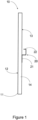
- Fig. 1 illustrates a demountable partition panel 10.
- the demountable partition panel 10 has a front surface 12, a rear surface 13 and side edges 14 that connect the front 12 and rear surface 13.
- the demountable partition panel 10 comprises a board 11 and in the shown embodiment it is thus the board 11 that forms the front surface 12, the rear surface 13 and the side edges 14 connecting the front 12 and rear surface 13 of the panel 10.
- the demountable partition panel 10 also comprises at least one panel mount bracket 20 connected to the board 11 and configured for connection to a panel mount bracket 20 of an opposing demountable partition panel 10.
- connection may be made by means of a flange connection element 15.
- the at least one panel mount bracket 20 comprises a first end flange 21 extending in a first flange plane parallel with and attached to the rear surface 13 of the board 11.
- the at least one panel mount bracket 20 further comprises a second end flange 22 configured to be connected to a second end flange of a panel mount bracket of an opposing demountable partition panel, and in the shown embodiment, the second end flange is configured to be connected to the second end flange of the opposing demountable partition panel by means of the flange connection element 15.
- demountable wall partition panel 10 By having the panel mount bracket 20 attached to the board 11 a simple, durable and stable demountable wall partition panel 10 is provided. This allows for easier installation, demounting and reusability of the demountable wall partition panel 10.
- the demountable wall partition panel 10 reduces time, waste and any on-site preparations for constructing temporary walls for offices or rooms.
- the board 11 can ba any type of board 11 that allows for the attachment of the panel mount bracket 20 to the board 11 by for example gluing or screwing.
- the board 11 could in some examples be a board 11 that has an average screw pull-out strength of more than 500 N.
- the board 11 may for example be a reinforced gypsum board 11 or a reinforced gypsum board 11 having an average screw pull-out strength of more than 500 N. It would normally not be possible to attach the panel mount bracket 20 to a standard gypsum board by screwing the panel mount bracket 20 to the standard gypsum board due to the friability of standard gypsum boards.
- the demountable partition panel 10 may have a width between 500-1000 mm, or more preferably between 600-900 mm, such as a standard board width. Additionally, since the panel mount bracket 20 is attached to the rear surface 13 of the board 11, the front surface 12 is untouched and can be customized according to any need.
- the panel mount bracket 20 can be made of metal such as galvanized steel and/or aluminium, composite materials and/or of plastic.
- the panel mount bracket 20 can be pre-attached to the board 11 when for example producing the demountable partition wall panel 10 in a production line.
- the panel mount bracket 20 can also be attached when building the wall for the office or room.
- the attachment of the panel mount bracket 20 to the board 11 can be by use of glue, screws, nails, tape or any other suitable attachment method.
- the panel mount bracket 20 may also be integrated into the the slurry when forming the board 11.
- the panel mount bracket 20 may also be embedded between for example two boards 11 by having the first flange 21 arranged between the two boards 11 and the second flange 22 sticking out on the back side of one of the boards 11.
- the demountable partition panel 10 may comprise a plurality of panel mount brackets 20 distributed on the rear surface 13 in a spaced apart manner.
- the panel mount brackets 20 may be arranged in such a way that gives most stability to a wall system 100 comprising two or more demountable partition panels 10.
- the panel mount brackets 20 may also be arranged in such a way to accommodate placement of technical components such as switches, sockets and/or steering.
- the panel mount brackets 20 may also be arranged in such a way to accommodate wiring or other components that should run behind the demountable partition panel 10.
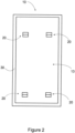
- the demountable partition panel 10 may have an edge cover 30, also illustrated in Fig. 2 .
- the edge cover 30 covers at least partly the side edges 14. By at least partly covering the side edges 14 of the partition panel 10, the partition panel 10 is protected from accidently being damaged during storing, handling or transportation.
- the edge cover 30 may also only cover some of the side edges 14, such as a bottom and top side edges 14.
- the edge cover 30 is in some example made up by several edge cover elements or the edge cover 30 can be made up by one coherent edge cover element.
- the edge cover 30 may also form a frame structure.
- the edge cover 30 may form the frame structure as fitted separate edge cover elements 30 or as a single frame element edge cover 30. The frame structure improves stability and/or durability of the demountable partition panel 10.
- the edge cover 30 may have a length between 500-2500 mm or any length for fitting around the partition panel 10 or at least parts of the partition panel 10.
- the edge cover 30 may also be long enough to cover a plurality of partition panel 10.
- the edge cover 30 may be made to cover a side edge 14 facing a floor and the edge cover 30 may then adapted in length to cover two partition panel 10 placed next to each other.
- the edge cover 30 comprises in some examples an L-shaped profile extending along at least one of the side edges 14.
- the L-shaped profile comprises one flange 31 extending parallel to one side edge 14 and has a width CW smaller than a thickness BT of the partition panel 10.
- the front surface 12 is free from any edge cover 30 and thus clean and ready to be customized as desired. Also, the edge cover 30 will be less visible.
- the other flange of the L-shaped profile may be attached to the rear surface 13 by glue and/or screw.
- the width CW and/or height of the L-shaped profile may be between 10-50 mm, more preferably between 20-25mm.
- the L-profile may also comprise pre-drilled holes for easier attachment by screws to the board 11.
- the edge cover 30 may also completely cover the side edges 14 and thus being visible and contacting both the front and rear surface 12, 13.
- the demountable partition panel 10 comprises in some examples an additional board 110 facing the front surface 12 of the board 11, illustrated in Fig. 4 .
- the demountable partition panel may thus be provided with a sandwich structure.
- the additional board 110 may be adapted for better sound proofing or have better resistance against fire and/or moisture or other desired structural features.
- the additional board 110 may also improve the structural strength and/or durability of the demountable partition panel 10.
- the additional board 110 my be a board and/or a standard board.
- the demountable partition panel 10 may comprise more elements and/or boards than the board 11 and the additional board 110.
- the board 11 and the additional board 110 are glued together.
- the board 11 and the additional board 110 may be glued together in a uniform or a non-uniform application of the glue.
- Other examples of connecting the board 11 and the additional board 110 together may be by using tape.
- the board 11 and the additional board 110 my also be hold together by the the edge cover 30 completely covering the side edges 14 and thus being visible and contacting both a front surface of for example the additional board 110 and the rear surface of the board 11.
- the board 11 and the additional board 110 may also be glued to the edge cover 30.
- the board 11 and the additional board 110 may also be glued to the edge cover 30 and between the board 11 and the additional board 110.
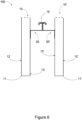
- the demountable partition panel 10 comprises a gasket 16 arranged on the panel mount bracket 20 and configured to abut the panel mount bracket of an opposing demountable partition panel.
- the gasket 16 acts as a sound isolating member between the two panel mount brackets and their respective demountable partition panels.
- the second end flange 22 of the at least one panel mount bracket 20 extends in a direction having a component being perpendicular to the rear surface 13 of the board 11, illustrated in e.g. Figs. 5A-5D .
- the panel mount bracket 20 is formed such that the flange connection element connects and secures together two panel mount brackets 20 and their respective partition panel 10.
- the panel mount bracket 20 may also be shaped as illustrated in Fig. 5B and the difference from for example 5A is that that the second end flange 22 also extends parallel to the rear surface 13 as for the first end flange 21.
- the flange connection element 15 in 5B may thus simply be clamped or fitted to secure two panel mount brackets 20 together.
- the second end flange 22 may extend in the direction perpendicular to the rear surface 13 from a first position towards a second position corresponding to a free end of the second end flange 22, wherein the second position is spaced apart from the rear surface 13 but still closer to the rear surface 13 than the first position as illustrated in e.g. Figs. 5A and 5C .
- Such a configuration of the second end flange 22 enables connection of a pair of aliged panel mount brackets 20 by means of the flange connection element 15 gripping over the free ends of the second end flanges 22, thereby securing the connection of the pair of aliged panel mount brackets 20 in both a lateral and vertical direction.
- the flange connection element 15 and/or the panel mount bracket 20 may be shaped to exert a force such as a spring force on the panel mount bracket 20 and/or the flange connection element 15, improving the connection between the two panel mount brackets 20.
- a panel mount bracket 20 being shaped such that the second end flange 22 is curved such that a force is exerted on the connection element 15 as well as the second end flange 22 being substantially perpendicular to the rear surface 13.
- the second end flange 22 may be completely perpendicular.
- the panel mount bracket 20 and the flange connection element 15 may be geometrically fitted to each other as for example illustrated in Figure 5D .
- the flange connection element 15 has a H-profile shape and the panel mount bracket 20 is shaped to fit with one side of the H-profile.
- the panel mount bracket 20 and the flange connection element 15 may also be shaped as female/male connection.
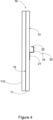
- the demountable wall system 100 comprises a first and a second demountable partition panel 10,10'.
- the first and second demountable partition panels 10, 10' are arranged spaced apart with the rear sides 13,13' facing each other such that the at least one panel mount bracket 20, 20' of the respective first and second demountable partition panel 10. 10' form at least one pair of aligned panel mount brackets 20, 20'.
- the demountable wall system 100 further comprises the flange connection element 15 connecting the at least one pair of aligned mount brackets 20,20'.
- the demountable wall partition system 100 may comprise a plurality of these first and second demountable partition panels 10,10' arranged next to each other forming a continuous partition wall structure.
- the flange connection element 15 may be an elongated profile configured to receive the second end flanges 22, 22' of the pair of aligned mount brackets 20, 20'.
- the elongated profile has a C-shaped cross section.
- the flange connection element 15 may have any length. The length of the flange connection element 15 may for instance be long enough to cover at least two adjacent pairs of aligned mount brackets 20,20', illustrated in Fig 9 .
- Two adjoining flange connection elements 15 may as illustrated in Fig. 9 form a joint at a common pair of aligned panel mount brackets 20, thereby improving the rigidity of the demountable wall partition system 100.
- the flange connection element 15 may be shaped, for example the elongated C-shaped profile, such that the flange connection element can be slid over and connecting the second end flanges 22, 22' of the pair of aligned mount brackets 20, 20'.
- the slidable flange connection element 15 facilitates assembly of the demountable wall partition system 100 since any person could simply slide the flange connection element 15 from an open side of the demountable wall partition system 100, in between the demountable partition panels 10 to connect them.
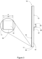
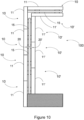
- the flange connection element 15 may in other examples have a length and being arranged such that the flange connection element 15 partly covers and connects the second end flanges 22, 22', illustrated in e.g. Fig. 10.
- Fig.10 illustrates how the flange connection element 15 starts at a top corner of a wall assembled by several demountable partition panels 10 and runs downward over a first pair of second end flanges 22, 22' of a pair of aligned mount brackets 20, 20' and midway to a second pair of second end flanges 22, 22' of the pair of aligned mount brackets 20, 20'.
- the flange connection element 15 may also be a clip or have a length that is smaller than a width of the second end flanges 22, 22'.
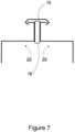
- the gasket 16 may be arranged between the pair of aligned panel mount brackets 20, 20', illustrated in Fig. 7 .
- the gasket 16 may be pre-attached to one of the second end flanges 22, 22' by for example glue or the gasket 16 may be arranged in between the panel mount brackets 20, 20' when assembling the demountable wall partition system 100.
- the size of the gasket 16 may be varied depending on for example a desired acoustic dampening between the first and second demountable partition panels 10, 10'.
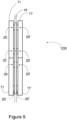
- Fig. 8 illustrates the demountable wall partition system 100 in place between a ceiling and a floor and having two pairs of aligned mount brackets 20, 20' at different heights. Attaching the demountable wall partition system 100 may be performed with runners attached to the ceiling and/or floor. Other ways of securing the wall from movement and maintaining the office area could be with brackets or block in the ceiling and/or on the floor.
- the demountable wall partition panels 10, 10' are installed or assembled into the demountable wall partition system 100 by arranging a first and a second demountable partition panel 10, 10' such that the panel mount bracket 20 of the first demountable partition panel opposes the panel mount bracket 20' of the second demountable partition panel 10'.
- This can for example be done by standing the first demountable partition panel 10 on the floor of the office space being constructed in an upright manner more or less in a perpendicular direction to the floor of the office space.
- the second partition panel 10' then also raised in an upright direction, being more or less perpendicular to the floor of the office space such that the pane mount brackets 20,20' are opposing each other.
- first and second panel mount brackets 20,20' may abut each other or there may be a slight gap in between the first and second panel mount brackets 20,20', or the gasket 16 may be arrganged between the first and second panel mount brackets 20,20'.
- the first and second panel mount brackets 20, 20' are then connected by means of the flange connection element 15. This connection can be done by sliding, as disucussed above, or clamping the flange connection element 15 with the first and second panel mount brackets 20,20'.
- the connection by the flange connection element 15 holds together the first and second partition panels 10,10' in the upright position and so that they are not separated from each other but forms separate inner wall portions.
- the panel mount bracket 20 of the first demountable partition panel may be level with and/or directly opposed to the panel mount bracket 20' of the second demountable partition panel 10'.
- the demountable wall partition system 100 comprises in some examples an insulating material arranged in the void between the first and second demountable partition panels 10,10'.
- the insulating material may be arranged in bags and which then can easily be put in the void but also removed later for reuse. It is also additionally possible to run other types of installations in the void such as electrical, plumbing, data and so on, alone or in combination with the insulating material.
- Figs. 9 and 10 Illustrated in Figs. 9 and 10 are two examples of how to possibly arrange the demountable partition panels 10, 10' for accommodating different room layouts and/or accounting for already existing structural elements in a building.
- Fig. 9 illustrates that the demountable partition panels 10, 10' can be arranged more or less perfectly opposite each other when forming the wall.
- Fig. 10 illustrates another setup wherein the demountable partition panels 10, 10' are arranged in an off-set pattern, but still with the panel mount brackets 20, 20' opposite each other, to accommodate a fixed structural element such as an outer wall of the building that the demountable wall partition system 100 is being built in.
- Other arrangements are of course possible such as for example demountable partition panels 10, 10' having different widths and/or height.
Landscapes
- Engineering & Computer Science (AREA)
- Architecture (AREA)
- Physics & Mathematics (AREA)
- Electromagnetism (AREA)
- Civil Engineering (AREA)
- Structural Engineering (AREA)
- Connection Of Plates (AREA)
- Vehicle Step Arrangements And Article Storage (AREA)
- Connector Housings Or Holding Contact Members (AREA)
Claims (14)
- Demontierbares Trennwandsystem (100), umfassendein erstes und ein zweites demontierbares Trennpaneel (10, 10') undein Flanschverbindungselement (15),wobei sowohl das erste als auch das zweite abnehmbare Trennpaneel (10, 10') eine vordere Fläche (12, 12'), eine hintere Fläche (13, 13') und Seitenränder (14) aufweist, die die vordere Fläche (12, 12') und die hintere Fläche (13, 13') verbinden, und eine Platte (11, 11') mit einer hinteren Fläche (13, 13'), die die hintere Fläche (13, 13') des zugehörigen demontierbaren Trennpaneels (10, 10') bildet, und mindestens eine Paneel-Monatgehalterung (20, 20'), die mit der Platte (11, 11') verbunden ist und von der hinteren Fläche (13, 13') vorsteht, umfasst, wobei die mindestens eine Paneel-Montaghalterung (20, 20') einen ersten Endflansch (21), der sich in einer ersten Flanschebene parallel zu der hinteren Fläche (13, 13') der Platte (11, 11') erstreckt, und einen zweiten Endflansch (22) umfasst,wobei das erste und das zweite demontierbare Trennpaneel (10, 10') voneinander beabstandet angeordnet sind, wobei die Rückseiten (13, 13') einander derart zugewandt sind, dass die mindestens eine Paneel-Monatgehalterung (20, 20') des jeweiligen ersten und zweiten demontierbaren Trennpaneels (10, 10') mindestens ein Paar ausgerichteter Paneel-Monatgehalterungen (20, 20') bildet,wobei die Platte (11) des ersten und/oder des zweiten demontierbaren Trennpaneels (10, 10') eine Gipsplatte und noch bevorzugter eine verstärkte Gipsplatte ist,dadurch gekennzeichnet, dassdas mindestens eine Paar ausgerichteter Paneel-Monatgehalterungen (20, 20') mittels des Flanschverbindungselements (15) miteinander verbunden sind, das mit den zweiten Endflanschen (22) des mindestens einen Paars ausgerichteter Paneel-Monatgehalterungen (20, 20') derart verbunden ist, dass das Flanschverbindungselement (15) von dem mindestens einen Paar ausgerichteter Paneel-Monatgehalterungen (20, 20') getragen ist.
- Demontierbares Trennwandsystem (100) nach Anspruch 1,
wobei der erste Endflansch (21) der mindestens einen Paneel-Monatgehalterung (20) des ersten und zweiten demontierbaren Trennpaneels (10, 10') an der hinteren Fläche (13, 13') der Platte (11) angebracht ist. - Demontierbares Trennwandsystem (100) nach Anspruch 1 oder 2, wobei das erste und/oder das zweite demontierbare Trennpaneel (10, 10') eine Randabdeckung (30) umfasst, wobei die Randabdeckung (30) die Seitenränder (14) zumindest teilweise abdeckt.
- Demontierbares Trennwandsystem (100) nach Anspruch 3, wobei die Randabdeckung (30) eine Rahmenstruktur bildet.
- Demontierbares Trennwandsystem (100) nach Anspruch 3 oder 4, wobei die Randabdeckung (30) ein L-förmiges Profil umfasst, das sich entlang eines der Seitenränder (14) erstreckt, wobei das L-förmige Profil einen Flansch umfasst, der sich parallel zu dem einen Seitenrand erstreckt, und eine Breite aufweist, die kleiner ist als eine Dicke des zugehörigen demontierbaren Trennpaneels (10, 10').
- Demontierbares Trennwandsystem (100) nach einem der vorhergehenden Ansprüche, wobei das erste und/oder das zweite demontierbare Trennpaneel (10, 10') eine zusätzliche Platte (110) umfasst, die einer vorderen Fläche (12) der Platte (11) zugewandt ist.
- Demontierbares Trennwandsystem (100) nach Anspruch 6, wobei die Platte (11) und die zusätzliche Platte (110) miteinander verklebt sind.
- Demontierbares Trennwandsystem (100) nach einem der vorhergehenden Ansprüche, umfassend eine Dichtung (16), die zwischen dem mindestens einen Paar ausgerichteter Paneel-Monatgehalterungen (20, 20') angeordnet ist.
- Demontierbares Trennwandsystem (100) nach einem der vorhergehenden Ansprüche, wobei sich die zweiten Endflansche (22) des mindestens einen Paars ausgerichteter Paneel-Monatgehalterungen (20, 20') jeweils in einer Richtung erstrecken, die eine Komponente aufweist, die senkrecht zu der hinteren Fläche (13) der Platte (11) ist.
- Demontierbares Trennwandsystem (100) nach Anspruch 9, wobei sich jeder zweite Endflansch (22) von einer ersten Position in Richtung einer zweiten Position erstreckt, die einem freien Ende des zweiten Endflansches (22) entspricht, das von der hinteren Fläche (13) der Platte (11) beabstandet ist, wobei ein Abstand zwischen der hinteren Fläche (13) und der zweiten Position größer ist als ein Abstand zwischen der hinteren Fläche (13) und der ersten Position.
- Demontierbares Trennwandsystem (100) nach einem der vorhergehenden Ansprüche, wobei das Flanschverbindungselement (15) ein längliches Profil ist, das eingerichtet ist, um die zweiten Endflansche (22, 22') des Paars ausgerichteter Paneel-Monatgehalterungen (20, 20') aufzunehmen.
- Demontierbares Trennwandsystem (100) nach 11, wobei das längliche Profil einen C-förmigen Querschnitt aufweist.
- Demontierbares Trennwandsystem (100) nach einem der vorhergehenden Ansprüche, ferner umfassend ein Isoliermaterial, das in einem Hohlraum angeordnet ist, der zwischen dem ersten und dem zweiten demontierbaren Trennpaneel (10, 10') gebildet ist.
- Verfahren zum Installieren eines demontierbaren Trennwandsystems nach einem der Ansprüche 1-13, umfassendAnordnen des ersten und des zweiten demontierbaren Trennpaneels (10), sodass die Paneel-Monatgehalterung (20) des ersten demontierbaren Trennpaneels der Paneel-Monatgehalterung (20') des zweiten demontierbaren Trennpaneels (10') gegenüberliegt, wodurch mindestens ein Paar ausgerichteter Paneel-Monatgehalterungen gebildet wird,Verbinden des Flanschverbindungselements (15) mit den zweiten Endflanschen (22) des mindestens einen Paars ausgerichteter Paneel-Monatgehalterungen (20, 20') derart, dass das Flanschverbindungselement (15) von dem mindestens einen Paar ausgerichteter Paneel-Monatgehalterungen (20, 20') getragen ist.
Priority Applications (4)
| Application Number | Priority Date | Filing Date | Title |
|---|---|---|---|
| EP20200055.0A EP3978699B1 (de) | 2020-10-05 | 2020-10-05 | Demontierbare trennwandsystem |
| US18/247,398 US20230407630A1 (en) | 2020-10-05 | 2021-10-04 | Demountable wall partition system |
| CA3194261A CA3194261A1 (en) | 2020-10-05 | 2021-10-04 | Demountable wall partition system |
| PCT/EP2021/077259 WO2022073911A1 (en) | 2020-10-05 | 2021-10-04 | Demountable wall partition system |
Applications Claiming Priority (1)
| Application Number | Priority Date | Filing Date | Title |
|---|---|---|---|
| EP20200055.0A EP3978699B1 (de) | 2020-10-05 | 2020-10-05 | Demontierbare trennwandsystem |
Publications (3)
| Publication Number | Publication Date |
|---|---|
| EP3978699A1 EP3978699A1 (de) | 2022-04-06 |
| EP3978699B1 true EP3978699B1 (de) | 2025-01-29 |
| EP3978699C0 EP3978699C0 (de) | 2025-01-29 |
Family
ID=72752324
Family Applications (1)
| Application Number | Title | Priority Date | Filing Date |
|---|---|---|---|
| EP20200055.0A Active EP3978699B1 (de) | 2020-10-05 | 2020-10-05 | Demontierbare trennwandsystem |
Country Status (4)
| Country | Link |
|---|---|
| US (1) | US20230407630A1 (de) |
| EP (1) | EP3978699B1 (de) |
| CA (1) | CA3194261A1 (de) |
| WO (1) | WO2022073911A1 (de) |
Family Cites Families (3)
| Publication number | Priority date | Publication date | Assignee | Title |
|---|---|---|---|---|
| GB1120632A (en) * | 1964-09-28 | 1968-07-24 | William Mallinson & Sons Ltd | Improvements in or relating to partitions comprising demountable panels |
| CA1002279A (en) * | 1972-08-03 | 1976-12-28 | Reginald S. Price | Partition system for a building |
| DE8501877U1 (de) * | 1985-01-25 | 1986-08-14 | Ph. Kurtz Eisenhammer KG, 6981 Hasloch | Als Schalung ausgebildetes Bauelement |
-
2020
- 2020-10-05 EP EP20200055.0A patent/EP3978699B1/de active Active
-
2021
- 2021-10-04 CA CA3194261A patent/CA3194261A1/en active Pending
- 2021-10-04 WO PCT/EP2021/077259 patent/WO2022073911A1/en not_active Ceased
- 2021-10-04 US US18/247,398 patent/US20230407630A1/en active Pending
Also Published As
| Publication number | Publication date |
|---|---|
| WO2022073911A1 (en) | 2022-04-14 |
| US20230407630A1 (en) | 2023-12-21 |
| EP3978699A1 (de) | 2022-04-06 |
| CA3194261A1 (en) | 2022-04-14 |
| EP3978699C0 (de) | 2025-01-29 |
Similar Documents
| Publication | Publication Date | Title |
|---|---|---|
| US5822935A (en) | Solid-core wall system | |
| US7621096B2 (en) | Construction blocking bracket | |
| US6308491B1 (en) | Structural insulated panel | |
| EP1989362B1 (de) | Wärmedämmsystem aus an eine Wand angeordneten miteinander verbundenen Isolierpaneelen | |
| US7162847B2 (en) | Apparatus and method for fabricating foam wall panels | |
| EP3601689B1 (de) | Paneel für eine trennwand | |
| US10773882B2 (en) | Shipping container insulation panel and installation method | |
| US7810294B2 (en) | Housing construction system | |
| US3922830A (en) | Adjustable modular partition | |
| US4458462A (en) | Movable wall assembly | |
| US12252880B2 (en) | System and method for insulating an intermodal container | |
| FI74771B (fi) | Anordning vid ytbildande skiva. | |
| EP3978699B1 (de) | Demontierbare trennwandsystem | |
| EP3999696B1 (de) | Ineinandergreifende flächige bauprodukte aus gips, verfahren zu ihrer herstellung | |
| US11814844B2 (en) | Building stud, wall structure comprising such a building stud and a method for forming a wall structure | |
| CN217000333U (zh) | 一种隔墙系统及龙骨 | |
| US11661748B2 (en) | Method for producing a facing | |
| EP3219869B1 (de) | Befestigungselement und wandelement eines gebäudes | |
| EP0921245A1 (de) | Wandpaneel für Innenwandvorrichtung und Verbindungselement dazu | |
| US20250354388A1 (en) | Interlocking surface panel clips | |
| CN219451167U (zh) | 一种隔墙结构 | |
| JP7777791B2 (ja) | パネル装置 | |
| WO2002095162A1 (en) | Brick slip fixture system | |
| EP0665920A1 (de) | Verbindungselement und dessen anwendung | |
| JP2001032419A (ja) | 間仕切りパネルの取付構造とその施工方法 |
Legal Events
| Date | Code | Title | Description |
|---|---|---|---|
| PUAI | Public reference made under article 153(3) epc to a published international application that has entered the european phase |
Free format text: ORIGINAL CODE: 0009012 |
|
| STAA | Information on the status of an ep patent application or granted ep patent |
Free format text: STATUS: THE APPLICATION HAS BEEN PUBLISHED |
|
| AK | Designated contracting states |
Kind code of ref document: A1 Designated state(s): AL AT BE BG CH CY CZ DE DK EE ES FI FR GB GR HR HU IE IS IT LI LT LU LV MC MK MT NL NO PL PT RO RS SE SI SK SM TR |
|
| STAA | Information on the status of an ep patent application or granted ep patent |
Free format text: STATUS: REQUEST FOR EXAMINATION WAS MADE |
|
| 17P | Request for examination filed |
Effective date: 20221005 |
|
| RBV | Designated contracting states (corrected) |
Designated state(s): AL AT BE BG CH CY CZ DE DK EE ES FI FR GB GR HR HU IE IS IT LI LT LU LV MC MK MT NL NO PL PT RO RS SE SI SK SM TR |
|
| GRAP | Despatch of communication of intention to grant a patent |
Free format text: ORIGINAL CODE: EPIDOSNIGR1 |
|
| STAA | Information on the status of an ep patent application or granted ep patent |
Free format text: STATUS: GRANT OF PATENT IS INTENDED |
|
| INTG | Intention to grant announced |
Effective date: 20240913 |
|
| GRAS | Grant fee paid |
Free format text: ORIGINAL CODE: EPIDOSNIGR3 |
|
| GRAA | (expected) grant |
Free format text: ORIGINAL CODE: 0009210 |
|
| STAA | Information on the status of an ep patent application or granted ep patent |
Free format text: STATUS: THE PATENT HAS BEEN GRANTED |
|
| AK | Designated contracting states |
Kind code of ref document: B1 Designated state(s): AL AT BE BG CH CY CZ DE DK EE ES FI FR GB GR HR HU IE IS IT LI LT LU LV MC MK MT NL NO PL PT RO RS SE SI SK SM TR |
|
| REG | Reference to a national code |
Ref country code: GB Ref legal event code: FG4D |
|
| REG | Reference to a national code |
Ref country code: CH Ref legal event code: EP |
|
| REG | Reference to a national code |
Ref country code: DE Ref legal event code: R096 Ref document number: 602020045438 Country of ref document: DE |
|
| REG | Reference to a national code |
Ref country code: IE Ref legal event code: FG4D |
|
| U01 | Request for unitary effect filed |
Effective date: 20250129 |
|
| U07 | Unitary effect registered |
Designated state(s): AT BE BG DE DK EE FI FR IT LT LU LV MT NL PT RO SE SI Effective date: 20250204 |
|
| PG25 | Lapsed in a contracting state [announced via postgrant information from national office to epo] |
Ref country code: RS Free format text: LAPSE BECAUSE OF FAILURE TO SUBMIT A TRANSLATION OF THE DESCRIPTION OR TO PAY THE FEE WITHIN THE PRESCRIBED TIME-LIMIT Effective date: 20250429 |
|
| PG25 | Lapsed in a contracting state [announced via postgrant information from national office to epo] |
Ref country code: PL Free format text: LAPSE BECAUSE OF FAILURE TO SUBMIT A TRANSLATION OF THE DESCRIPTION OR TO PAY THE FEE WITHIN THE PRESCRIBED TIME-LIMIT Effective date: 20250129 |
|
| PG25 | Lapsed in a contracting state [announced via postgrant information from national office to epo] |
Ref country code: ES Free format text: LAPSE BECAUSE OF FAILURE TO SUBMIT A TRANSLATION OF THE DESCRIPTION OR TO PAY THE FEE WITHIN THE PRESCRIBED TIME-LIMIT Effective date: 20250129 |
|
| PG25 | Lapsed in a contracting state [announced via postgrant information from national office to epo] |
Ref country code: IS Free format text: LAPSE BECAUSE OF FAILURE TO SUBMIT A TRANSLATION OF THE DESCRIPTION OR TO PAY THE FEE WITHIN THE PRESCRIBED TIME-LIMIT Effective date: 20250529 |
|
| PG25 | Lapsed in a contracting state [announced via postgrant information from national office to epo] |
Ref country code: HR Free format text: LAPSE BECAUSE OF FAILURE TO SUBMIT A TRANSLATION OF THE DESCRIPTION OR TO PAY THE FEE WITHIN THE PRESCRIBED TIME-LIMIT Effective date: 20250129 |
|
| PG25 | Lapsed in a contracting state [announced via postgrant information from national office to epo] |
Ref country code: GR Free format text: LAPSE BECAUSE OF FAILURE TO SUBMIT A TRANSLATION OF THE DESCRIPTION OR TO PAY THE FEE WITHIN THE PRESCRIBED TIME-LIMIT Effective date: 20250430 |
|
| PG25 | Lapsed in a contracting state [announced via postgrant information from national office to epo] |
Ref country code: SM Free format text: LAPSE BECAUSE OF FAILURE TO SUBMIT A TRANSLATION OF THE DESCRIPTION OR TO PAY THE FEE WITHIN THE PRESCRIBED TIME-LIMIT Effective date: 20250129 |
|
| U20 | Renewal fee for the european patent with unitary effect paid |
Year of fee payment: 6 Effective date: 20250909 |
|
| PGFP | Annual fee paid to national office [announced via postgrant information from national office to epo] |
Ref country code: GB Payment date: 20250904 Year of fee payment: 6 |
|
| PG25 | Lapsed in a contracting state [announced via postgrant information from national office to epo] |
Ref country code: CZ Free format text: LAPSE BECAUSE OF FAILURE TO SUBMIT A TRANSLATION OF THE DESCRIPTION OR TO PAY THE FEE WITHIN THE PRESCRIBED TIME-LIMIT Effective date: 20250129 |
|
| PG25 | Lapsed in a contracting state [announced via postgrant information from national office to epo] |
Ref country code: SK Free format text: LAPSE BECAUSE OF FAILURE TO SUBMIT A TRANSLATION OF THE DESCRIPTION OR TO PAY THE FEE WITHIN THE PRESCRIBED TIME-LIMIT Effective date: 20250129 |
|
| REG | Reference to a national code |
Ref country code: CH Ref legal event code: U11 Free format text: ST27 STATUS EVENT CODE: U-0-0-U10-U11 (AS PROVIDED BY THE NATIONAL OFFICE) Effective date: 20251101 |