EP3978689A1 - Construction machine - Google Patents
Construction machine Download PDFInfo
- Publication number
- EP3978689A1 EP3978689A1 EP20813928.7A EP20813928A EP3978689A1 EP 3978689 A1 EP3978689 A1 EP 3978689A1 EP 20813928 A EP20813928 A EP 20813928A EP 3978689 A1 EP3978689 A1 EP 3978689A1
- Authority
- EP
- European Patent Office
- Prior art keywords
- vertical plate
- plate
- opening
- engine
- turning
- Prior art date
- Legal status (The legal status is an assumption and is not a legal conclusion. Google has not performed a legal analysis and makes no representation as to the accuracy of the status listed.)
- Granted
Links
Images



Classifications
-
- E—FIXED CONSTRUCTIONS
- E02—HYDRAULIC ENGINEERING; FOUNDATIONS; SOIL SHIFTING
- E02F—DREDGING; SOIL-SHIFTING
- E02F9/00—Component parts of dredgers or soil-shifting machines, not restricted to one of the kinds covered by groups E02F3/00 - E02F7/00
- E02F9/08—Superstructures; Supports for superstructures
-
- E—FIXED CONSTRUCTIONS
- E02—HYDRAULIC ENGINEERING; FOUNDATIONS; SOIL SHIFTING
- E02F—DREDGING; SOIL-SHIFTING
- E02F9/00—Component parts of dredgers or soil-shifting machines, not restricted to one of the kinds covered by groups E02F3/00 - E02F7/00
- E02F9/08—Superstructures; Supports for superstructures
- E02F9/10—Supports for movable superstructures mounted on travelling or walking gears or on other superstructures
- E02F9/12—Slewing or traversing gears
- E02F9/121—Turntables, i.e. structure rotatable about 360°
- E02F9/123—Drives or control devices specially adapted therefor
-
- E—FIXED CONSTRUCTIONS
- E02—HYDRAULIC ENGINEERING; FOUNDATIONS; SOIL SHIFTING
- E02F—DREDGING; SOIL-SHIFTING
- E02F9/00—Component parts of dredgers or soil-shifting machines, not restricted to one of the kinds covered by groups E02F3/00 - E02F7/00
- E02F9/08—Superstructures; Supports for superstructures
- E02F9/0808—Improving mounting or assembling, e.g. frame elements, disposition of all the components on the superstructures
-
- E—FIXED CONSTRUCTIONS
- E02—HYDRAULIC ENGINEERING; FOUNDATIONS; SOIL SHIFTING
- E02F—DREDGING; SOIL-SHIFTING
- E02F9/00—Component parts of dredgers or soil-shifting machines, not restricted to one of the kinds covered by groups E02F3/00 - E02F7/00
- E02F9/08—Superstructures; Supports for superstructures
- E02F9/0808—Improving mounting or assembling, e.g. frame elements, disposition of all the components on the superstructures
- E02F9/0816—Welded frame structure
-
- E—FIXED CONSTRUCTIONS
- E02—HYDRAULIC ENGINEERING; FOUNDATIONS; SOIL SHIFTING
- E02F—DREDGING; SOIL-SHIFTING
- E02F9/00—Component parts of dredgers or soil-shifting machines, not restricted to one of the kinds covered by groups E02F3/00 - E02F7/00
- E02F9/08—Superstructures; Supports for superstructures
- E02F9/0858—Arrangement of component parts installed on superstructures not otherwise provided for, e.g. electric components, fenders, air-conditioning units
-
- E—FIXED CONSTRUCTIONS
- E02—HYDRAULIC ENGINEERING; FOUNDATIONS; SOIL SHIFTING
- E02F—DREDGING; SOIL-SHIFTING
- E02F9/00—Component parts of dredgers or soil-shifting machines, not restricted to one of the kinds covered by groups E02F3/00 - E02F7/00
- E02F9/08—Superstructures; Supports for superstructures
- E02F9/0858—Arrangement of component parts installed on superstructures not otherwise provided for, e.g. electric components, fenders, air-conditioning units
- E02F9/0866—Engine compartment, e.g. heat exchangers, exhaust filters, cooling devices, silencers, mufflers, position of hydraulic pumps in the engine compartment
-
- E—FIXED CONSTRUCTIONS
- E02—HYDRAULIC ENGINEERING; FOUNDATIONS; SOIL SHIFTING
- E02F—DREDGING; SOIL-SHIFTING
- E02F9/00—Component parts of dredgers or soil-shifting machines, not restricted to one of the kinds covered by groups E02F3/00 - E02F7/00
- E02F9/08—Superstructures; Supports for superstructures
- E02F9/10—Supports for movable superstructures mounted on travelling or walking gears or on other superstructures
- E02F9/12—Slewing or traversing gears
- E02F9/121—Turntables, i.e. structure rotatable about 360°
- E02F9/126—Lubrication systems
-
- E—FIXED CONSTRUCTIONS
- E02—HYDRAULIC ENGINEERING; FOUNDATIONS; SOIL SHIFTING
- E02F—DREDGING; SOIL-SHIFTING
- E02F9/00—Component parts of dredgers or soil-shifting machines, not restricted to one of the kinds covered by groups E02F3/00 - E02F7/00
- E02F9/20—Drives; Control devices
- E02F9/22—Hydraulic or pneumatic drives
- E02F9/2264—Arrangements or adaptations of elements for hydraulic drives
- E02F9/2275—Hoses and supports therefor and protection therefor
-
- E—FIXED CONSTRUCTIONS
- E02—HYDRAULIC ENGINEERING; FOUNDATIONS; SOIL SHIFTING
- E02F—DREDGING; SOIL-SHIFTING
- E02F3/00—Dredgers; Soil-shifting machines
- E02F3/04—Dredgers; Soil-shifting machines mechanically-driven
- E02F3/28—Dredgers; Soil-shifting machines mechanically-driven with digging tools mounted on a dipper- or bucket-arm, i.e. there is either one arm or a pair of arms, e.g. dippers, buckets
- E02F3/30—Dredgers; Soil-shifting machines mechanically-driven with digging tools mounted on a dipper- or bucket-arm, i.e. there is either one arm or a pair of arms, e.g. dippers, buckets with a dipper-arm pivoted on a cantilever beam, i.e. boom
- E02F3/32—Dredgers; Soil-shifting machines mechanically-driven with digging tools mounted on a dipper- or bucket-arm, i.e. there is either one arm or a pair of arms, e.g. dippers, buckets with a dipper-arm pivoted on a cantilever beam, i.e. boom working downwardly and towards the machine, e.g. with backhoes
- E02F3/325—Backhoes of the miniature type
-
- E—FIXED CONSTRUCTIONS
- E02—HYDRAULIC ENGINEERING; FOUNDATIONS; SOIL SHIFTING
- E02F—DREDGING; SOIL-SHIFTING
- E02F9/00—Component parts of dredgers or soil-shifting machines, not restricted to one of the kinds covered by groups E02F3/00 - E02F7/00
- E02F9/08—Superstructures; Supports for superstructures
- E02F9/0858—Arrangement of component parts installed on superstructures not otherwise provided for, e.g. electric components, fenders, air-conditioning units
- E02F9/0883—Tanks, e.g. oil tank, urea tank, fuel tank
Definitions
- the present invention relates to a construction machine.
- a construction machine such as a backhoe, includes a lower traveling body, an upper turning body provided capable of turning above the lower traveling body, and a work machine that is supported vertically rotatably at the front of the upper turning body.
- Patent Literature 1 discloses, as a pump suction piping structure of a construction machine, a technology for routing a suction hose by being passed through left and right vertical plates extending in a front-rear direction of the upper turning body and by being followed along a partition plate dividing the vertical plates.
- Patent Literature 2 discloses, as a pump suction piping structure of a construction machine, a technology for routing a suction hose by being passed through the left and right vertical plates extending in the front-rear directions of the upper turning body, and by further being passed through the partition plate dividing the vertical plates.
- the present invention was made in view of the above circumstances, an object of which is to provide a construction machine capable of increasing a degree of freedom of a piping layout while securing rigidity of a turning frame in the upper turning body.
- the construction machine of the present invention includes a lower traveling body, an upper turning body provided capable of turning above the lower traveling body, an engine disposed at a rear part of the upper turning body, and a turning frame that constitutes the bottom part of the upper turning body and on which the engine is mounted, in which the turning frame has a bottom plate, a left and right pair of a first vertical plate and a second vertical plate provided upright on the bottom plate so as to extend in the front-rear direction, and a coupling member connected to the first and second vertical plates and dividing a space between the first and second vertical plates, the coupling member includes at least a top plate and a pair of front and rear side plates extending downwardly from front and rear ends of the top plate, and forms a box shape structure together with the first vertical plate and the second vertical plate, and the box shape structure has a first opening formed through the first vertical plate, a second opening formed through the second vertical plate, and an engine support part formed in the top plate.
- a third opening open to the front may be formed through the box shape structure.
- the construction machine of the present invention has a hydraulic pump driven by the engine, a suction port of the hydraulic pump disposed on the left and right outer sides of the second vertical plate, and a hydraulic oil tank disposed on the left and right outer sides of the first vertical plate, and a suction hose connecting the suction port to the hydraulic oil tank may be inserted through the first and second openings.
- the construction machine of the present invention also has a grease nipple disposed on the left and right outer sides of the first vertical plate and a grease supply port for a turning bearing disposed on the left and right outer sides of the second vertical plate, and a grease hose connecting the grease nipple to the grease supply port may be inserted through the second opening and the third opening.
- pipes such as various hoses can be routed across the turning frame in the left-right direction while passing under the engine without reducing the rigidity of the turning frame by routing the pipes by using an internal space of the box shape structure.
- a degree of freedom of the piping layout can be increased while securing the rigidity of the turning frame in the upper turning body.
- a construction machine 1 includes a lower traveling body 2, an upper turning body 3 provided capable of turning above the lower traveling body 2, a boom bracket 4 which is a swinging body supported horizontally rotatably by the upper turning body 3, and a work machine 5 which is supported vertically rotatably by the boom bracket 4.
- the construction machine 1 is configured as an excavator (backhoe) with a boom swing function.
- the boom swing function is provided in a compact excavator in which workability in a narrow space is required.
- the lower traveling body 2 is driven by power from an engine 60 (see FIG. 2 ) to travel and turn the construction machine 1.
- the lower traveling body 2 includes a left and right pair of crawlers 21 and 21, and a left and right pair of traveling motors 22 and 22 for driving the aforementioned crawlers 21 and 21.
- the lower traveling body 2 also includes a blade 23.
- the upper turning body 3 is constituted capable of performing a turning operation around an axis extending in a vertical direction at a center part thereof.
- the upper turning body 3 has an engine 60, a turning motor 61 (see FIG. 2 ), a maneuvering unit 62 and the like disposed.
- the maneuvering unit 62 is equipped with a driver's seat and operating devices.
- the boom bracket 4 is mounted at a front end of the upper turning body 3 via a mounting portion 35.
- the boom bracket 4 is supported by the mounting portion 35 in a horizontally rotatably (that is, laterally swingable manner).
- a swing cylinder (not shown), which performs an extending / contracting motion in a front-rear direction, is provided between the upper turning body 3 and the boom bracket 4. The horizontal rotation of the boom bracket 4 is performed in accordance with the extension and contraction of the swing cylinder.
- the work machine 5 is driven by power from the engine 60 and performs an excavation work of earth and sand and the like in response to an operation at the maneuvering unit 62.
- the work machine 5 is supported on the boom bracket 4 vertically rotatably.
- the boom bracket 4 has a pivot pin 54 with an axis directed toward the horizontal direction provided.
- Abase end of the work machine 5 base end of a boom 51 described later
- the work machine 5 is capable of performing a swing motion in conjunction with the horizontal rotation of the boom bracket 4.
- the work machine 5 includes the boom 51, an arm 52, and a bucket 53.
- the boom 51 is mounted on the boom bracket 4 vertically rotatably.
- the boom 51 vertically extends in the vertical direction from the base end thereof supported by the boom bracket 4, and is curved in a boomerang shape in a side view.
- a boom cylinder 51a which is movable in an extensible and contractible manner, is provided between the boom bracket 4 and an intermediate portion of the boom 51. The vertical rotation of the boom 51 with respect to the boom bracket 4 is performed in accordance with the extension and contraction of the boom cylinder 51a.
- the arm 52 is mounted on the boom 51 vertically rotatably.
- a pivot pin 55 having an axis directed toward the horizontal direction is provided at a distal end of the boom 51.
- a base end of the arm 52 is supported vertically rotatably (rotatably back and forth) around the pivot pin 55.
- An arm cylinder 52a which is movable in an extensible and contractible manner, is provided between an intermediate portion of the boom 51 and the base end of the arm 52. The vertical rotation of the arm 52 with respect to the boom 51 is performed in accordance with the extension and contraction of the arm cylinder 52a.
- the bucket 53 is mounted on the arm 52 vertically rotatably.
- a pivot pin 56 having an axis directed toward the horizontal direction is provided at a distal end of the arm 52.
- Abase end of the bucket 53 is supported capable of vertical rotation (back and forth rotation) around the pivot pin 56.
- a bucket link 57 is interposed between the distal end of the arm 52 and the bucket 53.
- the bucket link 57 is configured as a link for transmitting a driving force to the bucket 53.
- a bucket cylinder 53a which is movable in an extensible and contractible manner, is provided between the bucket link 57 and the base end of the arm 52. The vertical rotation of the bucket 53 with respect to the arm 52 is performed in accordance with the extension and contraction of the bucket cylinder 53a.
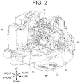
- FIG. 2 is a perspective view illustrating an internal structure of the upper turning body 3.
- the engine 60, a battery, a fuel tank and the like are placed on a turning frame 30, these are covered by a bonnet 66, and the maneuvering unit 62 is disposed at the front thereof.
- a hydraulic pump 63 is connected to the engine 60, and the hydraulic pump 63 is driven by the engine 60 and discharges the hydraulic oil.
- the hydraulic oil discharged from the hydraulic pump 63 is supplied to the swing cylinder, the boom cylinder 51a, the arm cylinder 52a, the bucket cylinder 53a, a blade cylinder, the traveling motors 22, 22, the turning motor 61 and the like via hydraulic hoses, the control unit and the like
- the turning frame 30 includes a flat plate-shaped bottom plate 31, a left and right pair of a first vertical plate 32 and a second vertical plate 33 provided upright on the bottom plate 31 so as to extend in the front-rear direction, and a coupling member 34 connected to the first vertical plate 32 and the second vertical plate 33 and dividing a space between the first vertical plate 32 and the second vertical plate 33.
- the bottom plate 31 is circular with the front end cut out in the left-right direction on a plan view.
- the first vertical plate 32 and the second vertical plate 33 are located on the bottom plate 31 at an interval in the left-right direction, and are provided upright so as to extend in the front-rear direction.
- the first vertical plate 32 and the second vertical plate 33 are disposed to expand rearwardly.
- the first vertical plate 32 is disposed on the right side of the turning frame 30 from the center in the left-right direction
- the second vertical plate 33 is disposed on the left side of the turning frame 30 from the center in the left-right direction.
- the bottom plate 31 between the first vertical plate 32 and the second vertical plate 33 has a joint opening 31a into which a swivel joint is inserted and a motor mounting portion 31b for mounting the turning motor 61.
- a plurality of other openings for drainage and maintenance are formed through the bottom plate 31.
- the first vertical plate 32 and the second vertical plate 33 have their lower edges welded to the upper surface of the bottom plate 31.
- a front end 32a of the first vertical plate 32 and a front end 33a of the second vertical plate 33 protrude forward from the bottom plate 31 and constitute a part of the mounting portion 35.
- a rear end 32b of the first vertical plate 32 and a rear end 33b of the second vertical plate 33 are connected to a counterweight mounting portion 36.
- the counterweight mounting portion 36 is provided on a rear end of the bottom plate 31 along the left-right direction, and a counterweight 67 is mounted on the counterweight mounting portion 36.
- the coupling member 34 is connected to the first vertical plate 32 and the second vertical plate 33 behind the joint opening 31a.
- the coupling member 34 has a top plate 341 disposed along the horizontal direction and a pair of a front side plate 342 and a rear side plate 343 extending downwardly from the both ends in the front-rear direction of the top plate 341.
- the lower ends of the front side plate 342 and the rear side plate 343 are fixed to the bottom plate 31, and the front side plate 342 and the rear side plate 343 stand upright with respect to the bottom plate 31. That is, the coupling member 34 having a substantially U-shaped cross section with the lower side open forms a box shape structure 37 together with the bottom plate 31, the first vertical plate 32, and the second vertical plate 33.
- a first opening 32c is formed in the first vertical plate 32.
- the first opening 32c is formed by being notched on the lower part of the first vertical plate 32.
- the first opening 32c is formed on the right side of the coupling member 34 and is connected to an internal space of the coupling member 34.
- a second opening 33c is formed through the second vertical plate 33.
- the second opening 33c is formed by being notched on the lower part of the second vertical plate 33.
- the second opening 33c is formed on the left side of the coupling member 34 and is connected to the internal space of the coupling member 34.
- a third opening 34a open to the front is formed through the coupling member 34.
- the third opening 34a is formed by being notched from the front side plate 342 to the top plate 341.
- the top plate 341 of the coupling member 34 has a front engine support part 34b on which an engine mount 601 (see FIG. 2 ) is mounted.
- the front engine support parts 34b are formed on the right and left sides of the top plate 341, respectively.
- a pair of rear engine support parts 31c and 31c on which the engine mount 601 is mounted are provided, and the engine 60 is supported by the front engine support part 34b and the rear engine support part 31c.
- a mounting portion 35 on which the boom bracket 4 is mounted is provided so as to protrude forward.
- the mounting portion 35 has a tapered shape on a plan view, and an insertion hole 35a through which a pivot pin, not shown, is inserted is opened in the vertical direction at the front end thereof.
- the mounting portion 35 includes a pair of upper and lower stays 351, 352 spaced apart from each other.
- the pair of stays 351, 352 sandwich the front end 32a of the first vertical plate 32 and the front end 33a of the second vertical plate 33 from above and below.
- the lower stay 352 is attached to the front upper surface of the bottom plate 31 and protrudes forward from the front end of the bottom plate 31.
- a swing cylinder is disposed along the front-rear direction on the right side of the first vertical plate 32.
- a cylinder tube is rotatably supported by a cylinder mounting portion 38 formed in the turning frame 30, and a cylinder rod is rotatably connected to the boom bracket 4.
- the boom bracket 4 By extending and contracting the cylinder rod, the boom bracket 4 can be rotationally moved to the left and right. Accordingly, the swing cylinder swings left and right around the cylinder mounting portion 38.
- a control unit is disposed on the left side of the second vertical plate 33.
- the control unit has control valves that control operations of hydraulic cylinders (swing cylinder, boom cylinder 51a, arm cylinder 52a, bucket cylinder 53a, blade cylinder) and hydraulic motors (traveling motor 22, 22, turning motor 61) disposed.
- a hydraulic oil tank 64 is disposed on the right side of the first vertical plate 32.
- the hydraulic oil tank 64 stores the hydraulic oil of the hydraulic pump 63 and is connected to the hydraulic pump 63 by a suction hose 65.
- the hydraulic oil tank 64 is disposed at the center part in the front-rear direction of the right end of the turning frame 30. The lower end of the hydraulic oil tank 64 is fixed to the bottom plate 31.
- the hydraulic pump 63 includes a suction port 63a on the left side of the second vertical plate 33 on a plan view.
- One end of the suction hose 65 is connected to the lower part of the rear surface of the hydraulic oil tank 64, and the other end of the suction hose 65 is connected to the suction port 63a.
- the suction hose 65 is disposed to cross the turning frame 30 in the left-right direction through the inside of the box shape structure 37 disposed below the engine 60. In other words, the suction hose 65 runs from the hydraulic oil tank 64 through the box shape structure 37 to the hydraulic pump 63.
- the suction hose 65 is inserted through the first opening 32c and the second opening 33c.
- the upper turning body 3 turns with respect to the lower traveling body 2 via a turning bearing 39 (shown in dashed lines in FIG. 5 ).
- the turning bearing 39 is fixed to the bottom surface of the turning frame 30.
- a grease supply port 31d for the turning bearing is provided on the bottom plate 31 of the turning frame 30.
- the grease supply port 31d is formed on the left side of the second vertical plate 33.
- a grease hose 70 for supplying grease to the grease supply port 31d is inserted through the second opening 33c and the third opening 34a to a grease nipple 71 disposed on the right side of the first vertical plate 32.
- the grease injected from the grease nipple 71 reaches the grease supply port 31d via the grease hose 70 and is supplied to the turning bearing 39.
- the construction machine body 1 of the present embodiment includes the lower traveling body 2, the upper turning body 3 provided capable of turning above the lower traveling body 2, the engine 60 disposed at the rear of the upper turning body 3, the turning frame 30 constituting the bottom part of the upper turning body 3 and on which the engine 60 is mounted, the turning frame 30 includes the bottom plate 31, the left and right pair of the first vertical plate 32 and the second vertical plate 33 provided upright on the bottom plate 31 so as to extend in the front-rear direction, and the coupling member 34 connected to the first vertical plate 32 and the second vertical plate 33 and dividing the space between the first vertical plate 32 and the second vertical plate 33, the coupling member 34 includes at least the top plate 341 and the front and rear pair of the front side plate 342 and the rear side plate 343 extending downwardly from the both ends in the front-rear direction of the top plate 341, and forms the box shape structure 37 together with the first vertical plate 32 and the second vertical plate 33, and the box shape structure 37 has the first opening 32c formed through the first vertical plate 32, the second opening 33c formed
- the space between the first vertical plate 32 and the second vertical plate 33 of the turning frame 30 is divided by the box shape structure 37, and the pipes can be routed across the turning frame 30 in the left-right direction while passing under the engine 60 without reducing the rigidity of the turning frame 30 by routing the pipes such as various hoses by using the internal space of the box shape structure 37.
- a degree of freedom of the piping layout can be increased while securing the rigidity of the turning frame 30 in the upper turning body 3. This is particularly useful for a small-sized construction machine with a narrow space inside the bonnet 66.
- the box shape structure 37 preferably has the third opening 34a which is open to the front formed.
- the construction machine 1 also includes the hydraulic pump 63 driven by the engine 60, the suction port 63a of the hydraulic pump 63 disposed on the left side of the second vertical plate 33, and the hydraulic oil tank 64 disposed on the right side of the first vertical plate 32, and the suction hose 65 connecting the suction port 63a and the hydraulic oil tank 64 is preferably inserted through the first opening 32c and the second opening 33c.
- the length of the suction hose 65 can be shortened and conduit resistance (suction resistance) can be reduced because the suction hose 65 and the like can be routed across the turning frame 30 in the left-right direction while passing under the engine 60.
- the conventional suction hose extends from the hydraulic oil tank 64 via the rear of the engine 60 to the hydraulic pump 63 and is located near an oil pan of the engine 60.
- the space behind the engine 60 can be expanded, so that a passage for cooling air can be secured.
- a flow of cooling air can flow more easily and cool the oil pan, which contributes to the heat balance of the engine 60.
- the construction machine 1 also includes the grease nipple 71 disposed on the right side of the first vertical plate 32, the grease supply port 31d for the turning bearing disposed on the left side of the second vertical plate 33, and the grease hose 70 connecting the grease nipple 71 to the grease supply port 31d is preferably inserted through the second opening 33c and the third opening 34a.
- the grease hose 70 can be used to connect the grease nipple 71 and the grease supply port 31d isolated by the first vertical plate 32 and the second vertical plate 33 in an optimal route.
Landscapes
- Engineering & Computer Science (AREA)
- Mining & Mineral Resources (AREA)
- Civil Engineering (AREA)
- General Engineering & Computer Science (AREA)
- Structural Engineering (AREA)
- Mechanical Engineering (AREA)
- Component Parts Of Construction Machinery (AREA)
Abstract
Description
- The present invention relates to a construction machine.
- A construction machine, such as a backhoe, includes a lower traveling body, an upper turning body provided capable of turning above the lower traveling body, and a work machine that is supported vertically rotatably at the front of the upper turning body.
-
Patent Literature 1 discloses, as a pump suction piping structure of a construction machine, a technology for routing a suction hose by being passed through left and right vertical plates extending in a front-rear direction of the upper turning body and by being followed along a partition plate dividing the vertical plates. - In addition,
Patent Literature 2 discloses, as a pump suction piping structure of a construction machine, a technology for routing a suction hose by being passed through the left and right vertical plates extending in the front-rear directions of the upper turning body, and by further being passed through the partition plate dividing the vertical plates. - In both
Patent Literatures - Patent Literature
- Patent Document 1:
Japanese Unexamined Patent Application Publication No. 2001-90106 - Patent Literature 2:
Japanese Unexamined Patent Application Publication No. 2011-196046 - The present invention was made in view of the above circumstances, an object of which is to provide a construction machine capable of increasing a degree of freedom of a piping layout while securing rigidity of a turning frame in the upper turning body.
- The construction machine of the present invention includes a lower traveling body, an upper turning body provided capable of turning above the lower traveling body, an engine disposed at a rear part of the upper turning body, and a turning frame that constitutes the bottom part of the upper turning body and on which the engine is mounted, in which the turning frame has a bottom plate, a left and right pair of a first vertical plate and a second vertical plate provided upright on the bottom plate so as to extend in the front-rear direction, and a coupling member connected to the first and second vertical plates and dividing a space between the first and second vertical plates, the coupling member includes at least a top plate and a pair of front and rear side plates extending downwardly from front and rear ends of the top plate, and forms a box shape structure together with the first vertical plate and the second vertical plate, and the box shape structure has a first opening formed through the first vertical plate, a second opening formed through the second vertical plate, and an engine support part formed in the top plate.
- In the construction machine of the present invention, a third opening open to the front may be formed through the box shape structure.
- In addition, the construction machine of the present invention has a hydraulic pump driven by the engine, a suction port of the hydraulic pump disposed on the left and right outer sides of the second vertical plate, and a hydraulic oil tank disposed on the left and right outer sides of the first vertical plate, and a suction hose connecting the suction port to the hydraulic oil tank may be inserted through the first and second openings.
- In addition, the construction machine of the present invention also has a grease nipple disposed on the left and right outer sides of the first vertical plate and a grease supply port for a turning bearing disposed on the left and right outer sides of the second vertical plate, and a grease hose connecting the grease nipple to the grease supply port may be inserted through the second opening and the third opening.
- According to the present invention, pipes such as various hoses can be routed across the turning frame in the left-right direction while passing under the engine without reducing the rigidity of the turning frame by routing the pipes by using an internal space of the box shape structure. As a result, a degree of freedom of the piping layout can be increased while securing the rigidity of the turning frame in the upper turning body.
-
-
FIG. 1 is a perspective view illustrating an example of a construction machine according to the present invention. -
FIG. 2 is a perspective view illustrating an internal structure of an upper turning body. -
FIG. 3 is a perspective view illustrating a turning frame. -
FIG. 4 is a perspective view illustrating a routing structure of a suction hose. -
FIG. 5 is a perspective view illustrating a routing structure of a grease hose. - An embodiment of the present invention will be described with reference to the drawings.
- As shown in
FIG. 1 , aconstruction machine 1 includes alower traveling body 2, an upper turningbody 3 provided capable of turning above the lower travelingbody 2, aboom bracket 4 which is a swinging body supported horizontally rotatably by the upper turningbody 3, and a work machine 5 which is supported vertically rotatably by theboom bracket 4. Theconstruction machine 1 is configured as an excavator (backhoe) with a boom swing function. In general, the boom swing function is provided in a compact excavator in which workability in a narrow space is required. - The lower traveling
body 2 is driven by power from an engine 60 (seeFIG. 2 ) to travel and turn theconstruction machine 1. Thelower traveling body 2 includes a left and right pair ofcrawlers traveling motors aforementioned crawlers body 2 also includes ablade 23. - The upper turning
body 3 is constituted capable of performing a turning operation around an axis extending in a vertical direction at a center part thereof. The upper turningbody 3 has anengine 60, a turning motor 61 (seeFIG. 2 ), amaneuvering unit 62 and the like disposed. Themaneuvering unit 62 is equipped with a driver's seat and operating devices. - The
boom bracket 4 is mounted at a front end of the upper turningbody 3 via amounting portion 35. Theboom bracket 4 is supported by themounting portion 35 in a horizontally rotatably (that is, laterally swingable manner). A swing cylinder (not shown), which performs an extending / contracting motion in a front-rear direction, is provided between the upper turningbody 3 and theboom bracket 4. The horizontal rotation of theboom bracket 4 is performed in accordance with the extension and contraction of the swing cylinder. - The work machine 5 is driven by power from the
engine 60 and performs an excavation work of earth and sand and the like in response to an operation at themaneuvering unit 62. The work machine 5 is supported on theboom bracket 4 vertically rotatably. Theboom bracket 4 has a pivot pin 54 with an axis directed toward the horizontal direction provided. Abase end of the work machine 5 (base end of aboom 51 described later) is supported vertically rotatably around the pivot pin 54 thereof. In addition, the work machine 5 is capable of performing a swing motion in conjunction with the horizontal rotation of theboom bracket 4. - The work machine 5 includes the
boom 51, anarm 52, and abucket 53. Theboom 51 is mounted on theboom bracket 4 vertically rotatably. Theboom 51 vertically extends in the vertical direction from the base end thereof supported by theboom bracket 4, and is curved in a boomerang shape in a side view. A boom cylinder 51a, which is movable in an extensible and contractible manner, is provided between theboom bracket 4 and an intermediate portion of theboom 51. The vertical rotation of theboom 51 with respect to theboom bracket 4 is performed in accordance with the extension and contraction of the boom cylinder 51a. - The
arm 52 is mounted on theboom 51 vertically rotatably. A pivot pin 55 having an axis directed toward the horizontal direction is provided at a distal end of theboom 51. A base end of thearm 52 is supported vertically rotatably (rotatably back and forth) around the pivot pin 55. Anarm cylinder 52a, which is movable in an extensible and contractible manner, is provided between an intermediate portion of theboom 51 and the base end of thearm 52. The vertical rotation of thearm 52 with respect to theboom 51 is performed in accordance with the extension and contraction of thearm cylinder 52a. - The
bucket 53 is mounted on thearm 52 vertically rotatably. Apivot pin 56 having an axis directed toward the horizontal direction is provided at a distal end of thearm 52. Abase end of thebucket 53 is supported capable of vertical rotation (back and forth rotation) around thepivot pin 56. Abucket link 57 is interposed between the distal end of thearm 52 and thebucket 53. Thebucket link 57 is configured as a link for transmitting a driving force to thebucket 53. Abucket cylinder 53a, which is movable in an extensible and contractible manner, is provided between thebucket link 57 and the base end of thearm 52. The vertical rotation of thebucket 53 with respect to thearm 52 is performed in accordance with the extension and contraction of thebucket cylinder 53a. -
FIG. 2 is a perspective view illustrating an internal structure of theupper turning body 3. In theupper turning body 3, theengine 60, a battery, a fuel tank and the like are placed on aturning frame 30, these are covered by abonnet 66, and themaneuvering unit 62 is disposed at the front thereof. Ahydraulic pump 63 is connected to theengine 60, and thehydraulic pump 63 is driven by theengine 60 and discharges the hydraulic oil. - The hydraulic oil discharged from the
hydraulic pump 63 is supplied to the swing cylinder, the boom cylinder 51a, thearm cylinder 52a, thebucket cylinder 53a, a blade cylinder, the travelingmotors motor 61 and the like via hydraulic hoses, the control unit and the like - The turning
frame 30 includes a flat plate-shapedbottom plate 31, a left and right pair of a firstvertical plate 32 and a secondvertical plate 33 provided upright on thebottom plate 31 so as to extend in the front-rear direction, and acoupling member 34 connected to the firstvertical plate 32 and the secondvertical plate 33 and dividing a space between the firstvertical plate 32 and the secondvertical plate 33. - The
bottom plate 31 is circular with the front end cut out in the left-right direction on a plan view. The firstvertical plate 32 and the secondvertical plate 33 are located on thebottom plate 31 at an interval in the left-right direction, and are provided upright so as to extend in the front-rear direction. The firstvertical plate 32 and the secondvertical plate 33 are disposed to expand rearwardly. The firstvertical plate 32 is disposed on the right side of the turningframe 30 from the center in the left-right direction, and the secondvertical plate 33 is disposed on the left side of the turningframe 30 from the center in the left-right direction. Thebottom plate 31 between the firstvertical plate 32 and the secondvertical plate 33 has ajoint opening 31a into which a swivel joint is inserted and amotor mounting portion 31b for mounting the turningmotor 61. In addition, a plurality of other openings for drainage and maintenance are formed through thebottom plate 31. - The first
vertical plate 32 and the secondvertical plate 33 have their lower edges welded to the upper surface of thebottom plate 31. Afront end 32a of the firstvertical plate 32 and afront end 33a of the secondvertical plate 33 protrude forward from thebottom plate 31 and constitute a part of the mountingportion 35. Arear end 32b of the firstvertical plate 32 and arear end 33b of the secondvertical plate 33 are connected to acounterweight mounting portion 36. Thecounterweight mounting portion 36 is provided on a rear end of thebottom plate 31 along the left-right direction, and acounterweight 67 is mounted on thecounterweight mounting portion 36. - The
coupling member 34 is connected to the firstvertical plate 32 and the secondvertical plate 33 behind thejoint opening 31a. Thecoupling member 34 has atop plate 341 disposed along the horizontal direction and a pair of afront side plate 342 and arear side plate 343 extending downwardly from the both ends in the front-rear direction of thetop plate 341. The lower ends of thefront side plate 342 and therear side plate 343 are fixed to thebottom plate 31, and thefront side plate 342 and therear side plate 343 stand upright with respect to thebottom plate 31. That is, thecoupling member 34 having a substantially U-shaped cross section with the lower side open forms abox shape structure 37 together with thebottom plate 31, the firstvertical plate 32, and the secondvertical plate 33. - A
first opening 32c is formed in the firstvertical plate 32. Thefirst opening 32c is formed by being notched on the lower part of the firstvertical plate 32. Thefirst opening 32c is formed on the right side of thecoupling member 34 and is connected to an internal space of thecoupling member 34. - A
second opening 33c is formed through the secondvertical plate 33. Thesecond opening 33c is formed by being notched on the lower part of the secondvertical plate 33. Thesecond opening 33c is formed on the left side of thecoupling member 34 and is connected to the internal space of thecoupling member 34. - A
third opening 34a open to the front is formed through thecoupling member 34. Thethird opening 34a is formed by being notched from thefront side plate 342 to thetop plate 341. - The
top plate 341 of thecoupling member 34 has a frontengine support part 34b on which an engine mount 601 (seeFIG. 2 ) is mounted. The frontengine support parts 34b are formed on the right and left sides of thetop plate 341, respectively. In addition, at the rear part of thebottom plate 31 and in front of thecounterweight mounting portion 36, a pair of rearengine support parts engine mount 601 is mounted are provided, and theengine 60 is supported by the frontengine support part 34b and the rearengine support part 31c. - At the front end of the turning
frame 30, a mountingportion 35 on which theboom bracket 4 is mounted is provided so as to protrude forward. The mountingportion 35 has a tapered shape on a plan view, and aninsertion hole 35a through which a pivot pin, not shown, is inserted is opened in the vertical direction at the front end thereof. The mountingportion 35 includes a pair of upper andlower stays stays front end 32a of the firstvertical plate 32 and thefront end 33a of the secondvertical plate 33 from above and below. Thelower stay 352 is attached to the front upper surface of thebottom plate 31 and protrudes forward from the front end of thebottom plate 31. - A swing cylinder, not shown, is disposed along the front-rear direction on the right side of the first
vertical plate 32. - In the swing cylinder, a cylinder tube is rotatably supported by a
cylinder mounting portion 38 formed in the turningframe 30, and a cylinder rod is rotatably connected to theboom bracket 4. By extending and contracting the cylinder rod, theboom bracket 4 can be rotationally moved to the left and right. Accordingly, the swing cylinder swings left and right around thecylinder mounting portion 38. - A control unit, not shown, is disposed on the left side of the second
vertical plate 33. The control unit has control valves that control operations of hydraulic cylinders (swing cylinder, boom cylinder 51a,arm cylinder 52a,bucket cylinder 53a, blade cylinder) and hydraulic motors (travelingmotor - As shown in
FIG. 4 , ahydraulic oil tank 64 is disposed on the right side of the firstvertical plate 32. Thehydraulic oil tank 64 stores the hydraulic oil of thehydraulic pump 63 and is connected to thehydraulic pump 63 by asuction hose 65. Thehydraulic oil tank 64 is disposed at the center part in the front-rear direction of the right end of the turningframe 30. The lower end of thehydraulic oil tank 64 is fixed to thebottom plate 31. - The
hydraulic pump 63 includes asuction port 63a on the left side of the secondvertical plate 33 on a plan view. One end of thesuction hose 65 is connected to the lower part of the rear surface of thehydraulic oil tank 64, and the other end of thesuction hose 65 is connected to thesuction port 63a. - The
suction hose 65 is disposed to cross the turningframe 30 in the left-right direction through the inside of thebox shape structure 37 disposed below theengine 60. In other words, thesuction hose 65 runs from thehydraulic oil tank 64 through thebox shape structure 37 to thehydraulic pump 63. - At this time, the
suction hose 65 is inserted through thefirst opening 32c and thesecond opening 33c. - The
upper turning body 3 turns with respect to thelower traveling body 2 via a turning bearing 39 (shown in dashed lines inFIG. 5 ). The turningbearing 39 is fixed to the bottom surface of the turningframe 30. Agrease supply port 31d for the turning bearing is provided on thebottom plate 31 of the turningframe 30. Thegrease supply port 31d is formed on the left side of the secondvertical plate 33. - A
grease hose 70 for supplying grease to thegrease supply port 31d is inserted through thesecond opening 33c and thethird opening 34a to agrease nipple 71 disposed on the right side of the firstvertical plate 32. The grease injected from thegrease nipple 71 reaches thegrease supply port 31d via thegrease hose 70 and is supplied to the turningbearing 39. - As described above, the construction machine body 1 of the present embodiment includes the lower traveling body 2, the upper turning body 3 provided capable of turning above the lower traveling body 2, the engine 60 disposed at the rear of the upper turning body 3, the turning frame 30 constituting the bottom part of the upper turning body 3 and on which the engine 60 is mounted, the turning frame 30 includes the bottom plate 31, the left and right pair of the first vertical plate 32 and the second vertical plate 33 provided upright on the bottom plate 31 so as to extend in the front-rear direction, and the coupling member 34 connected to the first vertical plate 32 and the second vertical plate 33 and dividing the space between the first vertical plate 32 and the second vertical plate 33, the coupling member 34 includes at least the top plate 341 and the front and rear pair of the front side plate 342 and the rear side plate 343 extending downwardly from the both ends in the front-rear direction of the top plate 341, and forms the box shape structure 37 together with the first vertical plate 32 and the second vertical plate 33, and the box shape structure 37 has the first opening 32c formed through the first vertical plate 32, the second opening 33c formed through the second vertical plate 33, and the front engine support part 34b formed in the top plate 341.
- According to this configuration, the space between the first
vertical plate 32 and the secondvertical plate 33 of the turningframe 30 is divided by thebox shape structure 37, and the pipes can be routed across the turningframe 30 in the left-right direction while passing under theengine 60 without reducing the rigidity of the turningframe 30 by routing the pipes such as various hoses by using the internal space of thebox shape structure 37. As a result, a degree of freedom of the piping layout can be increased while securing the rigidity of the turningframe 30 in theupper turning body 3. This is particularly useful for a small-sized construction machine with a narrow space inside thebonnet 66. - The
box shape structure 37 preferably has thethird opening 34a which is open to the front formed. - By providing the
third opening 34a in front of thebox shape structure 37, devices isolated by the firstvertical plate 32 and the secondvertical plate 33 can be connected with a greater degree of freedom. - The
construction machine 1 also includes thehydraulic pump 63 driven by theengine 60, thesuction port 63a of thehydraulic pump 63 disposed on the left side of the secondvertical plate 33, and thehydraulic oil tank 64 disposed on the right side of the firstvertical plate 32, and thesuction hose 65 connecting thesuction port 63a and thehydraulic oil tank 64 is preferably inserted through thefirst opening 32c and thesecond opening 33c. - According to this configuration, the length of the
suction hose 65 can be shortened and conduit resistance (suction resistance) can be reduced because thesuction hose 65 and the like can be routed across the turningframe 30 in the left-right direction while passing under theengine 60. - The conventional suction hose extends from the
hydraulic oil tank 64 via the rear of theengine 60 to thehydraulic pump 63 and is located near an oil pan of theengine 60. According to theconstruction machine 1 of the present embodiment, the space behind theengine 60 can be expanded, so that a passage for cooling air can be secured. As a result, a flow of cooling air can flow more easily and cool the oil pan, which contributes to the heat balance of theengine 60. - The
construction machine 1 also includes thegrease nipple 71 disposed on the right side of the firstvertical plate 32, thegrease supply port 31d for the turning bearing disposed on the left side of the secondvertical plate 33, and thegrease hose 70 connecting thegrease nipple 71 to thegrease supply port 31d is preferably inserted through thesecond opening 33c and thethird opening 34a. - By providing the
third opening 34a in front of thebox shape structure 37, thegrease hose 70 can be used to connect thegrease nipple 71 and thegrease supply port 31d isolated by the firstvertical plate 32 and the secondvertical plate 33 in an optimal route. - The present invention is not limited to the above-described embodiment in any way, and various improvements and changes can be made within the scope not departing from the purpose of the present invention.
-
- 1
- Construction machine
- 2
- Lower traveling body
- 3
- Upper turning body
- 4
- Boom bracket
- 5
- Work machine
- 30
- Turning frame
- 31
- Bottom plate
- 31d
- Grease supply port
- 32
- First vertical plate
- 32c
- First opening
- 33
- Second vertical plate
- 33c
- Second opening
- 34
- Coupling member
- 34a
- Third opening
- 341
- Top plate
- 342
- Front side plate
- 343
- Rear side plate
- 37
- Box shape structure
- 39
- Turning bearing
- 60
- Engine
- 63
- Hydraulic pump
- 63a
- Suction port
- 64
- Hydraulic oil tank
- 65
- Suction hose
- 70
- Grease hose
- 71
- Grease nipple
Claims (4)
- A construction machine comprising:a lower traveling body;an upper turning body provided capable of turning above the lower traveling body;an engine located at a rear part of the upper turning body; anda turning frame that constitutes a bottom part of the upper turning body and on which the engine is mounted, whereinthe turning frame has a bottom plate, a left and right pair of a first vertical plate and a second vertical plate provided upright on the bottom plate so as to extend in a front-rear direction, and a coupling member connected to the first vertical plate and the second vertical plate and dividing a space between the first vertical plate and the second vertical plate,the coupling member includes at least a top plate and a pair of front and rear side plates extending downwardly from both ends in the front-rear direction of the top plate, and forms a box shape structure together with the first vertical plate and the second vertical plate, andthe box shape structure has a first opening formed through the first vertical plate, a second opening formed through the second vertical plate, and an engine support part formed in the top plate.
- The construction machine according to claim 1, wherein the box shape structure has a third opening open to front.
- The construction machine according to claim 1 or 2, further comprising:a hydraulic pump driven by the engine;a suction port of the hydraulic pump disposed on left and right outer sides of the second vertical plate; anda hydraulic oil tank disposed on left and right outer sides of the first vertical plate, whereina suction hose connecting the suction port to the hydraulic oil tank is inserted through the first opening and the second opening.
- The construction machine according to claim 2, further comprising:a grease nipple disposed on left and right outer sides of the first vertical plate; anda grease supply port for a turning bearing disposed on left and right outer sides of the second vertical plate, whereina grease hose connecting the grease nipple to the grease supply port is inserted through the second opening and the third opening.
Applications Claiming Priority (2)
| Application Number | Priority Date | Filing Date | Title |
|---|---|---|---|
| JP2019102587A JP7201536B2 (en) | 2019-05-31 | 2019-05-31 | construction machinery |
| PCT/JP2020/021104 WO2020241746A1 (en) | 2019-05-31 | 2020-05-28 | Construction machine |
Publications (3)
| Publication Number | Publication Date |
|---|---|
| EP3978689A1 true EP3978689A1 (en) | 2022-04-06 |
| EP3978689A4 EP3978689A4 (en) | 2023-06-07 |
| EP3978689B1 EP3978689B1 (en) | 2024-08-21 |
Family
ID=73553814
Family Applications (1)
| Application Number | Title | Priority Date | Filing Date |
|---|---|---|---|
| EP20813928.7A Active EP3978689B1 (en) | 2019-05-31 | 2020-05-28 | Construction machine |
Country Status (6)
| Country | Link |
|---|---|
| US (1) | US11851841B2 (en) |
| EP (1) | EP3978689B1 (en) |
| JP (1) | JP7201536B2 (en) |
| KR (1) | KR20220013355A (en) |
| CN (1) | CN113891973A (en) |
| WO (1) | WO2020241746A1 (en) |
Families Citing this family (2)
| Publication number | Priority date | Publication date | Assignee | Title |
|---|---|---|---|---|
| US20240038439A1 (en) * | 2022-07-28 | 2024-02-01 | Qualcomm Incorporated | Inductor packages employing wire bonds over a lead frame to form integrated inductor(s), and related integrated circuit (ic) packages and fabrication methods |
| JP2025021692A (en) * | 2023-08-01 | 2025-02-14 | ヤンマーホールディングス株式会社 | Work Machine |
Family Cites Families (13)
| Publication number | Priority date | Publication date | Assignee | Title |
|---|---|---|---|---|
| JP3662784B2 (en) | 1999-09-21 | 2005-06-22 | 株式会社クボタ | Backhoe |
| JP2001271375A (en) | 2000-03-23 | 2001-10-05 | Kubota Corp | Turning work machine |
| JP4226546B2 (en) * | 2004-03-29 | 2009-02-18 | 株式会社クボタ | Swivel work machine |
| JP4515232B2 (en) * | 2004-11-22 | 2010-07-28 | 株式会社クボタ | Swivel work machine |
| JP4978266B2 (en) | 2007-03-27 | 2012-07-18 | コベルコ建機株式会社 | Hydraulic piping structure of work machine and work machine equipped with the same |
| JP4555350B2 (en) * | 2008-01-29 | 2010-09-29 | 日立建機株式会社 | Construction machinery |
| KR100979429B1 (en) * | 2008-02-27 | 2010-09-02 | 볼보 컨스트럭션 이키프먼트 홀딩 스웨덴 에이비 | Upper frame of construction machinery |
| JP4941571B2 (en) | 2010-03-18 | 2012-05-30 | コベルコ建機株式会社 | Construction equipment pump suction piping structure |
| JP5891699B2 (en) * | 2011-10-13 | 2016-03-23 | コベルコ建機株式会社 | Work machine |
| JP2014105499A (en) * | 2012-11-28 | 2014-06-09 | Kobelco Contstruction Machinery Ltd | Upper frame of construction machine |
| JP6356002B2 (en) * | 2014-07-28 | 2018-07-11 | 日立建機株式会社 | Hybrid work machine |
| JP6682262B2 (en) | 2015-12-24 | 2020-04-15 | 株式会社クボタ | Work machine |
| EP3872268A1 (en) * | 2016-10-26 | 2021-09-01 | Kubota Corporation | Working machine with swivel joint |
-
2019
- 2019-05-31 JP JP2019102587A patent/JP7201536B2/en active Active
-
2020
- 2020-05-28 US US17/615,002 patent/US11851841B2/en active Active
- 2020-05-28 WO PCT/JP2020/021104 patent/WO2020241746A1/en not_active Ceased
- 2020-05-28 KR KR1020217033340A patent/KR20220013355A/en not_active Ceased
- 2020-05-28 CN CN202080038541.7A patent/CN113891973A/en active Pending
- 2020-05-28 EP EP20813928.7A patent/EP3978689B1/en active Active
Also Published As
| Publication number | Publication date |
|---|---|
| WO2020241746A1 (en) | 2020-12-03 |
| US11851841B2 (en) | 2023-12-26 |
| US20220220698A1 (en) | 2022-07-14 |
| KR20220013355A (en) | 2022-02-04 |
| EP3978689A4 (en) | 2023-06-07 |
| JP2020197029A (en) | 2020-12-10 |
| JP7201536B2 (en) | 2023-01-10 |
| CN113891973A (en) | 2022-01-04 |
| EP3978689B1 (en) | 2024-08-21 |
Similar Documents
| Publication | Publication Date | Title |
|---|---|---|
| EP3978689B1 (en) | Construction machine | |
| US11105067B2 (en) | Work machine | |
| JP2024011410A (en) | construction machinery | |
| US12157987B2 (en) | Rotary working vehicle | |
| JP6234330B2 (en) | Working machine | |
| US12103168B2 (en) | Routing-member guide structure and working machine | |
| EP4079973A1 (en) | Pipe protection unit for a work machine | |
| JP2000273904A (en) | Piping structure of rotating work machine | |
| JP6510708B2 (en) | Work machine | |
| JP7217823B2 (en) | swivel work vehicle | |
| JP7803891B2 (en) | Work machinery | |
| JP6342355B2 (en) | Working machine | |
| JP7163272B2 (en) | work machine | |
| JP4648357B2 (en) | Swivel construction machine | |
| JPH0732605Y2 (en) | Hydraulic circuit in power excavator | |
| JP2002275935A (en) | Hydraulic piping structure for construction machine | |
| JP2023038311A (en) | Turning working vehicle | |
| JP2025167465A (en) | Work machinery | |
| JP2000291055A (en) | Swiveling construction machine | |
| EP4741580A1 (en) | Working machine | |
| JP2001311181A (en) | Structure of swing post section in working machine | |
| JP2003176548A (en) | Boom piping structure of swing work machine | |
| JP2016188561A (en) | Work machine | |
| JP2026053933A (en) | Working machinery | |
| JP2013064254A (en) | Construction machine |
Legal Events
| Date | Code | Title | Description |
|---|---|---|---|
| STAA | Information on the status of an ep patent application or granted ep patent |
Free format text: STATUS: THE INTERNATIONAL PUBLICATION HAS BEEN MADE |
|
| PUAI | Public reference made under article 153(3) epc to a published international application that has entered the european phase |
Free format text: ORIGINAL CODE: 0009012 |
|
| STAA | Information on the status of an ep patent application or granted ep patent |
Free format text: STATUS: REQUEST FOR EXAMINATION WAS MADE |
|
| 17P | Request for examination filed |
Effective date: 20211213 |
|
| AK | Designated contracting states |
Kind code of ref document: A1 Designated state(s): AL AT BE BG CH CY CZ DE DK EE ES FI FR GB GR HR HU IE IS IT LI LT LU LV MC MK MT NL NO PL PT RO RS SE SI SK SM TR |
|
| DAV | Request for validation of the european patent (deleted) | ||
| DAX | Request for extension of the european patent (deleted) | ||
| A4 | Supplementary search report drawn up and despatched |
Effective date: 20230508 |
|
| RIC1 | Information provided on ipc code assigned before grant |
Ipc: E02F 9/08 20060101ALI20230428BHEP Ipc: E02F 3/32 20060101ALI20230428BHEP Ipc: E02F 9/00 20060101AFI20230428BHEP |
|
| GRAP | Despatch of communication of intention to grant a patent |
Free format text: ORIGINAL CODE: EPIDOSNIGR1 |
|
| STAA | Information on the status of an ep patent application or granted ep patent |
Free format text: STATUS: GRANT OF PATENT IS INTENDED |
|
| INTG | Intention to grant announced |
Effective date: 20240404 |
|
| GRAS | Grant fee paid |
Free format text: ORIGINAL CODE: EPIDOSNIGR3 |
|
| GRAA | (expected) grant |
Free format text: ORIGINAL CODE: 0009210 |
|
| STAA | Information on the status of an ep patent application or granted ep patent |
Free format text: STATUS: THE PATENT HAS BEEN GRANTED |
|
| AK | Designated contracting states |
Kind code of ref document: B1 Designated state(s): AL AT BE BG CH CY CZ DE DK EE ES FI FR GB GR HR HU IE IS IT LI LT LU LV MC MK MT NL NO PL PT RO RS SE SI SK SM TR |
|
| REG | Reference to a national code |
Ref country code: GB Ref legal event code: FG4D |
|
| REG | Reference to a national code |
Ref country code: CH Ref legal event code: EP |
|
| REG | Reference to a national code |
Ref country code: IE Ref legal event code: FG4D |
|
| REG | Reference to a national code |
Ref country code: DE Ref legal event code: R096 Ref document number: 602020036335 Country of ref document: DE |
|
| REG | Reference to a national code |
Ref country code: LT Ref legal event code: MG9D |
|
| REG | Reference to a national code |
Ref country code: NL Ref legal event code: MP Effective date: 20240821 |
|
| PG25 | Lapsed in a contracting state [announced via postgrant information from national office to epo] |
Ref country code: NO Free format text: LAPSE BECAUSE OF FAILURE TO SUBMIT A TRANSLATION OF THE DESCRIPTION OR TO PAY THE FEE WITHIN THE PRESCRIBED TIME-LIMIT Effective date: 20241121 |
|
| REG | Reference to a national code |
Ref country code: AT Ref legal event code: MK05 Ref document number: 1715595 Country of ref document: AT Kind code of ref document: T Effective date: 20240821 |
|
| PG25 | Lapsed in a contracting state [announced via postgrant information from national office to epo] |
Ref country code: FI Free format text: LAPSE BECAUSE OF FAILURE TO SUBMIT A TRANSLATION OF THE DESCRIPTION OR TO PAY THE FEE WITHIN THE PRESCRIBED TIME-LIMIT Effective date: 20240821 Ref country code: NL Free format text: LAPSE BECAUSE OF FAILURE TO SUBMIT A TRANSLATION OF THE DESCRIPTION OR TO PAY THE FEE WITHIN THE PRESCRIBED TIME-LIMIT Effective date: 20240821 Ref country code: PL Free format text: LAPSE BECAUSE OF FAILURE TO SUBMIT A TRANSLATION OF THE DESCRIPTION OR TO PAY THE FEE WITHIN THE PRESCRIBED TIME-LIMIT Effective date: 20240821 Ref country code: GR Free format text: LAPSE BECAUSE OF FAILURE TO SUBMIT A TRANSLATION OF THE DESCRIPTION OR TO PAY THE FEE WITHIN THE PRESCRIBED TIME-LIMIT Effective date: 20241122 Ref country code: PT Free format text: LAPSE BECAUSE OF FAILURE TO SUBMIT A TRANSLATION OF THE DESCRIPTION OR TO PAY THE FEE WITHIN THE PRESCRIBED TIME-LIMIT Effective date: 20241223 |
|
| PG25 | Lapsed in a contracting state [announced via postgrant information from national office to epo] |
Ref country code: BG Free format text: LAPSE BECAUSE OF FAILURE TO SUBMIT A TRANSLATION OF THE DESCRIPTION OR TO PAY THE FEE WITHIN THE PRESCRIBED TIME-LIMIT Effective date: 20240821 |
|
| PG25 | Lapsed in a contracting state [announced via postgrant information from national office to epo] |
Ref country code: LV Free format text: LAPSE BECAUSE OF FAILURE TO SUBMIT A TRANSLATION OF THE DESCRIPTION OR TO PAY THE FEE WITHIN THE PRESCRIBED TIME-LIMIT Effective date: 20240821 |
|
| PG25 | Lapsed in a contracting state [announced via postgrant information from national office to epo] |
Ref country code: IS Free format text: LAPSE BECAUSE OF FAILURE TO SUBMIT A TRANSLATION OF THE DESCRIPTION OR TO PAY THE FEE WITHIN THE PRESCRIBED TIME-LIMIT Effective date: 20241221 Ref country code: AT Free format text: LAPSE BECAUSE OF FAILURE TO SUBMIT A TRANSLATION OF THE DESCRIPTION OR TO PAY THE FEE WITHIN THE PRESCRIBED TIME-LIMIT Effective date: 20240821 |
|
| PG25 | Lapsed in a contracting state [announced via postgrant information from national office to epo] |
Ref country code: HR Free format text: LAPSE BECAUSE OF FAILURE TO SUBMIT A TRANSLATION OF THE DESCRIPTION OR TO PAY THE FEE WITHIN THE PRESCRIBED TIME-LIMIT Effective date: 20240821 |
|
| PG25 | Lapsed in a contracting state [announced via postgrant information from national office to epo] |
Ref country code: ES Free format text: LAPSE BECAUSE OF FAILURE TO SUBMIT A TRANSLATION OF THE DESCRIPTION OR TO PAY THE FEE WITHIN THE PRESCRIBED TIME-LIMIT Effective date: 20240821 Ref country code: RS Free format text: LAPSE BECAUSE OF FAILURE TO SUBMIT A TRANSLATION OF THE DESCRIPTION OR TO PAY THE FEE WITHIN THE PRESCRIBED TIME-LIMIT Effective date: 20241121 |
|
| PG25 | Lapsed in a contracting state [announced via postgrant information from national office to epo] |
Ref country code: RS Free format text: LAPSE BECAUSE OF FAILURE TO SUBMIT A TRANSLATION OF THE DESCRIPTION OR TO PAY THE FEE WITHIN THE PRESCRIBED TIME-LIMIT Effective date: 20241121 Ref country code: PT Free format text: LAPSE BECAUSE OF FAILURE TO SUBMIT A TRANSLATION OF THE DESCRIPTION OR TO PAY THE FEE WITHIN THE PRESCRIBED TIME-LIMIT Effective date: 20241223 Ref country code: PL Free format text: LAPSE BECAUSE OF FAILURE TO SUBMIT A TRANSLATION OF THE DESCRIPTION OR TO PAY THE FEE WITHIN THE PRESCRIBED TIME-LIMIT Effective date: 20240821 Ref country code: NO Free format text: LAPSE BECAUSE OF FAILURE TO SUBMIT A TRANSLATION OF THE DESCRIPTION OR TO PAY THE FEE WITHIN THE PRESCRIBED TIME-LIMIT Effective date: 20241121 Ref country code: NL Free format text: LAPSE BECAUSE OF FAILURE TO SUBMIT A TRANSLATION OF THE DESCRIPTION OR TO PAY THE FEE WITHIN THE PRESCRIBED TIME-LIMIT Effective date: 20240821 Ref country code: LV Free format text: LAPSE BECAUSE OF FAILURE TO SUBMIT A TRANSLATION OF THE DESCRIPTION OR TO PAY THE FEE WITHIN THE PRESCRIBED TIME-LIMIT Effective date: 20240821 Ref country code: IS Free format text: LAPSE BECAUSE OF FAILURE TO SUBMIT A TRANSLATION OF THE DESCRIPTION OR TO PAY THE FEE WITHIN THE PRESCRIBED TIME-LIMIT Effective date: 20241221 Ref country code: HR Free format text: LAPSE BECAUSE OF FAILURE TO SUBMIT A TRANSLATION OF THE DESCRIPTION OR TO PAY THE FEE WITHIN THE PRESCRIBED TIME-LIMIT Effective date: 20240821 Ref country code: GR Free format text: LAPSE BECAUSE OF FAILURE TO SUBMIT A TRANSLATION OF THE DESCRIPTION OR TO PAY THE FEE WITHIN THE PRESCRIBED TIME-LIMIT Effective date: 20241122 Ref country code: FI Free format text: LAPSE BECAUSE OF FAILURE TO SUBMIT A TRANSLATION OF THE DESCRIPTION OR TO PAY THE FEE WITHIN THE PRESCRIBED TIME-LIMIT Effective date: 20240821 Ref country code: ES Free format text: LAPSE BECAUSE OF FAILURE TO SUBMIT A TRANSLATION OF THE DESCRIPTION OR TO PAY THE FEE WITHIN THE PRESCRIBED TIME-LIMIT Effective date: 20240821 Ref country code: BG Free format text: LAPSE BECAUSE OF FAILURE TO SUBMIT A TRANSLATION OF THE DESCRIPTION OR TO PAY THE FEE WITHIN THE PRESCRIBED TIME-LIMIT Effective date: 20240821 Ref country code: AT Free format text: LAPSE BECAUSE OF FAILURE TO SUBMIT A TRANSLATION OF THE DESCRIPTION OR TO PAY THE FEE WITHIN THE PRESCRIBED TIME-LIMIT Effective date: 20240821 |
|
| PG25 | Lapsed in a contracting state [announced via postgrant information from national office to epo] |
Ref country code: SM Free format text: LAPSE BECAUSE OF FAILURE TO SUBMIT A TRANSLATION OF THE DESCRIPTION OR TO PAY THE FEE WITHIN THE PRESCRIBED TIME-LIMIT Effective date: 20240821 Ref country code: RO Free format text: LAPSE BECAUSE OF FAILURE TO SUBMIT A TRANSLATION OF THE DESCRIPTION OR TO PAY THE FEE WITHIN THE PRESCRIBED TIME-LIMIT Effective date: 20240821 Ref country code: DK Free format text: LAPSE BECAUSE OF FAILURE TO SUBMIT A TRANSLATION OF THE DESCRIPTION OR TO PAY THE FEE WITHIN THE PRESCRIBED TIME-LIMIT Effective date: 20240821 |
|
| PG25 | Lapsed in a contracting state [announced via postgrant information from national office to epo] |
Ref country code: EE Free format text: LAPSE BECAUSE OF FAILURE TO SUBMIT A TRANSLATION OF THE DESCRIPTION OR TO PAY THE FEE WITHIN THE PRESCRIBED TIME-LIMIT Effective date: 20240821 |
|
| PG25 | Lapsed in a contracting state [announced via postgrant information from national office to epo] |
Ref country code: CZ Free format text: LAPSE BECAUSE OF FAILURE TO SUBMIT A TRANSLATION OF THE DESCRIPTION OR TO PAY THE FEE WITHIN THE PRESCRIBED TIME-LIMIT Effective date: 20240821 |
|
| PG25 | Lapsed in a contracting state [announced via postgrant information from national office to epo] |
Ref country code: SK Free format text: LAPSE BECAUSE OF FAILURE TO SUBMIT A TRANSLATION OF THE DESCRIPTION OR TO PAY THE FEE WITHIN THE PRESCRIBED TIME-LIMIT Effective date: 20240821 Ref country code: IT Free format text: LAPSE BECAUSE OF FAILURE TO SUBMIT A TRANSLATION OF THE DESCRIPTION OR TO PAY THE FEE WITHIN THE PRESCRIBED TIME-LIMIT Effective date: 20240821 |
|
| REG | Reference to a national code |
Ref country code: DE Ref legal event code: R097 Ref document number: 602020036335 Country of ref document: DE |
|
| PLBE | No opposition filed within time limit |
Free format text: ORIGINAL CODE: 0009261 |
|
| STAA | Information on the status of an ep patent application or granted ep patent |
Free format text: STATUS: NO OPPOSITION FILED WITHIN TIME LIMIT |
|
| PGFP | Annual fee paid to national office [announced via postgrant information from national office to epo] |
Ref country code: DE Payment date: 20250521 Year of fee payment: 6 |
|
| PGFP | Annual fee paid to national office [announced via postgrant information from national office to epo] |
Ref country code: FR Payment date: 20250528 Year of fee payment: 6 |
|
| 26N | No opposition filed |
Effective date: 20250522 |
|
| PG25 | Lapsed in a contracting state [announced via postgrant information from national office to epo] |
Ref country code: SE Free format text: LAPSE BECAUSE OF FAILURE TO SUBMIT A TRANSLATION OF THE DESCRIPTION OR TO PAY THE FEE WITHIN THE PRESCRIBED TIME-LIMIT Effective date: 20240821 |
|
| REG | Reference to a national code |
Ref country code: CH Ref legal event code: H13 Free format text: ST27 STATUS EVENT CODE: U-0-0-H10-H13 (AS PROVIDED BY THE NATIONAL OFFICE) Effective date: 20251223 |
|
| PG25 | Lapsed in a contracting state [announced via postgrant information from national office to epo] |
Ref country code: LU Free format text: LAPSE BECAUSE OF NON-PAYMENT OF DUE FEES Effective date: 20250528 |
|
| PG25 | Lapsed in a contracting state [announced via postgrant information from national office to epo] |
Ref country code: CH Free format text: LAPSE BECAUSE OF NON-PAYMENT OF DUE FEES Effective date: 20250531 |
|
| GBPC | Gb: european patent ceased through non-payment of renewal fee |
Effective date: 20250528 |
|
| REG | Reference to a national code |
Ref country code: BE Ref legal event code: MM Effective date: 20250531 |
|
| PG25 | Lapsed in a contracting state [announced via postgrant information from national office to epo] |
Ref country code: MC Free format text: LAPSE BECAUSE OF FAILURE TO SUBMIT A TRANSLATION OF THE DESCRIPTION OR TO PAY THE FEE WITHIN THE PRESCRIBED TIME-LIMIT Effective date: 20240821 |
|
| PG25 | Lapsed in a contracting state [announced via postgrant information from national office to epo] |
Ref country code: GB Free format text: LAPSE BECAUSE OF NON-PAYMENT OF DUE FEES Effective date: 20250528 |
|
| PG25 | Lapsed in a contracting state [announced via postgrant information from national office to epo] |
Ref country code: IE Free format text: LAPSE BECAUSE OF NON-PAYMENT OF DUE FEES Effective date: 20250528 |
|
| PG25 | Lapsed in a contracting state [announced via postgrant information from national office to epo] |
Ref country code: BE Free format text: LAPSE BECAUSE OF NON-PAYMENT OF DUE FEES Effective date: 20250531 |