EP3978662B1 - Ringspinnmaschine mit einer vorrichtung zur herstellung eines fadens aus einem garn - Google Patents
Ringspinnmaschine mit einer vorrichtung zur herstellung eines fadens aus einem garn Download PDFInfo
- Publication number
- EP3978662B1 EP3978662B1 EP20200002.2A EP20200002A EP3978662B1 EP 3978662 B1 EP3978662 B1 EP 3978662B1 EP 20200002 A EP20200002 A EP 20200002A EP 3978662 B1 EP3978662 B1 EP 3978662B1
- Authority
- EP
- European Patent Office
- Prior art keywords
- circuit
- transistor
- yarn
- thread
- coils
- Prior art date
- Legal status (The legal status is an assumption and is not a legal conclusion. Google has not performed a legal analysis and makes no representation as to the accuracy of the status listed.)
- Active
Links
Images


Classifications
-
- D—TEXTILES; PAPER
- D01—NATURAL OR MAN-MADE THREADS OR FIBRES; SPINNING
- D01H—SPINNING OR TWISTING
- D01H7/00—Spinning or twisting arrangements
- D01H7/02—Spinning or twisting arrangements for imparting permanent twist
- D01H7/52—Ring-and-traveller arrangements
-
- D—TEXTILES; PAPER
- D01—NATURAL OR MAN-MADE THREADS OR FIBRES; SPINNING
- D01H—SPINNING OR TWISTING
- D01H13/00—Other common constructional features, details or accessories
- D01H13/14—Warning or safety devices, e.g. automatic fault detectors, stop motions ; Monitoring the entanglement of slivers in drafting arrangements
- D01H13/16—Warning or safety devices, e.g. automatic fault detectors, stop motions ; Monitoring the entanglement of slivers in drafting arrangements responsive to reduction in material tension, failure of supply, or breakage, of material
- D01H13/1616—Warning or safety devices, e.g. automatic fault detectors, stop motions ; Monitoring the entanglement of slivers in drafting arrangements responsive to reduction in material tension, failure of supply, or breakage, of material characterised by the detector
-
- G—PHYSICS
- G01—MEASURING; TESTING
- G01P—MEASURING LINEAR OR ANGULAR SPEED, ACCELERATION, DECELERATION, OR SHOCK; INDICATING PRESENCE, ABSENCE, OR DIRECTION, OF MOVEMENT
- G01P3/00—Measuring linear or angular speed; Measuring differences of linear or angular speeds
- G01P3/42—Devices characterised by the use of electric or magnetic means
- G01P3/44—Devices characterised by the use of electric or magnetic means for measuring angular speed
- G01P3/46—Devices characterised by the use of electric or magnetic means for measuring angular speed by measuring amplitude of generated current or voltage
-
- G—PHYSICS
- G01—MEASURING; TESTING
- G01V—GEOPHYSICS; GRAVITATIONAL MEASUREMENTS; DETECTING MASSES OR OBJECTS; TAGS
- G01V3/00—Electric or magnetic prospecting or detecting; Measuring magnetic field characteristics of the earth, e.g. declination, deviation
- G01V3/08—Electric or magnetic prospecting or detecting; Measuring magnetic field characteristics of the earth, e.g. declination, deviation operating with magnetic or electric fields produced or modified by objects or geological structures or by detecting devices
- G01V3/10—Electric or magnetic prospecting or detecting; Measuring magnetic field characteristics of the earth, e.g. declination, deviation operating with magnetic or electric fields produced or modified by objects or geological structures or by detecting devices using induction coils
- G01V3/101—Electric or magnetic prospecting or detecting; Measuring magnetic field characteristics of the earth, e.g. declination, deviation operating with magnetic or electric fields produced or modified by objects or geological structures or by detecting devices using induction coils by measuring the impedance of the search coil; by measuring features of a resonant circuit comprising the search coil
- G01V3/102—Electric or magnetic prospecting or detecting; Measuring magnetic field characteristics of the earth, e.g. declination, deviation operating with magnetic or electric fields produced or modified by objects or geological structures or by detecting devices using induction coils by measuring the impedance of the search coil; by measuring features of a resonant circuit comprising the search coil by measuring amplitude
Definitions
- the invention relates to a ring spinning machine with a device for producing a thread from a yarn according to the preamble of patent claim 1.
- Such a ring spinning machine is from the CN 207 244 082 U previously known. Also, the CH 556 923 to refer to.
- the spinning rings form a ring spinning station with the moving element, where a thread is made from a yarn and connected to a rotationally symmetrical body.
- the rotationally symmetrical body is set in rotation about its own longitudinal axis via a belt drive, for example, so that the thread is wound onto the body.
- the respective moving elements in the form of the spinning rings rotate about the longitudinal axis of the body so that the threads do not interfere with each other. The moving element is therefore moved by the thread and thus set in rotation.
- the rotations of the moving elements must be constantly monitored in order to detect any faults early and to switch off the ring spinning machine before a complex knot of the respective threads occurs.
- the rotation of the actuating element is detected using a microphone.
- the microphone generates electrical signals when the moving element passes through, which are then passed on to a circuit board.
- Visual indicators are positioned on the circuit board in such a way that they can be seen from the outside.
- One type of metal detection is through the EP 0 816 870 B1
- This metal detector is designed to detect metals in floors, walls, etc. It is used for the stationary or local detection of cables in house walls or metals in the subsurface.
- An oscillator generates sinusoidal alternating fields that are emitted into the existing rear area through which a metal object is guided. When the object made of an electrically conductive material is immersed, the magnetic fields change. Such changes in the magnetic fields are measurable and can therefore be evaluated.
- At least two specific coils each with at least two windings, are arranged on the ring flange, that the coils are coupled to an electrical circuit by which the coils are excited at a constant frequency, and that the movement element is made of an electrically conductive material and brings about an amplitude change in the area of the coils, which is evaluated in the electrical circuit and transmitted to an external electrical device, permanent measurements are created through which the movements or rotations of the moving element are reliably recorded and any possible changes in the ambient temperature, humidity or other environmental influences that affect the oscillation behavior of the coil are immediately compensated for by means of the electrical circuit or the external electrical device.
- the electrical components used are inexpensive to purchase as standard mass-produced goods, so that the circuit created in this way can be built with minimal resources.
- the manufacturing costs for evaluating the rotational behavior of the moving element are therefore kept extremely low.
- the existing ring spinning machines can be retrofitted with such coils and circuits, as they can be made available as a retrofittable kit.
- the electrical circuit provides clear measuring signals in order to detect disturbances in the operating sequence of the ring spinning machine and to keep these as low as possible by means of early intervention options.
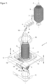
- a device 1 for producing a thread 2 from a yarn 3 can be seen, which in technical terminology is also referred to as a ring spinning machine 1.
- the yarn 3 as a starting material has a very frayed surface structure that is not suitable for further processing in the textile industry.
- the ring spinning machine 1 is therefore used to produce the thread 2 from the yarn 3 with a surface structure that is as homogeneous or smooth as possible.
- the yarn 3 is stored as a continuous web in a storage container 4 that can be transported to the ring spinning machine 1.
- the ring spinning machine 1 conveys the yarn 3 from the storage container 4 and the surface structure of the yarn 3 is homogenized or smoothed by twisting.
- both the guide device 5 and the ring 14 form a type of hinge or swivel joint around which the yarn 3 is twisted or rotated.
- the end of the thread 2 is connected to the rotationally symmetrical body 6 at a fastening point 12.
- the body 6 is set in rotation about its longitudinal axis by a drive device 11, for example a V-belt, so that the thread 2 connected to the body 6 is wound on the outer surface of the body 6, which is also referred to as a balloon in technical terminology.
- This winding process therefore exerts a tensile force on the thread 2 and the the yarn 3 connected thereto, whereby the thread 2 and the yarn 3 are pulled out of the storage container 4 towards the body 6.
- the thread 2 is pulled through an annular thread guide 16 for optimized guidance, which is arranged spatially above the body 6.
- a ring flange 7 is used at a distance from the thread guide 16, which has a closed guide track 8 running around the body 6.
- the guide track 8 is spaced from the surface of the rotationally symmetrical body 6.
- a moving element 9 is movably mounted in the guide track 8. The moving element 9 is often referred to in technical terminology as a so-called traveler or runner.
- the movement element 9 is ring-shaped.
- the movement element 9 therefore has an opening 10 through which the thread 2 is guided.
- the movement element 9 is arranged at the same level as a fastening point 12, so that the first winding of the thread 2 on the body 6 runs in this plane.
- the ring flange 7 and thus the movement element 9 can be moved in the direction of the thread guide 16, so that the subsequent windings of the thread 2 are defined on the entire surface of the body 6.
- the rotation of the body 6 and the associated rotational movement of the thread 2 results in a force exerted by the thread 2 on the moving element 9, which causes the moving element 9 to rotate in the guide track 8 about the longitudinal axis of the body 6.
- Reverse winding of the thread 2 is possible by driving the moving element 9 in the guide track 8, for example magnetically or inductively, and by keeping the body 6 stationary.
- the thread 2 is thus wound around the outer surface of the body 6 by the moving element 9.
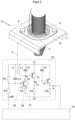
- the rotational movements of the moving element 9 should be measured by at least two coils L1, L2 and an electrical circuit 23 and transmitted to an external electrical device 24 for controlling the coil L1, L2 and for evaluating the rotational movements of the moving element 9.
- the coils L1, L2 each have at least one or a plurality of windings 22, which are powered by the circuit 23 or the external electrical device 24.
- the coils L1, L2 consist of a total of 28 windings 22 to 22 28 and are arranged directly in the vicinity of the movement element 9, namely on the outside of the guide track 8.
- the movement element 9, the material of which is electrically conductive, thus influences the oscillation behavior of the coils L1, L2, namely as soon as the movement element 9 enters or leaves the magnetic field emitted by the coils L1, L2. This is a feedback between the first and second coils L1, L2.
- the circuit 23 essentially consists of an LC oscillator L2, C2, T1 and R3, which are electrically coupled to an inductive feedback K via the first coil L1, a demodulator T2, C3, R4 and an amplifier T3 and R5.
- the electrical components essential to the invention and their interconnection are described in more detail below.
- the electrical component T1 is the first transistor. Its base, collector and detector are identified by the reference numbers 26, 27 and 28.
- L2 and C2 form a parallel resonant circuit, which is excited by the transistor T1, namely at its collector 27.
- the first coil L1 with a coupling capacitor C1 The arrangement of the coils L1 and L2 creates a feedback K depending on the set operating point AP.
- the circuit 23 oscillates.
- the presence of the moving element 9 in the vicinity of the coils L1 and L2 increases this coupling K, so that an amplitude increase according to Figure 3
- the emitter resistor R3 is provided for current negative feedback.
- the high frequency HF is modulated in its amplitude by the feedback K.
- the amplitude modulation is carried out by the moving element 9 and its rotational movements around the longitudinal axis 6'.
- the high frequency HF is therefore modulated by the approach of the moving element 9 in the vicinity of the coils L1, L2.
- the signal heights of the curve NF of the Figure 4 are marked with the reference number 42.
- the demodulator consists of the transistor T2 and the capacitor C3. This connection creates the curve NF, which is shown in Figure 4
- the high frequency HF is no longer part of the curve NF shown there.
- the curve signal NF is amplified by a third transistor T3 in such a way that a higher signal-to-noise ratio is created and the movement element 9 can be further processed into a sensor signal 43 at the output A.
- SNR is an abbreviation for Signal-to-Noise Ratio.
- FIG. 6 The structure of a printed circuit board 33 for the circuit 23 and for the operation of the coils L1, L2 can be seen.
- the components 34 are electrically connected to the coils L1, L2 at a tap 30, which is electrically coupled to the first winding 22 of the coils L1, L2.
- the printed circuit board 33 has a large number of conductor tracks 34 which run in different levels arranged one above the other to save space. It is possible to arrange further electrical components, for example the transistor and coil resistors forming the demodulator, in the different levels of the printed circuit board 33.
- the printed circuit board 33 therefore forms a relevant component with the coils L1, L2, so that the distance between the coils L1, L2 and the electrical components measuring and amplifying the amplitude changes are arranged as close as possible to one another.
- the operating point AP can be programmed and thus controlled. These programming options are available via a known analog controller - as is the case with regard to Figure 6 explained - with an operational amplifier 35 as a control element and low-pass filter 36.
- the optimal operating point AP can be programmed and thus set using a predetermined direct voltage as a reference variable.
- the low-pass filter 36 is required because only a direct voltage without influences from the electrical circuit 23 is necessary to control the operating point AP.
- FIG 8 A partially digitalized workstation controller and its signal acquisition are shown as a circuit diagram.
- the DC voltage component is used as output signal A - as shown in Figure 5 shown - is filtered out with a low-pass filter 36 and the direct voltage is sampled with an A/D converter 37 in a microcontroller 31.
- the voltage of a D/A output of the microcontroller 31, which is connected to the workstation control AP of the circuit 23, is varied.
- the variation of the voltage of the D/A output is stopped.
- the circuit 23 is thus calibrated.
- the DC component of the circuit signal A according to Figure 5 is suppressed with a high-pass filter 38 and a hardware interrupt 39 is triggered with the pulses caused by the moving element 9.
- a hardware interrupt 39 the counter reading of a measuring element 40 is read with the help of suitable algorithms in the microcontroller 31, which is assigned to the external electrical device 24, and the measuring element 40 is then reset to zero.
- the speed or the number of revolutions per minute of the moving element 9 in the guide track 8 can be calculated by a further algorithm.
- Out of Figure 9 is a circuit diagram for the fully digitalized work desk control and its signal acquisition via DSP.
- one of the specific microcontrollers 31 integrated digital signal processing DSP can also be used.
- the output signal A of the circuit 23 is in accordance with Figure 5 without any preceding analog filtering directly with the A/D converter 37.
- the DC voltage component of the circuit signal A is calculated according to Figure 5 calculable.
- the voltage at the output of a D/A converter is changed, to which the operating point control AP of the circuit 23 is connected. As soon as a certain calculated limit value or DC voltage value is reached, the variation of the voltage is stopped.
- the circuit 23 is calibrated.
- the software used is then used to switch the low-pass filtering to high-pass filtering, thereby suppressing the DC voltage components.
- the algorithm used therefore supplies the recorded signal of the moving element 9, which can then be further evaluated using the software used to determine the speed and rotational speed of the moving element 9. For example, this method can also be used to calculate conclusions about the position or current state of the moving element 9 in the guideway 8 based on the curve shape using artificial intelligence.
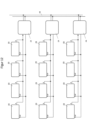
- the control for all circuits 23 used can be combined on the motherboard 33.
- the microcontroller 31 can be connected to the microcontroller 31 and can be controlled by it. All circuits 23 connected to the motherboard 33 can be calibrated one after the other using the time slot method, as shown in the Figures 7 to 9 Because of the open collector output of the circuits 23, all outputs can be connected to a common A/D converter 37.
- FIG 11 A BUS interface for the circuit 23 is visible, as is the case for example in Figure 12 is shown as an example. If the individual circuits 23, for example eight of them, are constructed with different graduated voltage dividers R1/R2, each of the circuits 23 has a different operating point AP. This means that several circuits 23 and only two lines can be operated. This measure saves costs and the circuits 23 can be installed with less effort. A type of rail system with two interface conductors A and AP is thus possible, whereby the voltage supply "+" can also be integrated into this line system.
- the ring flange 7 can be used as a common ground minus.
- the microcontroller 31 is connected to an industrial interface. This is indicated with the reference number 44.
- the circuit 23 can be connected to a network and/or to a cloud. The data from each ring spinning station 17 are therefore evaluated together and can be compared with other machine data or with each other.
Landscapes
- Engineering & Computer Science (AREA)
- Physics & Mathematics (AREA)
- General Physics & Mathematics (AREA)
- Textile Engineering (AREA)
- Remote Sensing (AREA)
- Life Sciences & Earth Sciences (AREA)
- Mechanical Engineering (AREA)
- Geology (AREA)
- General Life Sciences & Earth Sciences (AREA)
- Geophysics (AREA)
- Environmental & Geological Engineering (AREA)
- Electromagnetism (AREA)
- Spinning Or Twisting Of Yarns (AREA)
- Filamentary Materials, Packages, And Safety Devices Therefor (AREA)
- Yarns And Mechanical Finishing Of Yarns Or Ropes (AREA)
Description
- Die Erfindung bezieht sich auf eine Ringspinnmaschine mit einer Vorrichtung zur Herstellung eines Fadens aus einem Garn nach dem Oberbegriff des Patentanspruches 1.
- Eine solche Ringspinnmaschine ist aus der
CN 207 244 082 U vorbekannt. Ebenfalls ist auf dieCH 556 923 - Durch die
EP 2 826 899 B1 ist eine weitere Ringspinnmaschine mit einer Ringbank bekannt geworden, an der Spinnringe angeordnet sind. Die Spinnringe bilden mit dem Bewegungselement eine Ringspinnstelle, an der aus einem Garn ein Faden hergestellt und mit einem rotationssymmetrischen Körper verbunden ist. Der rotationssymmetrische Körper ist beispielsweise über einen Riemenantrieb um die eigene Längsachse in Rotation versetzt, sodass der Faden auf dem Körper aufgewickelt ist. Die jeweiligen Bewegungselemente in Form der Spinnringe rotieren dabei um die Längsachse des Körpers, sodass sich die Fäden gegenseitig nicht behindern. Das Bewegungselement ist folglich von dem Faden bewegt und damit in Rotation versetzt. - Die Rotationen der Bewegungselemente sind permanent zu überwachen, um gegebenenfalls Störungen frühzeitig zu erkennen und die Ringspinnmaschine abzuschalten, bevor eine komplexe Verknotung der jeweiligen Fäden entsteht. Mithilfe eines Mikrofons ist dabei die Rotation des Betätigungselementes festgestellt. Durch das Mikrofon werden elektrische Signale beim Durchlaufen des Bewegungselementes generiert, die an eine Platine weitergeleitet sind. An der Platine sind visuelle Anzeigemittel derart positioniert, dass diese von außen erkennbar sind.
- Eine Art der Metalldetektion ist durch die
EP 0 816 870 B1 bekannt geworden. Durch diesen Metalldetektor sollen Metalle in Böden, Wänden oder dgl. erfasst sein. Dabei handelt es sich um die stationäre oder örtliche Bestimmung von Leitungen in Hauswänden bzw. von Metallen im Untergrund. Ein Oszillator generiert dazu sinusförmige Wechselfelder, die in den vorhandenen hinteren Bereich ausgestrahlt werden, durch die ein metallischer Gegenstand geführt ist. Durch das Eintauchen des Gegenstandes aus einem elektrisch leitfähigen Werkstoff verändern sich die Magnetfelder. Solche Veränderungen der Magnetfelder sind messbar und können demnach ausgewertet werden. - Bei beiden bekannt gewordenen Vorrichtungen bzw. Verfahren für den Betrieb eines Metalldetektors hat sich nachteiliger Weise herausgestellt, dass diese zum einen einen sehr komplexen konstruktiven Aufbau aufweisen und zum anderen in ihrer jeweiligen Herstellung sehr kostenintensiv sind, da eine Vielzahl von hochwertigen elektronischen Komponenten zu verwenden sind.
- Es ist daher Aufgabe der Erfindung, eine Ringspinnmaschine mit einer Vorrichtung der Eingangs genannten
- Gattungen derart weiterzubilden, dass diese sowohl zuverlässig und langfristig störungsfrei arbeitet und zudem in der Herstellung wesentlich günstiger zu bauen ist als die bekannt gewordenen Vorrichtungen.
- Diese Aufgabe ist erfindungsgemäß durch die Merkmale des kennzeichnenden Teils von Patentanspruch 1 gelöst.
- Eine weitere vorteilhafte Weiterbildung der Erfindung ergibt sich aus dem Unteranspruch.
- Dadurch, dass an dem Ringflansch mindestens zwei bestimmte Spulen mit jeweils mindestens zwei Wicklungen angeordnet sind, dass die Spulen mit einem elektrischen Schaltkreis gekoppelt sind, durch den die Spulen mit einer konstanten Frequenz angeregt sind, und dass das Bewegungselement aus einem elektrisch leitfähigen Werkstoff hergestellt ist und im Bereich der Spulen eine Amplitudenveränderung bewerkstelligt, die in dem elektrischen Schaltkreis ausgewertet und an ein externes elektrisches Gerät weitergeleitet ist, entstehen permanente Messungen, durch die die Bewegungen oder Rotationen des Bewegungselementes zuverlässig erfasst sind und durch die möglicherweise auftretenden Veränderungen der Umgebungstemperatur, der Luftfeuchtigkeit oder sonstige Umwelteinflüsse, durch die das Schwingverhalten der Spule beeinflusst ist, unverzüglich mittels des elektrischen Schaltkreises bzw. des externen elektrischen Gerätes kompensiert sind.
- Die verwendeten elektrischen Komponenten sind als Standardmassenware kostengünstig zu erwerben, sodass der derart gebildete Schaltkreis mit geringen Betriebsmitteln gebaut werden kann. Die Herstellungskosten zur Auswertung des Rotationsverhaltens des Bewegungselementes sind daher äußerst gering gehalten.
- Zudem können die bereits bestehenden Ringspinnmaschinen mit solchen Spulen und Schaltkreisen nachträglich ausgestattet werden, da diese als nachrüstbarer Bausatz zur Verfügung gestellt werden kann.
- Ferner liefert der elektrische Schaltkreis eindeutige Meßsignale, um Störungen im Betriebsablauf der Ringspinnmaschine zu erkennen und diese durch frühzeitige Eingriffsmöglichkeiten möglichst gering zu halten.
- In der Zeichnung ist ein erfindungsgemäßes Ausführungsbeispiel dargestellt, dass nachfolgend näher erläutert ist. Im Einzelnen zeigt:
- Figur 1
- einen schematischen konstruktiven Aufbau einer Ringspinnmaschine, durch die aus einem aufgefaserten Garn ein Faden hergestellt ist, mit einem das Garn aufnehmenden Vorratsbehälter, mit einer dem Vorratsbehälter nachgeordneten Führungseinrichtung, durch die das Garn in Richtung der Ringspinnmaschine ausgerichtet ist, mit einem rotationssymmetrischen Körper auf den der Faden aufgewickelt ist, und mit einer Antriebseinrichtung, durch die der Körper um die eigene Längsachse rotierend angetrieben ist,
- Figur 2
- ein vergrößerter Ausschnitt der Ringspinnmaschine gemäß
Figur 1 , dem ein Ringflansch zugeordnet ist, der den rotationssymmetrischen Körper ummantelt und in den eine Führungsbahn eingearbeitet ist, in die ein Bewegungselement, in dem eine Öffnung zur Aufnahme des Fadens vorgesehen ist, beweglich gelagert ist, und mit zwei an der Außenseite der Führungsbahn vorgesehenen Spulen, die über eine elektrische Kopplung mit einem Schaltkreis elektrisch gekoppelt ist, durch den die Spulen mit einer konstanten Frequenz angeregt sind, - Figur 3
- ein Spannung-Zeit-Diagramm, durch das eine Amplitudenerhöhung dargestellt ist, während das Bewegungselement gemäß
Figuren 1 und2 im Bereich der Spule vorbeiläuft, - Figur 4
- ein Spannung-Zeit-Diagramm basierend auf den Spannungsverläufen gemäß
Figur 3 mit einer unterdrückten Hochfrequenz, - Figur 5
- ein Spannung-Zeit-Diagramm ausgehend von der Spannung gemäß
Figur 4 nach dessen Verstärkung, - Figur 6
- ein konstruktiver Aufbau einer Leiterplatte als Bestandteil des elektrischen Schaltkreises gemäß den
Figuren 1 und2 , - Figur 7
- eine erste Ausführungsvariante für einen analog arbeitenden Arbeitspunktregler als Bestandteil der elektrischen Schaltung gemäß den
Figuren 1 und2 , - Figur 8
- eine zweite Ausführungsvariante eines teil-digitalisierten Arbeitspunktreglers und Signalerfassung für den Schaltkreis gemäß den
Figuren 1 und2 - Figur 9
- eine dritte Ausführungsvariante eines voll-digitalisierten Arbeitspunktreglers. und der Signalerfassung für den Schaltkreis gemäß den
Figuren 1 und2 , - Figur 10
- ein konstruktiver Aufbau eines Motherboards als Bestandteil der elektrischen Schaltung gemäß den
Figuren 1 und2 für den Betrieb mehrerer Spulen, - Figur 11
- einen schematischen Aufbau einer Schnittstelle für den Betrieb mehrerer Spulen durch den elektrischen Schaltkreis gemäß den
Figuren 1 und2 , ausgeführt als Bus-System und - Figur 12
- die Zusammenschaltung von mehreren Schaltkreisen gemäß
Figur 11 mit einer Schnittstelle an einem Motherboard. - In den
Figuren 1 und2 ist eine Vorrichtung 1 zur Herstellung eines Fadens 2 aus einem Garn 3 zu entnehmen, die in der Fachterminologie auch als Ringspinnmaschine 1 bezeichnet ist. - Das Garn 3 weist als Ausgangsmaterial eine sehr aufgefaserte Oberflächenstruktur auf, die für weitere Bearbeitungsprozesse in der Textilindustrie nicht geeignet ist. Die Ringspinnmaschine 1 dient daher dazu, aus dem Garn 3 den Faden 2 mit einer möglichst homogenen oder glatten Oberflächenstruktur herzustellen. Zu diesem Zweck ist das Garn 3 als Endlosbahn in einem Vorratsbehälter 4 gelagert, der zu der Ringspinnmaschine 1 transportierbar ist. Durch die Ringspinnmaschine 1 wird das Garn 3 aus dem Vorratsbehälter 4 gefördert und durch Verdrillen ist die Oberflächenstruktur des Garnes 3 homogenisiert oder geglättet.
- Dies ist dadurch bewerkstelligt, dass das Garn 3 zunächst von einer Führungsnut-Einrichtung 5 aufgenommen und in Richtung eines rotationssymmetrischen Körpers 6 transportiert ist. Um das Garn 3 optimal auszurichten, sind zum einen in der Führungseinrichtung 5 ein Spinndreieck 13 als Garnführung und räumlich nachfolgend zu dieser ein Ring 15 vorgesehen. Das Garn 3 ist durch den Ring 14 geführt. Somit bildet sowohl die Führungseinrichtung 5 als auch den Ring 14 eine Art Scharnier oder Drehgelenk, um das das Garn 3 gedrillt oder rotiert ist.
- Das Ende des Fadens 2 ist an einer Befestigungsstelle 12 mit dem rotationssymmetrischen Körper 6 verbunden. Durch eine Antriebseinrichtung 11, beispielsweise ein Keilriemen, ist der Körper 6 um seine Längsachse in Rotation versetzt, sodass der mit dem Körper 6 verbundene Faden 2 auf der Mantelfläche des Körpers 6 der in der Fachterminologie auch als Ballon bezeichnet ist, aufgewickelt ist. Durch diesen Wickelprozess wirkt demnach eine Zugkraft auf den Faden 2 und das mit diesem verbundene Garn 3 ein, wodurch der Faden 2 und das Garn 3 aus dem Vorratsbehälter 4 in Richtung des Körpers 6 gezogen ist.
- Um den Faden 2 nach Verlassen des Ringes 15 zu verdrillen und damit die möglichst homogene Oberflächenstruktur zu schaffen, ist der Faden 2 zur optimierten Führung durch eine ringförmige Fadenführung 16 gezogen, die räumlich gesehen oberhalb des Körpers 6 angeordnet ist. Beabstandet zu der Fadenführung 16 ist ein Ringflansch 7 zu verwenden, der eine um den Körper 6 umlaufende geschlossene Führungsbahn 8 aufweist. Die Führungsbahn 8 ist zu der Oberfläche des rotationssymmetrischen Körpers 6 beabstandet. In die Führungsbahn 8 ist ein Bewegungselement 9 beweglich gelagert eingesetzt. Das Bewegungselement 9 wird in der Fachterminologie oftmals auch als sogenannter Traveller oder Läufer bezeichnet.
- In den gezeigten Ausführungsbeispielen ist das Bewegungselement 9 ringförmig ausgestaltet. Das Bewegungselement 9 weist demnach eine Öffnung 10 auf, durch die der Faden 2 geführt ist. Das Bewegungselement 9 ist im Ausgangszustand der Ringspinnmaschine auf dem identischen Niveau einer Befestigungsstelle 12 angeordnet, sodass die erste Wicklung des Fadens 2 auf dem Körper 6 in dieser Ebene verläuft. Sobald eine bestimmte Anzahl von Wicklungen auf dem Körper 6 erreicht ist, kann der Ringflansch 7 und damit das Bewegungselement 9 in Richtung der Fadenführung 16 verfahren werden, sodass sich die jeweils nachfolgenden Wicklungen des Fadens 2 auf der gesamten Oberfläche des Körpers 6 definiert ergeben.
- Durch die Rotation des Körpers 6 und der damit verbundenen Rotationsbewegung des Fadens 2 entsteht eine von dem Faden 2 auf das Bewegungselement 9 ausgeübte Kraft, durch die das Bewegungselement 9 in der Führungsbahn 8 um die Längsachse des Körpers 6 in Rotation versetzt ist. Eine umgekehrte Aufwicklung des Fadens 2 ist dadurch möglich, dass das Bewegungselement 9 in der Führungsbahn 8 angetrieben ist, beispielsweise magnetisch oder induktiv, und der Körper 6 feststeht. Der Faden 2 ist somit durch das Bewegungselement 9 um die Mantelfläche des Körpers 6 gewickelt.
- Die Rotationsbewegungen des Bewegungselementes 9 sollen durch mindestens zwei Spulen L1, L2 und einem elektrischen Schaltkreis 23 gemessen und an ein externes elektrisches Gerät 24 zur Steuerung der Spule L1, L2 und zur Auswertung der Rotationsbewegungen des Bewegungselementes 9 weitergeleitet sein.
- Die Spulen L1, L2 weisen jeweils mindestens eine oder eine Vielzahl von Wicklungen 22 auf, welche von dem Schaltkreis 23 bzw. dem elektrischen externen Gerät 24 bestromt sind. Im gezeigten Ausführungsbeispiel bestehen die Spulen L1, L2 aus insgesamt 28 Wicklungen 22 bis 2228 und sind unmittelbar im Nahbereich des Bewegungselementes 9, nämlich auf der Außenseite der Führungsbahn 8 angeordnet. Somit beeinflusst das Bewegungselement 9, dessen Werkstoff elektrisch leitfähig ist, das Schwingverhalten der Spulen L1, L2, und zwar sobald das Bewegungselement 9 in das von den Spulen L1, L2 abgestrahlte Magnetfeld eintritt bzw. dieses verlässt. Hierbei handelt es sich um eine Rückkopplung zwischen der ersten und zweiten Spule L1, L2.
- Insbesondere aus
Figur 2 ist ersichtlich, wie der elektrische Schaltkreis 23 aufgebaut ist bzw. aus welchen elektrischen Komponenten dieser gebildet ist und wie diese Komponenten zur Auswertung der Amplitudenveränderungen an den Spulen L1, L2, die als Sensor anzusehen sind, zu deren Kalibrierung und permanenter Einstellung zusammengeschaltet sind. - Im Wesentlichen besteht der Schaltkreis 23 aus einem LC-Oszillator L2, C2, T1 sowie R3, die mit einer induktiven Rückkopplung K über die erste Spule L1, einem Demodulator T2, C3, R4 und einem Verstärker T3 und R5 elektrisch gekoppelt sind. Die erfindungswesentlichen elektrischen Komponenten und deren Zusammenschaltung sind nachfolgend detaillierter beschrieben. Bei der elektrischen Komponente T1 handelt es sich um den ersten Transistor. Dessen Basis, Kollektor und Ermittler sind mit den Bezugsziffern 26, 27 und 28 gekennzeichnet.
- In dem Schaltkreis 23 der
Figur 2 bilden L2 und C2 einen Parallelschwingkreis, der vom Transistor T1, und zwar an dessen Kollektor 27 angeregt ist. Zwischen der Spannungsversorgung, die symbolisch mit einem + gekennzeichnet ist, und der Basis 26 des Transistors T1 sind die erste Spule L1 mit einem Koppelkondensator C1 angeordnet. Durch die Anordnung der Spulen L1 und L2 entsteht eine Rückkopplung K in Abhängigkeit des eingestellten Arbeitspunktes AP. Der Schaltkreis 23 schwingt. Die Präsenz des Bewegungselementes 9 im Nahbereich der Spulen L1 und L2 erhöhen demnach diese Kopplung K, sodass es zu einer Amplituden-Überhöhung gemäßFigur 3 kommt. Zur Stabilisierung des Oszillatorschaltungsteils ist der im Emitterwiderstand R3 zur Stromgegenkopplung vorgesehen. - Bei einer derartigen Amplitudenmodulation ist die Hochfrequenz HF durch die Rückkopplung K in ihrer Amplitude moduliert. Bei diesen erfindungsgemäßen Schaltkreis 23 erfolgt die Amplitudenmodulation durch das Bewegungselement 9 und dessen Rotationsbewegungen um die Längsachse 6'. Durch die Annäherung des Bewegungselementes 9 im Nahbereich der Spulen L1, L2 ist demnach die Hochfrequenz HF moduliert. Die Signalhöhen der Kurve NF der
Figur 4 sind mit der Bezugsziffer 42 gekennzeichnet. Der Demodulator besteht aus dem Transistor T2 und dem Kondensator C3. Durch diese Zusammenschaltung entsteht die Kurve NF, die inFigur 4 dargestellt ist. Dabei ist die Hochfrequenz HF nicht mehr Bestandteil der dort abgebildeten Kurve NF. - Ausgehend von dem in
Figur 4 abgebildeten Kurvenverlauf NF ist durch einen dritten Transistor T3 das Kurven-Signal NF derart verstärkt, dass ein höheres Signal-Rauschverhältnis entsteht und das Bewegungselement 9 in ein Sensorsignal 43 am Ausgang A weiterverarbeitet werden kann. Dies ist schematisch inFigur 5 abgebildet. Dabei bezieht sich SNR als Abkürzung auf Signal-to-Noise Ratio. - In
Figur 6 ist der Aufbau einer Leiterplatte 33 für den Schaltkreis 23 und für den Betrieb der Spulen L1, L2 zu entnehmen. An einem Abgriff 30, der mit der ersten Wicklung 22 der Spulen L1, L2 elektrisch gekoppelt ist, sind die Bauteile 34 mit den Spulen L1, L2 elektrisch verbunden. Die Leiterplatte 33 weist eine Vielzahl von Leiterbahnen 34 auf die platzsparend in verschiedenen übereinander angeordneten Ebenen verlaufen. Es ist möglich, weitere elektrische Komponenten beispielsweise die den Demodulator bildenden Transistor und Spulenwiderstände in den verschiedenen Ebenen der Leiterplatte 33 anzuordnen. - Der Anfang der jeweiligen Spule L1, L2 ist mit der Bezugsziffer 25 und das Ende mit der Bezugsziffer 25' versehen.
- Die Leiterplatte 33 bildet demnach mit den Spulen L1, L2 ein einschlägiges Bauteil, sodass der Abstand zwischen den Spulen L1, L2 und den die Amplitudenveränderungen messenden und verstärkenden elektrischen Komponenten möglichst mit einem sehr geringen räumlichen Abstand voneinander angeordnet sind.
- Aus
Figur 7 ist die Einstellung eines analogen Arbeitspunktreglers ersichtlich. Über den Eingang AP kann der Arbeitspunkt des Oszillators mithilfe einer Gleichspannung gesteuert sein. Damit ist der Oszillator derart einstellbar, dass sich gerade so eine Rückkopplung einstellt und dieser zu schwingen beginnt, wie dies inFigur 3 abgebildet und erläutert ist. An diesem Arbeitspunkt AP ist der Schaltkreis 23 am empfindlichsten. - Damit der Schaltkreis 23 unabhängig von exakten Abständen, Temperatur- und/oder Luftfeuchtigkeitsveränderungen ist, kann der Arbeitspunkt AP programmiert und somit geregelt sein. Diese Programmiermöglichkeiten sind über einen bekannten analogRegler - wie dies hinsichtlich
Figur 6 erläutert ist - mit einem Operationsverstärker 35 als Regelorgan und Tiefpassfilter 36 durchführbar. Der optimale Arbeitspunkt AP ist über eine vorgegebene Gleichspannung als Führungsgröße programmierbar und somit einstellbar. Der Tiefpassfilter 36 ist erforderlich, da zur Regelung des Arbeitspunktes AP ausschließlich eine Gleichspannung ohne Einflüsse des elektrischen Schaltkreises 23 notwendig ist. - In
Figur 8 ist ein teil-digitalisierter Arbeitspultregler und dessen Signalerfassung als Schaltbild dargestellt. Zur Kalibrierung des Schaltkreises 23 ist der Gleichspannungsanteil als Ausgangssignal A - wie dies inFigur 5 gezeigt ist - mit einem Tiefpassfilter 36 herausgefiltert und die Gleichspannung mit einem A/D-Konverter 37 in einem Mikrocontroller 31 abgetastet. Gleichzeitig ist die Spannung eines D/A-Ausgangs des Mikrocontrollers 31 variiert, der an der Arbeitspultsteuerung AP des Schaltkreises 23 angeschlossen ist. Sobald ein bestimmter Wert am A/D-Konverter 37 erreicht ist, ist der Variationsverlauf der Spannung des D/A-Ausgangs gestoppt. Der Schaltkreis 23 ist somit kalibriert. - Der Gleichspannungsanteil des Schaltkreissignals A gemäß
Figur 5 ist mit einem Hochpassfilter 38 unterdrückt und mit den Impulsen, die von dem Bewegungselement 9 verursacht sind, ein Hardware-Interrupt 39 ausgelöst. Mit jedem Hardware-Interrupt 39 ist mithilfe von geeigneten Algorithmen, die im Mikrocontroller 31, das dem externen elektrischen Gerät 24 zugeordnet ist, der Zählerstand eines Meßorgans 40 abgelesen und das Meßorgan 40 anschließend wiederum auf null zurückgesetzt. Mithilfe des Zählerstandes ist durch einen weiteren Algorithmus die Geschwindigkeit oder die Umdrehungszahl pro Minute des Bewegungselementes 9 in der Führungsbahn 8 berechenbar. - Aus
Figur 9 ist ein Schaltbild zur voll-digitalisierten Arbeitspultregelung und dessen Signalerfassung via DSP zu entnehmen. Als Alternative zur teil-digitalisierten Arbeitspultregulierung erläuterten Kalibrierung des elektrischen Schaltkreises 23 und der Signalerfassung des Bewegungselementes 9 ist ebenso eine der bestimmten Mikrocontroller 31 integrierter digitale Signalverarbeitung DSP verwendbar. Dabei ist das Ausgangssignal A des Schaltkreises 23 gemäßFigur 5 ohne vorgeschaltete Analogfilterung direkt mit dem A/D-Konverter 37 abgetastet. Mittels eines im Mikrocontroller 31 hinterlegten Softwareprogramms als Tiefpassfilter oder auf der Grundlage der mathematischen Mittelwertbildung ist der Gleichspannungsanteil des Schaltkreissignals A gemäßFigur 5 berechenbar. Gleichzeitig ist die Spannung am Ausgang eines D/A-Konverters verändert, an die Arbeitspunktsteuerung AP des Schaltkreises 23 angeschlossen ist. Sobald ein bestimmter berechneter Grenzwert oder Gleichspannungswert erreicht ist, ist der Variationsverlauf der Spannung gestoppt. Der Schaltkreis 23 ist kalibriert. - Anschließend ist mittels der verwendeten Software die Tiefpassfilterung auf Hochpassfilterung umgeschaltet und damit sind die Gleichspannungsanteile unterdrückt. Der verwendete Algorithmus liefert folglich das erfasste Signal des Bewegungselementes 9, das anschließend mithilfe der verwendeten Software weiter ausgewertet werden kann, um Geschwindigkeit und Drehzahl des Bewegungselementes 9 zu ermitteln. Beispielsweise können mit dieser Methode auch anhand der Kurvenform mittels künstlicher Intelligenz Rückschlüsse über die Lage oder den aktuellen Zustand des Bewegungselementes 9 in der Führungsbahn 8 errechnet sein.
- In
Figur 10 ist der konstruktive Aufbau einer Schnittstelle zum Anschluss mehrerer Schaltkreise 23 zu entnehmen. - Da das erfindungsgemäße Schaltkreis-System an der Ringspinnmaschine 1 derart kostengünstig herstellbar sein soll, wie dies nur irgendwie erreichbar ist, sollten die einzelnen Schaltkreise 23 möglichst ohne weitere teure elektronische Komponenten auskommen. Daher kann die Regelung für alle verwendeten Schaltkreise 23 auf dem Motherboard 33 zusammengefasst sein. Zur Regelung des Arbeitspunktes AP und zur Auswertung der Signale sind mehrere Schaltkreise 23 an dem Mikrocontroller 31 anschließbar und können von diesem gesteuert sein. Alle am Motherboard 33 angeschlossenen Schaltkreise 23 können im Zeitschlitz-Verfahren nacheinander kalibriert sein, wie dies in den
Figuren 7 bis 9 erläutert ist. Wegen des Open-Kollektor Ausgangs der Schaltkreise 23 können alle Ausgänge auf einem gemeinsamen A/D-Konverter 37 angeschlossen sein. - Durch
Figur 11 ist eine BUS-Schnittstelle für den Schaltkreis 23 ersichtlich, wie dies beispielsweise inFigur 12 beispielhaft dargestellt ist. Sind nämlich die einzelnen Schaltkreise 23, beispielsweise acht davon, mit unterschiedlichen abgestuften Spannungsteiler R1/R2 aufgebaut, so weist jeder der Schaltkreise 23 einen anderen Arbeitspunkt AP auf. Damit lassen sich folglich mehrere Schaltkreise 23 und lediglich zwei Leitungen betreiben. Diese Maßnahme spart Kosten und die Schaltkreise 23 lassen sich mit geringerem Aufwand montieren. Eine Art Schienensystem mit zwei Schnittstellen-Leitern A und AP sind damit möglich, wobei die Spannungsversorgung "+" ebenfalls in diesem Leitungssystem integrierbar ist. Als gemeinsame Masse minus kann der Ringflansch 7 verwendet sein. - Aus
Figur 12 ist der Mikrocontroller 31 an eine Industrie-Schnittstelle angeschlossen. Dies ist mit der Bezugsziffer 44 gekennzeichnet. Auf diese Weise ist der Schaltkreis 23 an ein Netzwerk und/oder an eine Cloud anschließbar. Die Daten von jeder Ringspinnstelle 17 sind folglich gemeinsam ausgewertet und mit anderen Maschinendaten oder auch miteinander vergleichbar.
Claims (2)
- Ringspinnmaschine (1) zur Herstellung eines Fadens (2) aus einem Garn (3), bestehend aus:- einem das Garn (3) bereitstellenden Vorratsbehälter (4), aus dem das Garn (3) zunächst von einer der Ringspinnmaschine (1) zugeordneten Führungseinrichtung (5) aufgenommen und in Richtung eines zu der Führungseinrichtung (5) beabstandeten rotationssymmetrischen Körpers (6) gefördert ist,- wobei durch die Führungseinrichtung (5) und einen dieser räumlich nachfolgenden Ring (14) eine Art Drehgelenk gebildet ist, um die das Garn (3) zur Erzeugung des Fadens (2) verdrillt ist,- und der aus dem Garn (3) gesponnene Faden (2) auf dem rotationssymmetrischen Körper (6) aufgewickelt ist,- einem den Körper (6) umschließenden und zu diesem beabstandet angeordneten Ringflansch (7), in den eine umlaufende Führungsbahn (8) eingearbeitet ist,- einem in der Führungsbahn (8) des Ringflansches (7) beweglich gelagerten Bewegungselement (9), in dem eine den Faden (2) aufnehmende Öffnung (10) vorgesehen ist,- und aus einer Antriebseinrichtung (11), durch die das Bewegungselement (9) in der Führungsbahn (8) bewegt werden kann, wobeian dem Ringflansch (7) mindestens zwei bestromte Spulen (L1, L2) mit jeweils mindestens einer Wicklung (22, 221, 222 - 22n) auf der Außenseite der Führungsbahn (8) unmittelbar im Nahbereich des Bewegungselementes (9) angeordnet sind, dass die jeweilige Spule (L1, L2) mit einem Schaltkreis (23) elektrisch gekoppelt ist, durch den die jeweilige Spule (L1, L2) mit einer konstanten Frequenz angeregt ist, und dass das Bewegungselement (9) aus einem elektrisch leitfähigen Werkstoff hergestellt ist und im Bereich der Spulen (L1, L2) durch eine Rotation um die Längsachse (6') des rotationssymmetrischen Körpers (6) im Nahbereich der Spulen (L1, L2) eine Amplitudenveränderung bewerkstelligt, die in dem elektrischen Schaltkreis (23) ausgewertet und an ein externes elektrisches Gerät (24) weitergeleitet ist durch das der Schaltkreis (23) mit einer programmierbaren Gleichspannung versorgt ist,dadurch gekennzeichnet,dass der Schaltkreis (23) im Wesentlichen aus einem LC-Oszillator aus einer zweiten Spule (L2), einem zweiten Kondensator (C2), einem ersten Transistor (T1) und einem dritten Widerstand (R3), nämlich einem Emitterwiderstand, besteht,wobei in dem elektrischen Schaltkreis (23) die zweite Spule (L2) und der zweite Kondensator (C2) einen Parallelschwingkreis bilden, welcher von dem ersten Transistor (T1) an dessen Kollektor (27) angeregt ist,wobei zwischen einer Spannungsversorgung (+) und einer Basis (26) des ersten Transistors (T1) eine erste Spule (L1) mit einem Koppelkondensator (C1) angeordnet ist, so dass durch die Anordnung der Spulen (L1, L2) eine Rückkopplung in Abhängigkeit des eingestellten Arbeitspunktes AP entstehtwobei das Bewegungselement (9) als Modulator wirkt und in dem elektrischen Schaltkreis (23) ein Demodulator (T1, T2) in Form eines zweiten Transistors (T2), welcher mit einem dritten Kondensator (C3) und einem vierten Widerstand (R4) beschaltet und mit einem Verstärker aus einem dritten Transistor (T3) und einem fünften Widerstand (R5) elektrisch gekoppelt ist, vorgesehen ist, durch welchen eine Amplitudenveränderung der Spulen (L1, L2) als elektrische Spannung oder Signal festgestellt ist, und wobei jeder der Transistoren (T1, T2, T3) eine Basis (26), einen Kollektor (27) und einen Emitter (28) aufweist..
- Ringspinnmaschine nach Anspruch 1,
dadurch gekennzeichnet,
dass die Basis (26) des Transistors (T1) mit der letzten Wicklung (22n) der Spule (L1, L2) und der Kollektor (27) des Transistors (T2) mit der ersten oder zweiten Wicklung (22 oder 221) der Spule (L1, L2) elektrisch verbunden ist und dass am Emitter (28) des Transistors (T1) ein Widerstand zur Stromgegenkopplung bzw. Schaltungsstabilisierung angeschlossen ist.
Priority Applications (4)
| Application Number | Priority Date | Filing Date | Title |
|---|---|---|---|
| EP20200002.2A EP3978662B1 (de) | 2020-10-05 | 2020-10-05 | Ringspinnmaschine mit einer vorrichtung zur herstellung eines fadens aus einem garn |
| DK20200002.2T DK3978662T3 (da) | 2020-10-05 | 2020-10-05 | Ringspindemaskine med en anordning til fremstilling af en tråd ud fra et garn |
| PL20200002.2T PL3978662T3 (pl) | 2020-10-05 | 2020-10-05 | Pierścieniowa maszyna przędzalnicza z urządzeniem do wytwarzania nitki z przędzy |
| EP23183196.7A EP4245900A3 (de) | 2020-10-05 | 2020-10-05 | Vorrichtung zur herstellung eines fadens aus einem garn |
Applications Claiming Priority (1)
| Application Number | Priority Date | Filing Date | Title |
|---|---|---|---|
| EP20200002.2A EP3978662B1 (de) | 2020-10-05 | 2020-10-05 | Ringspinnmaschine mit einer vorrichtung zur herstellung eines fadens aus einem garn |
Related Child Applications (2)
| Application Number | Title | Priority Date | Filing Date |
|---|---|---|---|
| EP23183196.7A Division-Into EP4245900A3 (de) | 2020-10-05 | 2020-10-05 | Vorrichtung zur herstellung eines fadens aus einem garn |
| EP23183196.7A Division EP4245900A3 (de) | 2020-10-05 | 2020-10-05 | Vorrichtung zur herstellung eines fadens aus einem garn |
Publications (2)
| Publication Number | Publication Date |
|---|---|
| EP3978662A1 EP3978662A1 (de) | 2022-04-06 |
| EP3978662B1 true EP3978662B1 (de) | 2024-12-04 |
Family
ID=73020029
Family Applications (2)
| Application Number | Title | Priority Date | Filing Date |
|---|---|---|---|
| EP20200002.2A Active EP3978662B1 (de) | 2020-10-05 | 2020-10-05 | Ringspinnmaschine mit einer vorrichtung zur herstellung eines fadens aus einem garn |
| EP23183196.7A Withdrawn EP4245900A3 (de) | 2020-10-05 | 2020-10-05 | Vorrichtung zur herstellung eines fadens aus einem garn |
Family Applications After (1)
| Application Number | Title | Priority Date | Filing Date |
|---|---|---|---|
| EP23183196.7A Withdrawn EP4245900A3 (de) | 2020-10-05 | 2020-10-05 | Vorrichtung zur herstellung eines fadens aus einem garn |
Country Status (3)
| Country | Link |
|---|---|
| EP (2) | EP3978662B1 (de) |
| DK (1) | DK3978662T3 (de) |
| PL (1) | PL3978662T3 (de) |
Family Cites Families (11)
| Publication number | Priority date | Publication date | Assignee | Title |
|---|---|---|---|---|
| DE1284989B (de) * | 1967-10-21 | 1968-12-12 | Bosch Gmbh Robert | Elektronischer Naeherungsschalter |
| DE1765593A1 (de) * | 1968-06-14 | 1971-03-04 | Bosch Gmbh Robert | Elektronischer Naehrungsschalter |
| CH556923A (de) * | 1973-04-05 | 1974-12-13 | Zellweger Uster Ag | Verfahren und vorrichtung zur laufenden ueberwachung von verarbeitungsmaschinen der textilindustrie. |
| IT1006331B (it) * | 1974-02-11 | 1976-09-30 | Montefibre Spa | Dispositivo rilevatore di rottura del filo negli stiratori e fila toi |
| DE3716829C2 (de) * | 1986-07-03 | 1994-12-15 | Zinser Textilmaschinen Gmbh | Verfahren und Einrichtung zum Verringern der Ausfallquote von Stoppvorrichtungen an einer Spinnereimaschine |
| DE3708114A1 (de) * | 1987-03-13 | 1988-09-22 | Zinser Textilmaschinen Gmbh | Vorrichtung zum erfassen von betriebszustaenden an arbeitsstellen einer spinnmaschine |
| JPH06248526A (ja) * | 1993-02-22 | 1994-09-06 | Toyota Autom Loom Works Ltd | 紡機の糸切れ検出装置 |
| DE4421912A1 (de) * | 1994-06-24 | 1996-01-11 | Inst Textil & Faserforschung | Verfahren und Vorrichtung zum Zentrieren von Spindeln |
| DE19626363A1 (de) | 1996-07-01 | 1998-01-08 | Klaus Ebinger | Metalldetektor und Verfahren zum Betrieb eines Metalldetektors |
| DE102013011921A1 (de) | 2013-07-17 | 2015-01-22 | Saurer Germany Gmbh & Co. Kg | Ringspinnmaschine mit einem Sensor zur Detektion der Bewegung des Ringläufers |
| CN207244082U (zh) * | 2017-09-11 | 2018-04-17 | 上海兰宝传感科技股份有限公司 | 一种细纱机钢丝圈转速检测装置 |
-
2020
- 2020-10-05 DK DK20200002.2T patent/DK3978662T3/da active
- 2020-10-05 PL PL20200002.2T patent/PL3978662T3/pl unknown
- 2020-10-05 EP EP20200002.2A patent/EP3978662B1/de active Active
- 2020-10-05 EP EP23183196.7A patent/EP4245900A3/de not_active Withdrawn
Also Published As
| Publication number | Publication date |
|---|---|
| EP4245900A3 (de) | 2023-11-22 |
| DK3978662T3 (da) | 2025-01-06 |
| EP4245900A2 (de) | 2023-09-20 |
| EP3978662A1 (de) | 2022-04-06 |
| PL3978662T3 (pl) | 2025-04-28 |
Similar Documents
| Publication | Publication Date | Title |
|---|---|---|
| DE69128939T3 (de) | Aufbau eines fadenwickels | |
| EP2567264A2 (de) | Erfassung eines metallischen oder magnetischen objekts | |
| DE2912712A1 (de) | Messanordnung zum nachweis eines in papier, insbesondere in einem wertschein eingebetteten metallischen fadens | |
| EP2995171B1 (de) | Verfahren und vorrichtung zur bestimmung der oberflächentemperatur eines induktiv beheizten walzenmantels | |
| DE4103933C2 (de) | Verfahren zum Feststellen der Position eines beweglichen Bauteils und Schaltung für einen Positionssensor | |
| DE4402582C2 (de) | Verfahren und Vorrichtung zur Optimierung der Spinngeometrie einer Ringspinnmaschine | |
| CH630667A5 (de) | Schaltungsanordnung an einer einrichtung zur erzeugung eines faserbandes einheitlicher dichte. | |
| DE3708331C1 (de) | Verfahren zur Einstellung des Fadenzugkraftverhaeltnisses zwischen Aussen- und Innenfaden bei der Herstellung von kablierten technischen Garnen sowie Einrichtung zur Durchfuehrung des Verfahrens | |
| EP0658507B1 (de) | Verfahren zum Ermitteln eines Fadenvorrats in einer Fadenspeicher- und -liefervorrichtung, und Fadenspeicher- und -liefervorrichtung | |
| DE69116204T2 (de) | Vorrichtung zur Überwachung der richtigen Verwendung von Garnen an Textilmaschinen, insbesondere an Strickmaschinen | |
| DE19545891A1 (de) | Verfahren zum Überwachen der Abtastverhältnisse beim Steuern einer Fadenliefervorrichtung | |
| EP0388937B1 (de) | Positioniereinrichtung | |
| EP3978662A1 (de) | Vorrichtung zur herstellung eines fadens aus einem garn | |
| DE102017128472B4 (de) | Induktiver Näherungsschalter und Verfahren zum Betreiben eines induktiven Näherungsschalters | |
| DE2432938B2 (de) | Verfahren und vorrichtung zur fadenlaengenmessung in einer textilmaschine mit mehreren wickelstationen | |
| DE2428898C3 (de) | Überwachungsvorrichtung für fehlerhafte Nadeln an Maschinen zur Herstellung von Maschenware | |
| DE102017128471B4 (de) | Induktiver Näherungsschalter und Verfahren zum Betreiben eines induktiven Näherungsschalters | |
| WO2009127667A1 (de) | Verfahren und anordnung zur bestimmung der geschwindigkeit eines laufenden fadens | |
| EP1100987B1 (de) | Stichbildende maschine und verfahren zum erkennen von fehlfunktionen | |
| DE4042162A1 (de) | Magnetfelddetektor | |
| DE102008047336B4 (de) | Verfahren zur berührungslosen Kontrolle der Dicke einer auf ein Garn aufgebrachten Präparationsschicht und Schaltungsanordnung zur Durchführung des Verfahrens | |
| DE112006003235B4 (de) | Spule und Vorrichtung zum Erkennen von Eigenschaften des Spulgutes | |
| DE102019106283A1 (de) | Vorrichtung und Verfahren zur Überwachung der Abwicklung eines Fadens sowie Nähmaschine | |
| DE8900167U1 (de) | Vorrichtung zum Messen der Fadenspannung an Textilmaschinen | |
| DE2344068A1 (de) | Fadenueberwachungsvorrichtung fuer textilmaschinen |
Legal Events
| Date | Code | Title | Description |
|---|---|---|---|
| PUAI | Public reference made under article 153(3) epc to a published international application that has entered the european phase |
Free format text: ORIGINAL CODE: 0009012 |
|
| STAA | Information on the status of an ep patent application or granted ep patent |
Free format text: STATUS: THE APPLICATION HAS BEEN PUBLISHED |
|
| AK | Designated contracting states |
Kind code of ref document: A1 Designated state(s): AL AT BE BG CH CY CZ DE DK EE ES FI FR GB GR HR HU IE IS IT LI LT LU LV MC MK MT NL NO PL PT RO RS SE SI SK SM TR |
|
| STAA | Information on the status of an ep patent application or granted ep patent |
Free format text: STATUS: REQUEST FOR EXAMINATION WAS MADE |
|
| 17P | Request for examination filed |
Effective date: 20220712 |
|
| RBV | Designated contracting states (corrected) |
Designated state(s): AL AT BE BG CH CY CZ DE DK EE ES FI FR GB GR HR HU IE IS IT LI LT LU LV MC MK MT NL NO PL PT RO RS SE SI SK SM TR |
|
| STAA | Information on the status of an ep patent application or granted ep patent |
Free format text: STATUS: EXAMINATION IS IN PROGRESS |
|
| 17Q | First examination report despatched |
Effective date: 20230315 |
|
| GRAP | Despatch of communication of intention to grant a patent |
Free format text: ORIGINAL CODE: EPIDOSNIGR1 |
|
| STAA | Information on the status of an ep patent application or granted ep patent |
Free format text: STATUS: GRANT OF PATENT IS INTENDED |
|
| INTG | Intention to grant announced |
Effective date: 20240523 |
|
| P01 | Opt-out of the competence of the unified patent court (upc) registered |
Free format text: CASE NUMBER: APP_35758/2024 Effective date: 20240614 |
|
| GRAS | Grant fee paid |
Free format text: ORIGINAL CODE: EPIDOSNIGR3 |
|
| GRAA | (expected) grant |
Free format text: ORIGINAL CODE: 0009210 |
|
| STAA | Information on the status of an ep patent application or granted ep patent |
Free format text: STATUS: THE PATENT HAS BEEN GRANTED |
|
| AK | Designated contracting states |
Kind code of ref document: B1 Designated state(s): AL AT BE BG CH CY CZ DE DK EE ES FI FR GB GR HR HU IE IS IT LI LT LU LV MC MK MT NL NO PL PT RO RS SE SI SK SM TR |
|
| REG | Reference to a national code |
Ref country code: CH Ref legal event code: EP |
|
| REG | Reference to a national code |
Ref country code: DE Ref legal event code: R096 Ref document number: 502020009880 Country of ref document: DE |
|
| REG | Reference to a national code |
Ref country code: IE Ref legal event code: FG4D Free format text: LANGUAGE OF EP DOCUMENT: GERMAN |
|
| REG | Reference to a national code |
Ref country code: DK Ref legal event code: T3 Effective date: 20250103 |
|
| REG | Reference to a national code |
Ref country code: NL Ref legal event code: FP |
|
| REG | Reference to a national code |
Ref country code: SE Ref legal event code: TRGR |
|
| REG | Reference to a national code |
Ref country code: LT Ref legal event code: MG9D |
|
| PG25 | Lapsed in a contracting state [announced via postgrant information from national office to epo] |
Ref country code: HR Free format text: LAPSE BECAUSE OF FAILURE TO SUBMIT A TRANSLATION OF THE DESCRIPTION OR TO PAY THE FEE WITHIN THE PRESCRIBED TIME-LIMIT Effective date: 20241204 |
|
| PG25 | Lapsed in a contracting state [announced via postgrant information from national office to epo] |
Ref country code: FI Free format text: LAPSE BECAUSE OF FAILURE TO SUBMIT A TRANSLATION OF THE DESCRIPTION OR TO PAY THE FEE WITHIN THE PRESCRIBED TIME-LIMIT Effective date: 20241204 |
|
| PG25 | Lapsed in a contracting state [announced via postgrant information from national office to epo] |
Ref country code: BG Free format text: LAPSE BECAUSE OF FAILURE TO SUBMIT A TRANSLATION OF THE DESCRIPTION OR TO PAY THE FEE WITHIN THE PRESCRIBED TIME-LIMIT Effective date: 20241204 |
|
| PG25 | Lapsed in a contracting state [announced via postgrant information from national office to epo] |
Ref country code: ES Free format text: LAPSE BECAUSE OF FAILURE TO SUBMIT A TRANSLATION OF THE DESCRIPTION OR TO PAY THE FEE WITHIN THE PRESCRIBED TIME-LIMIT Effective date: 20241204 |
|
| PG25 | Lapsed in a contracting state [announced via postgrant information from national office to epo] |
Ref country code: LV Free format text: LAPSE BECAUSE OF FAILURE TO SUBMIT A TRANSLATION OF THE DESCRIPTION OR TO PAY THE FEE WITHIN THE PRESCRIBED TIME-LIMIT Effective date: 20241204 Ref country code: GR Free format text: LAPSE BECAUSE OF FAILURE TO SUBMIT A TRANSLATION OF THE DESCRIPTION OR TO PAY THE FEE WITHIN THE PRESCRIBED TIME-LIMIT Effective date: 20250305 |
|
| PG25 | Lapsed in a contracting state [announced via postgrant information from national office to epo] |
Ref country code: RS Free format text: LAPSE BECAUSE OF FAILURE TO SUBMIT A TRANSLATION OF THE DESCRIPTION OR TO PAY THE FEE WITHIN THE PRESCRIBED TIME-LIMIT Effective date: 20250304 |
|
| PG25 | Lapsed in a contracting state [announced via postgrant information from national office to epo] |
Ref country code: SM Free format text: LAPSE BECAUSE OF FAILURE TO SUBMIT A TRANSLATION OF THE DESCRIPTION OR TO PAY THE FEE WITHIN THE PRESCRIBED TIME-LIMIT Effective date: 20241204 |
|
| PG25 | Lapsed in a contracting state [announced via postgrant information from national office to epo] |
Ref country code: IS Free format text: LAPSE BECAUSE OF FAILURE TO SUBMIT A TRANSLATION OF THE DESCRIPTION OR TO PAY THE FEE WITHIN THE PRESCRIBED TIME-LIMIT Effective date: 20250404 |
|
| PG25 | Lapsed in a contracting state [announced via postgrant information from national office to epo] |
Ref country code: PT Free format text: LAPSE BECAUSE OF FAILURE TO SUBMIT A TRANSLATION OF THE DESCRIPTION OR TO PAY THE FEE WITHIN THE PRESCRIBED TIME-LIMIT Effective date: 20250404 |
|
| PG25 | Lapsed in a contracting state [announced via postgrant information from national office to epo] |
Ref country code: EE Free format text: LAPSE BECAUSE OF FAILURE TO SUBMIT A TRANSLATION OF THE DESCRIPTION OR TO PAY THE FEE WITHIN THE PRESCRIBED TIME-LIMIT Effective date: 20241204 |
|
| PG25 | Lapsed in a contracting state [announced via postgrant information from national office to epo] |
Ref country code: RO Free format text: LAPSE BECAUSE OF FAILURE TO SUBMIT A TRANSLATION OF THE DESCRIPTION OR TO PAY THE FEE WITHIN THE PRESCRIBED TIME-LIMIT Effective date: 20241204 |
|
| PG25 | Lapsed in a contracting state [announced via postgrant information from national office to epo] |
Ref country code: SK Free format text: LAPSE BECAUSE OF FAILURE TO SUBMIT A TRANSLATION OF THE DESCRIPTION OR TO PAY THE FEE WITHIN THE PRESCRIBED TIME-LIMIT Effective date: 20241204 |
|
| PG25 | Lapsed in a contracting state [announced via postgrant information from national office to epo] |
Ref country code: CZ Free format text: LAPSE BECAUSE OF FAILURE TO SUBMIT A TRANSLATION OF THE DESCRIPTION OR TO PAY THE FEE WITHIN THE PRESCRIBED TIME-LIMIT Effective date: 20241204 |
|
| REG | Reference to a national code |
Ref country code: DE Ref legal event code: R097 Ref document number: 502020009880 Country of ref document: DE |
|
| PLBE | No opposition filed within time limit |
Free format text: ORIGINAL CODE: 0009261 |
|
| STAA | Information on the status of an ep patent application or granted ep patent |
Free format text: STATUS: NO OPPOSITION FILED WITHIN TIME LIMIT |
|
| PGFP | Annual fee paid to national office [announced via postgrant information from national office to epo] |
Ref country code: PL Payment date: 20250924 Year of fee payment: 6 |
|
| REG | Reference to a national code |
Ref country code: CH Ref legal event code: L10 Free format text: ST27 STATUS EVENT CODE: U-0-0-L10-L00 (AS PROVIDED BY THE NATIONAL OFFICE) Effective date: 20251015 |
|
| REG | Reference to a national code |
Ref country code: CH Ref legal event code: U11 Free format text: ST27 STATUS EVENT CODE: U-0-0-U10-U11 (AS PROVIDED BY THE NATIONAL OFFICE) Effective date: 20251101 |
|
| 26N | No opposition filed |
Effective date: 20250905 |
|
| PGFP | Annual fee paid to national office [announced via postgrant information from national office to epo] |
Ref country code: NL Payment date: 20251023 Year of fee payment: 6 |
|
| PGFP | Annual fee paid to national office [announced via postgrant information from national office to epo] |
Ref country code: DE Payment date: 20251020 Year of fee payment: 6 |
|
| PGFP | Annual fee paid to national office [announced via postgrant information from national office to epo] |
Ref country code: GB Payment date: 20251024 Year of fee payment: 6 |
|
| PGFP | Annual fee paid to national office [announced via postgrant information from national office to epo] |
Ref country code: NO Payment date: 20251022 Year of fee payment: 6 |
|
| PGFP | Annual fee paid to national office [announced via postgrant information from national office to epo] |
Ref country code: AT Payment date: 20251021 Year of fee payment: 6 |
|
| PGFP | Annual fee paid to national office [announced via postgrant information from national office to epo] |
Ref country code: DK Payment date: 20251023 Year of fee payment: 6 Ref country code: IT Payment date: 20251031 Year of fee payment: 6 |
|
| PGFP | Annual fee paid to national office [announced via postgrant information from national office to epo] |
Ref country code: BE Payment date: 20251022 Year of fee payment: 6 |
|
| PGFP | Annual fee paid to national office [announced via postgrant information from national office to epo] |
Ref country code: CH Payment date: 20251101 Year of fee payment: 6 Ref country code: SE Payment date: 20251023 Year of fee payment: 6 |