EP3978655A2 - Method for producing layered film structure and piston for internal combustion engine - Google Patents
Method for producing layered film structure and piston for internal combustion engine Download PDFInfo
- Publication number
- EP3978655A2 EP3978655A2 EP21200000.4A EP21200000A EP3978655A2 EP 3978655 A2 EP3978655 A2 EP 3978655A2 EP 21200000 A EP21200000 A EP 21200000A EP 3978655 A2 EP3978655 A2 EP 3978655A2
- Authority
- EP
- European Patent Office
- Prior art keywords
- film structure
- piston
- film
- layered film
- chemical conversion
- Prior art date
- Legal status (The legal status is an assumption and is not a legal conclusion. Google has not performed a legal analysis and makes no representation as to the accuracy of the status listed.)
- Pending
Links
- 238000002485 combustion reaction Methods 0.000 title claims abstract description 49
- 238000004519 manufacturing process Methods 0.000 title claims abstract description 21
- 238000011282 treatment Methods 0.000 claims abstract description 80
- 238000006243 chemical reaction Methods 0.000 claims abstract description 69
- 239000000126 substance Substances 0.000 claims abstract description 62
- 238000007743 anodising Methods 0.000 claims abstract description 44
- 229910045601 alloy Inorganic materials 0.000 claims abstract description 33
- 239000000956 alloy Substances 0.000 claims abstract description 33
- 229910052751 metal Inorganic materials 0.000 claims abstract description 12
- 239000002184 metal Substances 0.000 claims abstract description 12
- 238000005868 electrolysis reaction Methods 0.000 claims description 35
- 229910000838 Al alloy Inorganic materials 0.000 claims description 33
- 230000003746 surface roughness Effects 0.000 claims description 21
- 230000007423 decrease Effects 0.000 claims description 8
- 229910000861 Mg alloy Inorganic materials 0.000 claims description 6
- 230000035484 reaction time Effects 0.000 claims 2
- 229910052782 aluminium Inorganic materials 0.000 description 69
- XAGFODPZIPBFFR-UHFFFAOYSA-N aluminium Chemical compound [Al] XAGFODPZIPBFFR-UHFFFAOYSA-N 0.000 description 69
- 239000000463 material Substances 0.000 description 24
- 238000000034 method Methods 0.000 description 21
- 230000015572 biosynthetic process Effects 0.000 description 16
- XUIMIQQOPSSXEZ-UHFFFAOYSA-N Silicon Chemical compound [Si] XUIMIQQOPSSXEZ-UHFFFAOYSA-N 0.000 description 14
- 238000005299 abrasion Methods 0.000 description 14
- 229910052710 silicon Inorganic materials 0.000 description 14
- 239000010703 silicon Substances 0.000 description 14
- 230000000873 masking effect Effects 0.000 description 13
- 238000004381 surface treatment Methods 0.000 description 12
- 239000007788 liquid Substances 0.000 description 11
- 239000003921 oil Substances 0.000 description 10
- 238000012360 testing method Methods 0.000 description 9
- 230000000052 comparative effect Effects 0.000 description 8
- 238000005566 electron beam evaporation Methods 0.000 description 7
- 239000000446 fuel Substances 0.000 description 7
- QAOWNCQODCNURD-UHFFFAOYSA-N Sulfuric acid Chemical compound OS(O)(=O)=O QAOWNCQODCNURD-UHFFFAOYSA-N 0.000 description 6
- 238000007796 conventional method Methods 0.000 description 5
- 238000005238 degreasing Methods 0.000 description 5
- 239000007789 gas Substances 0.000 description 5
- 239000002245 particle Substances 0.000 description 5
- 239000011347 resin Substances 0.000 description 5
- 229920005989 resin Polymers 0.000 description 5
- 239000003792 electrolyte Substances 0.000 description 4
- 238000001704 evaporation Methods 0.000 description 4
- 230000008020 evaporation Effects 0.000 description 4
- 238000012545 processing Methods 0.000 description 4
- 238000005229 chemical vapour deposition Methods 0.000 description 3
- 230000003750 conditioning effect Effects 0.000 description 3
- 239000013078 crystal Substances 0.000 description 3
- 238000001035 drying Methods 0.000 description 3
- 229920001971 elastomer Polymers 0.000 description 3
- 230000007613 environmental effect Effects 0.000 description 3
- 239000011159 matrix material Substances 0.000 description 3
- 239000013618 particulate matter Substances 0.000 description 3
- 238000005240 physical vapour deposition Methods 0.000 description 3
- 239000005060 rubber Substances 0.000 description 3
- 238000005406 washing Methods 0.000 description 3
- 229920000459 Nitrile rubber Polymers 0.000 description 2
- NBIIXXVUZAFLBC-UHFFFAOYSA-N Phosphoric acid Chemical compound OP(O)(O)=O NBIIXXVUZAFLBC-UHFFFAOYSA-N 0.000 description 2
- PPBRXRYQALVLMV-UHFFFAOYSA-N Styrene Chemical compound C=CC1=CC=CC=C1 PPBRXRYQALVLMV-UHFFFAOYSA-N 0.000 description 2
- RTAQQCXQSZGOHL-UHFFFAOYSA-N Titanium Chemical compound [Ti] RTAQQCXQSZGOHL-UHFFFAOYSA-N 0.000 description 2
- PTFCDOFLOPIGGS-UHFFFAOYSA-N Zinc dication Chemical compound [Zn+2] PTFCDOFLOPIGGS-UHFFFAOYSA-N 0.000 description 2
- 230000003213 activating effect Effects 0.000 description 2
- 230000004913 activation Effects 0.000 description 2
- 230000033228 biological regulation Effects 0.000 description 2
- 239000011575 calcium Substances 0.000 description 2
- 238000005266 casting Methods 0.000 description 2
- 239000011248 coating agent Substances 0.000 description 2
- 238000000576 coating method Methods 0.000 description 2
- 239000000567 combustion gas Substances 0.000 description 2
- 238000001816 cooling Methods 0.000 description 2
- 230000003247 decreasing effect Effects 0.000 description 2
- 238000011156 evaluation Methods 0.000 description 2
- 239000012212 insulator Substances 0.000 description 2
- 238000003754 machining Methods 0.000 description 2
- 239000010705 motor oil Substances 0.000 description 2
- 230000003287 optical effect Effects 0.000 description 2
- 230000001590 oxidative effect Effects 0.000 description 2
- NBIIXXVUZAFLBC-UHFFFAOYSA-K phosphate Chemical compound [O-]P([O-])([O-])=O NBIIXXVUZAFLBC-UHFFFAOYSA-K 0.000 description 2
- 229940085991 phosphate ion Drugs 0.000 description 2
- 229920002379 silicone rubber Polymers 0.000 description 2
- 239000004945 silicone rubber Substances 0.000 description 2
- 239000010936 titanium Substances 0.000 description 2
- 229910052719 titanium Inorganic materials 0.000 description 2
- 238000007740 vapor deposition Methods 0.000 description 2
- LRXTYHSAJDENHV-UHFFFAOYSA-H zinc phosphate Chemical compound [Zn+2].[Zn+2].[Zn+2].[O-]P([O-])([O-])=O.[O-]P([O-])([O-])=O LRXTYHSAJDENHV-UHFFFAOYSA-H 0.000 description 2
- 229910000165 zinc phosphate Inorganic materials 0.000 description 2
- OYPRJOBELJOOCE-UHFFFAOYSA-N Calcium Chemical compound [Ca] OYPRJOBELJOOCE-UHFFFAOYSA-N 0.000 description 1
- OKTJSMMVPCPJKN-UHFFFAOYSA-N Carbon Chemical compound [C] OKTJSMMVPCPJKN-UHFFFAOYSA-N 0.000 description 1
- 244000043261 Hevea brasiliensis Species 0.000 description 1
- FYYHWMGAXLPEAU-UHFFFAOYSA-N Magnesium Chemical compound [Mg] FYYHWMGAXLPEAU-UHFFFAOYSA-N 0.000 description 1
- 239000005062 Polybutadiene Substances 0.000 description 1
- 229920006311 Urethane elastomer Polymers 0.000 description 1
- 229920000800 acrylic rubber Polymers 0.000 description 1
- 239000000654 additive Substances 0.000 description 1
- 230000000996 additive effect Effects 0.000 description 1
- 230000002411 adverse Effects 0.000 description 1
- 229910000147 aluminium phosphate Inorganic materials 0.000 description 1
- 238000002048 anodisation reaction Methods 0.000 description 1
- 229910052791 calcium Inorganic materials 0.000 description 1
- 229910052799 carbon Inorganic materials 0.000 description 1
- 230000015556 catabolic process Effects 0.000 description 1
- 150000001875 compounds Chemical class 0.000 description 1
- 230000006835 compression Effects 0.000 description 1
- 238000007906 compression Methods 0.000 description 1
- 238000006731 degradation reaction Methods 0.000 description 1
- 230000000593 degrading effect Effects 0.000 description 1
- 238000000151 deposition Methods 0.000 description 1
- 230000008021 deposition Effects 0.000 description 1
- 238000013461 design Methods 0.000 description 1
- 230000002542 deteriorative effect Effects 0.000 description 1
- 230000000694 effects Effects 0.000 description 1
- 230000005611 electricity Effects 0.000 description 1
- 239000010419 fine particle Substances 0.000 description 1
- 238000007654 immersion Methods 0.000 description 1
- 239000012535 impurity Substances 0.000 description 1
- 238000002347 injection Methods 0.000 description 1
- 239000007924 injection Substances 0.000 description 1
- 150000002500 ions Chemical class 0.000 description 1
- 238000005461 lubrication Methods 0.000 description 1
- 229910052749 magnesium Inorganic materials 0.000 description 1
- 239000011777 magnesium Substances 0.000 description 1
- 229920003052 natural elastomer Polymers 0.000 description 1
- 229920001194 natural rubber Polymers 0.000 description 1
- 238000000879 optical micrograph Methods 0.000 description 1
- 229920000058 polyacrylate Polymers 0.000 description 1
- 229920002857 polybutadiene Polymers 0.000 description 1
- 230000002265 prevention Effects 0.000 description 1
- 230000001105 regulatory effect Effects 0.000 description 1
- 238000007789 sealing Methods 0.000 description 1
- 239000000243 solution Substances 0.000 description 1
- 238000005507 spraying Methods 0.000 description 1
- 238000007669 thermal treatment Methods 0.000 description 1
- XLYOFNOQVPJJNP-UHFFFAOYSA-N water Substances O XLYOFNOQVPJJNP-UHFFFAOYSA-N 0.000 description 1
Images


Classifications
-
- C—CHEMISTRY; METALLURGY
- C25—ELECTROLYTIC OR ELECTROPHORETIC PROCESSES; APPARATUS THEREFOR
- C25D—PROCESSES FOR THE ELECTROLYTIC OR ELECTROPHORETIC PRODUCTION OF COATINGS; ELECTROFORMING; APPARATUS THEREFOR
- C25D11/00—Electrolytic coating by surface reaction, i.e. forming conversion layers
- C25D11/02—Anodisation
- C25D11/024—Anodisation under pulsed or modulated current or potential
-
- C—CHEMISTRY; METALLURGY
- C25—ELECTROLYTIC OR ELECTROPHORETIC PROCESSES; APPARATUS THEREFOR
- C25D—PROCESSES FOR THE ELECTROLYTIC OR ELECTROPHORETIC PRODUCTION OF COATINGS; ELECTROFORMING; APPARATUS THEREFOR
- C25D11/00—Electrolytic coating by surface reaction, i.e. forming conversion layers
- C25D11/02—Anodisation
- C25D11/04—Anodisation of aluminium or alloys based thereon
-
- C—CHEMISTRY; METALLURGY
- C25—ELECTROLYTIC OR ELECTROPHORETIC PROCESSES; APPARATUS THEREFOR
- C25D—PROCESSES FOR THE ELECTROLYTIC OR ELECTROPHORETIC PRODUCTION OF COATINGS; ELECTROFORMING; APPARATUS THEREFOR
- C25D11/00—Electrolytic coating by surface reaction, i.e. forming conversion layers
- C25D11/02—Anodisation
- C25D11/30—Anodisation of magnesium or alloys based thereon
-
- F—MECHANICAL ENGINEERING; LIGHTING; HEATING; WEAPONS; BLASTING
- F02—COMBUSTION ENGINES; HOT-GAS OR COMBUSTION-PRODUCT ENGINE PLANTS
- F02F—CYLINDERS, PISTONS OR CASINGS, FOR COMBUSTION ENGINES; ARRANGEMENTS OF SEALINGS IN COMBUSTION ENGINES
- F02F3/00—Pistons
Definitions
- the present invention relates to a method for producing a layered film structure and a piston for an internal combustion engine.
- an aluminum alloy used generally as a piston material contains a large amount of silicon to improve castability and abrasion resistance, and has a metal tissue with such silicon crystallized.
- An anodized film is formed by oxidizing aluminum, and therefore, a portion with such silicon precipitated at many sites (or in a large shape) is unlikely to form an anodized film, resulting in an uneven film and increasing surface roughness.
- Patent Literature 1 discloses an anodizing method, which comprises repeating a step of applying a positive voltage to an aluminum alloy part and a step of removing a charge, wherein each period for applying the positive voltage ranges from 25 ⁇ s to 100 ⁇ s, with the purpose of forming a dense anodized film having a uniform thickness on a surface of an aluminum alloy part.
- the present invention has an object of providing a method for producing a layered film structure having an anodized film or a chemical conversion film formed on a surface of an alloy member without being affected by a precipitated phase contained in the alloy member, and a piston for an internal combustion engine having that layered film structure.
- the present invention is, in one aspect, a method for producing a layered film structure, which includes: a step of forming a pure metal layer on a surface of an alloy member, and a step of conducting an anodizing treatment or a chemical conversion treatment on the pure metal layer to obtain a layered film structure having the alloy member and a film formed on the surface thereof.
- the present invention is, in another aspect, a piston for an internal combustion engine having a layered film structure with an alloy member and a film formed on a surface thereof, wherein: (a) an interface between the alloy member and the film in the layered film structure is linear at a cross section of the layered film structure; or (b) a precipitated phase contained in the alloy member is present in the interface between the alloy member and the film in the layered film structure, and the interface is linear at the cross-section of the layered film structure except a portion where the precipitated phase is present.
- the present invention provides a layered film structure having a smooth anodized film or a chemical conversion film formed on a surface of an alloy member without being affected by a precipitated phase contained in the alloy member.
- a surface of a piston for an internal combustion engine, especially a surface of a first ring groove, with a layered film structure having such a smooth surface can reduce a flow rate of blowby gas, and also further suppress rise of oil.
- the entirety of a pure metal layer formed on an alloy member is turned into a surface film by an anodizing treatment or a chemical conversion treatment and no pure metal layer remains below this surface film; and this can prevent occurrence of degrading of mechanical properties (fatigue strength at elevated temperature, tensile strength, proof stress, etc.) in an elevated temperature range.
- This embodiment shows a case for producing a piston for an internal combustion piston having a layered film structure.
- the production method of the present invention is not limited thereto, and it may be applied to a case for producing an alloy member, other than a piston for an internal combustion engine, having an anodized film formed thereon.
- the drawings are not necessarily drawn to scale in order to facilitate of an understanding of the invention.
- the piston 10 for an internal combustion engine has, as a ring groove on an outer periphery, three ring grooves from the side of a piston crown surface 11: a first ring groove 13 (also referred to as a top ring groove), a second ring groove 15, and an oil ring groove 17.
- a portion between the piston crown surface 11 and the first ring groove 13 is referred to as a first land 12
- a portion between the first ring groove 13 and the second ring groove 15 is referred to as a second land 14
- a portion between the second ring groove 15 and the oil ring groove 17 is referred to as a third land 16
- a portion below the oil ring groove 17 is referred to as a skirt portion 18.
- a first ring also referred to as a top ring
- a second ring is inserted into the second ring groove 15
- an oil ring (not shown) is inserted into the oil ring groove 17.
- the piston 10 for an internal combustion engine has a piston pin hole 19 for allowing a piston pin (not shown) to slide.
- the piston 10 for an internal combustion engine is an alloy member formed of an alloy such as an aluminum alloy or a magnesium alloy. These alloys have excellent lightweight properties, strength, mechanical properties (fatigue strength at elevated temperature, tensile strength, proof stress, etc.), and heat resistance.
- An aluminum alloy contains silicon (Si) as a component contributing to abrasion resistance and aluminum adhesion resistance. Examples of these aluminum alloys include AC materials such as AC4, AC8, AC8A, and AC9 series; ADC materials such as ADC10 to ADC14; and A4000 series.
- a magnesium alloy contains aluminum or calcium for the purpose of heat resistance. Examples of these magnesium alloys include a Mg-Al-Ca-based alloy such as ACM522.
- a precipitated phase of silicon or a Ca-Al-based additive is present in a matrix, and it is considered that such a crystallized phase prevents formation of a smooth anodized film or a chemical conversion film.
- a case of an aluminum alloy will be explained; however, the present invention can be applied to other alloys having a metallographic structure with a crystallized phase present in the same manner.
- Portions of the piston 10 for an internal combustion engine in which a layered film structure according to the present invention will be formed include, for example, a piston crown surface 11, piston ring grooves 13, 15, and 17, a skirt portion 18, and a piston pin hole 19.
- a layered film structure is formed on one portion or on several portions thereof.
- the piston crown surface 11 is required to have smoothness. Since it has a lower surface roughness, it provides good flow within a combustion chamber (i.e., it is likely to provide the flow according to design). In particular, in a direct injection engine (an engine of a type which injects a fuel directly into a combustion chamber), lower surface roughness reduces the amount of fuel adhering to a piston, improving fuel efficiency. Since the surface area of the piston crown surface 11 is reduced, cooling loss is decreased.
- the piston ring grooves 13, 15, and 17 are required to have smoothness and abrasion resistance. Since they have lower surface roughness, they enhance an adhesion property with piston rings, thereby reducing blowby gas or rise of oil, improve fuel efficiency, and contribute to compliance with environmental regulations. Combustion gas is sealed to decrease the amount of blowby gas, improving fuel efficiency. In particular, prevention of heat escaping at portions lower than the first ring groove 13 improves fuel efficiency. This is to decrease cooling loss. It is effective that a contact portion with a piston ring has abrasion resistance. In particular, it is effective to provide upper and lower surfaces of the first ring groove with a layered film structure.
- the skirt portion 18 is required to have smoothness and abrasion resistance. Since it has lower surface roughness, it provides good sliding and initial conformability with a cylinder bore (not shown). The abrasion resistance is effective to a sliding portion relative to the cylinder bore.
- the piston pin hole 19 is required to have smoothness and abrasion resistance. Since it has a lower surface roughness, it decreases sliding resistance of a piston pin. The abrasion resistance is effective at a sliding portion relative to the piston pin.
- a method for producing a piston for an internal combustion engine includes a step 21 of casting a piston, a step 22 of thermally treating the casted piston, a step 23 of further machining the thermally treated piston, a step 24 of forming a pure aluminum layer at a portion where a layered film structure is formed, and a step 25 of surface-treating the pure aluminum layer.
- a film is formed by an anodizing treatment or a chemical conversion treatment.
- the method may include a step (not shown) of forming a resin coating on a skirt portion 18.
- the resin coating is, in particular, a resin film having a low coefficient of friction formed on the skirt portion 18, and in recent years, it has been commonly used for pistons for four-wheeled vehicles.
- the step 24 of forming a pure aluminum layer further includes, as shown in Figure 3 , a step 31 of masking a portion where a film will be formed, a step 32 of degreasing a portion exposed by masking, a step 33 of washing the portion with water, a step 34 of drying the portion, a step 36 of forming a pure aluminum layer on the portion, and a step 37 of removing the masking. Note that, if necessary, a step 35 of activating the portion where a film will be formed may be included between the step 34 of drying and the step 36 of forming a pure aluminum layer.
- a circumference of the portion for formation of an anodized film is covered with a masking material.
- a masking material for example, in the case in which a film is to be formed on the piston crown surface 11 and the first ring groove 13, the first land 12 and the second land 14 are covered with the masking material.
- a rubber member is preferably used as the masking material.
- natural rubber, butadiene rubber, styrene rubber, acrylic rubber, urethane rubber, nitrile rubber, silicone rubber or the like may be used.
- an anodizing treatment is conducted in the step of the later surface-treating step 25
- use of nitrile rubber or silicone rubber resistant to a treatment liquid such as sulfuric acid used for the anodizing treatment is preferred, since it enables the anodizing treatment to be conducted with the masking material kept thereon.
- the degreasing step 32, the water-washing step 33, and the drying step 34 are conducted, in this order. These steps are the same as treatments commonly conducted to remove impurities from portions for film formation, and therefore, detailed explanations thereof are omitted.
- the step 36 of forming a pure aluminum layer on a portion for film formation exposed from the masking material is conducted.
- a pure magnesium layer will be formed. That is, a layer of a metal that constitutes a large portion of an alloy for film formation (pure metal layer) is formed.
- a film formation method is, for example, an electron beam evaporation method.
- an electron beam evaporation device 40 is a device in which pure aluminum 43 as a material for evaporation 43 is heated and evaporated by use of an electron gun 42 in a vacuum chamber 41 to generate particles 44 of the material component and the particles are used to form a pure aluminum layer on a portion for film formation of the piston 10 for an internal combustion engine.
- the piston 10 for an internal combustion engine is fixed by a positioning tool 45 and is rotatably mounted in the vacuum chamber 41 by a support stand 47 having a motor 46.
- the piston 10 for an internal combustion engine is covered with the masking material 48 from the second land to the skirt portion thereof.
- Figure 4 shows a case in which a pure aluminum layer is to be formed on the first ring groove 13 of the piston 10 for an internal combustion engine.
- the piston 10 for an internal combustion engine is disposed in such a direction that the first ring groove 13 is directed to the evaporation material 43, the piston 10 for an internal combustion engine is rotated around its own central axis, and thereby, the pure aluminum layer is formed on an inner surface of the first ring groove 13.
- Figure 5 shows a case in which a pure aluminum layer is formed on the piston crown surface 11 of the piston 10 for an internal combustion engine.
- the piston 10 for an internal combustion engine is disposed in a direction such that the piston crown surface 11 is directed to the evaporation material 43, the piston 10 for an internal combustion engine is rotated around its own central axis, and thereby, the pure aluminum layer is formed on a surface of the piston crown surface 11. After the pure aluminum layer is formed, the step 37 of removing the masking is conducted.
- a method for forming a pure aluminum layer is not limited to the above electron beam evaporation method, and a wide range of vapor deposition methods may be adopted.
- a chemical vapor deposition (CVD method) may be used; and a physical vapor deposition (PVD method) other than the above electron beam evaporation method may be used.
- the step 35 of activating a portion for film formation may be conducted before forming a pure aluminum layer.
- a known activation method may be used in accordance with a CVD method or a PVD method to be adopted as the film formation method.
- the step 25 of surface-treating the thus-formed pure aluminum layer will be performed.
- As the surface treatment an anodizing treatment or a chemical conversion treatment is performed. This enables production of a layered film structure in which an anodized film or a chemical conversion film is formed on a surface of an aluminum alloy.
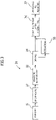
- the anodizing treatment is conducted in an anodizing treatment device 60, for example, as shown in Figure 6 , by oxidizing a surface of the piston for an internal combustion engine by means of: immersing an electrode plate of titanium or carbon as a cathode 63 and the piston for an internal combustion engine as an anode 64 in an electrolyte 62 such as sulfuric acid or phosphoric acid in an electrolytic bath 61; and allowing electricity to flow from a power source 65.
- This forms an anodized film 65 on the surface of the piston for an internal combustion engine as the anode 64.
- an electrolysis method any of direct-current electrolysis, alternating-current electrolysis, alternating current-direct current superimposition electrolysis, etc., may be used.
- Figure 6 shows a case in which the entirety of the piston for an internal combustion engine is immersed in the electrolyte 62 in the electrolytic bath 61; however, the present invention is not limited thereto as long as a portion for film formation of the piston for an internal combustion engine is immersed in the electrolyte 62.
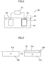
- the relationship between the thickness of the thus-obtained anodized film and the thickness of the pure aluminum layer before surface treatment is explained by using Figure 7 .
- the anodized film is, as described before, an oxide film of aluminum.
- a surface 52s of the anodized film 52 rises by about one-half in thickness of the anodized film 52 from a surface 51a to be treated of a pure aluminum layer 50a before the surface treatment. That is, the surface treatment lowers a surface 51b of the pure aluminum layer 50a (i.e., an interface with the anodized film 52) by about one-half in thickness of the anodized film 52.
- the thickness of the pure aluminum layer 50a is a half or less of the thickness of the anodized film 52, which will be formed.
- the anodized film 52 is to be formed with a thickness of, for example, 20 ⁇ m
- the pure aluminum layer 50a is formed with a thickness of 10 ⁇ m or less
- the entirety of the pure aluminum layer 50a is changed to the anodized film 52 by conducting an anodizing treatment.
- the thickness of the anodized film is, from the viewpoint of the abrasion resistance, preferably in the range of 1 to 60 ⁇ m, and more preferably in the range of 5 to 30 ⁇ m. Accordingly, the thickness of the pure aluminum layer is therefore preferably in the range of 0.5 to 30 ⁇ m, and more preferably in the range of 2.5 to 15 ⁇ m.
- Direct-current electrolysis and alternating current-direct current superimposition electrolysis use different techniques: direct-current electrolysis uses current control, whereas alternating current-direct current superimposition electrolysis uses voltage control.
- direct-current electrolysis uses current control
- alternating current-direct current superimposition electrolysis uses voltage control.
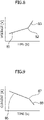
- the value of resistance is increased by growth of the anodized film as the time for anodizing treatment advances; and therefore, when a flow of current is kept constant, a voltage is increased at a constant rate for a section 81 where the anodizing is performed by reaction with the pure aluminum layer. Then, from the time 82 when the anodized film reaches to the aluminum alloy as a base material below the pure aluminum layer, the voltage is abruptly increased by an insulator such as silicon in the base material. In a section 83 where the anodizing is performed by reaction with the aluminum alloy layer, a rate of increase of voltage is higher than that for the above-described section 81.
- a voltage is measured while a current flow is kept constant; and if the anodizing treatment is terminated at the time when a voltage increase rate increases, this enables such a control that the entirety of the pure aluminum layer is changed to the anodized film. Note that after the voltage increase rate increases, the anodizing treatment may be continued.
- the value of resistance is increased by a growth of the anodized film as the time for anodizing treatment proceeds; and therefore, when a voltage is kept constant, a current is decreased at a constant rate for a section 86 where the anodizing is performed by reaction with the pure aluminum layer. Then, from the time 87 when the anodized film reaches the aluminum alloy as a base material below the pure aluminum layer, the current abruptly drops due to an insulator such as silicon in the base material. In a section 88 where the anodizing is performed by reaction with the aluminum alloy layer, a rate of decrease of current is greater than that for the above-described section 86.
- the anodizing treatment by alternating current-direct current superimposition electrolysis, current is measured while voltage is kept constant; and if the anodizing treatment is terminated at the time when a current decrease rate is greater, this enables control such that the entirety of the pure aluminum layer is converted to the anodized film. Note that after the current decrease rate is greater, the anodizing treatment may be continued.
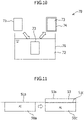
- Chemical conversion treatment is conducted when a chemical conversion device 70 is used, for example, as shown in Figure 10 , by immersing the piston for an internal combustion engine as an object 73 to be treated in a chemical conversion treatment liquid 72 in a treatment bath 71 and causing a chemical reaction. This changes a surface of the object 73 to be treated to a chemical conversion film, so that a film 74 of a compound derived from a material of the object 73 to be treated is formed.
- the chemical conversion treatment liquid 72 include a solution mainly composed of phosphate ion and zinc ion for zinc phosphate treatment.
- Figure 10 shows a case in which the entirety of the piston for an internal combustion engine is immersed in the chemical conversion treatment liquid 72 in the treatment bath 71; however, the present invention is not limited thereto as long as a portion for film formation of the piston for an internal combustion engine is immersed in the chemical conversion treatment liquid 72.
- the chemical conversion treatment is not limited to an immersion method of this type; and for example, spraying of a chemical conversion treatment liquid on the object to be treated enables formation of a chemical conversion film may be formed on a surface thereof.
- the surface treatment lowers a surface 51c of the pure aluminum layer 50a (i.e., an interface with the chemical conversion film 53) by less than one-half in thickness of the chemical conversion film 53.
- the thickness of the pure aluminum layer 50a is less than half the thickness of the anodized film 52 that will be formed.
- the chemical conversion film 53 is to be formed with a thickness of 20 ⁇ m
- the pure aluminum layer 50a is formed with a thickness of less than 10 ⁇ m
- the entirety of the pure aluminum layer 50a is changed to the chemical conversion film 53 by conducting a chemical conversion treatment.
- the thickness of the chemical conversion film is, from the viewpoint of the abrasion resistance, preferably in the range of 1 to 20 ⁇ m, and more preferably in the range of 5 to 15 ⁇ m.
- the thickness of the pure aluminum layer is therefore preferably in the range from less than 0.5 ⁇ m to less than 10 ⁇ m, and more preferably in the range from less than 2.5 ⁇ m to less than 7.5 ⁇ m.
- the chemical conversion treatment is one in which a surface of an object to be treated changes (is changed to) a chemical conversion film, and therefore, time for the entirety of the pure aluminum layer to react with the chemical conversion treatment liquid can be calculated in advance.
- the chemical conversion treatment is terminated at the time when a time to end a reaction with the pure aluminum layer has passed, the entirety of the pure aluminum layer can be changed to the chemical conversion film. Note that after a predetermined time has passed, the chemical conversion treatment may be continued.
- an aluminum alloy 90 is likely to generate unevenness on a surface of an anodized film 94a obtained by an anodizing treatment due to an influence of a precipitated phase of such as silicon in a matrix 91.
- a pure aluminum layer 95 is formed on a surface 93 of an aluminum alloy 90, and thereby, no precipitated phase of such as silicon is present in the pure aluminum layer 95, therefore generating no unevenness on a surface of an anodized films 94b and 94c obtained by an anodizing treatment, so that an extremely smooth anodized films 94b and 94c can be obtained.
- anodized films 94b and 94c can be obtained.
- this anodized film 94c has a structure in which no precipitated phase of, for example, silicon is contained in a top layer portion thereof, whereas a precipitated phase is contained in a deep layer portion (hereinafter, referred to as "precipitated phase-containing anodized film").
- the thickness of the deep layer portion containing a precipitated phase is preferably half or less of the entire film.
- the anodized film is formed in such a manner that its size is increased in a direction toward its surface from the pure aluminum layer as described above; and therefore, when the portion of the deep layer portion containing the precipitated phase becomes large, an adverse influence on the smoothness of the anodized film 94c will be large.
- an interface 93a between the aluminum alloy 90 and the anodized film 94a is uneven in the cross-section of the layered film structure, as shown in Figure 12B , due to the influence of the precipitated phase 92 of, for example, silicon in the aluminum alloy 90.
- an interface 93b between the aluminum alloy 90 and the non-precipitated phase-containing anodized film 94b is linear in the cross-section of the layered film structure as shown in Figure 13B due to the absence of a precipitated phase in the pure aluminum layer 95.
- a precipitated phase 92 is present in an interface 93c between the aluminum alloy 90 and the precipitated phase-containing anodized film 94c in the cross-section of the layered film structure, but the interface 93c is linear except for portions where the precipitated phase 92 is present.
- the layered film structure thus obtained in the present embodiment has a uniform thickness, is dense and hard, and has a smooth surface.
- the anodized film or the chemical conversion film has a surface roughness Ra of preferably 1.3 ⁇ m or less, and more preferably 1.0 ⁇ m or less.
- the index Ra for surface roughness is, as defined in JIS B0601, to represent an arithmetic mean roughness of a contour curve.
- Providing the piston 10 for an internal combustion engine, particularly the first ring groove 13 with such a smooth surface can extremely enhance the airtightness between the first ring groove 13 and the first ring (not shown), and it can reduce an amount of flow of blowby gas leaked from a combustion chamber to a crank chamber via a space between the piston 10 for an internal combustion engine and a cylinder (not shown). In addition, this can suppress rise of oil, thereby keeping PM or PN within desired values.
- the entirety of the pure aluminum layer 95 formed on the aluminum alloy 90 is changed to the anodized film 94 or the chemical conversion film by the anodizing treatment or the chemical conversion treatment, and no pure aluminum layer remains below these films; and this can prevent occurrence of degradation of the mechanical properties (fatigue strength at elevated temperature, tensile strength, proof stress, etc.) in an elevated temperature range.
- a test piece of A1100 material (aluminum purity of 99% or more) was prepared to imitate a pure aluminum layer formed on an aluminum alloy member.
- a surface of the test piece was polished in advance so as to have a surface roughness equivalent to the surface roughness of a piston ring groove (Ra: 0.05 to 0.1 ⁇ m). Then, the surface thereof was anodized.
- the anodizing treatment was conducted using sulfuric acid (5°C) as an electrolyte, and installing a titanium plate as a cathode and the test piece as an anode.
- direct-current electrolysis was constant-current electrolysis with a current density of 12 A/dm 2
- alternating current-direct current electrolysis was a constant-voltage electrolysis with a positive voltage of 30 V, a negative voltage of -2 V, and a frequency of 12 kHz.
- the surface roughness was based on JIS B 0601-2001, in which an arithmetic mean roughness Ra was measured with a measured length of 4 mm and a cut-off of 0.8 mm.
- a test piece was cut and a cross section of a film was measured using an optical microscope.
- the hardness of a film was measured using a micro-Vickers hardness tester from the cross-section of an anodized film.
- An aluminum alloy AC8A material containing 10% or more of silicon was used as a test piece for an anodizing treatment.
- the test piece of a comparative example was polished so as to have a surface roughness equivalent to that of the piston ring groove in the same manner as in the Examples.
- the anodizing treatment was conducted only by alternating current-direct current superimposition electrolysis. Under the same conditions as the Examples, except that the processing time was 40 seconds, and an anodized film was formed on the test piece. The produced anodized film was evaluated in the same manner as the Examples.
- an anodized film with a thickness of about 10 ⁇ m was obtained by either direct-current electrolysis or alternating current-direct current superimposition electrolysis in the Examples.
- the hardness a slight difference is observed depending on the type of electrolysis, but both had a Vickers hardness of 400 HV or more, which is sufficient for the purpose of imparting the abrasion resistance to a piston.
- a surface of the anodized film 94 formed on the test piece 90 made of pure aluminum had a surface roughness Ra of 0.57 ⁇ m in the case of direct-current electrolysis and 0.22 ⁇ m in the case of alternating current-direct current superimposition electrolysis; and an anodized film with an extremely smooth surface profile was produced by alternating current-direct current superimposition electrolysis.
- the Comparative Example had a thickness of about 10 ⁇ m and a Vickers hardness of 393 HV, and it provided an anodized film with almost the same levels of thickness and hardness as Examples while it had a surface roughness Ra of 1.35 ⁇ m, which was significantly greater compared to those of Examples. It is inferred that this is because the surface of the anodized film 94 became uneven due to an influence of a precipitated phase of such as silicon in the aluminum alloy 92, as shown in Figure 14 .
Abstract
Description
- The present invention relates to a method for producing a layered film structure and a piston for an internal combustion engine.
- In recent years, there has been a growing demand to make engines highly efficient or to provide a high compression ratio, and to supercharge engines while complying with environmental regulations, so that engines are increasing in maximum combustion pressure. Under these circumstances, demand for improvement in abrasion resistance a piston ring groove portion (in particular, a top ring groove) is increasing to an extreme degree. As a method for improving abrasion resistance of a ring groove portion, a method for forming an anodized film is known. This is because an anodized film is twice as hard or more than an aluminum alloy as a piston material, and it has an excellent feature in abrasion resistance.
- However, an aluminum alloy used generally as a piston material contains a large amount of silicon to improve castability and abrasion resistance, and has a metal tissue with such silicon crystallized. An anodized film is formed by oxidizing aluminum, and therefore, a portion with such silicon precipitated at many sites (or in a large shape) is unlikely to form an anodized film, resulting in an uneven film and increasing surface roughness.
- This problem occurs not only in aluminum alloys, but also in a member made of an alloy such as a magnesium alloy. In addition, chemical conversion treatment causes a reaction between aluminum and a chemical conversion treatment liquid in the same manner as anodization to form a film, and therefore, a film formed by chemical conversion treatment is also affected by a crystallized phase contained in these alloy members to form an uneven film and increasing surface roughness.
- When surface roughness of a piston surface film, such as an anodized film, is increased, an increase in the flow rate of blowby gas or worsening of fuel efficiency occurs in association with a decrease of combustion gas sealing property. In addition, when a surface roughness of a surface film of a piston is increased, a phenomenon in which an engine oil used for lubrication of engine parts flows into a combustion chamber side (hereinafter, referred to as "rise of oil") occurs. Combustion of an engine oil in a combustion chamber would be a factor in generation of European environmental regulated substances such as particulate matter (PM) or a factor to increase the number thereof such as particle number (PN), and thus, the smoothness of a surface of an anodized film is required.
- Patent Literature 1 discloses an anodizing method, which comprises repeating a step of applying a positive voltage to an aluminum alloy part and a step of removing a charge, wherein each period for applying the positive voltage ranges from 25 µs to 100 µs, with the purpose of forming a dense anodized film having a uniform thickness on a surface of an aluminum alloy part.
- [Patent Literature 1]
JP 2006-083467A - Then, in consideration of the above problems, the present invention has an object of providing a method for producing a layered film structure having an anodized film or a chemical conversion film formed on a surface of an alloy member without being affected by a precipitated phase contained in the alloy member, and a piston for an internal combustion engine having that layered film structure.
- In order to achieve the above purpose, the present invention is, in one aspect, a method for producing a layered film structure, which includes: a step of forming a pure metal layer on a surface of an alloy member, and a step of conducting an anodizing treatment or a chemical conversion treatment on the pure metal layer to obtain a layered film structure having the alloy member and a film formed on the surface thereof.
- In addition, the present invention is, in another aspect, a piston for an internal combustion engine having a layered film structure with an alloy member and a film formed on a surface thereof, wherein: (a) an interface between the alloy member and the film in the layered film structure is linear at a cross section of the layered film structure; or (b) a precipitated phase contained in the alloy member is present in the interface between the alloy member and the film in the layered film structure, and the interface is linear at the cross-section of the layered film structure except a portion where the precipitated phase is present.
- In view of the above, the present invention provides a layered film structure having a smooth anodized film or a chemical conversion film formed on a surface of an alloy member without being affected by a precipitated phase contained in the alloy member. In addition, providing a surface of a piston for an internal combustion engine, especially a surface of a first ring groove, with a layered film structure having such a smooth surface can reduce a flow rate of blowby gas, and also further suppress rise of oil. Furthermore, the entirety of a pure metal layer formed on an alloy member is turned into a surface film by an anodizing treatment or a chemical conversion treatment and no pure metal layer remains below this surface film; and this can prevent occurrence of degrading of mechanical properties (fatigue strength at elevated temperature, tensile strength, proof stress, etc.) in an elevated temperature range.
-
- [
Figure 1] Figure 1 is a front view schematically showing a piston for an internal combustion engine. - [
Figure 2] Figure 2 is a flow chart showing one embodiment of a method for producing a layered film structure according to the present invention. - [
Figure 3] Figure 3 is a flow chart showing further details of a pure aluminum layer film formation step in the method for producing a layered film structure shown inFigure 2 . - [
Figure 4] Figure 4 is a schematic view for explanation of an electron beam evaporation method, which is one example for carrying out the pure aluminum layer film formation step shown inFigure 3 . - [
Figure 5] Figure 5 is a schematic view for explanation of an electron beam evaporation method, which is one example for carrying out the pure aluminum layer film formation step shown inFigure 3 . - [
Figure 6] Figure 6 is a schematic view for explanation of an anodizing treatment as one example for carrying out a surface treatment step in the method for producing a layered film structure shown inFigure 2 . - [
Figure 7] Figure 7 is a side view schematically showing a pure aluminum layer before and after an anodizing treatment. - [
Figure 8] Figure 8 is a graph showing voltage changes relative to processing time in case an anodizing treatment is conducted by direct current electrolysis. - [
Figure 9] Figure 9 is a graph showing current changes relative to processing time in the case that an anodizing treatment is conducted by alternating current-direct current superimposition electrolysis. - [
Figure 10] Figure 10 is a schematic view for explanation of a chemical conversion treatment as one example for carrying out a surface treatment step in the method for producing a layered film structure shown inFigure 2 . - [
Figure 11] Figure 11 is a side view schematically showing a pure aluminum layer before and after a chemical conversion treatment. - [
Figures 12A and 12B] Figures 12A and 12B are cross-sectional views schematically showing a layered film structure obtained by a conventional method. - [
Figures 13A to 13C] Figures 13A to 13C are cross-sectional views schematically showing a layered film structure obtained by the present invention. - [
Figure 14] Figure 14 shows photos taken by an optical microscope, which show cross-sectional views obtained from Examples and a Comparative Example. - Hereinafter, one embodiment for a method for producing a layered film structure and a piston for an internal combustion engine according to the present invention will be described by referring to the accompanying figures. This embodiment shows a case for producing a piston for an internal combustion piston having a layered film structure. However, the production method of the present invention is not limited thereto, and it may be applied to a case for producing an alloy member, other than a piston for an internal combustion engine, having an anodized film formed thereon. In addition, the drawings are not necessarily drawn to scale in order to facilitate of an understanding of the invention.
- First, a piston for an internal combustion engine will be described. As shown in
Figure 1 , thepiston 10 for an internal combustion engine has, as a ring groove on an outer periphery, three ring grooves from the side of a piston crown surface 11: a first ring groove 13 (also referred to as a top ring groove), asecond ring groove 15, and anoil ring groove 17. Regarding the outer periphery, a portion between thepiston crown surface 11 and thefirst ring groove 13 is referred to as afirst land 12, a portion between thefirst ring groove 13 and thesecond ring groove 15 is referred to as asecond land 14, a portion between thesecond ring groove 15 and theoil ring groove 17 is referred to as athird land 16, and a portion below theoil ring groove 17 is referred to as askirt portion 18. A first ring (also referred to as a top ring) (not shown) is inserted into thefirst ring groove 13, a second ring (not shown) is inserted into thesecond ring groove 15, and an oil ring (not shown) is inserted into theoil ring groove 17. In addition, thepiston 10 for an internal combustion engine has apiston pin hole 19 for allowing a piston pin (not shown) to slide. - The
piston 10 for an internal combustion engine is an alloy member formed of an alloy such as an aluminum alloy or a magnesium alloy. These alloys have excellent lightweight properties, strength, mechanical properties (fatigue strength at elevated temperature, tensile strength, proof stress, etc.), and heat resistance. An aluminum alloy contains silicon (Si) as a component contributing to abrasion resistance and aluminum adhesion resistance. Examples of these aluminum alloys include AC materials such as AC4, AC8, AC8A, and AC9 series; ADC materials such as ADC10 to ADC14; and A4000 series. In addition, a magnesium alloy contains aluminum or calcium for the purpose of heat resistance. Examples of these magnesium alloys include a Mg-Al-Ca-based alloy such as ACM522. In a metallographic structure of these alloys, a precipitated phase of silicon or a Ca-Al-based additive is present in a matrix, and it is considered that such a crystallized phase prevents formation of a smooth anodized film or a chemical conversion film. Thus, in the present embodiment, a case of an aluminum alloy will be explained; however, the present invention can be applied to other alloys having a metallographic structure with a crystallized phase present in the same manner. - Portions of the
piston 10 for an internal combustion engine in which a layered film structure according to the present invention will be formed include, for example, apiston crown surface 11,piston ring grooves skirt portion 18, and apiston pin hole 19. Among these, a layered film structure is formed on one portion or on several portions thereof. - The
piston crown surface 11 is required to have smoothness. Since it has a lower surface roughness, it provides good flow within a combustion chamber (i.e., it is likely to provide the flow according to design). In particular, in a direct injection engine (an engine of a type which injects a fuel directly into a combustion chamber), lower surface roughness reduces the amount of fuel adhering to a piston, improving fuel efficiency. Since the surface area of thepiston crown surface 11 is reduced, cooling loss is decreased. - The
piston ring grooves first ring groove 13 improves fuel efficiency. This is to decrease cooling loss. It is effective that a contact portion with a piston ring has abrasion resistance. In particular, it is effective to provide upper and lower surfaces of the first ring groove with a layered film structure. - The
skirt portion 18 is required to have smoothness and abrasion resistance. Since it has lower surface roughness, it provides good sliding and initial conformability with a cylinder bore (not shown). The abrasion resistance is effective to a sliding portion relative to the cylinder bore. - The
piston pin hole 19 is required to have smoothness and abrasion resistance. Since it has a lower surface roughness, it decreases sliding resistance of a piston pin. The abrasion resistance is effective at a sliding portion relative to the piston pin. - Next, a method for producing a piston for an internal combustion engine according to the present embodiment will be described. As shown in
Figure 2 , a method for producing a piston for an internal combustion engine includes astep 21 of casting a piston, astep 22 of thermally treating the casted piston, astep 23 of further machining the thermally treated piston, astep 24 of forming a pure aluminum layer at a portion where a layered film structure is formed, and astep 25 of surface-treating the pure aluminum layer. In the surface-treatingstep 25, a film is formed by an anodizing treatment or a chemical conversion treatment. In addition, if necessary, the method may include a step (not shown) of forming a resin coating on askirt portion 18. The resin coating is, in particular, a resin film having a low coefficient of friction formed on theskirt portion 18, and in recent years, it has been commonly used for pistons for four-wheeled vehicles. - The above respective steps of 21, 22 and 23 of casting, thermal treatment and machining are the same as those used at the time of producing common pistons for an internal combustion engine, and therefore, detailed explanations are omitted.
- The
step 24 of forming a pure aluminum layer further includes, as shown inFigure 3 , astep 31 of masking a portion where a film will be formed, astep 32 of degreasing a portion exposed by masking, astep 33 of washing the portion with water, astep 34 of drying the portion, astep 36 of forming a pure aluminum layer on the portion, and astep 37 of removing the masking. Note that, if necessary, astep 35 of activating the portion where a film will be formed may be included between thestep 34 of drying and thestep 36 of forming a pure aluminum layer. - In the masking
step 31, in order not to form a pure aluminum layer on portions other than portions on which an anodized film is to be formed, a circumference of the portion for formation of an anodized film is covered with a masking material. For example, in the case in which a film is to be formed on thepiston crown surface 11 and thefirst ring groove 13, thefirst land 12 and thesecond land 14 are covered with the masking material. In consideration of productivity, a rubber member is preferably used as the masking material. Regarding the kind of rubber, natural rubber, butadiene rubber, styrene rubber, acrylic rubber, urethane rubber, nitrile rubber, silicone rubber or the like may be used. However, when an anodizing treatment is conducted in the step of the later surface-treatingstep 25, use of nitrile rubber or silicone rubber resistant to a treatment liquid such as sulfuric acid used for the anodizing treatment is preferred, since it enables the anodizing treatment to be conducted with the masking material kept thereon. - After the masking
step 31, the degreasingstep 32, the water-washing step 33, and the dryingstep 34 are conducted, in this order. These steps are the same as treatments commonly conducted to remove impurities from portions for film formation, and therefore, detailed explanations thereof are omitted. - Then, the
step 36 of forming a pure aluminum layer on a portion for film formation exposed from the masking material is conducted. Note that when thepiston 10 for an internal combustion engine is made of a magnesium alloy, a pure magnesium layer will be formed. That is, a layer of a metal that constitutes a large portion of an alloy for film formation (pure metal layer) is formed. A film formation method is, for example, an electron beam evaporation method. As shown inFigures 4 and 5 , an electronbeam evaporation device 40 is a device in whichpure aluminum 43 as a material forevaporation 43 is heated and evaporated by use of anelectron gun 42 in avacuum chamber 41 to generateparticles 44 of the material component and the particles are used to form a pure aluminum layer on a portion for film formation of thepiston 10 for an internal combustion engine. Thepiston 10 for an internal combustion engine is fixed by apositioning tool 45 and is rotatably mounted in thevacuum chamber 41 by asupport stand 47 having amotor 46. Thepiston 10 for an internal combustion engine is covered with the maskingmaterial 48 from the second land to the skirt portion thereof. -
Figure 4 shows a case in which a pure aluminum layer is to be formed on thefirst ring groove 13 of thepiston 10 for an internal combustion engine. Thepiston 10 for an internal combustion engine is disposed in such a direction that thefirst ring groove 13 is directed to theevaporation material 43, thepiston 10 for an internal combustion engine is rotated around its own central axis, and thereby, the pure aluminum layer is formed on an inner surface of thefirst ring groove 13. In addition,Figure 5 shows a case in which a pure aluminum layer is formed on thepiston crown surface 11 of thepiston 10 for an internal combustion engine. Thepiston 10 for an internal combustion engine is disposed in a direction such that thepiston crown surface 11 is directed to theevaporation material 43, thepiston 10 for an internal combustion engine is rotated around its own central axis, and thereby, the pure aluminum layer is formed on a surface of thepiston crown surface 11. After the pure aluminum layer is formed, thestep 37 of removing the masking is conducted. - Note that a method for forming a pure aluminum layer is not limited to the above electron beam evaporation method, and a wide range of vapor deposition methods may be adopted. As the vapor deposition method, a chemical vapor deposition (CVD method) may be used; and a physical vapor deposition (PVD method) other than the above electron beam evaporation method may be used. Note that the
step 35 of activating a portion for film formation may be conducted before forming a pure aluminum layer. As the activation, a known activation method may be used in accordance with a CVD method or a PVD method to be adopted as the film formation method. - The
step 25 of surface-treating the thus-formed pure aluminum layer will be performed. As the surface treatment, an anodizing treatment or a chemical conversion treatment is performed. This enables production of a layered film structure in which an anodized film or a chemical conversion film is formed on a surface of an aluminum alloy. - The anodizing treatment is conducted in an
anodizing treatment device 60, for example, as shown inFigure 6 , by oxidizing a surface of the piston for an internal combustion engine by means of: immersing an electrode plate of titanium or carbon as acathode 63 and the piston for an internal combustion engine as ananode 64 in anelectrolyte 62 such as sulfuric acid or phosphoric acid in anelectrolytic bath 61; and allowing electricity to flow from apower source 65. This forms an anodizedfilm 65 on the surface of the piston for an internal combustion engine as theanode 64. As an electrolysis method, any of direct-current electrolysis, alternating-current electrolysis, alternating current-direct current superimposition electrolysis, etc., may be used. However, in order to obtain a smoother film, it is preferrable to treat by alternating current-direct current superimposition electrolysis. Note thatFigure 6 shows a case in which the entirety of the piston for an internal combustion engine is immersed in theelectrolyte 62 in theelectrolytic bath 61; however, the present invention is not limited thereto as long as a portion for film formation of the piston for an internal combustion engine is immersed in theelectrolyte 62. - The relationship between the thickness of the thus-obtained anodized film and the thickness of the pure aluminum layer before surface treatment is explained by using
Figure 7 . The anodized film is, as described before, an oxide film of aluminum. As shown inFigure 7 , according to the surface treatment, asurface 52s of the anodizedfilm 52 rises by about one-half in thickness of the anodizedfilm 52 from asurface 51a to be treated of apure aluminum layer 50a before the surface treatment. That is, the surface treatment lowers asurface 51b of thepure aluminum layer 50a (i.e., an interface with the anodized film 52) by about one-half in thickness of the anodizedfilm 52. Thus, in order to change the entirety of thepure aluminum layer 50a to the anodizedfilm 52 by conducting the anodizing treatment, the thickness of thepure aluminum layer 50a is a half or less of the thickness of the anodizedfilm 52, which will be formed. - In the case that the anodized
film 52 is to be formed with a thickness of, for example, 20 µm, if thepure aluminum layer 50a is formed with a thickness of 10 µm or less, the entirety of thepure aluminum layer 50a is changed to the anodizedfilm 52 by conducting an anodizing treatment. The thickness of the anodized film is, from the viewpoint of the abrasion resistance, preferably in the range of 1 to 60 µm, and more preferably in the range of 5 to 30 µm. Accordingly, the thickness of the pure aluminum layer is therefore preferably in the range of 0.5 to 30 µm, and more preferably in the range of 2.5 to 15 µm. - Next, a technique for changing the entirety of a pure aluminum layer to an anodized film will be described. Direct-current electrolysis and alternating current-direct current superimposition electrolysis use different techniques: direct-current electrolysis uses current control, whereas alternating current-direct current superimposition electrolysis uses voltage control. Hereinafter, details will be described.
- In direct-current electrolysis, as shown in the graph in
Figure 8 , the value of resistance is increased by growth of the anodized film as the time for anodizing treatment advances; and therefore, when a flow of current is kept constant, a voltage is increased at a constant rate for asection 81 where the anodizing is performed by reaction with the pure aluminum layer. Then, from thetime 82 when the anodized film reaches to the aluminum alloy as a base material below the pure aluminum layer, the voltage is abruptly increased by an insulator such as silicon in the base material. In asection 83 where the anodizing is performed by reaction with the aluminum alloy layer, a rate of increase of voltage is higher than that for the above-describedsection 81. Thus, in the anodizing treatment by direct current electrolysis, a voltage is measured while a current flow is kept constant; and if the anodizing treatment is terminated at the time when a voltage increase rate increases, this enables such a control that the entirety of the pure aluminum layer is changed to the anodized film. Note that after the voltage increase rate increases, the anodizing treatment may be continued. - In alternating current-direct current superimposition electrolysis, as shown in the graph of
Figure 9 , the value of resistance is increased by a growth of the anodized film as the time for anodizing treatment proceeds; and therefore, when a voltage is kept constant, a current is decreased at a constant rate for a section 86 where the anodizing is performed by reaction with the pure aluminum layer. Then, from thetime 87 when the anodized film reaches the aluminum alloy as a base material below the pure aluminum layer, the current abruptly drops due to an insulator such as silicon in the base material. In asection 88 where the anodizing is performed by reaction with the aluminum alloy layer, a rate of decrease of current is greater than that for the above-described section 86. Thus, in the anodizing treatment by alternating current-direct current superimposition electrolysis, current is measured while voltage is kept constant; and if the anodizing treatment is terminated at the time when a current decrease rate is greater, this enables control such that the entirety of the pure aluminum layer is converted to the anodized film. Note that after the current decrease rate is greater, the anodizing treatment may be continued. - Chemical conversion treatment is conducted when a
chemical conversion device 70 is used, for example, as shown inFigure 10 , by immersing the piston for an internal combustion engine as anobject 73 to be treated in a chemicalconversion treatment liquid 72 in atreatment bath 71 and causing a chemical reaction. This changes a surface of theobject 73 to be treated to a chemical conversion film, so that afilm 74 of a compound derived from a material of theobject 73 to be treated is formed. Examples of the chemicalconversion treatment liquid 72 include a solution mainly composed of phosphate ion and zinc ion for zinc phosphate treatment. Note thatFigure 10 shows a case in which the entirety of the piston for an internal combustion engine is immersed in the chemicalconversion treatment liquid 72 in thetreatment bath 71; however, the present invention is not limited thereto as long as a portion for film formation of the piston for an internal combustion engine is immersed in the chemicalconversion treatment liquid 72. In addition, the chemical conversion treatment is not limited to an immersion method of this type; and for example, spraying of a chemical conversion treatment liquid on the object to be treated enables formation of a chemical conversion film may be formed on a surface thereof. - In the chemical conversion treatment, in general, respective steps of degreasing, surface conditioning (deposition of fine particles of crystal), chemical conversion treatment (this treatment), and washing are conducted, in this order. A chemical conversion film allows fine crystal particles in size of about several micrometers to be deposited on a surface. However, in the case in which degreasing is insufficient, surface conditioning is not carried out, or a chemical conversion treatment liquid is degraded, deposited crystal grains may be coarse, deteriorating surface roughness. In order to obtain a smoother film, appropriate management of steps of degreasing or chemical conversion treatment, and introduction of a surface conditioning step are desired.
- The relationship between the thickness of the thus-obtained chemical conversion film and the thickness of the pure aluminum layer before surface treatment is explained with reference to
Figure 11 . In the chemical conversion treatment, ions (for example, phosphate ion or zinc ion, in a zinc phosphate film) necessary for film growth are fed mainly from the chemical conversion treatment liquid. Thus, regarding the thickness of the chemical conversion film, as shown inFigure 11 , according to the surface treatment, asurface 53s of thechemical conversion film 53 rises by more than one-half in thickness of thechemical conversion film 53 from asurface 51a to be treated of thepure aluminum layer 50a before the surface treatment. That is, the surface treatment lowers asurface 51c of thepure aluminum layer 50a (i.e., an interface with the chemical conversion film 53) by less than one-half in thickness of thechemical conversion film 53. Thus, in order to change the entirety of thepure aluminum layer 50a to thechemical conversion film 53 by conducting the chemical conversion treatment, the thickness of thepure aluminum layer 50a is less than half the thickness of the anodizedfilm 52 that will be formed. - In the case in which the
chemical conversion film 53 is to be formed with a thickness of 20 µm, if thepure aluminum layer 50a is formed with a thickness of less than 10 µm, the entirety of thepure aluminum layer 50a is changed to thechemical conversion film 53 by conducting a chemical conversion treatment. Note that the degree of increase of the thickness varies depending on the kind of chemical conversion treatment liquid to be used. The thickness of the chemical conversion film is, from the viewpoint of the abrasion resistance, preferably in the range of 1 to 20 µm, and more preferably in the range of 5 to 15 µm. In response to this, the thickness of the pure aluminum layer is therefore preferably in the range from less than 0.5 µm to less than 10 µm, and more preferably in the range from less than 2.5 µm to less than 7.5 µm. - Next, a technique for changing the entirety of a pure aluminum layer to a chemical conversion film will be described. As described above, the chemical conversion treatment is one in which a surface of an object to be treated changes (is changed to) a chemical conversion film, and therefore, time for the entirety of the pure aluminum layer to react with the chemical conversion treatment liquid can be calculated in advance. Thus, if the chemical conversion treatment is terminated at the time when a time to end a reaction with the pure aluminum layer has passed, the entirety of the pure aluminum layer can be changed to the chemical conversion film. Note that after a predetermined time has passed, the chemical conversion treatment may be continued.
- Furthermore, a difference of obtained layered film structures between the case in which an aluminum alloy is surface-treated by a conventional method and the case in which an aluminum alloy is surface-treated after formation of a pure aluminum layer by the present invention will be described by using
Figures 12A, 12B, and 13A to 13C . Note that the following description is for a case in which an anodizing treatment is conducted as surface treatment, but the same is basically applied to even a chemical conversion treatment. - According to the conventional method, as shown in
Figures 12A and 12B , analuminum alloy 90 is likely to generate unevenness on a surface of ananodized film 94a obtained by an anodizing treatment due to an influence of a precipitated phase of such as silicon in amatrix 91. In addition, according to the present invention, as shown inFigures 13A to 13C , apure aluminum layer 95 is formed on asurface 93 of analuminum alloy 90, and thereby, no precipitated phase of such as silicon is present in thepure aluminum layer 95, therefore generating no unevenness on a surface of an anodizedfilms anodized films - In addition, according to the present invention, two kinds of
anodized films pure aluminum layer 95 is changed to the anodizedfilm 94b by the anodizing treatment; and as shown inFigure 13B , thisanodized film 94b contains no precipitated phase of, for example, silicon (hereinafter, referred to as "non-precipitated phase-containing anodized film"). The other is a case in which thepure aluminum layer 95 and a part of the aluminum alloy therebelow (a top layer region) are converted to the anodizedfilm 94c by the anodizing treatment; and as shown inFigure 13C , this anodizedfilm 94c has a structure in which no precipitated phase of, for example, silicon is contained in a top layer portion thereof, whereas a precipitated phase is contained in a deep layer portion (hereinafter, referred to as "precipitated phase-containing anodized film"). - In the precipitated phase-containing
anodized film 94c, a portion of thepure aluminum layer 95 and a portion of thealuminum alloy 90 are both converted to the anodized film, thereby providing a continuous film structure, which results in strong adhesion with thealuminum alloy 90, so that high durability can be obtained. In the precipitated phase-containinganodized film 94c, the thickness of the deep layer portion containing a precipitated phase is preferably half or less of the entire film. Although it depends on the size or the like of a precipitatedphase 92 in thealuminum alloy 90, the anodized film is formed in such a manner that its size is increased in a direction toward its surface from the pure aluminum layer as described above; and therefore, when the portion of the deep layer portion containing the precipitated phase becomes large, an adverse influence on the smoothness of the anodizedfilm 94c will be large. - In addition, there is a difference between layered film structures obtained by the conventional method and in the present invention. When the aluminum alloy is surface-treated by the conventional method, an
interface 93a between thealuminum alloy 90 and theanodized film 94a is uneven in the cross-section of the layered film structure, as shown inFigure 12B , due to the influence of the precipitatedphase 92 of, for example, silicon in thealuminum alloy 90. Meanwhile, according to the present invention, aninterface 93b between thealuminum alloy 90 and the non-precipitated phase-containinganodized film 94b is linear in the cross-section of the layered film structure as shown inFigure 13B due to the absence of a precipitated phase in thepure aluminum layer 95. In addition, as shown inFigure 13C , in the case of the precipitated phase-containinganodized film 94c, a precipitatedphase 92 is present in aninterface 93c between thealuminum alloy 90 and the precipitated phase-containinganodized film 94c in the cross-section of the layered film structure, but theinterface 93c is linear except for portions where the precipitatedphase 92 is present. - The layered film structure thus obtained in the present embodiment has a uniform thickness, is dense and hard, and has a smooth surface. In particular, the anodized film or the chemical conversion film has a surface roughness Ra of preferably 1.3 µm or less, and more preferably 1.0 µm or less. The index Ra for surface roughness is, as defined in JIS B0601, to represent an arithmetic mean roughness of a contour curve. Providing the
piston 10 for an internal combustion engine, particularly thefirst ring groove 13 with such a smooth surface, can extremely enhance the airtightness between thefirst ring groove 13 and the first ring (not shown), and it can reduce an amount of flow of blowby gas leaked from a combustion chamber to a crank chamber via a space between thepiston 10 for an internal combustion engine and a cylinder (not shown). In addition, this can suppress rise of oil, thereby keeping PM or PN within desired values. - Furthermore, the entirety of the
pure aluminum layer 95 formed on thealuminum alloy 90 is changed to the anodizedfilm 94 or the chemical conversion film by the anodizing treatment or the chemical conversion treatment, and no pure aluminum layer remains below these films; and this can prevent occurrence of degradation of the mechanical properties (fatigue strength at elevated temperature, tensile strength, proof stress, etc.) in an elevated temperature range. - Hereinafter, Examples and Comparative Example of the present invention will be described.
- A test piece of A1100 material (aluminum purity of 99% or more) was prepared to imitate a pure aluminum layer formed on an aluminum alloy member. A surface of the test piece was polished in advance so as to have a surface roughness equivalent to the surface roughness of a piston ring groove (Ra: 0.05 to 0.1 µm). Then, the surface thereof was anodized. The anodizing treatment was conducted using sulfuric acid (5°C) as an electrolyte, and installing a titanium plate as a cathode and the test piece as an anode.
- As an electrolysis method, two kinds: direct-current electrolysis and alternating current-direct current superimposition electrolysis were carried out; processing time was 1 minute for both kinds, and an anodized film was formed on the test piece by each of them. Note that regarding the electrolysis condition, direct-current electrolysis was constant-current electrolysis with a current density of 12 A/dm2, and alternating current-direct current electrolysis was a constant-voltage electrolysis with a positive voltage of 30 V, a negative voltage of -2 V, and a frequency of 12 kHz.
- For evaluation of a produced anodized film, the surface roughness, the thickness and the hardness were investigated. The surface roughness was based on JIS B 0601-2001, in which an arithmetic mean roughness Ra was measured with a measured length of 4 mm and a cut-off of 0.8 mm. For the thickness, a test piece was cut and a cross section of a film was measured using an optical microscope. The hardness of a film was measured using a micro-Vickers hardness tester from the cross-section of an anodized film.
- An aluminum alloy AC8A material containing 10% or more of silicon was used as a test piece for an anodizing treatment. The test piece of a comparative example was polished so as to have a surface roughness equivalent to that of the piston ring groove in the same manner as in the Examples. The anodizing treatment was conducted only by alternating current-direct current superimposition electrolysis. Under the same conditions as the Examples, except that the processing time was 40 seconds, and an anodized film was formed on the test piece. The produced anodized film was evaluated in the same manner as the Examples.
- Evaluation results of anodized films produced in the Examples and Comparative Example are shown in Table 1. In addition, optical microphotographs showing cross sections of the anodized films produced in the Examples and Comparative Example are shown in
Figure 14 . Note thatreference numeral 96 inFigure 14 denotes an embedded resin for cross-sectional observation, and a surface of the anodizedfilm 94 is indicated by a broken line.[Table 1] Surface roughness Ra [µm] Thickness [µm] Hardness [HV0.01] Examples Direct-current electrolysis 0.57 9.6 461 Alternating current-direct current superimposition electrolysis 0.22 11.4 421 Comparative Example Alternating current-direct current superimposition electrolysis 1.35 10.6 393 - As shown in Table 1, an anodized film with a thickness of about 10 µm was obtained by either direct-current electrolysis or alternating current-direct current superimposition electrolysis in the Examples. Regarding the hardness, a slight difference is observed depending on the type of electrolysis, but both had a Vickers hardness of 400 HV or more, which is sufficient for the purpose of imparting the abrasion resistance to a piston. In addition, as shown in
Figure 14 , a surface of the anodizedfilm 94 formed on thetest piece 90 made of pure aluminum had a surface roughness Ra of 0.57 µm in the case of direct-current electrolysis and 0.22 µm in the case of alternating current-direct current superimposition electrolysis; and an anodized film with an extremely smooth surface profile was produced by alternating current-direct current superimposition electrolysis. - On the other hand, the Comparative Example had a thickness of about 10 µm and a Vickers hardness of 393 HV, and it provided an anodized film with almost the same levels of thickness and hardness as Examples while it had a surface roughness Ra of 1.35 µm, which was significantly greater compared to those of Examples. It is inferred that this is because the surface of the anodized
film 94 became uneven due to an influence of a precipitated phase of such as silicon in thealuminum alloy 92, as shown inFigure 14 . -
- 10
- Piston for internal combustion engine
- 11
- Piston crown surface
- 12
- First land
- 13
- First ring groove
- 14
- Second land
- 15
- Second ring groove
- 16
- Third land
- 17
- Oil ring groove
- 18
- Skirt portion
- 19
- Piston pin hole
- 20
- Method for producing a layered film structure
- 40
- Electron beam evaporation device
- 41
- Vacuum chamber
- 42
- Electron gun
- 43
- Evaporation material
- 44
- Particles of material component
- 45
- Positioning tool
- 46
- Motor
- 47
- Support stand
- 48
- Masking material
- 50
- Pure aluminum layer
- 52
- Anodized film
- 53
- Chemical conversion film
- 60
- Anodizing treatment device
- 70
- Chemical conversion device
- 90
- Aluminum alloy
- 91
- Matrix
- 92
- Precipitated phase
- 94
- Anodized film
- 95
- Pure aluminum layer
- 96
- Embedded resin
Claims (7)
- A method for producing a layered film structure, comprising the steps of:forming a pure metal layer on a surface of an alloy member; andconducting an anodizing treatment or a chemical conversion treatment on the pure metal layer to obtain a layered film structure comprising the alloy member and a film formed on a surface thereof.
- The method for producing a layered film structure according to claim 1, wherein the alloy member is an aluminum alloy or a magnesium alloy.
- The method for producing a layered film structure according to claim 1 or 2, wherein the anodizing treatment is conducted by direct current electrolysis, a flow of current is kept constant, and the anodizing treatment is terminated at the time when, or after, a voltage increase rate relative to a reaction time increases.
- The method for producing a layered film structure according to claim 1 or 2, wherein the anodizing treatment is conducted by alternating current-direct current superimposition electrolysis, a voltage is kept constant, and the anodizing treatment is terminated at the time when, or after, a current decrease rate relative to a reaction time is greater.
- The method for producing a layered film structure according to claim 1 or 2, wherein the chemical conversion treatment is terminated at the time when, or after, a time to end the reaction with the pure metal layer by the chemical conversion treatment has passed.
- A piston for an internal combustion engine comprising a layered film structure having an alloy member and a film formed on a surface thereof, wherein (a) an interface between the alloy member and the film in the layered film structure is linear at a cross section of the layered film structure or (b) a precipitated phase contained in the alloy member is present in the interface between the alloy member and the film in the layered film structure, and the interface is linear at the cross-section of the layered film structure except at a portion where the precipitated phase is present.
- The piston for an internal combustion engine according to claim 6, wherein the film has a surface roughness Ra of 1.3 µm or less.
Applications Claiming Priority (1)
| Application Number | Priority Date | Filing Date | Title |
|---|---|---|---|
| JP2020167803A JP2022059912A (en) | 2020-10-02 | 2020-10-02 | Method for manufacturing film laminate structure and piston for internal combustion engine |
Publications (3)
| Publication Number | Publication Date |
|---|---|
| EP3978655A2 true EP3978655A2 (en) | 2022-04-06 |
| EP3978655A3 EP3978655A3 (en) | 2022-05-25 |
| EP3978655A8 EP3978655A8 (en) | 2022-06-08 |
Family
ID=78302645
Family Applications (1)
| Application Number | Title | Priority Date | Filing Date |
|---|---|---|---|
| EP21200000.4A Pending EP3978655A3 (en) | 2020-10-02 | 2021-09-29 | Method for producing layered film structure and piston for internal combustion engine |
Country Status (2)
| Country | Link |
|---|---|
| EP (1) | EP3978655A3 (en) |
| JP (1) | JP2022059912A (en) |
Citations (1)
| Publication number | Priority date | Publication date | Assignee | Title |
|---|---|---|---|---|
| JP2006083467A (en) | 2004-08-20 | 2006-03-30 | Suzuki Motor Corp | Anodized film and anodizing method |
Family Cites Families (5)
| Publication number | Priority date | Publication date | Assignee | Title |
|---|---|---|---|---|
| CH576006A5 (en) * | 1971-05-07 | 1976-05-31 | Siemens Ag | |
| JP4824430B2 (en) * | 2006-02-28 | 2011-11-30 | 富士フイルム株式会社 | Method for producing nanostructure |
| JP2008081839A (en) * | 2006-08-30 | 2008-04-10 | Aisan Ind Co Ltd | Member made of aluminum alloy, method for producing the same, and fuel pump with the member made of aluminum alloy |
| JP6418498B2 (en) * | 2014-03-27 | 2018-11-07 | スズキ株式会社 | Anodizing method and structure of internal combustion engine |
| CN106435673A (en) * | 2016-12-22 | 2017-02-22 | 日照金港活塞有限公司 | Preparation technology of thermal insulation coating on internal combustion engine forging steel piston top |
-
2020
- 2020-10-02 JP JP2020167803A patent/JP2022059912A/en active Pending
-
2021
- 2021-09-29 EP EP21200000.4A patent/EP3978655A3/en active Pending
Patent Citations (1)
| Publication number | Priority date | Publication date | Assignee | Title |
|---|---|---|---|---|
| JP2006083467A (en) | 2004-08-20 | 2006-03-30 | Suzuki Motor Corp | Anodized film and anodizing method |
Also Published As
| Publication number | Publication date |
|---|---|
| EP3978655A8 (en) | 2022-06-08 |
| JP2022059912A (en) | 2022-04-14 |
| EP3978655A3 (en) | 2022-05-25 |
Similar Documents
| Publication | Publication Date | Title |
|---|---|---|
| US8337687B2 (en) | Structured chrome solid particle layer and method for the production thereof | |
| Lin et al. | Fretting wear of micro-arc oxidation coating prepared on Ti6Al4V alloy | |
| EP1719827B1 (en) | Composite chromium plating film and sliding member having the same and its production method | |
| US20160356242A1 (en) | TiO2 APPLICATION AS BONDCOAT FOR CYLINDER BORE THERMAL SPRAY | |
| JP7411171B2 (en) | Method of manufacturing pistons for internal combustion engines | |
| US20160376690A1 (en) | Phosphating or anodizing for improved bonding of thermal spray coating on engine cylinder bores | |
| CN106762631B (en) | A kind of scroll compressor thermomechanical components and its manufacturing method and scroll compressor | |
| JP6369748B2 (en) | Surface covering method of aluminum member, surface covering aluminum member and piston for internal combustion engine | |
| JP4650157B2 (en) | Plating film for sliding part and method for forming the same | |
| Cai et al. | Effect of plasma electrolytic oxidation process on surface characteristics and tribological behavior | |
| EP3978655A2 (en) | Method for producing layered film structure and piston for internal combustion engine | |
| CN1252321C (en) | Electrolytic solution for aluminium alloy cast piece micro arc oxidation treatment | |
| WO2015147162A1 (en) | Surface-coating method for aluminum member, surface-coated aluminum member, and piston for internal combustion engine | |
| EP2130952B1 (en) | Metal part and method of manufacturing metal part | |
| RU2674362C2 (en) | Method for processing cylinder bore of internal combustion engine | |
| EP3604627A1 (en) | Composite chrome plating film and piston ring having same film | |
| CN206503710U (en) | A kind of scroll compressor thermomechanical components and scroll compressor | |
| CN107345309B (en) | A kind of silumin plasma electrolytic oxidation ceramic coating preparation method | |
| JP6413060B1 (en) | Hard carbon film, method for producing the same, and sliding member | |
| JP5141968B2 (en) | Manufacturing method of metal parts | |
| Sergeyev et al. | Analysis of physical and mechanical properties of Galvanic-plasma wear-resistant coatings | |
| EP3992333A1 (en) | Piston for internal combustion engine and manufacturing method for the same | |
| RU2137580C1 (en) | Friction pair reconditioning method | |
| EP4198327A1 (en) | Plain bearing with improved wear resistance | |
| EP4283002A1 (en) | Piston for internal combustion engine and method for manufacturing the same |
Legal Events
| Date | Code | Title | Description |
|---|---|---|---|
| PUAI | Public reference made under article 153(3) epc to a published international application that has entered the european phase |
Free format text: ORIGINAL CODE: 0009012 |
|
| STAA | Information on the status of an ep patent application or granted ep patent |
Free format text: STATUS: REQUEST FOR EXAMINATION WAS MADE |
|
| 17P | Request for examination filed |
Effective date: 20210929 |
|
| AK | Designated contracting states |
Kind code of ref document: A2 Designated state(s): AL AT BE BG CH CY CZ DE DK EE ES FI FR GB GR HR HU IE IS IT LI LT LU LV MC MK MT NL NO PL PT RO RS SE SI SK SM TR |
|
| PUAL | Search report despatched |
Free format text: ORIGINAL CODE: 0009013 |
|
| AK | Designated contracting states |
Kind code of ref document: A3 Designated state(s): AL AT BE BG CH CY CZ DE DK EE ES FI FR GB GR HR HU IE IS IT LI LT LU LV MC MK MT NL NO PL PT RO RS SE SI SK SM TR |
|
| RIC1 | Information provided on ipc code assigned before grant |
Ipc: C25D 11/04 20060101ALI20220419BHEP Ipc: C25D 11/30 20060101ALI20220419BHEP Ipc: C25D 11/02 20060101AFI20220419BHEP |
|
| RAP3 | Party data changed (applicant data changed or rights of an application transferred) |
Owner name: SUZUKI MOTOR CORPORATION |
|
| STAA | Information on the status of an ep patent application or granted ep patent |
Free format text: STATUS: EXAMINATION IS IN PROGRESS |
|
| 17Q | First examination report despatched |
Effective date: 20231017 |