EP3978397A1 - Vorrichtung zum tragen mindestens eines plattenförmigen objektes - Google Patents
Vorrichtung zum tragen mindestens eines plattenförmigen objektes Download PDFInfo
- Publication number
- EP3978397A1 EP3978397A1 EP21185506.9A EP21185506A EP3978397A1 EP 3978397 A1 EP3978397 A1 EP 3978397A1 EP 21185506 A EP21185506 A EP 21185506A EP 3978397 A1 EP3978397 A1 EP 3978397A1
- Authority
- EP
- European Patent Office
- Prior art keywords
- connecting elements
- frame construction
- elements
- arms
- another
- Prior art date
- Legal status (The legal status is an assumption and is not a legal conclusion. Google has not performed a legal analysis and makes no representation as to the accuracy of the status listed.)
- Granted
Links
Images






Classifications
-
- B—PERFORMING OPERATIONS; TRANSPORTING
- B65—CONVEYING; PACKING; STORING; HANDLING THIN OR FILAMENTARY MATERIAL
- B65G—TRANSPORT OR STORAGE DEVICES, e.g. CONVEYORS FOR LOADING OR TIPPING, SHOP CONVEYOR SYSTEMS OR PNEUMATIC TUBE CONVEYORS
- B65G7/00—Devices for assisting manual moving or tilting heavy loads
- B65G7/02—Devices adapted to be interposed between loads and the ground or floor, e.g. crowbars with means for assisting conveyance of loads
- B65G7/04—Rollers
-
- B—PERFORMING OPERATIONS; TRANSPORTING
- B62—LAND VEHICLES FOR TRAVELLING OTHERWISE THAN ON RAILS
- B62B—HAND-PROPELLED VEHICLES, e.g. HAND CARTS OR PERAMBULATORS; SLEDGES
- B62B3/00—Hand carts having more than one axis carrying transport wheels; Steering devices therefor; Equipment therefor
- B62B3/02—Hand carts having more than one axis carrying transport wheels; Steering devices therefor; Equipment therefor involving parts being adjustable, collapsible, attachable, detachable or convertible
-
- B—PERFORMING OPERATIONS; TRANSPORTING
- B62—LAND VEHICLES FOR TRAVELLING OTHERWISE THAN ON RAILS
- B62B—HAND-PROPELLED VEHICLES, e.g. HAND CARTS OR PERAMBULATORS; SLEDGES
- B62B3/00—Hand carts having more than one axis carrying transport wheels; Steering devices therefor; Equipment therefor
- B62B3/10—Hand carts having more than one axis carrying transport wheels; Steering devices therefor; Equipment therefor characterised by supports specially adapted to objects of definite shape
- B62B3/108—Hand carts having more than one axis carrying transport wheels; Steering devices therefor; Equipment therefor characterised by supports specially adapted to objects of definite shape the objects being plates, doors, panels, or the like
-
- B—PERFORMING OPERATIONS; TRANSPORTING
- B62—LAND VEHICLES FOR TRAVELLING OTHERWISE THAN ON RAILS
- B62B—HAND-PROPELLED VEHICLES, e.g. HAND CARTS OR PERAMBULATORS; SLEDGES
- B62B3/00—Hand carts having more than one axis carrying transport wheels; Steering devices therefor; Equipment therefor
- B62B3/14—Hand carts having more than one axis carrying transport wheels; Steering devices therefor; Equipment therefor characterised by provisions for nesting or stacking, e.g. shopping trolleys
- B62B3/18—Hand carts having more than one axis carrying transport wheels; Steering devices therefor; Equipment therefor characterised by provisions for nesting or stacking, e.g. shopping trolleys nestable by means of pivoted supports or support parts, e.g. baskets
- B62B3/184—Nestable roll containers
- B62B3/188—Z-shaped when nested
-
- B—PERFORMING OPERATIONS; TRANSPORTING
- B62—LAND VEHICLES FOR TRAVELLING OTHERWISE THAN ON RAILS
- B62B—HAND-PROPELLED VEHICLES, e.g. HAND CARTS OR PERAMBULATORS; SLEDGES
- B62B2205/00—Hand-propelled vehicles or sledges being foldable or dismountable when not in use
- B62B2205/006—Hand-propelled vehicles or sledges being foldable or dismountable when not in use dismountable
Definitions
- the invention relates to a device for supporting at least one panel-shaped object, such as a door or a window, with a plurality of connecting elements.
- Support systems for doors which can be assembled from several parts.
- such support systems are constructed in such a way that, for example, rails can be connected to one another by means of fastening means and a rail-shaped or trough-shaped support system can thus be formed, to which doors can be attached.
- a device for transporting objects to distribution points is known, which is introduced into the loading space of a vehicle.
- This device includes a mobile shelf module, which has several levels for accommodating objects, the shelf module being designed with wheels and being pushed into the loading space of the vehicle.
- a disadvantage of the known systems is that the doors are taken lying down and a lot of space or storage space is required for transport.
- the doors can also be transported in an upright position by being attached to a shelf or a holding system in a vehicle. For further transport outside the vehicle, this connection must then be broken and another means of transport must be found.
- the invention has for its object to provide a simple and flexible means of transport for plate-shaped objects that can also be used in z.
- a device for supporting at least one plate-shaped object with several connecting elements wherein the connecting elements have at least one elongated hole for the passage of at least one fastening means and the connecting elements can be arranged relative to one another in such a way that a fastening means protrudes through at least two elongated holes in two connecting elements, so that an upright frame structure or one standing perpendicular to the ground is formed, to which at least the object can be leaned against, with rollers for moving the device being attached to an underside of the frame construction.
- various plate-shaped objects can be transported in a simple manner using the device according to the invention.
- Such objects include, for example but not limited to, door, window, tabletop, kitchen worktop, wooden panel, metal panel, plastic panel, tiles, flat works of art such as pictures or the like.
- the frame construction is designed to be upright or perpendicular to the floor, so that an object can be transported essentially upright, in particular lying on one of the narrow sides.
- the configuration according to the invention makes it possible for the object to also be transported horizontally, in particular lying on its long side.
- the object to be transported is transported lying down, that is to say resting on one of its surfaces, by the device.
- a door to be transported that rests on the door leaf is mentioned here as an example. This is particularly advantageous when a number of flat elements can be stacked in a simple manner and can therefore be transported easily.
- the device can be set up flexibly and can be easily adapted to the size of an object to be transported.
- the device can also simply be placed in the loading space of a vehicle and there together with the object to be ordered.
- Several devices can be arranged one behind the other in the loading space, essentially stacked, so that the available storage space is used optimally.
- the device according to the invention can thus be used for the loading space and for transport outside the vehicle.
- the connecting elements are also referred to as components within the meaning of the invention.
- the connecting elements can have different lengths, so that frame constructions of different sizes can be formed by connecting elements of different lengths, depending on requirements.
- a fastening means such as a screw or a bolt
- the elongated holes do not have to be congruent. Rather, an overlapping of the elongated holes in some areas is sufficient, so that the fastening means can project through. Due to the elongated holes, the connecting elements can be attached at different angles to one another and offset to one another.
- the connecting elements have a rectangular shape with at least one elongated hole running essentially coaxially to a longitudinal axis of the connecting elements.
- the elongated hole can advantageously run along the longitudinal axis of a connecting element.
- the length and width of the elongated hole can vary in the connecting elements and can be designed differently. In this way, connecting elements with shorter slots and connecting elements with longer slots can be provided. As a result, different types of surfaces can be formed by combining different types of connecting elements.
- At least one elongated hole of a connecting element is present transversely to the longitudinal axis of the connecting element.
- a connecting element has at least one slot.
- the connecting elements can also be advantageous if the connecting elements have a rectangular shape with at least two separate oblong holes located one behind the other essentially in the middle. As a result, a connecting element with z. B. two separate connecting elements connected via the two slots.
- the connecting elements can also be made for the connecting elements to comprise two arms which are at right angles to one another, so that the longitudinal axes of the arms are at an angle of 90° to one another, with the arms, which are particularly flat, lying in one plane.
- the two arms of the connecting elements, which are at right angles to one another advantageously each have at least one elongated hole, with the longitudinal axes of the elongated holes being at an angle of 90° to one another.
- each arm can be connected to another connecting element.
- the connecting elements consist of two arms which are at an angle to one another which is greater than or less than 90°, with the arms, which are in particular flat in design, lying in one plane.
- the longitudinal axes of the arms are in particular at an angle to one another that is greater than or less than 90°.
- the arms can be aligned at an angle of less than 90° or at an angle of more than 90° to one another, with each arm advantageously having at least one elongated hole via which the arms can be connected to other connecting elements.
- the connecting elements can consist of metal.
- Metal has the necessary physical properties to support and guide a door.
- a steel for example, can be used as the metal be used.
- fiber-reinforced plastics can also be used or combined with a metal.
- the shape of the connecting elements can be designed differently.
- the connecting elements can be square, rectangular, polygonal, square or round. It is preferred if the connecting elements are flat or kinked.
- the arms are aligned at an angle to one another, so that their longitudinal axes lie in different planes. In this case, it can be advantageous for two surfaces to be at an angle of 90° to one another in the kinked configuration. However, it can also be advantageous for two surfaces to be at an angle of more or less than 90° to one another in the kinked configuration.
- the castors present on the frame construction can be designed to be lockable or lockable. This is particularly advantageous when movement of the device is to be prevented.
- the number of rollers on the frame construction can be adjusted depending on the application. For this purpose, the roles, i.e. the rolling bodies z. B. be screwed to the underside of the frame structure, with plug-in connections are possible, with which the roles are easily inserted into corresponding receptacles in the frame structure.
- the frame construction has retaining elements which protrude substantially perpendicularly from it and on which rollers are arranged.
- the holding elements also consist of the connecting elements and are arranged in particular in the lower area of the frame construction, so that they form one foot or several feet which preferably protrude perpendicularly from the frame construction on opposite sides.
- the frame construction has in particular a front and a back, with at least one holding element is arranged per front or rear side. If required, several holding elements can also be attached to the frame construction.
- the holding elements preferably have rollers on their undersides. The rollers can be fastened to the holding elements, for example, via screw or plug connections.
- the frame construction can have supports formed by the connecting elements in its lower area, on which the object to be transported can be placed.
- Such conditions can be formed by appropriately designed connecting elements. Connection elements that are angled or kinked are particularly suitable for this.
- another support is attached to the frame construction by means of screw or plug connections. This can be, for example, a metal grid, a board, a metal bar or some other flat element.
- the position of the support is advantageously in the lower area of the frame construction, but can be varied due to the reversible connection between the support and the frame construction and adapted to the dimensions of the object to be transported.
- the frame construction has a front and a back and an object can be leaned against the front and back.
- a number of objects can be transported by one device in a simple manner without requiring more space or storage space.
- the device can also be used to z. B. to transport several different objects.
- An example of this is the transport of plate-shaped objects that are used to form a kitchen.
- the objects can represent a tabletop or a worktop, for example, which are transported together with a wall unit using the device.
- the frame construction In order to avoid damage to the object or the frame construction, provision can be made for the frame construction to have spacer means with which the distance between the frame construction and the object can be adjusted.
- This can be, for example, connecting elements which are arranged at a distance from the frame structure, in particular its lateral posts, by means of screw connections.
- spacers can be variably attached and their position easily changed.
- angled connecting elements are preferred.
- other components made of metal or plastic can also be used as spacers, which are attached to the frame construction and against which an object to be transported can lean.
- the frame construction In order to prevent the object to be transported from tipping over, provision can be made for the frame construction to have adjustable securing means which can be brought from a loading position into a securing position in which movement of the object picked up is at least restricted.
- the frame construction In the loading position, the frame construction is more or less accessible, that is, an object can be leaned against, whereas this is not possible in the securing position.
- the secured position In the secured position, the object leans in particular against the frame construction and removal of the object is not possible due to the securing means located in the secured position.
- the securing means can be formed from hooks, bolts or the like and are fastened to the frame construction in such a way that they can be pivoted into a loading position for loading the device and brought into a securing position after loading in which the object to be transported cannot tip over.
- Appropriately designed connecting elements can also be used as securing means.
- This can be, for example, foam or rubber elements that can be reversibly attached to the frame construction and/or the object to be transported. Especially when transporting plate-shaped objects such as a painting or a work of art, it is advantageous if this is protected from damage with the protective element or elements.
- the invention relates to a kit comprising connecting elements, fastening elements and rollers for constructing a device according to one or more of the preceding claims.
- the device according to the invention can advantageously be transported as a kit, so that the device can be shipped and transported easily in the form of a kit.
- the kit can be assembled or disassembled on site if required.
- the device according to the invention comprises several connecting elements 1, which are connected via in figure 13 fasteners 2 shown are connected to each other.
- the connecting elements 1 are preferably designed as elongated flat rectangles. However, the connecting elements 1 can also have other geometric shapes in their entirety or in certain areas. For example, one end of a connecting element 1 can be tapered or rounded.
- the height of the connecting elements 1 can be, for example, in the range from 0.5 cm to 5 cm or more or less.
- the height and/or width of the connecting elements 1 can vary over their length, that is, the height and/or width can decrease or increase over the length.
- Each connecting element 1 comprises at least one elongated hole 3 which runs at least in some areas along the longitudinal axis of the connecting element 1 .
- the length of the elongated hole 3 can vary between the connecting elements 1, so that the elongated holes 3 of the connecting elements 1 can have different lengths and/or widths.
- the elongated hole 3 can include deburred ends, so that the elongated hole 3 has no corners. However, ends with corners can also be advantageous.
- the connecting elements 1 can be designed with two or more arms, with at least one elongated hole 3 being able to be arranged in each arm 4, 5.
- the arms 4, 5 can be arranged in such a way that they are at an angle of 90° or more or less than 90° to one another.
- the longitudinal axes of the arms 4, 5 preferably lie in a plane running perpendicularly to the surface of the connecting elements 1.
- the slots 3 of the arms 4, 5 run along the longitudinal axes of the arms 4, 5.
- the length and width of the slots 3 of the arms 4, 5 of a connecting element 1 can be different, such as in FIGS Figures 3 and 5 can be seen.
- the arms 4, 5 are connected via the narrow side of a connecting element 1.
- FIG 4 an embodiment of a connecting element 1 is shown, in which a wall element 12 is integrated between the arms 4, 5.
- the slots 3 of the arms 4, 5 are not arranged in one plane, but a slot 3 of an arm 4, 5 is arranged substantially transversely to the slot 3 of the other arm 4, 5.
- a first arm 4 of the connecting element 1 may be provided longer than the second arm 5.
- the second arm 5 is arranged bent to the first arm 4.
- FIG. 9 Another embodiment is in the figures 9 and 10 shown, in which the connecting element 1 also has two arms 4, 5, which, however, are connected via the longitudinal side of the connecting element 1 and are arranged at a 90° angle to one another.
- the arms 4, 5 shown each have two elongated holes 3, the longitudinal axes of which run more or less parallel.
- connection elements 1 can have, in addition to at least one slot 3, further bores 6 for receiving fasteners, which is exemplified in FIGS figures 4 and 7 is indicated. As a result, further or more stable connections are possible. Because a fastener can also be passed through the bore 6, so that two connecting elements 1 can be connected.
- FIG 11 shows an elongated, flat connecting element 1 with two slots 3 arranged one behind the other.
- An angled connecting element 1 is shown in FIG figure 12 shown, in which the connecting element 1 consists essentially of two arms 4, 5, which are arranged at a 90 ° angle to each other, in each arm 4, 5 in each case a slot 3 is present.
- the elongated holes 3 lie in one plane and the longitudinal axes of the elongated holes are perpendicular to one another.
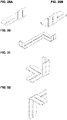
- FIGS. 13-32 show further perspective views of further connecting elements or components.
- the components can be configured differently and have several metal parts/arms with elongated holes or openings.
- the reference symbols are to be used analogously here.
- the Figures 33-38 show an embodiment of the device according to the invention from different perspectives.
- the device comprises a plurality of connecting elements 1, each of which has at least one elongated hole 3 and is fastened to one another via fastening means 2, so that a frame structure 7 is formed.
- the frame structure 7 can be designed, for example, in the form of a door or its frame and thus comprise two posts and one or more crossbeams interconnecting the posts.
- rollers 8 are arranged on the underside of the frame structure 7 .
- the rollers can be fastened to the frame structure 7, for example, via plug-in or screw connections.
- holding elements 9 can be provided.
- the holding elements 9 also consist of connecting elements 1 and extend perpendicularly from the frame construction 7. Between the holding elements 9 and the frame construction 7, there can be connecting elements 1 designed as transverse struts, which strengthen the connection between the holding elements 9 and the frame construction 7 and overall improve the stability of the device .
- the holding elements 9 are arranged offset to one another on opposite sides of the frame construction 7 . Rollers 8 can also be provided on the underside of the holding elements 9 .
- the connecting elements 1 can be attached to a post of the framework 7 and function as spacing means or securing means 10 .
- a support 11 which is formed by one or more connecting elements 1 in the illustrated embodiment.
- a plate-shaped object, such as a door, can be placed or set up on the support 11, which then leans against the frame structure 7 or its post and/or crossbeam.
- Securing means 10 prevent the door to be transported from tipping over during the movement of the device.
- the frame construction 7 can advantageously have a front and rear side 12, 13, so that in a preferred embodiment a device can transport at least two objects, each of which leans against a side of the frame construction 7.
- the frame construction 7 is designed in such a way that it has four sides and can therefore transport four objects. This can be achieved, for example, in that four holding elements 9 are arranged opposite one another on the frame construction 7 and also have a support 11 for an object, so that one object can be placed on the front and rear sides 12, 13 and one object on the sides of the Frame construction 7 can be leaned against.
- the frame construction 7 in such a way that the plate-shaped object or several plate-shaped objects are transported lying down, so that several objects can also be transported in this configuration.
- the frame construction 7 shown as an example can be changed depending on the object to be carried. If, for example, another cross member is advantageous at the front, which extends between the posts, this can be provided by connecting a plurality of connecting elements 1 and connected to the posts by means of fastening means 2 . This would be advantageous, for example, when transporting objects that are shorter than the distance between the posts.
- the length of the frame construction 7 variable. That is, depending on the object, the frame construction 7 can be made longer or shorter by adding or removing connecting elements 1 to the cross member connecting the posts. The same applies to the height of the posts, which can be varied by removing or adding connection elements.
- a significant advantage of the device according to the invention is that the devices carrying objects can be stacked by arranging the devices one behind the other, which is exemplified in Figures 37 , 38 is shown. This is particularly advantageous when several devices in transported in a loading space of a vehicle or temporarily stored in a room. As a result, little storage space is required.
- the devices can be stacked one behind the other to save space when loaded or unloaded.
Landscapes
- Engineering & Computer Science (AREA)
- Chemical & Material Sciences (AREA)
- Combustion & Propulsion (AREA)
- Transportation (AREA)
- Mechanical Engineering (AREA)
- Handcart (AREA)
- Pallets (AREA)
Abstract
Description
- Die Erfindung betrifft eine Vorrichtung zum Tragen mindestens eines plattenförmigen Objektes, wie beispielsweise einer Tür oder einem Fenster mit mehreren Verbindungselementen.
- Es sind Tragsysteme für Türen bekannt, die aus mehreren Teilen zusammengebaut werden können. In der Regel sind solche Tragsysteme derart konstruiert, dass zum Beispiel Schienen mittels Befestigungsmittel miteinander verbindbar sind und so ein schienen- oder rinnenförmiges Tragsystem bildbar ist, an denen Türen befestigbar sind.
- Aus der
EP 2 145 298 B1 ist eine Einrichtung zum Transport von Gegenständen zu Verteilpunkten bekannt, die in den Laderaum eines Fahrzeuges eingebracht wird. Diese Einrichtung umfasst ein fahrbares Regalmodul, welches mehrere Ebenen zur Aufnahme von Gegenständen aufweist, wobei das Regalmodul mit Rädern ausgebildet ist und so in den Laderaum des Fahrzeuges eingeschoben wird. - Nachteilig bei den bekannten Systemen ist, dass die Türen liegend aufgenommen werden und für den Transport viel Platz oder Stauraum benötigt wird. Andererseits können die Türen auch stehend transportiert werden, indem sie an einem Regal oder einem Haltesystem in einem Fahrzeug befestigt werden. Für den Weitertransport außerhalb des Fahrzeuges muss dann diese Verbindung gelöst und ein weiteres Transportmittel gefunden werden.
- Der Erfindung liegt die Aufgabe zugrunde, ein einfaches und flexibles Transportmittel für plattenförmige Objekte bereitzustellen, das auch in z. B. einen Laderaum eines Fahrzeuges einbringbar ist.
- Die Aufgabe wird erfindungsgemäß dadurch gelöst, dass eine Vorrichtung zum Tragen mindestens eines plattenförmigen Objektes mit mehreren Verbindungselementen bereitgestellt wird, wobei die Verbindungselemente mindestens ein Langloch zur Durchführung mindestens eines Befestigungsmittels aufweisen und die Verbindungselemente derart zueinander anordbar sind, dass ein Befestigungsmittel durch mindestens zwei Langlöcher zweier Verbindungselemente ragt, so dass eine aufrechte oder senkrecht zum Boden stehende Rahmenkonstruktion gebildet ist, an die wenigstens das Objekt anlehnbar ist, wobei an einer Unterseite der Rahmenkonstruktion Rollen zum Bewegen der Vorrichtung angebracht sind.
- Im Sinne der Erfindung können verschiedenartige plattenförmige Objekte mit der erfindungsgemäßen Vorrichtung in einfacher Weise transportiert werden. Derartige Objekte umfassen beispielsweise, aber nicht abschließend Tür, Fenster, Tischplatte, Küchenarbeitsplatte, Holzplatte, Metallplatte, Kunststoffplatte, Fliesen, flächige Kunstwerke wie beispielsweise Bilder oder dergleichen.
- In einer bevorzugten Ausgestaltung ist die Rahmenkonstruktion aufrecht oder senkrecht zum Boden ausgebildet, so dass ein Objekt im Wesentlichen aufrecht, insbesondere auf einer der Schmalseiten liegend transportierbar ist. Die erfindungsgemäße Ausgestaltung ermöglicht jedoch, dass das Objekt auch waagerecht, insbesondere auf der Längsseite liegend transportierbar ist. Des Weiteren kann es vorteilhaft sein, wenn das zu transportierende Objekt liegend, das heißt auf einer seiner Flächen aufliegend von der Vorrichtung transportiert wird. Als Beispiel sei hier eine zu transportierende Tür genannt, die auf dem Türblatt aufliegt. Dies ist insbesondere dann von Vorteil, wenn mehrere flächige Elemente in einfacher Weise stapelbar sind und hierdurch einfach transportiert werden können.
- Ein wesentlicher Vorteil der Erfindung ist, dass die Vorrichtung flexibel errichtet werden kann und in einfacher Weise an die Größe eines zu transportierenden Objektes anpassbar ist. Außerdem kann die Vorrichtung auch einfach in den Laderaum eines Fahrzeuges eingebracht und dort mitsamt dem Objekt angeordnet werden. Mehrere Vorrichtungen können hintereinander in dem Laderaum angeordnet, im Wesentlichen gestapelt werden, so dass der zur Verfügung stehenden Stauraum optimal genutzt ist. Die erfindungsgemäße Vorrichtung ist somit für den Laderaum und den Transport außerhalb des Fahrzeuges verwendbar.
- Die Verbindungselemente werden im Sinne der Erfindung auch als Bauteile bezeichnet. Die Verbindungselemente können unterschiedliche Längen aufweisen, so dass sich verschieden große Rahmenkonstruktionen bilden lassen, indem je nach Bedarf unterschiedlich lange Verbindungselemente miteinander verbunden werden. Hierbei durchragt ein Befestigungsmittel, wie beispielsweise eine Schraube oder ein Bolzen zwei Verbindungselemente, die im Wesentlichen derart zueinander angeordnet sind, dass das Befestigungsmittel beide Langlöcher durchragen kann. Hierbei müssen die Langlöcher nicht deckungsgleich übereinanderliegen. Vielmehr ist eine bereichsweise Überlappung der Langlöcher ausreichend, so dass das Befestigungsmittel hindurchragen kann. Aufgrund der Langlöcher können die Verbindungselemente in unterschiedlichen Winkeln zueinander und versetzt zueinander befestigt werden.
- Es ist insbesondere vorteilhaft, wenn die Verbindungselemente eine rechteckige Form mit mindestens einem im Wesentlichen koaxial zu einer Längsachse der Verbindungselemente verlaufendem Langloch aufweisen. Das Langloch kann vorteilhafterweise entlang der Längsachse eines Verbindungselementes verlaufen. Die Länge und Breite des Langlochs kann bei den Verbindungselementen variieren und unterschiedlich gestaltet sein. So können Verbindungselemente mit kürzeren und Verbindungselemente mit längeren Langlöchern bereitgestellt werden. Hierdurch können verschiedenartige Flächen durch Kombination verschiedenartiger Verbindungselemente gebildet werden.
- Es kann jedoch auch bevorzugt sein, dass mindestens ein Langloch eines Verbindungselementes quer zur Längsachse des Verbindungselementes vorliegt.
- Ein Verbindungselement weist mindestens ein Langloch auf. Es kann jedoch auch vorteilhaft sein, wenn die Verbindungselemente eine rechteckige Form mit mindestens zwei hintereinander im Wesentlichen mittig vorliegenden separaten Langlöchern aufweisen. Hierdurch ist ein Verbindungselement mit z. B. zwei separaten Verbindungselementen über die beiden Langlöcher verbindbar.
- Es kann auch vorgesehen sein, dass die Verbindungselemente zwei Arme umfassen, die in einem rechten Winkel zueinanderstehen, so dass die Längsachsen der Arme in einem Winkel von 90° zueinanderstehen, wobei die insbesondere flächig ausgebildeten Arme in einer Ebene liegen. Die beiden Arme der Verbindungselemente, die in einem rechten Winkel zueinanderstehen, weisen vorteilhafterweise jeweils mindestens ein Langloch auf, wobei die Längsachsen der Langlöcher in einem Winkel von 90° zueinanderstehen. Hierdurch ist je ein Arm mit einem anderen Verbindungselement verbindbar. Es kann jedoch auch vorteilhaft sein, wenn die Verbindungselemente aus zwei Armen bestehen, die in einem Winkel zueinanderstehen, der über oder unter 90° liegt, wobei die insbesondere flächig ausgebildeten Arme in einer Ebene liegen. Das heißt, die Längsachsen der Arme stehen insbesondere in einem Winkel zueinander, der über oder unter 90° liegt. Je nach Anwendung können die Arme in einem unter 90° oder in einem über 90° liegendem Winkel zueinander ausgerichtet sein, wobei vorteilhafterweise in jedem Arm mindestens ein Langloch vorliegt, über das die Arme mit weiteren Verbindungselementen verbindbar sind.
- Die Verbindungselemente können in einer Ausgestaltung aus Metall bestehen. Metall weist für das Tragen und Führen einer Tür die notwendigen physikalischen Eigenschaften auf. Als Metall kann beispielsweise ein Stahl verwendet werden. Es können jedoch auch faserverstärkte Kunststoffe verwendet oder mit einem Metall kombiniert werden.
- Die Form der Verbindungselemente kann unterschiedlich gestaltet sein. So können die Verbindungselemente viereckig, rechteckig, mehreckig, quadratisch oder rund sein. Bevorzugt ist es, wenn die Verbindungselemente eben oder geknickt ausgestaltet sind. Gerade bei Verbindungselementen mit zwei Armen kann es vorteilhaft sein, wenn die Arme gewinkelt zueinander ausgerichtet sind, so dass deren Längsachsen in voneinander verschiedenen Ebenen liegen. Hierbei kann es vorteilhaft sein, dass bei der geknickten Ausgestaltung zwei Flächen in einem Winkel von 90° zueinanderstehen. Es kann jedoch auch vorteilhaft sein, dass bei der geknickten Ausgestaltung zwei Flächen in einem Winkel von mehr oder weniger als 90° zueinanderstehen.
- Die an der Rahmenkonstruktion vorliegenden Rollen können feststellbar oder arretierbar gestaltet sein. Dies ist insbesondere vorteilhaft, wenn eine Bewegung der Vorrichtung verhindert werden soll. Die Anzahl der Rollen an der Rahmenkonstruktion kann je nach Anwendung angepasst werden. Hierfür können die Rollen, sprich deren Rollkörper z. B. an der Unterseite der Rahmenkonstruktion angeschraubt werden, wobei auch Steckverbindungen möglich sind, mit denen die Rollen einfach in entsprechende Aufnahmen in der Rahmenkonstruktion einsteckbar sind.
- Um die Stabilität der Rahmenkonstruktion und deren Bewegbarkeit zu verbessern, kann vorgesehen sein, dass die Rahmenkonstruktion von ihr im Wesentlichen senkrecht abstehende Halteelemente aufweist, an denen Rollen angeordnet sind. Die Halteelemente bestehen ebenfalls aus den Verbindungselementen und sind insbesondere im unteren Bereich der Rahmenkonstruktion angeordnet, so dass sie einen Fuß oder mehrere Füße bilden, die vorzugsweise an gegenüberliegenden Seiten der Rahmenkonstruktion senkrecht von ihr abstehen. Die Rahmenkonstruktion weist insbesondere eine Vorder- und eine Rückseite auf, wobei mindestens ein Halteelement pro Vorder- bzw. Rückseite angeordnet ist. Bei Bedarf können auch mehrere Halteelemente an der Rahmenkonstruktion angebracht sein. Die Halteelemente weisen vorzugsweise Rollen an ihren Unterseiten auf. Die Rollen können beispielsweise über Schraub- oder Steckverbindungen an den Halteelementen befestigt sein.
- Des Weiteren kann es vorteilhaft sein, dass die Rahmenkonstruktion in ihrem unteren Bereich durch die Verbindungselemente gebildete Auflagen aufweist, auf die das zu transportierende Objekt auflegbar ist. Derartige Auflagen können von entsprechend ausgebildeten Verbindungselementen gebildet sein. Hierfür eignen sich insbesondere Verbindungselemente, die gewinkelt oder geknickt geformt sind. Es kann jedoch auch vorgesehen sein, dass eine sonstige Auflage an der Rahmenkonstruktion mittels Schraub- oder Steckverbindungen befestigt wird. Hierbei kann es sich beispielsweise um ein Metallgitter, ein Brett, eine Metallleiste oder um ein sonstiges flächiges Element handeln. Die Position der Auflage befindet sich vorteilhafterweise im unteren Bereich der Rahmenkonstruktion, kann aber aufgrund der reversiblen Verbindung zwischen Auflage und Rahmenkonstruktion variiert und an die Maße des zu transportierenden Objektes angepasst werden.
- Es kann vorgesehen sein, dass die Rahmenkonstruktion eine Vorder- und eine Rückseite aufweist und jeweils ein Objekt an die Vorder- und Rückseite anlehnbar ist. Hierdurch können mehrere Objekte von einer Vorrichtung in einfacher Weise transportiert werden, ohne dass hierfür mehr Platz oder Stauraum benötigt wird. Selbstverständlich kann die Vorrichtung auch dazu benutzt werden, um z. B. mehrere verschiedenartige Objekte zu transportieren. Als Beispiel hierfür sei der Transport von plattenförmigen Objekten genannt, die dazu dienen, eine Küche zu bilden. Die Objekte können hierbei beispielsweise eine Tischplatte oder eine Arbeitsplatte darstellen, die gemeinsam mit einer Schrankwand mithilfe der Vorrichtung transportiert werden.
- Um eine Beschädigung des Objektes bzw. der Rahmenkonstruktion zu vermeiden, kann vorgesehen sein, dass die Rahmenkonstruktion Abstandsmittel aufweist, mit denen der Abstand zwischen Rahmenkonstruktion und Objekt einstellbar ist. Hierbei kann es sich beispielsweise um Verbindungselemente handeln, die mittels Schraubverbindungen beabstandet zur Rahmenkonstruktion, insbesondere deren seitliche Pfosten angeordnet sind. Je nach Maße des zu transportierenden Objektes können derartige Abstandsmittel variabel angebracht und deren Position leicht verändert werden. Bevorzugt sind beispielsweise gewinkelte Verbindungselemente. Des Weiteren können als Abstandsmittel auch sonstige aus Metall oder Kunststoff hergestellte Bauteile benutzt werden, die an der Rahmenkonstruktion befestigt werden und an die sich ein zu transportierendes Objekt lehnen kann.
- Um ein Kippen des zu transportierenden Objektes zu verhindern, kann vorgesehen sein, dass die Rahmenkonstruktion verstellbare Sicherungsmittel aufweist, die aus einer Beladestellung in eine Sicherungsstellung bringbar sind, in der eine Bewegung des aufgenommenen Objektes mindestens eingeschränkt ist. In der Beladestellung ist quasi die Rahmenkonstruktion zugänglich, das heißt, ein Objekt kann angelehnt werden, wogegen in der Sicherungsstellung dies nicht möglich ist. In der Sicherungsstellung lehnt sich das Objekt insbesondere an die Rahmenkonstruktion und ein Entfernen des Objektes ist durch die sich in der Sicherungsstellung befindlichen Sicherungsmittel nicht möglich. Die Sicherungsmittel können aus Haken, Riegel oder derartiges gebildet sein und so an der Rahmenkonstruktion befestigt werden, dass sie zum Beladen der Vorrichtung in eine Beladestellung verschwenkbar und nach dem Beladen in eine Sicherungsstellung bringbar sind, in der das zu transportierende Objekt nicht kippen kann. Als Sicherungsmittel können auch entsprechend ausgebildete Verbindungselemente genutzt werden.
- Des Weiteren kann vorgesehen sein, dass die Rahmenkonstruktion Schutzelemente aufweist, die aus einem elastischen Material bestehen und an der Rahmenkonstruktion vorliegen, um eine Beschädigung des aufgenommenen Objektes und/oder der Rahmenkonstruktion zu verhindern. Hierbei kann es sich beispielsweise um Schaumstoff oder Gummielemente handeln die reversibel an der Rahmenkonstruktion und/oder des zu transportierenden Objektes befestigbar sind. Gerade bei dem Transport plattenförmiger Objekte wie beispielsweise einem Gemälde oder einem Kunstwerk ist es vorteilhaft, wenn dieses mit dem Schutzelemente oder mit Schutzelementen vor eine Beschädigung geschützt ist.
- Ferner betrifft die Erfindung einen Bausatz umfassend Verbindungselemente, Befestigungselemente und Rollen zum Aufbau einer Vorrichtung nach einem oder mehreren der vorhergehenden Ansprüche. Die erfindungsgemäße Vorrichtung kann vorteilhafterweise als Bausatz transportiert werden, sodass ein einfacher Versand und Transport der Vorrichtung in Gestalt eines Bausatzes möglich ist. Der Bausatz kann bei Bedarf und vor Ort montiert bzw. demontiert werden.
- Die Erfindung wird nachfolgend anhand von Ausführungsbeispielen der Erfindung näher erläutert, die in der Zeichnung dargestellt sind. Es zeigen
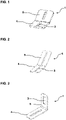
- Figur 1
- perspektivische Ansicht einer Ausgestaltung eines gewinkelten Verbindungselements,
- Figur 2
- perspektivische Ansicht einer weiteren Ausgestaltung eines gewinkelten Verbindungselements,
- Figur 3
- perspektivische Ansicht einer weiteren Ausgestaltung eines gewinkelten Verbindungselements,
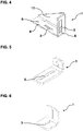
- Figur 4
- perspektivische Ansicht einer weiteren Ausgestaltung eines gewinkelten Verbindungselements mit Wandelement,
- Figur 5
- perspektivische Ansicht einer weiteren Ausgestaltung eines gewinkelten Verbindungselements,
- Figur 6
- perspektivische Ansicht einer weiteren Ausgestaltung eines gewinkelten Verbindungselements,
- Figur 7
- perspektivische Ansicht einer weiteren Ausgestaltung eines gewinkelten Verbindungselements,
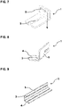
- Figur 8
- perspektivische Ansicht einer Ausgestaltung eines geknickten Verbindungselements,
- Figur 9
- perspektivische Ansicht einer weiteren Ausgestaltung eines gewinkelten Verbindungselements mit vier Langlöchern,
- Figur 10
- perspektivische Ansicht einer weiteren Ausgestaltung eines gewinkelten Verbindungselements mit vier Langlöchern,
- Figur 11
- eine Draufsicht einer Ausgestaltung eines Verbindungsteils mit zwei Langlöchern,
- Figur 12
- eine perspektivische Ansicht einer weiteren Ausgestaltung eines gewinkelten Verbindungselements mit zwei Langlöchern
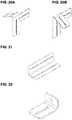
- Figuren 13-32
- weitere perspektivische Ansichten weiterer Verbindungselemente und
- Figuren 33-38
- beispielhafte Ausgestaltungen der erfindungsgemäßen Vorrichtung.
- In den
Figuren 1 bis 12 sind bevorzugte Ausgestaltungen von Verbindungselementen dargestellt. Erfindungsgemäße Vorrichtung umfasst mehrere Verbindungselemente 1, die über inFigur 13 gezeigte Befestigungsmittel 2 miteinander verbunden sind. Die Verbindungselemente 1 sind vorzugsweise als länglich gestaltete flache Rechtecke ausgeführt. Die Verbindungselemente 1 können jedoch vollständig oder bereichsweise auch andere geometrische Formen aufweisen. So kann beispielsweise ein Ende eines Verbindungselementes 1 spitzzulaufend oder abgerundet gestaltet sein. Die Höhe der Verbindungselemente 1 kann beispielsweise im Bereich von 0,5 cm bis 5 cm liegen oder mehr oder weniger. Die Höhe und/oder auch Breite der Verbindungselemente 1 kann über ihre Länge variieren, das heißt, die Höhe und/oder Breite kann über die Länge abnehmen oder zunehmen. Jedes Verbindungselement 1 umfasst mindestens ein Langloch 3, das zumindest bereichsweise entlang der Längsachse der Verbindungselemente 1 verläuft. Die Länge des Langlochs 3 kann zwischen den Verbindungselementen 1 variieren, so dass die Langlöcher 3 der Verbindungselemente 1 unterschiedliche Längen und/oder Breiten aufweisen können. Das Langloch 3 kann entgratete Enden umfassen, so dass das Langloch 3 keine Ecken aufweist. Enden mit Ecken können jedoch auch vorteilhaft sein. - Die Verbindungselemente 1 können zwei- oder mehrarmig ausgestaltet sein, wobei in jedem Arm 4, 5 wenigstens ein Langloch 3 angeordnet sein kann. Die Arme 4, 5 können derart zueinander angeordnet sein, dass sie in einem Winkel von 90° oder mehr oder weniger als 90° zueinanderstehen. Hierbei liegen die Längsachsen der Arme 4, 5 vorzugsweise in einer senkrecht zur Fläche der Verbindungselemente 1 verlaufenden Ebene. Die Langlöcher 3 der Arme 4, 5 verlaufen entlang der Längsachsen der Arme 4, 5. Die Länge und Breite der Langlöcher 3 der Arme 4, 5 eines Verbindungselementes1 kann unterschiedlich sein, wie beispielsweise in den
Figuren 3 und5 zu erkennen ist. Bei dieser Ausgestaltung sind die Arme 4, 5 über die Schmalseite eines Verbindungselementes 1 verbunden. - In
Figur 4 ist eine Ausgestaltung eines Verbindungselements 1 gezeigt, bei dem zwischen den Armen 4, 5 ein Wandelement 12 integriert ist. - In einer weiteren Ausgestaltung, die in den
Figuren 7 und 8 beispielhaft dargestellt ist, sind die Langlöcher 3 der Arme 4, 5 nicht in einer Ebene angeordnet, sondern ein Langloch 3 eines Arms 4, 5 ist im Wesentlichen quer zum Langloch 3 des anderen Arms 4, 5 angeordnet. Je nach Ausgestaltung kann somit, wie gut inFigur 8 erkennbar, ein erster Arm 4 des Verbindungselementes 1 länger vorgesehen sein, wie der zweite Arm 5. Der zweite Arm 5 ist zum ersten Arm 4 geknickt angeordnet. - Eine weitere Ausgestaltung ist in den
Figuren 9 und10 gezeigt, bei der das Verbindungselement 1 ebenfalls zwei Arme 4, 5 aufweist, die jedoch über die Längsseite des Verbindungselementes 1 verbunden und zueinander in einem 90° Winkel angeordnet sind. Die dargestellten Arme 4, 5 weisen jeweils zwei Langlöcher 3 auf, deren Längsachsen quasi parallel verlaufen. - Es kann vorgesehen sein, dass die Verbindungselemente 1 neben mindestens einem Langloch 3 weitere Bohrungen 6 zur Aufnahme von Befestigungsmitteln aufweisen, was beispielhaft in den
Figuren 4 und7 angedeutet ist. Hierdurch sind weitere oder stabilere Verbindungen möglich. Denn durch die Bohrung 6 kann ebenfalls ein Befestigungsmittel durchgeführt werden, so dass zwei Verbindungselemente 1 verbindbar sind. -
Figur 11 zeigt ein langgestrecktes, ebenes Verbindungselement 1 mit zwei hintereinander angeordneten Langlöchern 3. Ein gewinkeltes Verbindungselement 1 ist inFigur 12 dargestellt, bei dem das Verbindungselement 1 im Wesentlichen aus zwei Armen 4, 5 besteht, die in einem 90° Winkel zueinander angeordnet sind, wobei in jedem Arm 4, 5 jeweils ein Langloch 3 vorliegt. Das heißt, die Langlöcher 3 liegen in einer Ebene und die Längsachsen der Langlöcher stehen senkrecht zueinander. - Die
Figuren 13-32 zeigen weitere perspektivische Ansichten weiterer Verbindungselemente bzw. Bauteile. Die Bauteile können unterschiedlich ausgestaltet sein und mehrere Metallteile/Arme mit Langlöchern oder Durchbrüchen aufweisen. Die Bezugszeichen sind hier analog anzuwenden. - Die
Figuren 33-38 zeigen eine Ausgestaltung der erfindungsgemäßen Vorrichtung aus verschiedenen Perspektiven. Die Vorrichtung umfasst mehrere Verbindungselemente 1, die jeweils mindestens ein Langloch 3 aufweisen und über Befestigungsmittel 2 miteinander befestigt sind, sodass eine Rahmenkonstruktion 7 gebildet wird. Die Rahmenkonstruktion 7 kann beispielsweise in Gestalt einer Tür bzw. deren Rahmen ausgebildet sein und so zwei Pfosten und einen oder mehrere die Pfosten miteinander verbindende Querträger umfassen. - An der Unterseite der Rahmenkonstruktion 7 sind Rollen 8 angeordnet. Die Rollen können beispielsweise über Steck- oder Schraubverbindungen an der Rahmenkonstruktion 7 befestigt sein. Hierbei handelt es sich vorzugsweise um Rollen 8, die um ihre Längsachse drehbar gelagert sind, sodass die Rollen um 360° drehbar sind.
- Um die Stabilität der Rahmenkonstruktion 7 zu verbessern, können Halteelemente 9 vorgesehen sein. Die Halteelemente 9 bestehen ebenfalls aus Verbindungselementen 1 und erstrecken sich senkrecht von der Rahmenkonstruktion 7. Zwischen den Halteelementen 9 und der Rahmenkonstruktion 7 können als Querbestrebungen ausgebildete Verbindungselemente 1 vorliegen, die die Verbindung zwischen Haltelemente 9 und Rahmenkonstruktion 7 verstärken und insgesamt die Stabilität der Vorrichtung verbessern. Die Halteelemente 9 sind in der dargestellten Ausgestaltung an gegenüberliegenden Seiten der Rahmenkonstruktion 7 versetzt zueinander angeordnet. An den Halteelementen 9 können ebenfalls Rollen 8 an deren Unterseite vorgesehen sein.
- Die Verbindungselemente 1 können an einem Pfosten der Rahmenkonstruktion 7 angebracht sein und als Abstandsmittel oder Sicherungsmittel 10 fungieren. Im unteren Bereich der Rahmenkonstruktion 7 ist eine Auflage 11 vorgesehen die in der dargestellten Ausgestaltung durch ein oder mehrere Verbindungselemente 1 gebildet wird. Auf die Auflage 11 kann ein plattenförmiges Objekt, wie beispielsweise eine Tür aufgelegt oder aufgestellt werden, die sich dann an der Rahmenkonstruktion 7 bzw. deren Pfosten und/oder Querträger anlehnt. Durch Sicherungsmittel 10 wird ein Kippen der zu transportierenden Tür während der Bewegung der Vorrichtung verhindert.
- Die Rahmenkonstruktion 7 kann vorteilhafterweise eine Vorder- und Rückseite 12, 13 aufweisen, sodass eine Vorrichtung in einer bevorzugten Ausgestaltung mindestens zwei Objekte transportieren kann, die sich jeweils an eine Seite der Rahmenkonstruktion 7 lehnen. In einer nicht dargestellten Ausgestaltung kann vorgesehen sein, dass die Rahmenkonstruktion 7 derart gestaltet ist, dass sie vier Seiten aufweist und somit vier Objekte transportieren kann. Dies kann beispielsweise dadurch erreicht werden, dass vier Halteelemente 9 gegenüberliegend an der Rahmenkonstruktion 7 angeordnet sind und ebenfalls eine Auflage 11 für ein Objekt aufweisen, so dass jeweils ein Objekt an der Vorder- und Rückseite 12, 13 und jeweils ein Objekt an den Seiten der Rahmenkonstruktion 7 anlehnbar ist. Des Weiteren ist möglich, die Rahmenkonstruktion 7 derart zu gestalten, dass das plattenförmige Objekt bzw. mehrere plattenförmige Objekte liegend transportiert werden, sodass auch bei dieser Ausgestaltung mehrere Objekte transportierbar sind. Selbstverständlich kann die beispielhaft gezeigte Rahmenkonstruktion 7 in Abhängigkeit des zu tragenden Objektes verändert werden. Ist zum Beispiel ein weiterer Querträger vorn Vorteil, der sich zwischen den Pfosten erstreckt, kann dieser durch die Verbindung mehrerer Verbindungselemente 1 bereitgestellt und mittels Befestigungsmittel 2 mit den Pfosten verbunden werden. Dies wäre zum Beispiel bei einem Transport von Objekten von Vorteil, die kürzer als der Abstand zwischen den Pfosten ist. Ferner ist es möglich, die Länge der Rahmenkonstruktion 7 variabel zu gestalten. Das heißt, je nach Objekt kann die Rahmenkonstruktion 7 länger oder kürzer gestaltet werden, indem Verbindungselemente 1 zum die Pfosten verbindenden Querträger hinzugefügt oder entfernt werden. Gleiches gilt für die Höhe der Pfosten, die durch die Entnahme oder das Hinzufügen von Verbindungselementen variiert werden kann.
- Ein wesentlicher Vorteil der erfindungsgemäßen Vorrichtung ist, dass sich die Objekte tragenden Vorrichtungen stapeln lassen, indem die Vorrichtungen hintereinander angeordnet werden, was beispielhaft in
Figuren 37 ,38 gezeigt ist. Dies ist insbesondere dann vorteilhaft, wenn mehrere Vorrichtungen in einem Laderaum eines Fahrzeuges transportiert oder in einem Raum zwischengelagert werden. Hierdurch wird wenig Stauraum benötigt. Die Vorrichtungen können im beladenen oder unbeladenen Zustand platzsparend hintereinander gestapelt werden.
Claims (15)
- Vorrichtung zum Tragen mindestens eines plattenförmigen Objektes mit mehreren Verbindungselementen (1), wobei die Verbindungselemente (1) mindestens ein Langloch (3) zur Durchführung mindestens eines Befestigungsmittels (2) aufweisen und die Verbindungselemente (1) derart zueinander anordbar sind, dass ein Befestigungsmittel (2) durch mindestens zwei Langlöcher (3) zweier Verbindungselemente (1) ragt, so dass eine Rahmenkonstruktion (7) gebildet ist, an die wenigstens das Objekt anlehnbar ist, wobei an einer Unterseite der Rahmenkonstruktion (7) Rollen (8) zum Bewegen der Vorrichtung angebracht sind.
- Vorrichtung nach Anspruch 1, dadurch gekennzeichnet, dass die Verbindungselemente (1) eine rechteckige Form mit mindestens einem im Wesentlichen koaxial zu einer Längsachse der Verbindungselemente (1) verlaufendem Langloch (3) aufweisen.
- Vorrichtung nach Anspruch 1, dadurch gekennzeichnet, dass die Verbindungselemente (1) eine rechteckige Form mit mindestens zwei hintereinander im Wesentlichen mittig vorliegenden separaten Langlöchern (3) aufweisen.
- Vorrichtung nach einem der vorhergehenden Ansprüche, dadurch gekennzeichnet, dass die Verbindungselemente (1) aus zwei Armen (4, 5) bestehen, die in einem rechten Winkel zueinanderstehen.
- Vorrichtung nach einem der Ansprüche 1 bis 3, dadurch gekennzeichnet, dass die Verbindungselemente (1) aus zwei Armen (4, 5) bestehen, die in einem Winkel zueinanderstehen, der über oder unter 90° liegt.
- Vorrichtung nach einem der vorhergehenden Ansprüche, dadurch gekennzeichnet, dass in jedem der beiden Arme (4, 5) jeweils mindestens ein Langloch (3) und/oder oder ein Durchbruch vorliegt.
- Vorrichtung nach einem der vorhergehenden Ansprüche, dadurch gekennzeichnet, dass die Verbindungselemente (1) eben oder geknickt ausgestaltet sind.
- Vorrichtung nach einem der vorhergehenden Ansprüche, dadurch gekennzeichnet, dass die Rollen (8) feststellbar sind.
- Vorrichtung nach einem der vorhergehenden Ansprüche, dadurch gekennzeichnet, dass die Rahmenkonstruktion (7) von ihr im Wesentlichen senkrecht abstehende Halteelemente (9) aufweist, an denen Rollen (8) angeordnet sind.
- Vorrichtung nach einem der vorhergehenden Ansprüche, dadurch gekennzeichnet, dass die Rahmenkonstruktion (7) in ihrem unteren Bereich durch die Verbindungselemente (1) gebildete Auflagen (11) aufweist, auf die das Objekt auflegbar ist.
- Vorrichtung nach einem der vorhergehenden Ansprüche, dadurch gekennzeichnet, dass die Rahmenkonstruktion (7) eine Vorder- und eine Rückseite (12, 13) aufweist und jeweils ein Objekt an die Vorder- und Rückseite (12, 13) anlehnbar ist.
- Vorrichtung nach einem der vorhergehenden Ansprüche, dadurch gekennzeichnet, dass die Rahmenkonstruktion (7) Abstandsmittel (10) aufweist, mit denen der Abstand zwischen Rahmenkonstruktion (7) und Objekt einstellbar ist.
- Vorrichtung nach einem der vorhergehenden Ansprüche, dadurch gekennzeichnet, dass die Rahmenkonstruktion (7) verstellbare Sicherungsmittel (10) aufweist, die aus einer Beladestellung in eine Sicherungsstellung bringbar sind, in der eine Bewegung eines aufgenommenen Objektes mindestens eingeschränkt ist.
- Vorrichtung nach einem der vorhergehenden Ansprüche, dadurch gekennzeichnet, dass die Rahmenkonstruktion (7) Schutzelemente aufweist, die aus einem elastischen Material bestehen und an der Rahmenkonstruktion (7) vorliegen, um eine Beschädigung eines aufgenommenen Objektes und/oder der Rahmenkonstruktion (7) zu verhindern.
- Bausatz umfassend Verbindungselemente (1), Befestigungselemente (2) und Rollen (8) zum Aufbau einer Vorrichtung nach einem oder mehreren der vorhergehenden Ansprüche.
Applications Claiming Priority (2)
| Application Number | Priority Date | Filing Date | Title |
|---|---|---|---|
| DE102020125888 | 2020-10-02 | ||
| DE202021100811.3U DE202021100811U1 (de) | 2020-03-03 | 2021-02-18 | Vorrichtung zum Tragen mindestens einer Tür oder eines Fensters |
Publications (2)
| Publication Number | Publication Date |
|---|---|
| EP3978397A1 true EP3978397A1 (de) | 2022-04-06 |
| EP3978397B1 EP3978397B1 (de) | 2024-04-17 |
Family
ID=80442721
Family Applications (1)
| Application Number | Title | Priority Date | Filing Date |
|---|---|---|---|
| EP21185506.9A Active EP3978397B1 (de) | 2020-10-02 | 2021-07-14 | Vorrichtung zum tragen mindestens eines plattenförmigen objektes |
Country Status (2)
| Country | Link |
|---|---|
| EP (1) | EP3978397B1 (de) |
| PL (1) | PL3978397T3 (de) |
Cited By (3)
| Publication number | Priority date | Publication date | Assignee | Title |
|---|---|---|---|---|
| CN115417060A (zh) * | 2022-09-08 | 2022-12-02 | 天津海之凰环境科技有限公司 | 一种基于mabr膜组件架的移动装置及其使用方法 |
| CN117508302A (zh) * | 2023-12-26 | 2024-02-06 | 山东中恒建设集团有限公司 | 一种建筑装饰板材运输装置 |
| DE102023124852A1 (de) * | 2023-09-14 | 2025-04-03 | TRUMPF Werkzeugmaschinen SE + Co. KG | Vorrichtung zum Aufnehmen eines Werkstücks, eine Laser- oder Plasmaschneidvorrichtung sowie ein Verfahren zum Montieren und/oder Demontieren einer solchen Vorrichtung |
Citations (6)
| Publication number | Priority date | Publication date | Assignee | Title |
|---|---|---|---|---|
| US4166638A (en) * | 1978-04-25 | 1979-09-04 | Alfred De Prado | Adjustable dolly |
| DE4444413A1 (de) * | 1994-12-14 | 1996-06-20 | Siegfried Fricker | Bausatz für Skelettkonstrukionen wie Regale, Rahmen, Ständer u. dgl. |
| CA2582080A1 (en) * | 2007-03-16 | 2008-09-16 | Dany Marquette | Dolly |
| JP2009161044A (ja) * | 2008-01-07 | 2009-07-23 | Asahi:Kk | 組立台車 |
| EP2145298B1 (de) | 2007-05-09 | 2010-07-28 | Siemens Aktiengesellschaft | Verfahren und einrichtung zum transport von gegenständen zu verteilpunkten |
| USD729043S1 (en) * | 2012-09-14 | 2015-05-12 | Float-On Corporation | Adjustable bracket |
-
2021
- 2021-07-14 PL PL21185506.9T patent/PL3978397T3/pl unknown
- 2021-07-14 EP EP21185506.9A patent/EP3978397B1/de active Active
Patent Citations (6)
| Publication number | Priority date | Publication date | Assignee | Title |
|---|---|---|---|---|
| US4166638A (en) * | 1978-04-25 | 1979-09-04 | Alfred De Prado | Adjustable dolly |
| DE4444413A1 (de) * | 1994-12-14 | 1996-06-20 | Siegfried Fricker | Bausatz für Skelettkonstrukionen wie Regale, Rahmen, Ständer u. dgl. |
| CA2582080A1 (en) * | 2007-03-16 | 2008-09-16 | Dany Marquette | Dolly |
| EP2145298B1 (de) | 2007-05-09 | 2010-07-28 | Siemens Aktiengesellschaft | Verfahren und einrichtung zum transport von gegenständen zu verteilpunkten |
| JP2009161044A (ja) * | 2008-01-07 | 2009-07-23 | Asahi:Kk | 組立台車 |
| USD729043S1 (en) * | 2012-09-14 | 2015-05-12 | Float-On Corporation | Adjustable bracket |
Cited By (3)
| Publication number | Priority date | Publication date | Assignee | Title |
|---|---|---|---|---|
| CN115417060A (zh) * | 2022-09-08 | 2022-12-02 | 天津海之凰环境科技有限公司 | 一种基于mabr膜组件架的移动装置及其使用方法 |
| DE102023124852A1 (de) * | 2023-09-14 | 2025-04-03 | TRUMPF Werkzeugmaschinen SE + Co. KG | Vorrichtung zum Aufnehmen eines Werkstücks, eine Laser- oder Plasmaschneidvorrichtung sowie ein Verfahren zum Montieren und/oder Demontieren einer solchen Vorrichtung |
| CN117508302A (zh) * | 2023-12-26 | 2024-02-06 | 山东中恒建设集团有限公司 | 一种建筑装饰板材运输装置 |
Also Published As
| Publication number | Publication date |
|---|---|
| PL3978397T3 (pl) | 2024-10-14 |
| EP3978397B1 (de) | 2024-04-17 |
Similar Documents
| Publication | Publication Date | Title |
|---|---|---|
| EP3978397B1 (de) | Vorrichtung zum tragen mindestens eines plattenförmigen objektes | |
| EP2523864A1 (de) | Vorrichtung zum transport von gegenständen | |
| AT16745U1 (de) | Regallagersystem und Regalrahmenteil für ein Regallagersystem | |
| DE202014104238U1 (de) | Tragbarer Montagehubtisch | |
| EP2495187A1 (de) | Transportelement | |
| EP1987735B1 (de) | Blockregal zur Lagerung insbesondere von Fahrzeugrädern | |
| DE102009030072B4 (de) | Fahrzeug | |
| EP3452358B1 (de) | Transportvorrichtung für möbel | |
| DE202020005145U1 (de) | Kragarmregal | |
| EP1568541B1 (de) | Einspannvorrichtung | |
| EP2832664A1 (de) | Lagervorrichtung für einen plattenförmigen Gegenstand | |
| WO2012092955A1 (de) | Stabilisator-schuh für ein regal zur lagerung von gegenständen | |
| DE202021100811U1 (de) | Vorrichtung zum Tragen mindestens einer Tür oder eines Fensters | |
| DE4312668A1 (de) | Verladevorrichtung für Trommelwaren mit Ladungssicherung für den Transport auf Transportfahrzeugen | |
| DE102019117190A1 (de) | Einrichtung zum stirnseitigen Abschluss einer Grabenverbau-Einheit | |
| DE202005020117U1 (de) | Seitenprofil für Rollenbahngestelle | |
| DE19956951C2 (de) | Arbeitsplatzmöbel mit einem Möbelgestell aus vertikalen Säulen und Quertraversen | |
| DE102024104920A1 (de) | Balkon | |
| DE69501468T2 (de) | Lagersystem | |
| DE202021101281U1 (de) | Rungenanordnung und Lageranordnung | |
| DE202016103014U1 (de) | Tischfuß und Tischleiste für einen Arbeitsplatztisch, sowie Arbeitsplatztisch mit einem derartigen Tischfuß bzw. einer derartigen Tischleiste | |
| DE102010007684A1 (de) | Rollenbahn mit werkzeugloser Verbindung der Pfeiler | |
| DE102022107853A1 (de) | Schutzeinrichtung für einen Horizontalförderer | |
| DE3142845A1 (de) | "vorrichtung zum lagern von grossen plattenfoermigen koerpern" | |
| DE9003448U1 (de) | Rollbehälter |
Legal Events
| Date | Code | Title | Description |
|---|---|---|---|
| PUAI | Public reference made under article 153(3) epc to a published international application that has entered the european phase |
Free format text: ORIGINAL CODE: 0009012 |
|
| STAA | Information on the status of an ep patent application or granted ep patent |
Free format text: STATUS: THE APPLICATION HAS BEEN PUBLISHED |
|
| AK | Designated contracting states |
Kind code of ref document: A1 Designated state(s): AL AT BE BG CH CY CZ DE DK EE ES FI FR GB GR HR HU IE IS IT LI LT LU LV MC MK MT NL NO PL PT RO RS SE SI SK SM TR |
|
| STAA | Information on the status of an ep patent application or granted ep patent |
Free format text: STATUS: REQUEST FOR EXAMINATION WAS MADE |
|
| 17P | Request for examination filed |
Effective date: 20221005 |
|
| RBV | Designated contracting states (corrected) |
Designated state(s): AL AT BE BG CH CY CZ DE DK EE ES FI FR GB GR HR HU IE IS IT LI LT LU LV MC MK MT NL NO PL PT RO RS SE SI SK SM TR |
|
| GRAP | Despatch of communication of intention to grant a patent |
Free format text: ORIGINAL CODE: EPIDOSNIGR1 |
|
| STAA | Information on the status of an ep patent application or granted ep patent |
Free format text: STATUS: GRANT OF PATENT IS INTENDED |
|
| GRAS | Grant fee paid |
Free format text: ORIGINAL CODE: EPIDOSNIGR3 |
|
| RIC1 | Information provided on ipc code assigned before grant |
Ipc: B62B 3/18 20060101ALI20240208BHEP Ipc: B62B 3/02 20060101ALI20240208BHEP Ipc: B62B 3/10 20060101ALI20240208BHEP Ipc: B65G 7/04 20060101AFI20240208BHEP |
|
| GRAA | (expected) grant |
Free format text: ORIGINAL CODE: 0009210 |
|
| STAA | Information on the status of an ep patent application or granted ep patent |
Free format text: STATUS: THE PATENT HAS BEEN GRANTED |
|
| INTG | Intention to grant announced |
Effective date: 20240223 |
|
| INTG | Intention to grant announced |
Effective date: 20240223 |
|
| AK | Designated contracting states |
Kind code of ref document: B1 Designated state(s): AL AT BE BG CH CY CZ DE DK EE ES FI FR GB GR HR HU IE IS IT LI LT LU LV MC MK MT NL NO PL PT RO RS SE SI SK SM TR |
|
| REG | Reference to a national code |
Ref country code: GB Ref legal event code: FG4D Free format text: NOT ENGLISH |
|
| REG | Reference to a national code |
Ref country code: CH Ref legal event code: EP |
|
| REG | Reference to a national code |
Ref country code: IE Ref legal event code: FG4D Free format text: LANGUAGE OF EP DOCUMENT: GERMAN Ref country code: DE Ref legal event code: R096 Ref document number: 502021003354 Country of ref document: DE |
|
| REG | Reference to a national code |
Ref country code: LT Ref legal event code: MG9D |
|
| REG | Reference to a national code |
Ref country code: NL Ref legal event code: FP |
|
| PG25 | Lapsed in a contracting state [announced via postgrant information from national office to epo] |
Ref country code: IS Free format text: LAPSE BECAUSE OF FAILURE TO SUBMIT A TRANSLATION OF THE DESCRIPTION OR TO PAY THE FEE WITHIN THE PRESCRIBED TIME-LIMIT Effective date: 20240817 |
|
| PG25 | Lapsed in a contracting state [announced via postgrant information from national office to epo] |
Ref country code: BG Free format text: LAPSE BECAUSE OF FAILURE TO SUBMIT A TRANSLATION OF THE DESCRIPTION OR TO PAY THE FEE WITHIN THE PRESCRIBED TIME-LIMIT Effective date: 20240417 |
|
| PG25 | Lapsed in a contracting state [announced via postgrant information from national office to epo] |
Ref country code: HR Free format text: LAPSE BECAUSE OF FAILURE TO SUBMIT A TRANSLATION OF THE DESCRIPTION OR TO PAY THE FEE WITHIN THE PRESCRIBED TIME-LIMIT Effective date: 20240417 Ref country code: FI Free format text: LAPSE BECAUSE OF FAILURE TO SUBMIT A TRANSLATION OF THE DESCRIPTION OR TO PAY THE FEE WITHIN THE PRESCRIBED TIME-LIMIT Effective date: 20240417 |
|
| PG25 | Lapsed in a contracting state [announced via postgrant information from national office to epo] |
Ref country code: GR Free format text: LAPSE BECAUSE OF FAILURE TO SUBMIT A TRANSLATION OF THE DESCRIPTION OR TO PAY THE FEE WITHIN THE PRESCRIBED TIME-LIMIT Effective date: 20240718 |
|
| PG25 | Lapsed in a contracting state [announced via postgrant information from national office to epo] |
Ref country code: PT Free format text: LAPSE BECAUSE OF FAILURE TO SUBMIT A TRANSLATION OF THE DESCRIPTION OR TO PAY THE FEE WITHIN THE PRESCRIBED TIME-LIMIT Effective date: 20240819 |
|
| PG25 | Lapsed in a contracting state [announced via postgrant information from national office to epo] |
Ref country code: ES Free format text: LAPSE BECAUSE OF FAILURE TO SUBMIT A TRANSLATION OF THE DESCRIPTION OR TO PAY THE FEE WITHIN THE PRESCRIBED TIME-LIMIT Effective date: 20240417 |
|
| PG25 | Lapsed in a contracting state [announced via postgrant information from national office to epo] |
Ref country code: LV Free format text: LAPSE BECAUSE OF FAILURE TO SUBMIT A TRANSLATION OF THE DESCRIPTION OR TO PAY THE FEE WITHIN THE PRESCRIBED TIME-LIMIT Effective date: 20240417 |
|
| PG25 | Lapsed in a contracting state [announced via postgrant information from national office to epo] |
Ref country code: PT Free format text: LAPSE BECAUSE OF FAILURE TO SUBMIT A TRANSLATION OF THE DESCRIPTION OR TO PAY THE FEE WITHIN THE PRESCRIBED TIME-LIMIT Effective date: 20240819 Ref country code: NO Free format text: LAPSE BECAUSE OF FAILURE TO SUBMIT A TRANSLATION OF THE DESCRIPTION OR TO PAY THE FEE WITHIN THE PRESCRIBED TIME-LIMIT Effective date: 20240717 Ref country code: LV Free format text: LAPSE BECAUSE OF FAILURE TO SUBMIT A TRANSLATION OF THE DESCRIPTION OR TO PAY THE FEE WITHIN THE PRESCRIBED TIME-LIMIT Effective date: 20240417 Ref country code: IS Free format text: LAPSE BECAUSE OF FAILURE TO SUBMIT A TRANSLATION OF THE DESCRIPTION OR TO PAY THE FEE WITHIN THE PRESCRIBED TIME-LIMIT Effective date: 20240817 Ref country code: HR Free format text: LAPSE BECAUSE OF FAILURE TO SUBMIT A TRANSLATION OF THE DESCRIPTION OR TO PAY THE FEE WITHIN THE PRESCRIBED TIME-LIMIT Effective date: 20240417 Ref country code: GR Free format text: LAPSE BECAUSE OF FAILURE TO SUBMIT A TRANSLATION OF THE DESCRIPTION OR TO PAY THE FEE WITHIN THE PRESCRIBED TIME-LIMIT Effective date: 20240718 Ref country code: FI Free format text: LAPSE BECAUSE OF FAILURE TO SUBMIT A TRANSLATION OF THE DESCRIPTION OR TO PAY THE FEE WITHIN THE PRESCRIBED TIME-LIMIT Effective date: 20240417 Ref country code: ES Free format text: LAPSE BECAUSE OF FAILURE TO SUBMIT A TRANSLATION OF THE DESCRIPTION OR TO PAY THE FEE WITHIN THE PRESCRIBED TIME-LIMIT Effective date: 20240417 Ref country code: BG Free format text: LAPSE BECAUSE OF FAILURE TO SUBMIT A TRANSLATION OF THE DESCRIPTION OR TO PAY THE FEE WITHIN THE PRESCRIBED TIME-LIMIT Effective date: 20240417 Ref country code: RS Free format text: LAPSE BECAUSE OF FAILURE TO SUBMIT A TRANSLATION OF THE DESCRIPTION OR TO PAY THE FEE WITHIN THE PRESCRIBED TIME-LIMIT Effective date: 20240717 |
|
| PG25 | Lapsed in a contracting state [announced via postgrant information from national office to epo] |
Ref country code: DK Free format text: LAPSE BECAUSE OF FAILURE TO SUBMIT A TRANSLATION OF THE DESCRIPTION OR TO PAY THE FEE WITHIN THE PRESCRIBED TIME-LIMIT Effective date: 20240417 |
|
| REG | Reference to a national code |
Ref country code: DE Ref legal event code: R097 Ref document number: 502021003354 Country of ref document: DE |
|
| PG25 | Lapsed in a contracting state [announced via postgrant information from national office to epo] |
Ref country code: EE Free format text: LAPSE BECAUSE OF FAILURE TO SUBMIT A TRANSLATION OF THE DESCRIPTION OR TO PAY THE FEE WITHIN THE PRESCRIBED TIME-LIMIT Effective date: 20240417 |
|
| PG25 | Lapsed in a contracting state [announced via postgrant information from national office to epo] |
Ref country code: CZ Free format text: LAPSE BECAUSE OF FAILURE TO SUBMIT A TRANSLATION OF THE DESCRIPTION OR TO PAY THE FEE WITHIN THE PRESCRIBED TIME-LIMIT Effective date: 20240417 |
|
| PG25 | Lapsed in a contracting state [announced via postgrant information from national office to epo] |
Ref country code: SK Free format text: LAPSE BECAUSE OF FAILURE TO SUBMIT A TRANSLATION OF THE DESCRIPTION OR TO PAY THE FEE WITHIN THE PRESCRIBED TIME-LIMIT Effective date: 20240417 Ref country code: RO Free format text: LAPSE BECAUSE OF FAILURE TO SUBMIT A TRANSLATION OF THE DESCRIPTION OR TO PAY THE FEE WITHIN THE PRESCRIBED TIME-LIMIT Effective date: 20240417 |
|
| PG25 | Lapsed in a contracting state [announced via postgrant information from national office to epo] |
Ref country code: SM Free format text: LAPSE BECAUSE OF FAILURE TO SUBMIT A TRANSLATION OF THE DESCRIPTION OR TO PAY THE FEE WITHIN THE PRESCRIBED TIME-LIMIT Effective date: 20240417 |
|
| PG25 | Lapsed in a contracting state [announced via postgrant information from national office to epo] |
Ref country code: SM Free format text: LAPSE BECAUSE OF FAILURE TO SUBMIT A TRANSLATION OF THE DESCRIPTION OR TO PAY THE FEE WITHIN THE PRESCRIBED TIME-LIMIT Effective date: 20240417 Ref country code: SK Free format text: LAPSE BECAUSE OF FAILURE TO SUBMIT A TRANSLATION OF THE DESCRIPTION OR TO PAY THE FEE WITHIN THE PRESCRIBED TIME-LIMIT Effective date: 20240417 Ref country code: RO Free format text: LAPSE BECAUSE OF FAILURE TO SUBMIT A TRANSLATION OF THE DESCRIPTION OR TO PAY THE FEE WITHIN THE PRESCRIBED TIME-LIMIT Effective date: 20240417 Ref country code: EE Free format text: LAPSE BECAUSE OF FAILURE TO SUBMIT A TRANSLATION OF THE DESCRIPTION OR TO PAY THE FEE WITHIN THE PRESCRIBED TIME-LIMIT Effective date: 20240417 Ref country code: DK Free format text: LAPSE BECAUSE OF FAILURE TO SUBMIT A TRANSLATION OF THE DESCRIPTION OR TO PAY THE FEE WITHIN THE PRESCRIBED TIME-LIMIT Effective date: 20240417 Ref country code: CZ Free format text: LAPSE BECAUSE OF FAILURE TO SUBMIT A TRANSLATION OF THE DESCRIPTION OR TO PAY THE FEE WITHIN THE PRESCRIBED TIME-LIMIT Effective date: 20240417 |
|
| PG25 | Lapsed in a contracting state [announced via postgrant information from national office to epo] |
Ref country code: IT Free format text: LAPSE BECAUSE OF FAILURE TO SUBMIT A TRANSLATION OF THE DESCRIPTION OR TO PAY THE FEE WITHIN THE PRESCRIBED TIME-LIMIT Effective date: 20240417 Ref country code: MC Free format text: LAPSE BECAUSE OF FAILURE TO SUBMIT A TRANSLATION OF THE DESCRIPTION OR TO PAY THE FEE WITHIN THE PRESCRIBED TIME-LIMIT Effective date: 20240417 |
|
| PLBE | No opposition filed within time limit |
Free format text: ORIGINAL CODE: 0009261 |
|
| STAA | Information on the status of an ep patent application or granted ep patent |
Free format text: STATUS: NO OPPOSITION FILED WITHIN TIME LIMIT |
|
| PG25 | Lapsed in a contracting state [announced via postgrant information from national office to epo] |
Ref country code: LU Free format text: LAPSE BECAUSE OF NON-PAYMENT OF DUE FEES Effective date: 20240714 |
|
| 26N | No opposition filed |
Effective date: 20250120 |
|
| PG25 | Lapsed in a contracting state [announced via postgrant information from national office to epo] |
Ref country code: LU Free format text: LAPSE BECAUSE OF NON-PAYMENT OF DUE FEES Effective date: 20240714 |
|
| PG25 | Lapsed in a contracting state [announced via postgrant information from national office to epo] |
Ref country code: SI Free format text: LAPSE BECAUSE OF FAILURE TO SUBMIT A TRANSLATION OF THE DESCRIPTION OR TO PAY THE FEE WITHIN THE PRESCRIBED TIME-LIMIT Effective date: 20240417 |
|
| PG25 | Lapsed in a contracting state [announced via postgrant information from national office to epo] |
Ref country code: IE Free format text: LAPSE BECAUSE OF NON-PAYMENT OF DUE FEES Effective date: 20240714 |
|
| PGFP | Annual fee paid to national office [announced via postgrant information from national office to epo] |
Ref country code: NL Payment date: 20250723 Year of fee payment: 5 |
|
| PG25 | Lapsed in a contracting state [announced via postgrant information from national office to epo] |
Ref country code: SE Free format text: LAPSE BECAUSE OF FAILURE TO SUBMIT A TRANSLATION OF THE DESCRIPTION OR TO PAY THE FEE WITHIN THE PRESCRIBED TIME-LIMIT Effective date: 20240417 |
|
| PGFP | Annual fee paid to national office [announced via postgrant information from national office to epo] |
Ref country code: DE Payment date: 20250722 Year of fee payment: 5 |
|
| PGFP | Annual fee paid to national office [announced via postgrant information from national office to epo] |
Ref country code: GB Payment date: 20250724 Year of fee payment: 5 Ref country code: BE Payment date: 20250722 Year of fee payment: 5 |
|
| PGFP | Annual fee paid to national office [announced via postgrant information from national office to epo] |
Ref country code: FR Payment date: 20250723 Year of fee payment: 5 Ref country code: AT Payment date: 20251020 Year of fee payment: 5 |
|
| PGFP | Annual fee paid to national office [announced via postgrant information from national office to epo] |
Ref country code: CH Payment date: 20250801 Year of fee payment: 5 |
|
| PG25 | Lapsed in a contracting state [announced via postgrant information from national office to epo] |
Ref country code: CY Free format text: LAPSE BECAUSE OF FAILURE TO SUBMIT A TRANSLATION OF THE DESCRIPTION OR TO PAY THE FEE WITHIN THE PRESCRIBED TIME-LIMIT; INVALID AB INITIO Effective date: 20210714 |
|
| PG25 | Lapsed in a contracting state [announced via postgrant information from national office to epo] |
Ref country code: PL Free format text: LAPSE BECAUSE OF NON-PAYMENT OF DUE FEES Effective date: 20240714 |
|
| PG25 | Lapsed in a contracting state [announced via postgrant information from national office to epo] |
Ref country code: HU Free format text: LAPSE BECAUSE OF FAILURE TO SUBMIT A TRANSLATION OF THE DESCRIPTION OR TO PAY THE FEE WITHIN THE PRESCRIBED TIME-LIMIT; INVALID AB INITIO Effective date: 20210714 |
|
| PG25 | Lapsed in a contracting state [announced via postgrant information from national office to epo] |
Ref country code: TR Free format text: LAPSE BECAUSE OF FAILURE TO SUBMIT A TRANSLATION OF THE DESCRIPTION OR TO PAY THE FEE WITHIN THE PRESCRIBED TIME-LIMIT Effective date: 20240417 |
|
| PG25 | Lapsed in a contracting state [announced via postgrant information from national office to epo] |
Ref country code: LT Free format text: LAPSE BECAUSE OF FAILURE TO SUBMIT A TRANSLATION OF THE DESCRIPTION OR TO PAY THE FEE WITHIN THE PRESCRIBED TIME-LIMIT Effective date: 20240417 |
|
| REG | Reference to a national code |
Ref country code: CH Ref legal event code: U11 Free format text: ST27 STATUS EVENT CODE: U-0-0-U10-U11 (AS PROVIDED BY THE NATIONAL OFFICE) Effective date: 20260801 |