EP3978293A1 - Automotive ornament and manufacturing method thereof - Google Patents
Automotive ornament and manufacturing method thereof Download PDFInfo
- Publication number
- EP3978293A1 EP3978293A1 EP21194952.4A EP21194952A EP3978293A1 EP 3978293 A1 EP3978293 A1 EP 3978293A1 EP 21194952 A EP21194952 A EP 21194952A EP 3978293 A1 EP3978293 A1 EP 3978293A1
- Authority
- EP
- European Patent Office
- Prior art keywords
- light
- substrate
- layer
- surface decoration
- emitting element
- Prior art date
- Legal status (The legal status is an assumption and is not a legal conclusion. Google has not performed a legal analysis and makes no representation as to the accuracy of the status listed.)
- Withdrawn
Links
- 238000004519 manufacturing process Methods 0.000 title claims description 21
- 238000005034 decoration Methods 0.000 claims abstract description 113
- 239000000758 substrate Substances 0.000 claims abstract description 109
- 239000010410 layer Substances 0.000 claims description 178
- 239000012790 adhesive layer Substances 0.000 claims description 19
- 239000010985 leather Substances 0.000 claims description 18
- 108010025899 gelatin film Proteins 0.000 claims description 14
- 239000002023 wood Substances 0.000 claims description 9
- 238000000034 method Methods 0.000 description 21
- 239000000463 material Substances 0.000 description 16
- 238000010147 laser engraving Methods 0.000 description 13
- 230000000007 visual effect Effects 0.000 description 11
- 238000010438 heat treatment Methods 0.000 description 9
- 239000011248 coating agent Substances 0.000 description 8
- 238000000576 coating method Methods 0.000 description 8
- 238000007639 printing Methods 0.000 description 8
- 230000000694 effects Effects 0.000 description 7
- 239000003292 glue Substances 0.000 description 7
- 238000013461 design Methods 0.000 description 6
- 239000003973 paint Substances 0.000 description 5
- 238000010586 diagram Methods 0.000 description 4
- 239000012943 hotmelt Substances 0.000 description 4
- 238000003825 pressing Methods 0.000 description 4
- 238000000465 moulding Methods 0.000 description 3
- -1 poly(methyl methacrylate) Polymers 0.000 description 3
- 239000004814 polyurethane Substances 0.000 description 3
- 238000012545 processing Methods 0.000 description 3
- 238000010023 transfer printing Methods 0.000 description 3
- 238000002834 transmittance Methods 0.000 description 3
- 230000000903 blocking effect Effects 0.000 description 2
- 239000000919 ceramic Substances 0.000 description 2
- 239000011247 coating layer Substances 0.000 description 2
- 238000005520 cutting process Methods 0.000 description 2
- 230000007547 defect Effects 0.000 description 2
- 238000009434 installation Methods 0.000 description 2
- 238000012986 modification Methods 0.000 description 2
- 230000004048 modification Effects 0.000 description 2
- 229920003229 poly(methyl methacrylate) Polymers 0.000 description 2
- 229920000139 polyethylene terephthalate Polymers 0.000 description 2
- 239000005020 polyethylene terephthalate Substances 0.000 description 2
- 239000004926 polymethyl methacrylate Substances 0.000 description 2
- 229920002635 polyurethane Polymers 0.000 description 2
- 239000002356 single layer Substances 0.000 description 2
- 238000005507 spraying Methods 0.000 description 2
- 238000004544 sputter deposition Methods 0.000 description 2
- 229920001609 Poly(3,4-ethylenedioxythiophene) Polymers 0.000 description 1
- 229920000122 acrylonitrile butadiene styrene Polymers 0.000 description 1
- 230000004913 activation Effects 0.000 description 1
- 239000000853 adhesive Substances 0.000 description 1
- 230000001070 adhesive effect Effects 0.000 description 1
- 230000001668 ameliorated effect Effects 0.000 description 1
- 238000002347 injection Methods 0.000 description 1
- 239000007924 injection Substances 0.000 description 1
- 238000001746 injection moulding Methods 0.000 description 1
- 238000003698 laser cutting Methods 0.000 description 1
- 230000000149 penetrating effect Effects 0.000 description 1
- 229920000515 polycarbonate Polymers 0.000 description 1
- 239000004417 polycarbonate Substances 0.000 description 1
- 230000035945 sensitivity Effects 0.000 description 1
- 238000003856 thermoforming Methods 0.000 description 1
- 230000008719 thickening Effects 0.000 description 1
Images


Classifications
-
- B—PERFORMING OPERATIONS; TRANSPORTING
- B60—VEHICLES IN GENERAL
- B60R—VEHICLES, VEHICLE FITTINGS, OR VEHICLE PARTS, NOT OTHERWISE PROVIDED FOR
- B60R13/00—Elements for body-finishing, identifying, or decorating; Arrangements or adaptations for advertising purposes
-
- B—PERFORMING OPERATIONS; TRANSPORTING
- B60—VEHICLES IN GENERAL
- B60K—ARRANGEMENT OR MOUNTING OF PROPULSION UNITS OR OF TRANSMISSIONS IN VEHICLES; ARRANGEMENT OR MOUNTING OF PLURAL DIVERSE PRIME-MOVERS IN VEHICLES; AUXILIARY DRIVES FOR VEHICLES; INSTRUMENTATION OR DASHBOARDS FOR VEHICLES; ARRANGEMENTS IN CONNECTION WITH COOLING, AIR INTAKE, GAS EXHAUST OR FUEL SUPPLY OF PROPULSION UNITS IN VEHICLES
- B60K35/00—Arrangement of adaptations of instruments
-
- B—PERFORMING OPERATIONS; TRANSPORTING
- B32—LAYERED PRODUCTS
- B32B—LAYERED PRODUCTS, i.e. PRODUCTS BUILT-UP OF STRATA OF FLAT OR NON-FLAT, e.g. CELLULAR OR HONEYCOMB, FORM
- B32B21/00—Layered products comprising a layer of wood, e.g. wood board, veneer, wood particle board
- B32B21/04—Layered products comprising a layer of wood, e.g. wood board, veneer, wood particle board comprising wood as the main or only constituent of a layer, which is next to another layer of the same or of a different material
- B32B21/08—Layered products comprising a layer of wood, e.g. wood board, veneer, wood particle board comprising wood as the main or only constituent of a layer, which is next to another layer of the same or of a different material of synthetic resin
-
- B—PERFORMING OPERATIONS; TRANSPORTING
- B32—LAYERED PRODUCTS
- B32B—LAYERED PRODUCTS, i.e. PRODUCTS BUILT-UP OF STRATA OF FLAT OR NON-FLAT, e.g. CELLULAR OR HONEYCOMB, FORM
- B32B21/00—Layered products comprising a layer of wood, e.g. wood board, veneer, wood particle board
- B32B21/14—Layered products comprising a layer of wood, e.g. wood board, veneer, wood particle board comprising wood board or veneer
-
- B—PERFORMING OPERATIONS; TRANSPORTING
- B32—LAYERED PRODUCTS
- B32B—LAYERED PRODUCTS, i.e. PRODUCTS BUILT-UP OF STRATA OF FLAT OR NON-FLAT, e.g. CELLULAR OR HONEYCOMB, FORM
- B32B27/00—Layered products comprising a layer of synthetic resin
- B32B27/36—Layered products comprising a layer of synthetic resin comprising polyesters
- B32B27/365—Layered products comprising a layer of synthetic resin comprising polyesters comprising polycarbonates
-
- B—PERFORMING OPERATIONS; TRANSPORTING
- B32—LAYERED PRODUCTS
- B32B—LAYERED PRODUCTS, i.e. PRODUCTS BUILT-UP OF STRATA OF FLAT OR NON-FLAT, e.g. CELLULAR OR HONEYCOMB, FORM
- B32B27/00—Layered products comprising a layer of synthetic resin
- B32B27/40—Layered products comprising a layer of synthetic resin comprising polyurethanes
-
- B60K35/10—
-
- B60K35/25—
-
- B60K35/26—
-
- B60K35/28—
-
- B60K37/20—
-
- B—PERFORMING OPERATIONS; TRANSPORTING
- B60—VEHICLES IN GENERAL
- B60Q—ARRANGEMENT OF SIGNALLING OR LIGHTING DEVICES, THE MOUNTING OR SUPPORTING THEREOF OR CIRCUITS THEREFOR, FOR VEHICLES IN GENERAL
- B60Q3/00—Arrangement of lighting devices for vehicle interiors; Lighting devices specially adapted for vehicle interiors
- B60Q3/30—Arrangement of lighting devices for vehicle interiors; Lighting devices specially adapted for vehicle interiors for compartments other than passenger or driving compartments, e.g. luggage or engine compartments
-
- B—PERFORMING OPERATIONS; TRANSPORTING
- B60—VEHICLES IN GENERAL
- B60Q—ARRANGEMENT OF SIGNALLING OR LIGHTING DEVICES, THE MOUNTING OR SUPPORTING THEREOF OR CIRCUITS THEREFOR, FOR VEHICLES IN GENERAL
- B60Q3/00—Arrangement of lighting devices for vehicle interiors; Lighting devices specially adapted for vehicle interiors
- B60Q3/80—Circuits; Control arrangements
-
- B—PERFORMING OPERATIONS; TRANSPORTING
- B60—VEHICLES IN GENERAL
- B60R—VEHICLES, VEHICLE FITTINGS, OR VEHICLE PARTS, NOT OTHERWISE PROVIDED FOR
- B60R13/00—Elements for body-finishing, identifying, or decorating; Arrangements or adaptations for advertising purposes
- B60R13/02—Internal Trim mouldings ; Internal Ledges; Wall liners for passenger compartments; Roof liners
-
- F—MECHANICAL ENGINEERING; LIGHTING; HEATING; WEAPONS; BLASTING
- F21—LIGHTING
- F21V—FUNCTIONAL FEATURES OR DETAILS OF LIGHTING DEVICES OR SYSTEMS THEREOF; STRUCTURAL COMBINATIONS OF LIGHTING DEVICES WITH OTHER ARTICLES, NOT OTHERWISE PROVIDED FOR
- F21V19/00—Fastening of light sources or lamp holders
- F21V19/001—Fastening of light sources or lamp holders the light sources being semiconductors devices, e.g. LEDs
- F21V19/0015—Fastening arrangements intended to retain light sources
-
- B—PERFORMING OPERATIONS; TRANSPORTING
- B32—LAYERED PRODUCTS
- B32B—LAYERED PRODUCTS, i.e. PRODUCTS BUILT-UP OF STRATA OF FLAT OR NON-FLAT, e.g. CELLULAR OR HONEYCOMB, FORM
- B32B2255/00—Coating on the layer surface
- B32B2255/10—Coating on the layer surface on synthetic resin layer or on natural or synthetic rubber layer
-
- B—PERFORMING OPERATIONS; TRANSPORTING
- B32—LAYERED PRODUCTS
- B32B—LAYERED PRODUCTS, i.e. PRODUCTS BUILT-UP OF STRATA OF FLAT OR NON-FLAT, e.g. CELLULAR OR HONEYCOMB, FORM
- B32B2307/00—Properties of the layers or laminate
- B32B2307/40—Properties of the layers or laminate having particular optical properties
- B32B2307/402—Coloured
- B32B2307/4023—Coloured on the layer surface, e.g. ink
-
- B—PERFORMING OPERATIONS; TRANSPORTING
- B32—LAYERED PRODUCTS
- B32B—LAYERED PRODUCTS, i.e. PRODUCTS BUILT-UP OF STRATA OF FLAT OR NON-FLAT, e.g. CELLULAR OR HONEYCOMB, FORM
- B32B2307/00—Properties of the layers or laminate
- B32B2307/40—Properties of the layers or laminate having particular optical properties
- B32B2307/412—Transparent
-
- B—PERFORMING OPERATIONS; TRANSPORTING
- B32—LAYERED PRODUCTS
- B32B—LAYERED PRODUCTS, i.e. PRODUCTS BUILT-UP OF STRATA OF FLAT OR NON-FLAT, e.g. CELLULAR OR HONEYCOMB, FORM
- B32B2605/00—Vehicles
- B32B2605/003—Interior finishings
-
- B60K2360/128—
-
- B60K2360/162—
-
- B60K2360/28—
-
- B60K2360/332—
-
- B60K2360/339—
-
- B60K2360/34—
-
- B60K2360/345—
-
- B60K2360/42—
-
- B60K2360/682—
-
- B60K2360/688—
-
- F—MECHANICAL ENGINEERING; LIGHTING; HEATING; WEAPONS; BLASTING
- F21—LIGHTING
- F21W—INDEXING SCHEME ASSOCIATED WITH SUBCLASSES F21K, F21L, F21S and F21V, RELATING TO USES OR APPLICATIONS OF LIGHTING DEVICES OR SYSTEMS
- F21W2104/00—Exterior vehicle lighting devices for decorative purposes
-
- F—MECHANICAL ENGINEERING; LIGHTING; HEATING; WEAPONS; BLASTING
- F21—LIGHTING
- F21Y—INDEXING SCHEME ASSOCIATED WITH SUBCLASSES F21K, F21L, F21S and F21V, RELATING TO THE FORM OR THE KIND OF THE LIGHT SOURCES OR OF THE COLOUR OF THE LIGHT EMITTED
- F21Y2115/00—Light-generating elements of semiconductor light sources
- F21Y2115/10—Light-emitting diodes [LED]
Definitions
- the invention relates to an ornament and a manufacturing method thereof, and particularly relates to an automotive ornament and a manufacturing method thereof.
- Automotive ornament is one of the commonly used automobile components, and the prior art often only focuses on improving a visual effect of the automotive ornament, while ignoring its functional design. Further, in order to meet the actual needs of users, practicality of automotive ornament has also been paid more attention. Therefore, how to design an automotive ornament having both improved visual effect and practicality is indeed a challenge.
- the invention provides an automotive ornament and a manufacturing method thereof, which have both improved visual effect and practicality.
- An automotive ornament of the invention includes a circuit board, a substrate, a light-emitting element, a surface decoration layer, and a pressure sensing element.
- the substrate is disposed on the circuit board.
- the light-emitting element is disposed between the circuit board and the substrate, and the light-emitting element is electrically connected to the circuit board.
- the surface decoration layer wraps the substrate.
- the surface decoration layer covers the pressure sensing element.
- the pressure sensing element is electrically connected to the light-emitting element through the circuit board, and pressure sensing of the pressure sensing element causes the light-emitting element to emit light, vibrate, or feedback sound.
- the automotive ornament further includes an adhesive layer.
- the adhesive layer is disposed between the surface decoration layer and the substrate.
- the light-emitting element is a micro light-emitting element in the circuit board.
- the pressure sensing element penetrates through the substrate.
- the automotive ornament further includes a texture layer.
- the texture layer includes a texture pattern.
- the surface decoration layer covers the texture pattern, and the texture layer has a stretching degree less than that of the surface decoration layer.
- the texture layer is disposed between the substrate and the surface decoration layer or the texture layer is disposed between the substrate and the circuit board.
- the surface decoration layer includes light-transmitting leather, semi-light-transmitting leather, opaque leather, gel film, imitation wood veneer, real wood veneer, leather with color gradation or gel film with color gradation.
- the automotive ornament further includes a light-blocking bracket surrounding a light-emitting area of the light-emitting element.
- the automotive ornament further includes a light-transmitting mark.
- a ray emitted by the light-emitting element exits the surface decoration layer through the light-transmitting mark to display the light-transmitting mark.
- a manufacturing method of an automotive ornament of the invention includes at least following steps.
- a substrate is provided.
- the substrate has a first surface and a second surface opposite to the first surface.
- a pressure sensing element is disposed in the substrate.
- a surface decoration layer is stretched so that the surface decoration layer at least wraps the substrate.
- a circuit board is disposed on the second surface.
- the circuit board has a light-emitting element, the pressure sensing element is electrically connected to the light-emitting element through the circuit board, and the light-emitting element is made to emit light, vibrate, or feedback sound through pressure sensing of the pressure sensing element.
- the substrate of the automotive ornament of the invention may have an improved visual effect through wrapping of the surface decoration layer.
- the surface decoration layer covers the pressure sensing element, the pressure sensing element is electrically connected to the light-emitting element through the circuit board, and the pressure sensing of the pressure sensing element causes the light-emitting element to emit light, the automotive ornament of the invention has both practicality and improved visual effect.
- FIG. 1A is a flowchart illustrating steps of a manufacturing method of an automotive ornament according to an embodiment of the invention.
- FIG. 1B is a schematic partial cross-sectional view of an automotive ornament according to an embodiment of the invention.
- an automotive ornament 100 of the embodiment includes a substrate 110, a pressure sensing element 120, a surface decoration layer 130, a light-emitting element 140, and a circuit board 170, and is manufactured by at least the following steps.
- the substrate 110 is provided, where the substrate 110 has a first surface 110a and a second surface 110b opposite to each other (step S100).
- the pressure sensing element 120 is disposed in the substrate 110 (step S200).
- the surface decoration layer 130 is stretched so that the surface decoration layer 130 at least wraps the substrate 110 (step S300).
- the circuit board 170 is disposed on the second surface 110b, where the light-emitting element 140 is disposed on the circuit board 170, the pressure sensing element 120 is electrically connected to the light-emitting element 140 through the circuit board 170, and the light-emitting element 140 is made to emit light, vibrate, or feedback sound through pressure sensing of the pressure sensing element 120 (step S400).
- the pressure sensing element 120 may have a press delay activation function, but the invention is not limited thereto.
- the substrate 110 is provided with a fixing groove to place the pressure sensing element 120, and the pressure sensing element 120 may be aligned with a top surface of the substrate 110, but the invention is not limited thereto.
- the substrate 110 of the embodiment is disposed on the circuit board 170, the light-emitting element 140 is disposed between the circuit board 170 and the substrate 110, the light-emitting element 140 is electrically connected to the circuit board 170, and the surface decoration layer 130 is disposed in the substrate 110.
- the substrate 110 of the automotive ornament 100 of the embodiment may have an improved visual effect due to covering of the surface decoration layer 130.
- the pressure sensing element 120 is electrically connected to the light-emitting element 140 through the circuit board 170, and the pressure sensing of the pressure sensing element 120 causes the light emitting element 140 to emit light, vibrate, or feedback sound, the automotive ornament 100 of the embodiment have both practicality and improved visual effect.
- the substrate 110 is, for example, polycarbonate (PC), ABS resin, or poly(methyl methacrylate) (PMMA).
- PC polycarbonate
- PMMA poly(methyl methacrylate)
- the invention is not limited thereto, and the substrate 110 may be any other suitable material, as long as the substrate 110 may carry the components or film layers subsequently formed thereon and withstand the subsequent manufacturing processes.
- the surface decoration layer 130 may also be any suitable light-transmitting material (with a light transmittance at least greater than 0%) or an opaque material, which is not limited by the invention, and some examples of detailed materials will be described in subsequent embodiments.
- the pressure sensing element 120 for example, energized though two materials with different conductivities by a pressure generated through pressing, so as to make the light-emitting element 140 to emit light, but the invention is not limited thereto, and the pressure sensing element 120 may be energized by other suitable means.
- the circuit board 170 may be connected to a power source (not shown) to actuate the pressure sensing element 120 and the light-emitting element 140, so that the automotive ornament 100 may have the ability to adjust a light source brightness and a light emission timing by itself.
- the circuit board 170 may be a rigid board or a flexible board, where the rigid board may be a PCB board or ITO, and the flexible board may be an FPC board or PEDOT.
- the light-emitting element 140 is, for example, a light-emitting diode (LED) or a micro LED, where the micro LED may include a positive light source LED, a MINI LED, a light-emitting bar, a side light source, and a backlight module, but the invention is not limited thereto.
- the light-emitting element 140 may not be soldered on the circuit board 170.
- the invention does not limit the configuration method and configuration location of the light-emitting element 140, as long as the pressure sensing of the pressure sensing element 120 may cause the light-emitting element 140 to emit light, it falls within a protection scope of the invention.
- the surface decoration layer 130 wraps a sidewall 110s and the second surface 110b of the substrate 110 to improve wrapping property of the automotive ornament 100, but the invention is not limited thereto, and in other embodiments that are not shown, a bottom surface of the surface decoration layer 130 may be substantially coplanar with the second surface 110b of the substrate 110.
- the automotive ornament 100 further includes a first adhesive layer 150 between the substrate 110 and the pressure sensing element 120 to fix the substrate 110 and the surface decoration layer 130 by the first adhesive layer 150, but the invention is not limited thereto.
- the first adhesive layer 150 is, for example, transparent glue or other suitable adhesive materials.
- FIG. 2 , FIG. 3A , FIG. 4 , FIG. 5 , FIG. 6 , FIG. 7 , FIG. 8 , FIG. 9 , FIG. 10 , FIG. 11 , FIG. 12 , FIG. 13 , FIG. 14 , FIG. 15 , FIG. 16 , FIG. 17 , FIG. 18 , FIG. 19 , and FIG. 20 are schematic partial cross-sectional diagrams of automotive ornaments according to some embodiments of the invention.
- FIG. 3B is a schematic three-dimensional disassembly diagram of the automotive ornament of FIG. 3A .
- an automotive ornament 200 of the embodiment further includes a texture layer 280 on the substrate 110, and a surface decoration layer 230 may be light-transmitting leather composed of a light-transmitting substrate 232 and a top surface decoration layer 234, where the light-transmitting leather may be at least semi-light-transmitting.
- the texture layer 280 may be formed on the first surface 110a of the substrate 110, i.e., the texture layer 280 is disposed between the substrate 110 and the surface decoration layer 230.
- the texture layer 280 is, for example, black paint or ink with a shielding function formed by a spraying process, but the invention is not limited thereto.
- the texture layer 280 may be formed by using other materials and processes.
- the light-transmitting substrate 232 is, for example, semi-permeable sponge, 3D MACH or modified polyethylene terephthalate (PET), and the top surface decoration layer 234 is, for example, light-transmitting leather, semi-light-transmitting leather, polyurethane (PU) or TPE.
- the top surface decoration layer 234 is, for example, light-transmitting leather, semi-light-transmitting leather, polyurethane (PU) or TPE.
- the texture layer 280 includes a texture pattern 282.
- the texture pattern may be formed in the texture layer 280 by laser engraving or multi-layer coating printing.
- vacuum sputtering may be performed after laser engraving to achieve a high-gloss metallic feel, but the invention is not limited thereto, as long as the texture layer 280 has the texture pattern 282, it belongs to the protection scope of the invention.
- the texture pattern 282 is, for example, a plurality of openings on the texture layer 280 exposing the underlying substrate 110, as shown in FIG. 2 .
- the surface decoration layer 230 may cover the texture pattern 282, and the texture layer 280 has a stretching degree less than that of the surface decoration layer 230.
- the texture pattern 282 in the texture layer 280 of the embodiment will not be affected by a stretching force to produce shift or deformation, so that positioning and deformation of the texture pattern 282 may be effectively ameliorated.
- the texture pattern 282 since the texture pattern 282 is covered by the surface decoration layer 230, a product surface will not have a decorative effect when the light source is not provided to the automotive ornament 200, and when the light source is provided to the automotive ornament 200, based on the light-transmitting property of the surface decoration layer 230, the texture pattern 282 may have a decorative effect, which enhances diversity of the automotive ornament 200.
- the texture layer 280 may be substantially not stretched during a wrapping process of the surface decoration layer 230.
- a stretching degree of the texture layer 280 may be close to 0% during the wrapping process, but the invention is not limited thereto.
- the pressure sensing element 120 is disposed in the texture layer 280 and adjacent to the texture pattern 282, so that when the user applies pressure on the texture pattern 282, the pressure sensing element 120 may be pressed, and the light-emitting element 140 emits light. In this way, practicality of automotive ornament may be further enhanced.
- laser engraving may be performed to a surface of the pressure sensing element 120, so that the pressure sensing element 120 and the texture pattern 282 have a uniform thickness to improve pressure sensitivity of the pressure sensing element 120, but the invention is not limited thereto.
- an automotive ornament 300 of the embodiment further includes a light-blocking bracket 390 surrounding a light-emitting area R of the light-emitting element 140, so that light loss of the light-emitting element 140 may be reduced to improve a light-gathering effect.
- the surface decoration layer 230 may only wrap the sidewall of the substrate 110, and the light-blocking bracket 390 directly contacts the substrate 110, but the invention is not limited thereto.
- the light-emitting element 140 may be a micro light-emitting element in the circuit board 170 to improve configuration flexibility, but the invention is not limited thereto.
- the micro light-emitting element is, for example, a mini light-emitting diode (mini LED).
- a surface decoration layer 430 of an automotive ornament 400 of the embodiment may be a gel film.
- the above gel film may be formed by a three-dimensional overlay method, but the invention is not limited thereto.
- the gel film only needs to have a light-transmitting property, and a light transmittance of the gel film may be adjusted according to actual design requirements.
- the surface decoration layer 430 may be formed by vacuum thermoforming, but the invention is not limited thereto.
- an automotive ornament 500 of the embodiment further includes the light-blocking bracket 390, where technical content of the light-blocking bracket 390 is similar to that described in the above embodiment, and detail thereof is not repeated.
- the surface decoration layer 430 may only wrap the sidewall of the substrate 110, and the light blocking bracket 390 directly contacts the substrate 110, but the invention is not limited thereto.
- the light-emitting element 140 may be a micro light-emitting element in the circuit board 170 to improve configuration flexibility, but the invention is not limited thereto.
- the micro light-emitting element is, for example, a mini LED.
- a surface decoration layer 630 of an automotive ornament 600 of the embodiment may be real wood veneer, where the real wood veneer may have a light-transmitting property, and a light transmittance thereof may be determined by a material of the selected real wood veneer.
- the real wood veneer may be any real wood decoration material that is well known by those skilled in the art.
- an automotive ornament 700 of the embodiment further includes the light-blocking bracket 390, where technical content of the light-blocking bracket 390 is similar to that described in the above embodiment, and detail thereof is not repeated.
- a surface decoration layer 630 may only wrap the sidewall of the substrate 110, and the light blocking bracket 390 directly contacts the substrate 110, but the invention is not limited thereto.
- the light-emitting element 140 may be a micro light-emitting element in the circuit board 170 to improve configuration flexibility, but the invention is not limited thereto.
- the micro light-emitting element is, for example, a mini LED.
- an automotive ornament 800 of the embodiment further includes a thickened layer 802 located between the base 110 and the surface decoration layer 230, where the thickened layer 802 extends from the first surface 110a of the base 110 to wrap the sidewall 110s of the base 110, and the thickened layer 802 may be composed of a light-transmitting substrate 804, leather 806, and a texture layer 880.
- the leather 806 and the texture layer 880 may be formed on the light-transmitting substrate 804 by a printing process.
- the texture layer 880 is, for example, ink, and technical content of the light-transmitting substrate 804 and the leather 806 are similar to that of the light-transmitting substrate 232 and the top surface decoration layer 234, and technical content of the texture layer 880 is similar to that of the texture layer 280, and details thereof are not repeated.
- the thickened layer 802 may further wrap the second surface 110b (not shown) of the substrate 110 to improve wrapping property of the product, but the present invention is not limited thereto.
- the use of the thickening layer 802 may increase an overall thickness of the automotive ornament 800 to achieve a better decoration effect.
- a texture pattern 882 may produce defects (lattice like) in the opening during a manufacturing process, the use of the light-transmitting substrate 804 in the thickened layer 802 may reduce the probability of seeing the opening defects of the texture pattern 882, but the invention is not limited thereto.
- the thickened layer 802 may also have a function of improving elasticity of the automotive ornament 800, but the invention is not limited thereto.
- an automotive ornament 900 of the embodiment further includes the light-blocking bracket 390, where technical content of the light-blocking bracket 390 is similar to that described in the above embodiment, and detail thereof is not repeated.
- an automotive ornament 10 of the embodiment includes a substrate 11, a pressure sensing element 12, a surface decoration layer 13 (which may be a light-transmitting surface decoration layer), and a light-emitting element 14. Furthermore, the substrate 11 has a first surface 11a and a second surface 11b opposite to the first surface 11a, the pressure sensing element 12 is disposed on the first surface 11a, the surface decoration layer 13 at least wraps the pressure sensing element 12 and the substrate 11, and the light-emitting element 14 is disposed on the second surface 11b.
- the pressure sensing element 12 and the substrate 11 of the automotive ornament 10 of the embodiment wrapped by the surface decoration layer 13 may have enhanced visual effect.
- the pressure sensing of the pressure sensing element 12 disposed between the substrate 11 and the surface decoration layer 13 may cause the light-emitting element 14 to emit light
- the automotive ornament 10 of the embodiment may have both enhanced visual effect and practicality.
- the surface decoration layer 13 roughly presents a thin-sheet shape, and the surface decoration layer 13 is attached to the substrate 11, but the invention is not limited thereto.
- the surface decoration layer 13 has a decoration layer 15 and a light-transmitting mark 16 penetrating through the decoration layer 15.
- a laser engraving device is used to engrave the required light-transmitting mark 16 on the surface decoration layer 13.
- structures of the light-transmitting mark 16 are diversified, for example, the light-transmitting mark 16 is an animal pattern, a plant pattern, a straight line, a curved line, etc., and a ray emitted by the light-emitting element 14 exits the surface decoration layer 13 through the light-transmitting mark 16 to display the light-transmitting mark 16, but the invention is not limited thereto.
- the automotive ornament 10 is installed on a frame of the vehicle via the substrate 11.
- the decoration layer 15 of the surface decoration layer 13 is used to decorate the vehicle.
- the ray emitted by the light-emitting element 14 exits the surface decoration layer 13 through the light-transmitting mark 16 to display the light-transmitting mark 16.
- the light-transmitting mark 16 may be a hidden light-emitting structure at a pattern edge or a substrate edge, but the invention is not limited thereto.
- the automotive ornament 10 also includes a light-transmitting glue layer 17 (adhesive layer), the light-transmitting glue layer 17 is located between the surface decoration layer 13 and the substrate 11, and the surface decoration layer 13 is adhered and fixed on the substrate 11 through the light-transmitting glue layer 17.
- Light-transmitting glue is automatically coated on the surface decoration layer 13 by a glue coating device, and then the surface decoration layer 13 is adhered and fixed on the substrate 11 by the light-transmitting glue, but the invention is not limited thereto.
- the decoration layer 15 is a paint layer or an ink layer.
- a paint coating may be automatically coated on the surface decoration layer 13 via a coating device; or the ink layer may be automatically printed on the surface decoration layer via a printing device, which is not limited by the invention.
- the substrate 11 has a blind groove, and the blind groove is recessed from the side of the substrate 11 away from the surface decoration layer 13, and the light-emitting element 14 is accommodated in the blind groove.
- a side wall of the blind groove is used to block and protect the light-emitting element 14 to prevent the light-emitting element 14 from moving relative to the substrate 11 to avoid improper use.
- the blind groove prevents the substrate 11 and the frame of the vehicle from pinching the light-emitting element 14, but the invention is not limited thereto.
- the automotive ornament 10 is further provided with a conductive substrate 18 (circuit board).
- the conductive substrate 18 may be a printed circuit board or a flexible circuit board.
- the substrate 11 has a clamping hole recessed from the side wall of the blind groove, the conductive substrate 18 is contained in the blind groove, and the conductive substrate 18 is provided with a clamping protrusion 19 extending into the clamping hole.
- the light-emitting element 14 is installed on the conductive substrate 18, and the light-emitting element 14 is electrically connected to an external power supply via the conductive substrate 18, but the invention is not limited thereto.
- the light-emitting element 14 is installed on the conductive substrate 18 first, and then the conductive substrate 18 and the light-emitting element 14 are altogether installed on the substrate 11 to reduce probability of collision during installation of the light-emitting element 14 and improve an installation yield of the light-emitting element 14.
- the clamping protrusion 19 extends into the clamping hole, and an inner hole wall of the clamping hole is used to block and abut the conductive substrate 18 to prevent the conductive substrate 18 from falling off the substrate 11 to cause improper use.
- an automotive ornament 1 of the embodiment further includes an adhesive layer 1a disposed between the surface decoration layer 230 and the substrate 110, and a semi-light-transmitting ink layer 236 may be optionally disposed between the light-transmitting substrate 232 and the top surface decoration layer 234.
- the automotive ornament 1 may also include a transfer printing/laser engraving pressing mark pattern 1c provided on the surface decoration layer 230, but the invention is not limited thereto.
- the substrate 110 and the circuit board 170 may further include a semi-light-transmitting diffuser Id there between, where the semi-light-transmitting diffuser Id implements refraction through concavity and convexity, and may achieve a color gradation effect through printing processing, but the invention is not limited thereto.
- a texture layer 2a of an automotive ornament 2 is disposed between a substrate 2b and the circuit board 170.
- an automotive ornament 3 of the embodiment does not include a texture layer, and a texture pattern 3a is arranged in a surface decoration layer 3b.
- a top surface decoration layer 3c in the surface decoration layer 3b of the embodiment is opaque leather, but the invention is not limited thereto.
- a pigmented coating layer 3d may be provided between the adhesive layer 1a and the substrate 110, but the invention is not limited thereto.
- a pigmented coating layer 4a of an automotive ornament 4 of the embodiment is disposed between a substrate 4b and the circuit board 170, but the invention is not limited thereto.
- the texture layer 280 of an automotive ornament 5 of the embodiment may be ink or a full-page black gel film.
- the automotive ornament 1 may also include a transfer printing/laser engraving pressing mark pattern 1c provided on the surface decoration layer 230, but the invention is not limited thereto.
- the substrate 110 and the circuit board 170 may further include a semi-light-transmitting diffuser Id there between, where the semi-light-transmitting diffuser Id implements refraction through concavity and convexity, and may achieve a gradation effect through printing processing, but the invention is not limited thereto.
- a texture layer 6a of an automotive ornament 6 of the embodiment is disposed between a substrate 6b and the circuit board 170, but the invention is not limited thereto.
- an automotive ornament 7 of the embodiment further includes an adhesive layer 7b disposed between a surface decoration layer 630 and the substrate 110, but the invention is not limited thereto.
- the substrate 110 and the circuit board 170 may further include a semi-light-transmitting diffuser Id there between, where the semi-light-transmitting diffuser Id implements refraction through concavity and convexity, and may achieve a gradation effect through printing processing, but the invention is not limited thereto.
- a texture layer 8a of an automotive ornament 8 of the embodiment is disposed between a substrate 8b and the circuit board 170, and an adhesive layer is not included, but the invention is not limited thereto.
- an automotive ornament 9 of the embodiment does not include an adhesive layer, and a surface decoration layer 9a is a four-layer structure, where the four-layer structure sequentially includes a high and low temperature hot melt gel film, a semi-light-transmitting/light-transmitting gel film (PVC/PU/ TPU), a hot melt gel layer and a semi-light-transmitting/light-transmitting gel film (PVC/PU/TPU) from inside to outside, but the invention is not limited thereto.
- the surface decoration layer 9a may not include the high and low temperature hot melt gel film, and when the surface decoration layer 9a includes the high and low temperature hot melt gel film, following heating methods are available.
- a first method may be to use infrared heating (permeable heating) to heat together with a front side (appearance)/a back side/front and back sides (double-sided) of the surface decoration layer 9a, while other parts of materials may be heated or not heated and may be sprayed or not sprayed.
- a second method may be ceramic heating (a ceramic plate heating requires high temperature since permeable heating is inapplicable), and such method requires front heating, while other parts of materials may be heated or not heated and may be sprayed or not sprayed.
- a third method may be to use a heating tube hot air to heat together with a front side (appearance)/a back side/front and back sides (double-sided) of the surface decoration layer 9a, while other parts of materials may be heated or not heated and may be sprayed or not sprayed.
- a texture layer 91a of an automotive ornament 91 of the embodiment is disposed between a substrate 91b and the circuit board 170.
- a pressure sensing element 91c of the automotive ornament 91 sequentially penetrates through the substrate 91b and the texture layer 91a, but the invention is not limited thereto.
- the texture layer 2a, the texture layer 6a, the texture layer 7a, the texture layer 8a, the texture layer 91a, and the texture layer 880 may all be similar to the texture layer 280, i.e., the above texture layers may all be black paint or ink with a shielding function formed by a spraying process, and the texture patterns in the texture layers may all be formed in the pattern layer by laser engraving or multi-layer coating printing (no laser engraving). In addition, after laser engraving, vacuum sputtering may be performed to achieve a high-gloss metallic feel.
- the above-mentioned texture layer may be semi-light-transmitting, opaque, transparent, or a multi-layer stacked structure, and the texture layer is not limited to single-layer coating or printing, and may optionally include multiple layers.
- a surface decoration layer 92a of an automotive ornament 92 of the embodiment is light-transmitting leather of a single-layer structure, and the surface decoration layer 92a and the adhesive layer 1a further include a diffuser 92b there between, where the diffuser 92b implements refraction through concavity and convexity, but the invention is not limited thereto.
- FIG. 22A to FIG. 22D are schematic partial cross-sectional views of a part of a manufacturing method of an automotive ornament according to some embodiments of the invention.
- the manufacturing process of an automotive ornament D may include the following steps.
- the surface decoration layer S with an adhesive layer (not shown) on the back after cutting may be heated to make the adhesive layer sticky.
- OMD molding (TOM process) of in-mold injection vacuum suction positioning
- the OMD molding method may be injection molding through a material A (such as the component wrapped by the surface decoration layer in the above embodiment), laser engraving after front coating, placing the pressure sensing element, placing a table, mold closing vacuuming and heating to soften, pressing molding to finally form a product, laser cutting of the remaining material, transfer printing/laser engraving of pressure sensing marks, etc.
- a leather wrapping machine is used to implement a wrapping operation of the surface decoration layer S.
- the automotive ornament D wrapped with the surface decoration layer S is formed.
- the surface decoration layer S in FIG. 22A may also have no adhesive layer on the back side, and the same process is used to form the automotive ornament.
- FIG. 23A to FIG. 23D are schematic partial cross-sectional views of a part of a manufacturing method of an automotive ornament according to some other embodiments of the invention.
- the manufacturing process of the automotive ornament D may include the following steps.
- the surface decoration layer S with an adhesive layer (not shown) on the back after cutting may be heated to make the adhesive layer sticky, and laser engraving and placing the pressure sensing element are performed after front coating of the material A (such as the component wrapped by the surface decoration layer in the above embodiment).
- the surface decoration layer S is positioned on an imitation fixture M.
- manual wrapping is performed to implement the wrapping operation of the surface decoration layer S.
- the automotive ornament D wrapped with the surface decoration layer S is formed.
- the surface decoration layer S in FIG. 23A may also have no adhesive layer on the back surface, and after the laser engraving on the front surface, a transparent paint may be sprayed, and then the same process is adopted to form the automotive ornament.
- the invention is not limited to the aspects of the aforementioned embodiments, and the aspects of the aforementioned embodiments may be arbitrarily matched, and similar films may adopt similar materials.
- the aforementioned manufacturing method and TOM process are all exemplary descriptions, and the invention is not limited thereto.
- the above steps and processes may be selected, arranged and matched according to actual design requirements, and other suitable steps and processes may be added according to actual design requirements, as long as the surface decoration layer wraps the substrate, the surface decoration layer covers the pressure sensing element, the pressure sensing element is electrically connected to the light-emitting element through the circuit board, and pressure sensing of the pressure sensing element causes the light-emitting element to emit light, it is consider to be within the protection scope of the invention.
- the substrate of the automotive ornament of the invention may have an improved visual effect through wrapping of the surface decoration layer.
- the pressure sensing element is electrically connected to the light-emitting element through the circuit board, and the pressure sensing of the pressure sensing element causes the light-emitting element to emit light, the automotive ornament of the invention has both practicality and improved visual effect.
Abstract
Description
- The invention relates to an ornament and a manufacturing method thereof, and particularly relates to an automotive ornament and a manufacturing method thereof.
- Automotive ornament is one of the commonly used automobile components, and the prior art often only focuses on improving a visual effect of the automotive ornament, while ignoring its functional design. Further, in order to meet the actual needs of users, practicality of automotive ornament has also been paid more attention. Therefore, how to design an automotive ornament having both improved visual effect and practicality is indeed a challenge.
- The invention provides an automotive ornament and a manufacturing method thereof, which have both improved visual effect and practicality.
- An automotive ornament of the invention includes a circuit board, a substrate, a light-emitting element, a surface decoration layer, and a pressure sensing element. The substrate is disposed on the circuit board. The light-emitting element is disposed between the circuit board and the substrate, and the light-emitting element is electrically connected to the circuit board. The surface decoration layer wraps the substrate. The surface decoration layer covers the pressure sensing element. The pressure sensing element is electrically connected to the light-emitting element through the circuit board, and pressure sensing of the pressure sensing element causes the light-emitting element to emit light, vibrate, or feedback sound.
- In an embodiment of the invention, the automotive ornament further includes an adhesive layer. The adhesive layer is disposed between the surface decoration layer and the substrate.
- In an embodiment of the invention, the light-emitting element is a micro light-emitting element in the circuit board.
- In an embodiment of the invention, the pressure sensing element penetrates through the substrate.
- In an embodiment of the invention, the automotive ornament further includes a texture layer. The texture layer includes a texture pattern. The surface decoration layer covers the texture pattern, and the texture layer has a stretching degree less than that of the surface decoration layer.
- In an embodiment of the invention, the texture layer is disposed between the substrate and the surface decoration layer or the texture layer is disposed between the substrate and the circuit board.
- In an embodiment of the invention, the surface decoration layer includes light-transmitting leather, semi-light-transmitting leather, opaque leather, gel film, imitation wood veneer, real wood veneer, leather with color gradation or gel film with color gradation.
- In an embodiment of the invention, the automotive ornament further includes a light-blocking bracket surrounding a light-emitting area of the light-emitting element.
- In an embodiment of the invention, the automotive ornament further includes a light-transmitting mark. A ray emitted by the light-emitting element exits the surface decoration layer through the light-transmitting mark to display the light-transmitting mark.
- A manufacturing method of an automotive ornament of the invention includes at least following steps. A substrate is provided. The substrate has a first surface and a second surface opposite to the first surface. A pressure sensing element is disposed in the substrate. A surface decoration layer is stretched so that the surface decoration layer at least wraps the substrate. A circuit board is disposed on the second surface. The circuit board has a light-emitting element, the pressure sensing element is electrically connected to the light-emitting element through the circuit board, and the light-emitting element is made to emit light, vibrate, or feedback sound through pressure sensing of the pressure sensing element.
- Based on the above description, due to the light-transmitting property of the surface decoration layer, the substrate of the automotive ornament of the invention may have an improved visual effect through wrapping of the surface decoration layer. In addition, as the surface decoration layer covers the pressure sensing element, the pressure sensing element is electrically connected to the light-emitting element through the circuit board, and the pressure sensing of the pressure sensing element causes the light-emitting element to emit light, the automotive ornament of the invention has both practicality and improved visual effect.
- To make the aforementioned more comprehensible, several embodiments accompanied with drawings are described in detail as follows.
-
-
FIG. 1A is a flowchart illustrating steps of a manufacturing method of an automotive ornament according to an embodiment of the invention. -
FIG. 1B is a schematic partial cross-sectional view of an automotive ornament according to an embodiment of the invention. -
FIG. 2 ,FIG. 3A ,FIG. 4 ,FIG. 5 ,FIG. 6 ,FIG. 7 ,FIG. 8 ,FIG. 9 ,FIG. 10 ,FIG. 11 ,FIG. 12 ,FIG. 13 ,FIG. 14 ,FIG. 15 ,FIG. 16 ,FIG. 17 ,FIG. 18 ,FIG. 19 ,FIG. 20 andFIG. 21 are schematic partial cross-sectional diagrams of automotive ornaments according to some embodiments of the invention. -
FIG. 3B is a schematic three-dimensional disassembly diagram of the automotive ornament ofFIG. 3A . -
FIG. 22A to FIG. 22D are schematic partial cross-sectional views of a part of a manufacturing method of an automotive ornament according to some embodiments of the invention. -
FIG. 23A to FIG. 23D are schematic partial cross-sectional views of a part of a manufacturing method of an automotive ornament according to some other embodiments of the invention. - The directional terms used herein (for example, up, down, right, left, front, back, top, bottom) are only used as a reference to the drawings and are not intended to imply absolute orientations.
- Unless specifically stated otherwise, any method described herein is in no way intended to be interpreted as requiring its steps to be performed in a specific order.
- The invention is explained more fully with reference to the drawings of the embodiments. However, the invention may also be embodied in various forms and should not be limited to the embodiments described herein. Thicknesses, sizes or magnitudes of layers or regions in the drawings may be exaggerated for clarity's sake. The same or similar reference numbers indicate the same or similar elements, which will not be repeated one by one.
-
FIG. 1A is a flowchart illustrating steps of a manufacturing method of an automotive ornament according to an embodiment of the invention.FIG. 1B is a schematic partial cross-sectional view of an automotive ornament according to an embodiment of the invention. Referring toFIG. 1A andFIG. 1B , anautomotive ornament 100 of the embodiment includes asubstrate 110, apressure sensing element 120, asurface decoration layer 130, a light-emittingelement 140, and acircuit board 170, and is manufactured by at least the following steps. Thesubstrate 110 is provided, where thesubstrate 110 has afirst surface 110a and asecond surface 110b opposite to each other (step S100). Thepressure sensing element 120 is disposed in the substrate 110 (step S200). Thesurface decoration layer 130 is stretched so that thesurface decoration layer 130 at least wraps the substrate 110 (step S300). Thecircuit board 170 is disposed on thesecond surface 110b, where the light-emittingelement 140 is disposed on thecircuit board 170, thepressure sensing element 120 is electrically connected to the light-emittingelement 140 through thecircuit board 170, and the light-emittingelement 140 is made to emit light, vibrate, or feedback sound through pressure sensing of the pressure sensing element 120 (step S400). Thepressure sensing element 120 may have a press delay activation function, but the invention is not limited thereto. - In some embodiments, the
substrate 110 is provided with a fixing groove to place thepressure sensing element 120, and thepressure sensing element 120 may be aligned with a top surface of thesubstrate 110, but the invention is not limited thereto. - Further, the
substrate 110 of the embodiment is disposed on thecircuit board 170, the light-emittingelement 140 is disposed between thecircuit board 170 and thesubstrate 110, the light-emittingelement 140 is electrically connected to thecircuit board 170, and thesurface decoration layer 130 is disposed in thesubstrate 110. In this way, due to the light-transmitting property of thesurface decoration layer 130, thesubstrate 110 of theautomotive ornament 100 of the embodiment may have an improved visual effect due to covering of thesurface decoration layer 130. In addition, as thesurface decoration layer 130 covers thepressure sensing element 120, thepressure sensing element 120 is electrically connected to the light-emittingelement 140 through thecircuit board 170, and the pressure sensing of thepressure sensing element 120 causes thelight emitting element 140 to emit light, vibrate, or feedback sound, theautomotive ornament 100 of the embodiment have both practicality and improved visual effect. - In some embodiments, the
substrate 110 is, for example, polycarbonate (PC), ABS resin, or poly(methyl methacrylate) (PMMA). However, the invention is not limited thereto, and thesubstrate 110 may be any other suitable material, as long as thesubstrate 110 may carry the components or film layers subsequently formed thereon and withstand the subsequent manufacturing processes. Moreover, thesurface decoration layer 130 may also be any suitable light-transmitting material (with a light transmittance at least greater than 0%) or an opaque material, which is not limited by the invention, and some examples of detailed materials will be described in subsequent embodiments. - In some embodiments, the
pressure sensing element 120, for example, energized though two materials with different conductivities by a pressure generated through pressing, so as to make the light-emittingelement 140 to emit light, but the invention is not limited thereto, and thepressure sensing element 120 may be energized by other suitable means. - In some embodiments, the
circuit board 170 may be connected to a power source (not shown) to actuate thepressure sensing element 120 and the light-emittingelement 140, so that theautomotive ornament 100 may have the ability to adjust a light source brightness and a light emission timing by itself. Thecircuit board 170 may be a rigid board or a flexible board, where the rigid board may be a PCB board or ITO, and the flexible board may be an FPC board or PEDOT. - In some embodiments, the light-emitting
element 140 is, for example, a light-emitting diode (LED) or a micro LED, where the micro LED may include a positive light source LED, a MINI LED, a light-emitting bar, a side light source, and a backlight module, but the invention is not limited thereto. In addition, in an embodiment that is not shown, the light-emittingelement 140 may not be soldered on thecircuit board 170. - It should be noted that the invention does not limit the configuration method and configuration location of the light-emitting
element 140, as long as the pressure sensing of thepressure sensing element 120 may cause the light-emittingelement 140 to emit light, it falls within a protection scope of the invention. - In the embodiment, the
surface decoration layer 130 wraps asidewall 110s and thesecond surface 110b of thesubstrate 110 to improve wrapping property of theautomotive ornament 100, but the invention is not limited thereto, and in other embodiments that are not shown, a bottom surface of thesurface decoration layer 130 may be substantially coplanar with thesecond surface 110b of thesubstrate 110. - In some embodiments, the
automotive ornament 100 further includes a firstadhesive layer 150 between thesubstrate 110 and thepressure sensing element 120 to fix thesubstrate 110 and thesurface decoration layer 130 by the firstadhesive layer 150, but the invention is not limited thereto. Here, the firstadhesive layer 150 is, for example, transparent glue or other suitable adhesive materials. - It should be noticed that reference numbers of the components and a part of contents of the aforementioned embodiment are also used in the following embodiment, where the same reference numbers denote the same or like components, and descriptions of the same technical contents are omitted. The aforementioned embodiment may be referred for descriptions of the omitted parts, and detailed descriptions thereof are not repeated in the following embodiment.
-
FIG. 2 ,FIG. 3A ,FIG. 4 ,FIG. 5 ,FIG. 6 ,FIG. 7 ,FIG. 8 ,FIG. 9 ,FIG. 10 ,FIG. 11 ,FIG. 12 ,FIG. 13 ,FIG. 14 ,FIG. 15 ,FIG. 16 ,FIG. 17 ,FIG. 18 ,FIG. 19 , andFIG. 20 are schematic partial cross-sectional diagrams of automotive ornaments according to some embodiments of the invention.FIG. 3B is a schematic three-dimensional disassembly diagram of the automotive ornament ofFIG. 3A . - Referring to
FIG. 2 , compared with theautomotive ornament 100 of the embodiment ofFIG. 1 , anautomotive ornament 200 of the embodiment further includes atexture layer 280 on thesubstrate 110, and asurface decoration layer 230 may be light-transmitting leather composed of a light-transmittingsubstrate 232 and a topsurface decoration layer 234, where the light-transmitting leather may be at least semi-light-transmitting. Further, thetexture layer 280 may be formed on thefirst surface 110a of thesubstrate 110, i.e., thetexture layer 280 is disposed between thesubstrate 110 and thesurface decoration layer 230. In the embodiment, thetexture layer 280 is, for example, black paint or ink with a shielding function formed by a spraying process, but the invention is not limited thereto. In other embodiments, thetexture layer 280 may be formed by using other materials and processes. - In some embodiments, the light-transmitting
substrate 232 is, for example, semi-permeable sponge, 3D MACH or modified polyethylene terephthalate (PET), and the topsurface decoration layer 234 is, for example, light-transmitting leather, semi-light-transmitting leather, polyurethane (PU) or TPE. - Further, the
texture layer 280 includes atexture pattern 282. For example, the texture pattern may be formed in thetexture layer 280 by laser engraving or multi-layer coating printing. In addition, vacuum sputtering may be performed after laser engraving to achieve a high-gloss metallic feel, but the invention is not limited thereto, as long as thetexture layer 280 has thetexture pattern 282, it belongs to the protection scope of the invention. Thetexture pattern 282 is, for example, a plurality of openings on thetexture layer 280 exposing theunderlying substrate 110, as shown inFIG. 2 . In addition, thesurface decoration layer 230 may cover thetexture pattern 282, and thetexture layer 280 has a stretching degree less than that of thesurface decoration layer 230. Therefore, thetexture pattern 282 in thetexture layer 280 of the embodiment will not be affected by a stretching force to produce shift or deformation, so that positioning and deformation of thetexture pattern 282 may be effectively ameliorated. In addition, since thetexture pattern 282 is covered by thesurface decoration layer 230, a product surface will not have a decorative effect when the light source is not provided to theautomotive ornament 200, and when the light source is provided to theautomotive ornament 200, based on the light-transmitting property of thesurface decoration layer 230, thetexture pattern 282 may have a decorative effect, which enhances diversity of theautomotive ornament 200. - In some embodiments, the
texture layer 280 may be substantially not stretched during a wrapping process of thesurface decoration layer 230. In other words, a stretching degree of thetexture layer 280 may be close to 0% during the wrapping process, but the invention is not limited thereto. - In the embodiment, the
pressure sensing element 120 is disposed in thetexture layer 280 and adjacent to thetexture pattern 282, so that when the user applies pressure on thetexture pattern 282, thepressure sensing element 120 may be pressed, and the light-emittingelement 140 emits light. In this way, practicality of automotive ornament may be further enhanced. - In some embodiments, laser engraving may be performed to a surface of the
pressure sensing element 120, so that thepressure sensing element 120 and thetexture pattern 282 have a uniform thickness to improve pressure sensitivity of thepressure sensing element 120, but the invention is not limited thereto. - Referring to
FIG. 3A andFIG. 3B , compared with theautomotive ornament 200 of the embodiment ofFIG. 2 , anautomotive ornament 300 of the embodiment further includes a light-blockingbracket 390 surrounding a light-emitting area R of the light-emittingelement 140, so that light loss of the light-emittingelement 140 may be reduced to improve a light-gathering effect. In addition, in the embodiment, thesurface decoration layer 230 may only wrap the sidewall of thesubstrate 110, and the light-blockingbracket 390 directly contacts thesubstrate 110, but the invention is not limited thereto. - On the other hand, in the embodiment, the light-emitting
element 140 may be a micro light-emitting element in thecircuit board 170 to improve configuration flexibility, but the invention is not limited thereto. The micro light-emitting element is, for example, a mini light-emitting diode (mini LED). - Referring to
FIG. 4 , compared with theautomotive ornament 200 of the embodiment ofFIG. 2 , asurface decoration layer 430 of anautomotive ornament 400 of the embodiment may be a gel film. For example, the above gel film (TOM film) may be formed by a three-dimensional overlay method, but the invention is not limited thereto. - In some embodiments, the gel film only needs to have a light-transmitting property, and a light transmittance of the gel film may be adjusted according to actual design requirements.
- In some embodiments, the
surface decoration layer 430 may be formed by vacuum thermoforming, but the invention is not limited thereto. - Referring to
FIG. 5 , compared with theautomotive ornament 400 of the embodiment ofFIG. 4 , anautomotive ornament 500 of the embodiment further includes the light-blockingbracket 390, where technical content of the light-blockingbracket 390 is similar to that described in the above embodiment, and detail thereof is not repeated. In addition, in the embodiment, thesurface decoration layer 430 may only wrap the sidewall of thesubstrate 110, and thelight blocking bracket 390 directly contacts thesubstrate 110, but the invention is not limited thereto. - On the other hand, in the embodiment, the light-emitting
element 140 may be a micro light-emitting element in thecircuit board 170 to improve configuration flexibility, but the invention is not limited thereto. The micro light-emitting element is, for example, a mini LED. - Referring to
FIG. 6 , compared with theautomotive ornament 200 of the embodiment ofFIG. 2 , asurface decoration layer 630 of anautomotive ornament 600 of the embodiment may be real wood veneer, where the real wood veneer may have a light-transmitting property, and a light transmittance thereof may be determined by a material of the selected real wood veneer. The real wood veneer may be any real wood decoration material that is well known by those skilled in the art. - Referring to
FIG. 7 , compared with theautomotive ornament 600 of the embodiment ofFIG. 6 , anautomotive ornament 700 of the embodiment further includes the light-blockingbracket 390, where technical content of the light-blockingbracket 390 is similar to that described in the above embodiment, and detail thereof is not repeated. In addition, in the embodiment, asurface decoration layer 630 may only wrap the sidewall of thesubstrate 110, and thelight blocking bracket 390 directly contacts thesubstrate 110, but the invention is not limited thereto. - On the other hand, in the embodiment, the light-emitting
element 140 may be a micro light-emitting element in thecircuit board 170 to improve configuration flexibility, but the invention is not limited thereto. The micro light-emitting element is, for example, a mini LED. - Referring to
FIG. 8 , compared with theautomotive ornament 100 of the embodiment ofFIG. 2 , anautomotive ornament 800 of the embodiment further includes a thickenedlayer 802 located between the base 110 and thesurface decoration layer 230, where the thickenedlayer 802 extends from thefirst surface 110a of the base 110 to wrap thesidewall 110s of thebase 110, and the thickenedlayer 802 may be composed of a light-transmittingsubstrate 804,leather 806, and atexture layer 880. - In some embodiments, the
leather 806 and thetexture layer 880 may be formed on the light-transmittingsubstrate 804 by a printing process. In addition, thetexture layer 880 is, for example, ink, and technical content of the light-transmittingsubstrate 804 and theleather 806 are similar to that of the light-transmittingsubstrate 232 and the topsurface decoration layer 234, and technical content of thetexture layer 880 is similar to that of thetexture layer 280, and details thereof are not repeated. - In some embodiments, the thickened
layer 802 may further wrap thesecond surface 110b (not shown) of thesubstrate 110 to improve wrapping property of the product, but the present invention is not limited thereto. - In the embodiment, since the
surface decoration layer 130 is very thin, the use of the thickeninglayer 802 may increase an overall thickness of theautomotive ornament 800 to achieve a better decoration effect. In addition, since atexture pattern 882 may produce defects (lattice like) in the opening during a manufacturing process, the use of the light-transmittingsubstrate 804 in the thickenedlayer 802 may reduce the probability of seeing the opening defects of thetexture pattern 882, but the invention is not limited thereto. In addition, the thickenedlayer 802 may also have a function of improving elasticity of theautomotive ornament 800, but the invention is not limited thereto. - Referring to
FIG. 9 , compared with theautomotive ornament 800 of the embodiment ofFIG. 8 , anautomotive ornament 900 of the embodiment further includes the light-blockingbracket 390, where technical content of the light-blockingbracket 390 is similar to that described in the above embodiment, and detail thereof is not repeated. - Referring to
FIG. 10 , compared with theautomotive ornament 100 of the embodiment ofFIG. 1 , anautomotive ornament 10 of the embodiment includes asubstrate 11, apressure sensing element 12, a surface decoration layer 13 (which may be a light-transmitting surface decoration layer), and a light-emittingelement 14. Furthermore, thesubstrate 11 has afirst surface 11a and asecond surface 11b opposite to thefirst surface 11a, thepressure sensing element 12 is disposed on thefirst surface 11a, thesurface decoration layer 13 at least wraps thepressure sensing element 12 and thesubstrate 11, and the light-emittingelement 14 is disposed on thesecond surface 11b. Accordingly, due to the light-transmitting property of thesurface decoration layer 13, thepressure sensing element 12 and thesubstrate 11 of theautomotive ornament 10 of the embodiment wrapped by thesurface decoration layer 13 may have enhanced visual effect. In addition, as the pressure sensing of thepressure sensing element 12 disposed between thesubstrate 11 and thesurface decoration layer 13 may cause the light-emittingelement 14 to emit light, theautomotive ornament 10 of the embodiment may have both enhanced visual effect and practicality. Thesurface decoration layer 13 roughly presents a thin-sheet shape, and thesurface decoration layer 13 is attached to thesubstrate 11, but the invention is not limited thereto. - In addition, the
surface decoration layer 13 has adecoration layer 15 and a light-transmittingmark 16 penetrating through thedecoration layer 15. In some embodiments, a laser engraving device is used to engrave the required light-transmittingmark 16 on thesurface decoration layer 13. According to actual needs, structures of the light-transmittingmark 16 are diversified, for example, the light-transmittingmark 16 is an animal pattern, a plant pattern, a straight line, a curved line, etc., and a ray emitted by the light-emittingelement 14 exits thesurface decoration layer 13 through the light-transmittingmark 16 to display the light-transmittingmark 16, but the invention is not limited thereto. - In some embodiments, the
automotive ornament 10 is installed on a frame of the vehicle via thesubstrate 11. During the daytime, thedecoration layer 15 of thesurface decoration layer 13 is used to decorate the vehicle. At night time or when ambient light is dim, the ray emitted by the light-emittingelement 14 exits thesurface decoration layer 13 through the light-transmittingmark 16 to display the light-transmittingmark 16. By using the light-transmittingmark 16 to decorate the vehicle, a structural design of the automotive ornament is greatly simplified, which improves the manufacturing efficiency, reduces the manufacturing cost, and enhances diversity of automotive ornament. - In some embodiments, the light-transmitting
mark 16 may be a hidden light-emitting structure at a pattern edge or a substrate edge, but the invention is not limited thereto. - In some embodiments, the
automotive ornament 10 also includes a light-transmitting glue layer 17 (adhesive layer), the light-transmittingglue layer 17 is located between thesurface decoration layer 13 and thesubstrate 11, and thesurface decoration layer 13 is adhered and fixed on thesubstrate 11 through the light-transmittingglue layer 17. Light-transmitting glue is automatically coated on thesurface decoration layer 13 by a glue coating device, and then thesurface decoration layer 13 is adhered and fixed on thesubstrate 11 by the light-transmitting glue, but the invention is not limited thereto. - In some embodiments, the
decoration layer 15 is a paint layer or an ink layer. According to actual needs, a paint coating may be automatically coated on thesurface decoration layer 13 via a coating device; or the ink layer may be automatically printed on the surface decoration layer via a printing device, which is not limited by the invention. - In some embodiments, the
substrate 11 has a blind groove, and the blind groove is recessed from the side of thesubstrate 11 away from thesurface decoration layer 13, and the light-emittingelement 14 is accommodated in the blind groove. On the one hand, a side wall of the blind groove is used to block and protect the light-emittingelement 14 to prevent the light-emittingelement 14 from moving relative to thesubstrate 11 to avoid improper use. On the other hand, after thesubstrate 11 is installed on the frame of the vehicle, the blind groove prevents thesubstrate 11 and the frame of the vehicle from pinching the light-emittingelement 14, but the invention is not limited thereto. - In some embodiments, the
automotive ornament 10 is further provided with a conductive substrate 18 (circuit board). According to actual needs, theconductive substrate 18 may be a printed circuit board or a flexible circuit board. Thesubstrate 11 has a clamping hole recessed from the side wall of the blind groove, theconductive substrate 18 is contained in the blind groove, and theconductive substrate 18 is provided with a clampingprotrusion 19 extending into the clamping hole. The light-emittingelement 14 is installed on theconductive substrate 18, and the light-emittingelement 14 is electrically connected to an external power supply via theconductive substrate 18, but the invention is not limited thereto. - In some embodiments, the light-emitting
element 14 is installed on theconductive substrate 18 first, and then theconductive substrate 18 and the light-emittingelement 14 are altogether installed on thesubstrate 11 to reduce probability of collision during installation of the light-emittingelement 14 and improve an installation yield of the light-emittingelement 14. After theconductive substrate 18 is installed in the blind groove, the clampingprotrusion 19 extends into the clamping hole, and an inner hole wall of the clamping hole is used to block and abut theconductive substrate 18 to prevent theconductive substrate 18 from falling off thesubstrate 11 to cause improper use. - Referring to
FIG. 11 , compared with theautomotive ornament 300 of the embodiment ofFIG. 3A , anautomotive ornament 1 of the embodiment further includes anadhesive layer 1a disposed between thesurface decoration layer 230 and thesubstrate 110, and a semi-light-transmittingink layer 236 may be optionally disposed between the light-transmittingsubstrate 232 and the topsurface decoration layer 234. In addition, in the embodiment, theautomotive ornament 1 may also include a transfer printing/laser engraving pressingmark pattern 1c provided on thesurface decoration layer 230, but the invention is not limited thereto. - In the embodiment, the
substrate 110 and thecircuit board 170 may further include a semi-light-transmitting diffuser Id there between, where the semi-light-transmitting diffuser Id implements refraction through concavity and convexity, and may achieve a color gradation effect through printing processing, but the invention is not limited thereto. - Referring to
FIG. 12 , compared with theautomotive ornament 1 of the embodiment ofFIG. 11 , atexture layer 2a of anautomotive ornament 2 is disposed between asubstrate 2b and thecircuit board 170. - Referring to
FIG. 13 , compared with theautomotive ornament 1 of the embodiment ofFIG. 11 , anautomotive ornament 3 of the embodiment does not include a texture layer, and atexture pattern 3a is arranged in asurface decoration layer 3b. In addition, a topsurface decoration layer 3c in thesurface decoration layer 3b of the embodiment is opaque leather, but the invention is not limited thereto. In the embodiment, apigmented coating layer 3d may be provided between theadhesive layer 1a and thesubstrate 110, but the invention is not limited thereto. - Referring to
FIG. 14 , compared with theautomotive ornament 3 of the embodiment ofFIG. 13 , apigmented coating layer 4a of anautomotive ornament 4 of the embodiment is disposed between asubstrate 4b and thecircuit board 170, but the invention is not limited thereto. - Referring to
FIG. 15 , compared with theautomotive ornament 500 of the embodiment ofFIG. 5 , thetexture layer 280 of anautomotive ornament 5 of the embodiment may be ink or a full-page black gel film. In addition, in the embodiment, theautomotive ornament 1 may also include a transfer printing/laser engraving pressingmark pattern 1c provided on thesurface decoration layer 230, but the invention is not limited thereto. - In the embodiment, the
substrate 110 and thecircuit board 170 may further include a semi-light-transmitting diffuser Id there between, where the semi-light-transmitting diffuser Id implements refraction through concavity and convexity, and may achieve a gradation effect through printing processing, but the invention is not limited thereto. - Referring to
FIG. 16 , compared with theautomotive ornament 5 of the embodiment ofFIG. 15 , atexture layer 6a of anautomotive ornament 6 of the embodiment is disposed between asubstrate 6b and thecircuit board 170, but the invention is not limited thereto. - Referring to
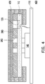
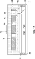
FIG. 17 , compared with theautomotive ornament 700 of the embodiment ofFIG. 7 , an automotive ornament 7 of the embodiment further includes anadhesive layer 7b disposed between asurface decoration layer 630 and thesubstrate 110, but the invention is not limited thereto. - In the embodiment, the
substrate 110 and thecircuit board 170 may further include a semi-light-transmitting diffuser Id there between, where the semi-light-transmitting diffuser Id implements refraction through concavity and convexity, and may achieve a gradation effect through printing processing, but the invention is not limited thereto. - Referring to
FIG. 18 , compared with the automotive ornament 7 of the embodiment ofFIG. 17 , atexture layer 8a of an automotive ornament 8 of the embodiment is disposed between asubstrate 8b and thecircuit board 170, and an adhesive layer is not included, but the invention is not limited thereto. - Referring to
FIG. 19 , compared with theautomotive ornament 11 of the embodiment ofFIG. 11 , anautomotive ornament 9 of the embodiment does not include an adhesive layer, and asurface decoration layer 9a is a four-layer structure, where the four-layer structure sequentially includes a high and low temperature hot melt gel film, a semi-light-transmitting/light-transmitting gel film (PVC/PU/ TPU), a hot melt gel layer and a semi-light-transmitting/light-transmitting gel film (PVC/PU/TPU) from inside to outside, but the invention is not limited thereto. - In some embodiments, the
surface decoration layer 9a may not include the high and low temperature hot melt gel film, and when thesurface decoration layer 9a includes the high and low temperature hot melt gel film, following heating methods are available. A first method may be to use infrared heating (permeable heating) to heat together with a front side (appearance)/a back side/front and back sides (double-sided) of thesurface decoration layer 9a, while other parts of materials may be heated or not heated and may be sprayed or not sprayed. A second method may be ceramic heating (a ceramic plate heating requires high temperature since permeable heating is inapplicable), and such method requires front heating, while other parts of materials may be heated or not heated and may be sprayed or not sprayed. A third method may be to use a heating tube hot air to heat together with a front side (appearance)/a back side/front and back sides (double-sided) of thesurface decoration layer 9a, while other parts of materials may be heated or not heated and may be sprayed or not sprayed. - Referring to
FIG. 20 , compared with theautomotive ornament 9 of the embodiment ofFIG. 19 , atexture layer 91a of anautomotive ornament 91 of the embodiment is disposed between asubstrate 91b and thecircuit board 170. In addition, a pressure sensing element 91c of theautomotive ornament 91 sequentially penetrates through thesubstrate 91b and thetexture layer 91a, but the invention is not limited thereto. - In addition, in the above embodiments, the
texture layer 2a, thetexture layer 6a, thetexture layer 7a, thetexture layer 8a, thetexture layer 91a, and thetexture layer 880 may all be similar to thetexture layer 280, i.e., the above texture layers may all be black paint or ink with a shielding function formed by a spraying process, and the texture patterns in the texture layers may all be formed in the pattern layer by laser engraving or multi-layer coating printing (no laser engraving). In addition, after laser engraving, vacuum sputtering may be performed to achieve a high-gloss metallic feel. On the other hand, the above-mentioned texture layer may be semi-light-transmitting, opaque, transparent, or a multi-layer stacked structure, and the texture layer is not limited to single-layer coating or printing, and may optionally include multiple layers. - Referring to
FIG. 21 , compared with theautomotive ornament 2 of the embodiment ofFIG. 12 , asurface decoration layer 92a of anautomotive ornament 92 of the embodiment is light-transmitting leather of a single-layer structure, and thesurface decoration layer 92a and theadhesive layer 1a further include adiffuser 92b there between, where thediffuser 92b implements refraction through concavity and convexity, but the invention is not limited thereto. -
FIG. 22A to FIG. 22D are schematic partial cross-sectional views of a part of a manufacturing method of an automotive ornament according to some embodiments of the invention. - In some embodiments, the manufacturing process of an automotive ornament D may include the following steps. Referring to
FIG. 22A , first, the surface decoration layer S with an adhesive layer (not shown) on the back after cutting may be heated to make the adhesive layer sticky. Referring toFIG. 22B , OMD molding (TOM process) of in-mold injection (vacuum suction positioning) is used, where the OMD molding method may be injection molding through a material A (such as the component wrapped by the surface decoration layer in the above embodiment), laser engraving after front coating, placing the pressure sensing element, placing a table, mold closing vacuuming and heating to soften, pressing molding to finally form a product, laser cutting of the remaining material, transfer printing/laser engraving of pressure sensing marks, etc. Referring toFIG. 22C , a leather wrapping machine is used to implement a wrapping operation of the surface decoration layer S. Referring toFIG. 22D , finally, the automotive ornament D wrapped with the surface decoration layer S is formed. - Moreover, in the above manufacturing method, the surface decoration layer S in
FIG. 22A may also have no adhesive layer on the back side, and the same process is used to form the automotive ornament. -
FIG. 23A to FIG. 23D are schematic partial cross-sectional views of a part of a manufacturing method of an automotive ornament according to some other embodiments of the invention. - In some other embodiments, the manufacturing process of the automotive ornament D may include the following steps. Referring to
FIG. 23A , first, the surface decoration layer S with an adhesive layer (not shown) on the back after cutting may be heated to make the adhesive layer sticky, and laser engraving and placing the pressure sensing element are performed after front coating of the material A (such as the component wrapped by the surface decoration layer in the above embodiment). Referring toFIG. 23B , the surface decoration layer S is positioned on an imitation fixture M. Referring toFIG. 23C , manual wrapping is performed to implement the wrapping operation of the surface decoration layer S. Referring toFIG. 23D , finally, the automotive ornament D wrapped with the surface decoration layer S is formed. - In addition, in the above-mentioned manufacturing method, the surface decoration layer S in
FIG. 23A may also have no adhesive layer on the back surface, and after the laser engraving on the front surface, a transparent paint may be sprayed, and then the same process is adopted to form the automotive ornament. - It should be noted that the invention is not limited to the aspects of the aforementioned embodiments, and the aspects of the aforementioned embodiments may be arbitrarily matched, and similar films may adopt similar materials. In addition, the aforementioned manufacturing method and TOM process are all exemplary descriptions, and the invention is not limited thereto. The above steps and processes may be selected, arranged and matched according to actual design requirements, and other suitable steps and processes may be added according to actual design requirements, as long as the surface decoration layer wraps the substrate, the surface decoration layer covers the pressure sensing element, the pressure sensing element is electrically connected to the light-emitting element through the circuit board, and pressure sensing of the pressure sensing element causes the light-emitting element to emit light, it is consider to be within the protection scope of the invention.
- In summary, due to the light-transmitting property of the surface decoration layer, the substrate of the automotive ornament of the invention may have an improved visual effect through wrapping of the surface decoration layer. In addition, as the surface decoration layer covers the pressure sensing element, the pressure sensing element is electrically connected to the light-emitting element through the circuit board, and the pressure sensing of the pressure sensing element causes the light-emitting element to emit light, the automotive ornament of the invention has both practicality and improved visual effect.
- It will be apparent to those skilled in the art that various modifications and variations can be made to the disclosed embodiments without departing from the scope or spirit of the invention. In view of the foregoing, it is intended that the invention covers modifications and variations provided they fall within the scope of the following claims and their equivalents.
Claims (10)
- An automotive ornament (1, 2, 3, 4, 5, 6, 7, 8, 9, 91, 92, 10, 100, 200, 300, 400, 500, 600, 700, 800, 900, D), comprising:a circuit board (170);a substrate (2b, 4b, 6b, 8b, 91b, 11, 110), disposed on the circuit board (170);a light-emitting element (14, 140), disposed between the circuit board (170) and the substrate (2b, 4b, 6b, 8b, 91b, 11, 110), and the light-emitting element (14, 140) being electrically connected to the circuit board (170);a surface decoration layer (3b, 9a, 92a, 13, 130, 230, 430, 630, S), wrapping the substrate (2b, 4b, 6b, 8b, 91b, 11, 110); anda pressure sensing element (12, 120), wherein the surface decoration layer (3b, 9a, 92a, 13, 130, 230, 430, 630, S) covers the pressure sensing element (12, 120), the pressure sensing element (12, 120) is electrically connected to the light-emitting element (14, 140) through the circuit board (170), and pressure sensing of the pressure sensing element (12, 120) causes the light-emitting element (14, 140) to emit light, vibrate, or feedback sound.
- The automotive ornament (1, 2, 3, 4, 5, 6, 7, 8, 9, 91, 92, 10, 100, 200, 300, 400, 500, 600, 700, 800, 900, D) as claimed in claim 1, further comprising an adhesive layer (1a, 7b, 150) disposed between the surface decoration layer (3b, 9a, 92a, 13, 130, 230, 430, 630, S) and the substrate (2b, 4b, 6b, 8b, 91b, 11, 110).
- The automotive ornament (1, 2, 3, 4, 5, 6, 7, 8, 9, 91, 92, 10, 100, 200, 300, 400, 500, 600, 700, 800, 900, D) as claimed in claim 1, wherein the light-emitting element (14, 140) is a micro light-emitting element (14, 140) in the circuit board (170).
- The automotive ornament (1, 2, 3, 4, 5, 6, 7, 8, 9, 91, 92, 10, 100, 200, 300, 400, 500, 600, 700, 800, 900, D) as claimed in claim 1, wherein the pressure sensing element (12, 120) penetrates through the substrate (2b, 4b, 6b, 8b, 91b, 11, 110).
- The automotive ornament (1, 2, 3, 4, 5, 6, 7, 8, 9, 91, 92, 10, 100, 200, 300, 400, 500, 600, 700, 800, 900, D) as claimed in claim 1, further comprising a texture layer (2a, 6a, 7a, 8a, 91a, 280, 880), wherein the texture layer (2a, 6a, 7a, 8a, 91a, 280, 880) comprises a texture pattern (3a, 282), the surface decoration layer (3b, 9a, 92a, 13, 130, 230, 430, 630, S) covers the texture pattern (3a, 282), and the texture layer (2a, 6a, 7a, 8a, 91a, 280, 880) has a stretching degree less than that of the surface decoration layer (3b, 9a, 92a, 13, 130, 230, 430, 630, S).
- The automotive ornament (1, 2, 3, 4, 5, 6, 7, 8, 9, 91, 92, 10, 100, 200, 300, 400, 500, 600, 700, 800, 900, D) as claimed in claim 5, wherein:the texture layer (2a, 6a, 7a, 8a, 91a, 280, 880) is disposed between the substrate (2b, 4b, 6b, 8b, 91b, 11, 110) and the surface decoration layer (3b, 9a, 92a, 13, 130, 230, 430, 630, S); orthe texture layer (2a, 6a, 7a, 8a, 91a, 280, 880) is disposed between the substrate (2b, 4b, 6b, 8b, 91b, 11, 110) and the circuit board (170).
- The automotive ornament (1, 2, 3, 4, 5, 6, 7, 8, 9, 91, 92, 10, 100, 200, 300, 400, 500, 600, 700, 800, 900, D) as claimed in claim 1, wherein the surface decoration layer (3b, 9a, 92a, 13, 130, 230, 430, 630, S) comprises light-transmitting leather, semi-light-transmitting leather, opaque leather, gel film, imitation wood veneer, real wood veneer, leather with color gradation, or gel film with color gradation.
- The automotive ornament (1, 2, 3, 4, 5, 6, 7, 8, 9, 91, 92, 10, 100, 200, 300, 400, 500, 600, 700, 800, 900, D) as claimed in claim 1, further comprising a light-blocking bracket (390) surrounding a light-emitting area (R) of the light-emitting element (14, 140).
- The automotive ornament (1, 2, 3, 4, 5, 6, 7, 8, 9, 91, 92, 10, 100, 200, 300, 400, 500, 600, 700, 800, 900, D) as claimed in claim 1, further comprising a light-transmitting mark (16), wherein a ray emitted by the light-emitting element (14, 140) exits the surface decoration layer (3b, 9a, 92a, 13, 130, 230, 430, 630, S) through the light-transmitting mark (16) to display the light-transmitting mark (16).
- A manufacturing method of an automotive ornament (1, 2, 3, 4, 5, 6, 7, 8, 9, 91, 92, 10, 100, 200, 300, 400, 500, 600, 700, 800, 900, D), comprising:providing a substrate (2b, 4b, 6b, 8b, 91b, 11, 110), wherein the substrate (2b, 4b, 6b, 8b, 91b, 11, 110) has a first surface (11a, 110a) and a second surface (11b, 110b) opposite to the first surface (11a, 110a);disposing a pressure sensing element (12, 120) in the substrate (2b, 4b, 6b, 8b, 91b, 11, 110);stretching a surface decoration layer (3b, 9a, 92a, 13, 130, 230, 430, 630, S), so that the surface decoration layer (3b, 9a, 92a, 13, 130, 230, 430, 630, S) at least wraps the substrate (2b, 4b, 6b, 8b, 91b, 11, 110); anddisposing a circuit board (170) on the second surface (11b, 110b), wherein the circuit board (170) has a light-emitting element (14, 140), the pressure sensing element (12, 120) is electrically connected to the light-emitting element (14, 140) through the circuit board (170), and the light-emitting element (14, 140) is made to emit light, vibrate, or feedback sound through pressure sensing of the pressure sensing element (12, 120).
Applications Claiming Priority (1)
| Application Number | Priority Date | Filing Date | Title |
|---|---|---|---|
| TW109134299A TW202214462A (en) | 2020-09-30 | 2020-09-30 | Automotive ornament and manufacturing method thereof |
Publications (1)
| Publication Number | Publication Date |
|---|---|
| EP3978293A1 true EP3978293A1 (en) | 2022-04-06 |
Family
ID=78086977
Family Applications (1)
| Application Number | Title | Priority Date | Filing Date |
|---|---|---|---|
| EP21194952.4A Withdrawn EP3978293A1 (en) | 2020-09-30 | 2021-09-06 | Automotive ornament and manufacturing method thereof |
Country Status (5)
| Country | Link |
|---|---|
| US (1) | US20220097627A1 (en) |
| EP (1) | EP3978293A1 (en) |
| JP (1) | JP2022058199A (en) |
| CN (1) | CN114312596A (en) |
| TW (1) | TW202214462A (en) |
Families Citing this family (1)
| Publication number | Priority date | Publication date | Assignee | Title |
|---|---|---|---|---|
| CN114987021B (en) * | 2022-05-26 | 2023-11-21 | 东风柳州汽车有限公司 | Light-transmitting plate and automobile interior trim part |
Citations (3)
| Publication number | Priority date | Publication date | Assignee | Title |
|---|---|---|---|---|
| FR3040337A1 (en) * | 2015-08-28 | 2017-03-03 | Faurecia Interieur Ind | CONTROL PANEL FOR A VEHICLE AND METHOD FOR REALIZING THE SAME |
| US20180251032A1 (en) * | 2017-03-06 | 2018-09-06 | Lg Electronics Inc. | User interface apparatus for vehicle, method of manufacturing user interface apparatus, and vehicle |
| US20200139814A1 (en) * | 2016-07-11 | 2020-05-07 | Shanghai Yanfeng Jinqiao Automotive Trim Systems Co. Ltd. | Vehicle interior component |
Family Cites Families (3)
| Publication number | Priority date | Publication date | Assignee | Title |
|---|---|---|---|---|
| US10275040B2 (en) * | 2017-08-18 | 2019-04-30 | Apple Inc. | Low-travel illuminated key mechanism |
| JP2019040802A (en) * | 2017-08-28 | 2019-03-14 | ダイキョーニシカワ株式会社 | Vehicle switch device |
| JP2020035156A (en) * | 2018-08-29 | 2020-03-05 | 富士通コンポーネント株式会社 | Touch panel device |
-
2020
- 2020-09-30 TW TW109134299A patent/TW202214462A/en unknown
- 2020-12-10 US US17/117,117 patent/US20220097627A1/en not_active Abandoned
-
2021
- 2021-09-06 EP EP21194952.4A patent/EP3978293A1/en not_active Withdrawn
- 2021-09-06 CN CN202111038320.2A patent/CN114312596A/en not_active Withdrawn
- 2021-09-06 JP JP2021144512A patent/JP2022058199A/en active Pending
Patent Citations (3)
| Publication number | Priority date | Publication date | Assignee | Title |
|---|---|---|---|---|
| FR3040337A1 (en) * | 2015-08-28 | 2017-03-03 | Faurecia Interieur Ind | CONTROL PANEL FOR A VEHICLE AND METHOD FOR REALIZING THE SAME |
| US20200139814A1 (en) * | 2016-07-11 | 2020-05-07 | Shanghai Yanfeng Jinqiao Automotive Trim Systems Co. Ltd. | Vehicle interior component |
| US20180251032A1 (en) * | 2017-03-06 | 2018-09-06 | Lg Electronics Inc. | User interface apparatus for vehicle, method of manufacturing user interface apparatus, and vehicle |
Also Published As
| Publication number | Publication date |
|---|---|
| JP2022058199A (en) | 2022-04-11 |
| US20220097627A1 (en) | 2022-03-31 |
| CN114312596A (en) | 2022-04-12 |
| TW202214462A (en) | 2022-04-16 |
Similar Documents
| Publication | Publication Date | Title |
|---|---|---|
| CN110178450B (en) | Illumination structure and related manufacturing method | |
| US10827609B2 (en) | Ecological multilayer structure for hosting electronics and related method of manufacture | |
| EP1914067B1 (en) | Method for fabricating a curved casing formed from thermoplastic resin and film having a polarizing effect | |
| KR20170102220A (en) | Multilayer structure for accommodating electronics and related method of manufacture | |
| EP3978293A1 (en) | Automotive ornament and manufacturing method thereof | |
| US11906774B2 (en) | Optically functionally multilayer structure suitable for large area illumination and related method of manufacture | |
| US20220097628A1 (en) | Automotive ornament and manufacturing method thereof | |
| TW202311084A (en) | Automotive ornament and manufacturing method thereof | |
| US11817534B1 (en) | Optically functional multilayer structure and related method of manufacture | |
| US20240003516A1 (en) | Optically functional multilayer structure and related method of manufacture | |
| US11914184B2 (en) | Optically functional multilayer structure suitable for large area illumination and related method of manufacture | |
| TW202416504A (en) | Optically functional multilayer structure and related method of manufacture | |
| CN214587745U (en) | Flat panel display device for displaying dynamic decoration and display device array | |
| CN112331083A (en) | Flat panel display device, display device array and method of manufacturing display device | |
| CN113954474A (en) | Light-transmitting material for surface decoration, preparation method and automobile decoration |
Legal Events
| Date | Code | Title | Description |
|---|---|---|---|
| PUAI | Public reference made under article 153(3) epc to a published international application that has entered the european phase |
Free format text: ORIGINAL CODE: 0009012 |
|
| STAA | Information on the status of an ep patent application or granted ep patent |
Free format text: STATUS: REQUEST FOR EXAMINATION WAS MADE |
|
| 17P | Request for examination filed |
Effective date: 20210906 |
|
| AK | Designated contracting states |
Kind code of ref document: A1 Designated state(s): AL AT BE BG CH CY CZ DE DK EE ES FI FR GB GR HR HU IE IS IT LI LT LU LV MC MK MT NL NO PL PT RO RS SE SI SK SM TR |
|
| RBV | Designated contracting states (corrected) |
Designated state(s): AL AT BE BG CH CY CZ DE DK EE ES FI FR GB GR HR HU IE IS IT LI LT LU LV MC MK MT NL NO PL PT RO RS SE SI SK SM TR |
|
| STAA | Information on the status of an ep patent application or granted ep patent |
Free format text: STATUS: THE APPLICATION HAS BEEN WITHDRAWN |
|
| 18W | Application withdrawn |
Effective date: 20221201 |