EP3977060B1 - Einstellelement für messvorrichtungen - Google Patents
Einstellelement für messvorrichtungen Download PDFInfo
- Publication number
- EP3977060B1 EP3977060B1 EP20814918.7A EP20814918A EP3977060B1 EP 3977060 B1 EP3977060 B1 EP 3977060B1 EP 20814918 A EP20814918 A EP 20814918A EP 3977060 B1 EP3977060 B1 EP 3977060B1
- Authority
- EP
- European Patent Office
- Prior art keywords
- measuring device
- adjustment
- proximal
- adjusting
- target area
- Prior art date
- Legal status (The legal status is an assumption and is not a legal conclusion. Google has not performed a legal analysis and makes no representation as to the accuracy of the status listed.)
- Active
Links
Images








Classifications
-
- G—PHYSICS
- G01—MEASURING; TESTING
- G01D—MEASURING NOT SPECIALLY ADAPTED FOR A SPECIFIC VARIABLE; ARRANGEMENTS FOR MEASURING TWO OR MORE VARIABLES NOT COVERED IN A SINGLE OTHER SUBCLASS; TARIFF METERING APPARATUS; MEASURING OR TESTING NOT OTHERWISE PROVIDED FOR
- G01D3/00—Indicating or recording apparatus with provision for the special purposes referred to in the subgroups
- G01D3/02—Indicating or recording apparatus with provision for the special purposes referred to in the subgroups with provision for altering or correcting the law of variation
-
- G—PHYSICS
- G01—MEASURING; TESTING
- G01D—MEASURING NOT SPECIALLY ADAPTED FOR A SPECIFIC VARIABLE; ARRANGEMENTS FOR MEASURING TWO OR MORE VARIABLES NOT COVERED IN A SINGLE OTHER SUBCLASS; TARIFF METERING APPARATUS; MEASURING OR TESTING NOT OTHERWISE PROVIDED FOR
- G01D11/00—Component parts of measuring arrangements not specially adapted for a specific variable
- G01D11/30—Supports specially adapted for an instrument; Supports specially adapted for a set of instruments
-
- G—PHYSICS
- G01—MEASURING; TESTING
- G01K—MEASURING TEMPERATURE; MEASURING QUANTITY OF HEAT; THERMALLY-SENSITIVE ELEMENTS NOT OTHERWISE PROVIDED FOR
- G01K1/00—Details of thermometers not specially adapted for particular types of thermometer
- G01K1/08—Protective devices, e.g. casings
-
- G—PHYSICS
- G01—MEASURING; TESTING
- G01K—MEASURING TEMPERATURE; MEASURING QUANTITY OF HEAT; THERMALLY-SENSITIVE ELEMENTS NOT OTHERWISE PROVIDED FOR
- G01K15/00—Testing or calibrating of thermometers
- G01K15/005—Calibration
-
- G—PHYSICS
- G01—MEASURING; TESTING
- G01L—MEASURING FORCE, STRESS, TORQUE, WORK, MECHANICAL POWER, MECHANICAL EFFICIENCY, OR FLUID PRESSURE
- G01L19/00—Details of, or accessories for, apparatus for measuring steady or quasi-steady pressure of a fluent medium insofar as such details or accessories are not special to particular types of pressure gauges
- G01L19/02—Arrangements for preventing, or for compensating for, effects of inclination or acceleration of the measuring device; Zero-setting means
-
- G—PHYSICS
- G01—MEASURING; TESTING
- G01L—MEASURING FORCE, STRESS, TORQUE, WORK, MECHANICAL POWER, MECHANICAL EFFICIENCY, OR FLUID PRESSURE
- G01L19/00—Details of, or accessories for, apparatus for measuring steady or quasi-steady pressure of a fluent medium insofar as such details or accessories are not special to particular types of pressure gauges
- G01L19/14—Housings
- G01L19/147—Details about the mounting of the sensor to support or covering means
-
- G—PHYSICS
- G01—MEASURING; TESTING
- G01L—MEASURING FORCE, STRESS, TORQUE, WORK, MECHANICAL POWER, MECHANICAL EFFICIENCY, OR FLUID PRESSURE
- G01L27/00—Testing or calibrating of apparatus for measuring fluid pressure
- G01L27/002—Calibrating, i.e. establishing true relation between transducer output value and value to be measured, zeroing, linearising or span error determination
-
- G—PHYSICS
- G01—MEASURING; TESTING
- G01D—MEASURING NOT SPECIALLY ADAPTED FOR A SPECIFIC VARIABLE; ARRANGEMENTS FOR MEASURING TWO OR MORE VARIABLES NOT COVERED IN A SINGLE OTHER SUBCLASS; TARIFF METERING APPARATUS; MEASURING OR TESTING NOT OTHERWISE PROVIDED FOR
- G01D11/00—Component parts of measuring arrangements not specially adapted for a specific variable
- G01D11/24—Housings ; Casings for instruments
- G01D11/245—Housings for sensors
Definitions
- the present disclosure relates to measuring devices (e.g., pressure or temperature measuring devices) and methods for adjusting one or more features (e.g., offset and/or span) associated with measuring devices and, more particularly, to sealed measuring devices (e.g., sealed signal conditioning devices, such as sealed pressure transducers or transmitters) having adjustment members (e.g., magnet members) that allow a user to adjust one or more features (e.g., offset and/or span) of the sealed measuring devices.
- sealed measuring devices e.g., sealed signal conditioning devices, such as sealed pressure transducers or transmitters
- adjustment members e.g., magnet members
- Measuring devices such as instruments and signal conditioning devices used for measuring pressure or temperature, have innumerable uses in industry.
- pressure measuring devices e.g., transducers, transmitters, digital gauges, etc.
- pressure measuring devices configured to measure the pressure of process media are well known.
- Measuring devices are useful in a myriad of different environments for commercial and industrial applications. Typically, pressure measuring devices measure pressure and provide an indication of the value.
- US2003/158681 discloses a method for calibration of a sensor wherein the sensor is arranged in a predetermined position, an equalizing unit is connected to the sensor, data necessary for calibration are determined, and the determined calibration data are stored permanently in a storage medium.
- the present disclosure provides advantageous measuring devices (e.g., pressure or temperature measuring devices), and improved systems and methods for adjusting one or more features (e.g., offset and/or span) associated with measuring devices. More particularly, the present disclosure provides improved sealed measuring devices (e.g., sealed signal conditioning devices, such as sealed pressure transducers or transmitters) having adjustment members (e.g., magnet members) that allow a user to adjust one or more features (e.g., offset and/or span) of the sealed measuring devices (e.g., without breaching the seals of the measuring device).
- sealed signal conditioning devices such as sealed pressure transducers or transmitters
- adjustment members e.g., magnet members
- the measuring devices include an adjustment member that allows a user to make adjustments to one or more features of the measuring devices.
- a sealed pressure transducer can include an magnet member that allows a user to make fine (precision) adjustments of output offset and/or span (e.g., in the field), without breaching the enclosure or housing of the measuring device.
- the present disclosure provides for a method for adjusting a measuring system including operating a process; mounting a measuring device with respect to the process for measuring a parameter associated with the process; applying power to the measuring device; positioning an adjustment member against or proximal to a target area of the measuring device and within a pre-determined period of time after applying power to the measuring device to place the measuring device in an adjustment mode that enables subsequent adjustment of one or more features of the measuring device via subsequent positioning of the adjustment member against or proximal to the target area; subsequently positioning the adjustment member against or proximal to the target area while the measuring device is in the adjustment mode to adjust one or more features of the measuring device.
- the present disclosure also provides for a method for adjusting a measuring system wherein the process is operated under pressure; and wherein the measuring device is a sealed pressure measuring device.
- the present disclosure also provides for a method for adjusting a measuring system wherein the measuring device is a pressure measuring device or a temperature measuring device.
- the present disclosure also provides for a method for adjusting a measuring system wherein the measuring device is a pressure transducer or a pressure transmitter.
- the present disclosure also provides for a method for adjusting a measuring system wherein the measuring device is a sealed signal conditioning device.
- the present disclosure also provides for a method for adjusting a measuring system wherein the adjustment member is a magnet member.
- the present disclosure also provides for a method for adjusting a measuring system wherein the measuring device includes a sensing element; and wherein the sensing element is a magnetically sensitive logic input device.
- the present disclosure also provides for a method for adjusting a measuring system wherein the pre-determined period of time after applying power to the measuring device is about 30 seconds or less.
- the present disclosure also provides for a method for adjusting a measuring system wherein the adjustment of the one or more features of the measuring device includes adjusting a digital or analog output of the measuring device.
- the present disclosure also provides for a method for adjusting a measuring system wherein the adjustment of the one or more features of the measuring device includes adjusting an offset or span of the measuring device.
- the present disclosure also provides for a method for adjusting a measuring system wherein the adjustment of the one or more features of the measuring device occurs without breaching an enclosure or housing of the measuring device.
- the present disclosure also provides for a method for adjusting a measuring system wherein positioning the adjustment member against or proximal to the target area to place the measuring device in the adjustment mode requires a pre-determined sequenced code or placement rhythm of the adjustment member against or proximal to the target area to place the measuring device in the adjustment mode.
- the present disclosure also provides for a method for adjusting a measuring system wherein the pre-determined sequenced code or placement rhythm includes two or more knocks or placements of the adjustment member against or proximal to the target area to place the measuring device in the adjustment mode.
- the present disclosure also provides for a method for adjusting a measuring system wherein the measuring device sends a first signal and a second signal prior to entering the adjustment mode.
- the present disclosure also provides for a method for adjusting a measuring system wherein the adjustment mode switches between operating or functioning on adjusting a first feature of the measuring device, and operating or functioning on adjusting a second feature of the measuring device, depending on the numerical or percentage value of the parameter of the process that is applied to the measuring device.
- the present disclosure also provides for a method for adjusting a measuring system wherein the process is operated under pressure; wherein adjusting the first feature includes adjusting an offset of the measuring device; and wherein adjusting the second feature includes adjusting a span of the measuring device.
- the present disclosure also provides for a method for adjusting a measuring system wherein the adjustment mode switches between adjusting the first and second features depending on the percent of pressure that is applied to the measuring device.
- the present disclosure also provides for a method for adjusting a measuring system wherein when the measuring device is operated in a first parameter range of the process, a first feature of the measuring device can be adjusted by subsequently positioning the adjustment member against or proximal to the target area; and wherein when the measuring device is operated in a second parameter range of the process, a second feature of the measuring device can be adjusted by subsequently positioning the adjustment member against or proximal to the target area.
- the present disclosure also provides for a method for adjusting a measuring system wherein the process is operated under pressure; wherein adjusting the first feature includes adjusting an offset of the measuring device; and wherein adjusting the second feature includes adjusting a span of the measuring device.
- the present disclosure also provides for a method for adjusting a measuring system wherein the first parameter range of the process is from about plus 10% pressure to about minus 10% pressure that is applied to the measuring device; and wherein the second parameter range of the process is about 40% or greater pressure that is applied to the measuring device.
- the present disclosure also provides for a method for adjusting a measuring system wherein each subsequent positioning of the adjustment member against or proximal to the target area while the measuring device is in the adjustment mode incrementally adjusts one or more features of the measuring device.
- the present disclosure also provides for a method for adjusting a measuring system wherein after a plurality of positive incremental adjustments of the one or more features reaches an upper adjustment limit, the next subsequent positioning of the adjustment member against or proximal to the target area sends the next incremental adjustment to a lower adjustment limit, and then the next subsequent adjustment increments positively from the lower adjustment limit.
- the present disclosure also provides for a method for adjusting a measuring system wherein after the measuring device is in the adjustment mode and after a time-frame of inactivity of positioning the adjustment member against or proximal to the target area, the measuring device enters a non-adjustment mode.
- the present disclosure also provides for a method for adjusting a measuring system wherein the measuring device sends a first signal and a second signal after entering the non-adjustment mode.
- the present disclosure also provides for a method for adjusting a measuring system including operating a process; mounting a measuring device with respect to the process for measuring a parameter associated with the process; applying power to the measuring device; positioning an adjustment member against or proximal to a target area of the measuring device and within a pre-determined period of time after applying power to the measuring device to place the measuring device in an adjustment mode that enables subsequent adjustment of one or more features of the measuring device via subsequent positioning of the adjustment member against or proximal to the target area; subsequently positioning the adjustment member against or proximal to the target area while the measuring device is in the adjustment mode to adjust one or more features of the measuring device; wherein the measuring device is a sealed signal conditioning device; wherein the measuring device sends at least a first signal prior to entering the adjustment mode; wherein when the measuring device is operated in a first parameter range of the process, a first feature of the measuring device can be adjusted by subsequently positioning the adjustment member against or proximal to the target area; wherein when the measuring device is operated in a second
- the present disclosure also provides for a method for adjusting a pressure measuring system including operating a process under pressure; mounting a pressure measuring device with respect to the process for measuring pressure associated with the process; applying power to the pressure measuring device; positioning a magnet member against or proximal to a target area of the pressure measuring device and within a pre-determined period of time after applying power to the pressure measuring device to place the pressure measuring device in an adjustment mode that enables subsequent adjustment of offset or span of the pressure measuring device via subsequent positioning of the magnet member against or proximal to the target area; subsequently positioning the magnet member against or proximal to the target area while the pressure measuring device is in the adjustment mode to adjust offset or span of the measuring device; wherein positioning the magnet member against or proximal to the target area to place the pressure measuring device in the adjustment mode requires a pre-determined sequenced code or placement rhythm of the magnet member against or proximal to the target area to place the pressure measuring device in the adjustment mode; wherein the adjustment of the offset or span of the pressure measuring device occurs without breaching an enclosure or housing
- the exemplary embodiments disclosed herein are illustrative of advantageous measuring devices (e.g., pressure or temperature measuring devices), and systems of the present disclosure and adjustment methods/techniques thereof. It should be understood, however, that the disclosed embodiments are merely exemplary of the present disclosure, which may be embodied in various forms. Therefore, details disclosed herein with reference to exemplary measuring devices/adjustment methods and associated processes/techniques of assembly and use are not to be interpreted as limiting, but merely as the basis for teaching one skilled in the art how to make and use the advantageous measuring devices/methods and/or alternative measuring devices/methods of the present disclosure.
- the present disclosure provides improved measuring devices (e.g., pressure or temperature measuring devices), and improved systems and methods for adjusting one or more features (e.g., offset and/or span) associated with measuring devices. More particularly, the present disclosure provides advantageous sealed measuring devices (e.g., sealed signal conditioning devices, such as sealed pressure transducers or transmitters) having adjustment members (e.g., magnet members) that allow a user to adjust one or more features (e.g., offset and/or span) of the sealed measuring devices.
- sealed signal conditioning devices such as sealed pressure transducers or transmitters
- adjustment members e.g., magnet members
- the present disclosure provides for improved systems/methods for adjusting one or more features (e.g., offset and/or span) of measuring devices (e.g., sealed signal conditioning devices, such as sealed pressure transducers or transmitters) by utilizing adjustment members (e.g., magnet members) to adjust the offset and/or span of the measuring devices, thereby providing significant operational, manufacturing and commercial advantages as a result.
- measuring devices e.g., sealed signal conditioning devices, such as sealed pressure transducers or transmitters
- adjustment members e.g., magnet members
- FIG. 1 there is illustrated a measuring device 10 depicting an embodiment of the present disclosure.
- Exemplary measuring device 10 takes the form of a pressure or temperature measuring device 10 or the like, although the present disclosure is not limited thereto.
- exemplary measuring device 10 takes the form of a sealed measuring device 10 (e.g., a sealed signal conditioning device 10, such as a sealed pressure transducer 10 or transmitter 10).
- Measuring device 10 is configured and dimensioned to be mounted with respect to a process for measuring a parameter associated with the process (e.g., a pressure transducer/transmitter 10 configured to measure the pressure of process media or the like).
- measuring device 10 e.g., sealed pressure transducer 10) includes an adjustment member 14 (e.g., magnet member 14) that allows a user to make adjustments to one or more features (e.g., offset and/or span) of measuring device 10.
- adjustment member 14 e.g., magnet member 14
- features e.g., offset and/or span
- sealed pressure transducer 10 can include an adjustment member 14 (e.g., magnet member 14) that allows a user to make fine (precision) adjustments of output offset and/or span (e.g., in the field), without breaching the enclosure or housing 12 of the measuring device 10.
- adjustment member 14 e.g., magnet member 14
- output offset and/or span e.g., in the field
- a magnet member 14 e.g., a small magnet member 14, similar to one located on the end of a screwdriver
- tapping/contacting or placing the magnet member 14 against or proximal to the housing 12 in a designated or target area of the housing 12 within a pre-determined period of time e.g., within about 30 seconds; within about 10 seconds; etc.
- the output e.g., analog and/or digital output
- the output of the measuring device 10 will increment in (small) steps via sensing element 16 of measuring device 10 (e.g., via a reed switch 16 centrally located within measuring device 10) via subsequent taps/knocks/placement of the magnet member 14 against or proximal to the housing 12.
- the output of the measuring device 10 will thereafter automatically progress and advance in speed if the magnet member 14 is held in place (e.g., greater than 2 or 3 seconds; etc.) against or proximal to the designated/target area of the housing 12.
- adjustment member 14 can take the form of a rotating ring 14 (e.g., around the housing 12) or magnetic wheel 14 or the like, and such adjustment member 14 could be used to facilitate alternating magnetic pulses (e.g., replicating taps/knocks/placement of the adjustment member 14 against or proximal to the housing 12).
- the sensing element 16 is a magnetically sensitive (digital) logic input device (e.g., a magnetic switch 16, but can be replaced or enhanced with a Hall effect or GMR sensor 16 for a more complex magnetic input method).
- a magnetically sensitive (digital) logic input device e.g., a magnetic switch 16, but can be replaced or enhanced with a Hall effect or GMR sensor 16 for a more complex magnetic input method.
- multiple sensing elements 16 of measuring device 10 can provide additional remote logic inputs for added function or communication of input.
- Hall effect sensors 16 or GMR (giant magnetoresistance) devices 16 can substitute (as alternatives to a reed switch 16) to provide proportional (not just logic) input - even facilitating a magnetic communication input to serve as a heuristic input for adjustment or configuration.
- sensing element 16 can also take the form of: a tactile switch (e.g., without magnet member 14 - manually operated); a percussive sensor (e.g., piezoelectric or microphone) - to detect "taps" or the like on/near the housing 12; a position switch; an optical switch/sensor or other magnetic sensors such as Wiegand effect device, GMR (giant magnetoresistance), or Hall Effect sensors 16.
- a tactile switch e.g., without magnet member 14 - manually operated
- a percussive sensor e.g., piezoelectric or microphone
- security for the measuring device 10 can be provided by requiring a fixed or pre-determined sequenced code or knocking/tapping/placement rhythm/sequence of the adjustment member 14 (e.g., magnet member 14) against or proximal to the housing 12 to enable the subsequent adjustment of offset and/or span of measuring device 10 via magnet member 14 (e.g., two knocks/taps/placement of the magnet member 14 against or proximal to housing 12; three knocks/taps/placement of the magnet member 14 against or proximal to housing 12; a plurality of certain knocks/taps/placement of the magnet member 14 against or proximal to housing 12; etc.).
- magnet member 14 e.g., two knocks/taps/placement of the magnet member 14 against or proximal to housing 12; three knocks/taps/placement of the magnet member 14 against or proximal to housing 12; a plurality of certain knocks/taps/placement of the magnet member 14 against or proximal to housing
- Such a requirement for the fixed or pre-determined sequenced code or knocking/tapping/placement rhythm of the magnet member 14 against or proximal to the housing 12 to enable the subsequent adjustment of one or more features of the measuring device 10 (e.g., offset and/or span) can prevent inadvertent or unauthorized calibration or adjustment of the measuring device 10.
- a measuring device 10 e.g., pressure transducer/transmitter
- a parameter e.g., pressure
- a magnet member 14 can be tapped or contacted/placed/positioned (e.g., using the correct knock-on or tapping security code/rhythm/sequence) against or proximal to the housing 12 in a pre-determined or target area of the housing 12 (e.g., indicated on a label or the like of the housing) to place the measuring device into an adjustment mode that enables the subsequent adjustment of one or more features (e.g., offset and/or span) of measuring device 10 via subsequent contact or placement of magnet member 14 against or proximal to measuring device 10 (e.g., against or proximal to the target area of the housing 12).
- a pre-determined period of time after applying power to the measuring device 10 e.g., within about 30 seconds; within about 10 seconds; etc.
- a magnet member 14 can be tapped or contacted/placed/positioned (e.g., using the correct knock-on or tapping security code/rhythm/sequence) against or proximal to the housing 12 in a pre-determined or
- security for the measuring device 10 can be provided by requiring a fixed or pre-determined sequenced code or knocking/tapping/placement rhythm/sequence of the magnet member 14 against or proximal to the housing 12 to place the measuring device into an adjustment mode that enables the subsequent adjustment of one or more features (e.g., offset and/or span) of measuring device 10 via further contact or placement of magnet member 14 with respect to measuring device 10.
- a fixed or pre-determined sequenced code or knocking/tapping/placement rhythm/sequence of the magnet member 14 against or proximal to the housing 12 to place the measuring device into an adjustment mode that enables the subsequent adjustment of one or more features (e.g., offset and/or span) of measuring device 10 via further contact or placement of magnet member 14 with respect to measuring device 10.
- a user can then utilize the magnet member 14 to tap or knock/place the magnet member 14 against or proximal to the housing 12 at the designated area to make adjustments to the output (e.g., increment the offset or span of the analog output) of the measuring device 10.
- the adjustment mode of the measuring device can switch between operating or functioning on adjusting/changing a first feature of the measuring device 10 (e.g., a "Zero" or “Offset” adjustment to measuring device 10), and operating or functioning on adjusting/changing a second feature of the measuring device 10 (e.g., a "Span” adjustment to measuring device 10), depending on the numerical or percentage value of the parameter of the process that is applied to the measuring device 10 (e.g., depending on what actual pressure that is applied to the measuring device 10).
- a first feature of the measuring device 10 e.g., a "Zero" or “Offset” adjustment to measuring device 10
- a second feature of the measuring device 10 e.g., a "Span” adjustment to measuring device 10
- the adjustment mode of exemplary measuring device 10 can switch between: (i) operating on “Zero” or “Offset” adjustments to measuring device 10, and (ii) operating on “Span” adjustments to measuring device 10, depending on what the actual pressure (e.g., percent of pressure) that is applied to measuring device 10.
- each subsequent distinct tap or knock/placement of the magnet member 14 against or proximal to the housing 12 in the designated area will affect the output offset zero of the measuring device 10.
- each tap/knock/placement of the magnet member 14 against or proximal to housing 12 will affect the output offset zero of the measuring device (e.g., increment the offset of the analog output of device 10).
- each subsequent distinct tap or knock/placement of the magnet member 14 against or proximal to the housing 12 in the designated area will affect the output span gain of the measuring device 10 (e.g., increment the span of the analog output of device 10).
- each tap/knock/placement of the magnet member 14 against or proximal to housing 12 will affect the output span gain of the measuring device.
- the adjustments to the output (offset and/or span) of the measuring device 10 increase in increments in a positive direction (e.g., by each subsequent tap/knock/placement of the magnet member 14 against or proximal to housing 12), and once each adjustment has hit an upper adjustment limit, the adjustments to the output rolls over to a lower adjustment limit (e.g., lower adjustment limit of offset or span), and then increments positive from the lower adjustment limit (e.g., by each subsequent tap/knock/placement of the magnet member 14 against or proximal to housing 12).
- a lower adjustment limit e.g., lower adjustment limit of offset or span
- the upper adjustment limit can be plus 10% output change
- the lower adjustment limit can be minus 10% output change, although the present disclosure is not limited thereto. Rather, it is noted that other desired upper and/or lower adjustment limits can be utilized (e.g., plus/minus 5% output change, plus/minus 15% output change, etc.).
- the incremental adjustments (e.g., by each subsequent tap/knock/placement of the magnet member 14 against or proximal to housing 12) to the output can be any suitable incremental number (e.g., 0.01% output change; 0.10% output change; 1% output change; 2% output change; 3% output change; etc.).
- the output of the measuring device 10 will thereafter automatically progress and advance in speed if the magnet member 14 is held in place (e.g., greater than 2 or 3 seconds; etc.) against or proximal to the designated/target area of the housing 12 (e.g., the incremental adjustment to the output will speed up).
- an opposite adjustment direction can be configured for measuring device 10, with the adjustments to the output (offset and/or span) of the measuring device 10 decrease in increments in a negative direction (e.g., by each subsequent tap/knock/placement of the magnet member 14 against or proximal to housing 12), and once each adjustment has hit a lower adjustment limit, the adjustments to the output rolls over to an upper adjustment limit (e.g., upper adjustment limit of offset or span), and then increments negative from the upper adjustment limit (e.g., by each subsequent tap/knock/placement of the magnet member 14 against or proximal to housing 12).
- an upper adjustment limit e.g., upper adjustment limit of offset or span
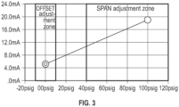
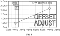
- FIGS. 2-8 show graphs depicting adjusting the offset of an exemplary measuring device 10 of the present disclosure.
- adjustment member 14 for adjusting the measuring device 10 readings at zero pressure (Offset adjustment).
- FIG. 2 depicts a graph showing the output of a measuring device 10 that is configured to be a 4mA to 20mA pressure transducer 10, with 4mA configured to be a zero kPa (psi) pressure reading, and 20mA configured to be the maximum range of the pressure transducer 10 and is configured to correspond to a 689.5 kPa (100 psi) pressure reading.
- the measuring device 10 can be operated at 137.9 kPa (20 psi).
- a user would first decrease the applied pressure on the measuring device 10 to within a first parameter range of the process (e.g., from about plus 10% pressure to about minus 10% pressure that is applied to measuring device 10), as shown in FIG. 3 (pressure is brought down to zero kPa (psi)).
- the power to the transducer 10 can be turned off, and then turned back on.
- a magnet member 14 can be tapped or contacted/placed/positioned (e.g., using the correct knock-on or tapping security code/rhythm/sequence) against or proximal to the housing 12 in a pre-determined or target area of the housing 12 to place the measuring device into an adjustment mode that enables the subsequent adjustment of offset (because the measuring device 10 is being operated within a first parameter range of the process) of measuring device 10 via subsequent contact or placement of magnet member 14 against or proximal to measuring device 10 (e.g., against or proximal to the target area of the housing 12).
- the adjustments to the output rolls over to a lower adjustment limit (e.g., lower adjustment limit of offset - as shown in FIG. 6 ), and then increments positive from the lower adjustment limit as shown in FIGS. 7 and 8 (e.g., by each subsequent tap/knock/placement of the magnet member 14 against or proximal to housing 12).
- a lower adjustment limit e.g., lower adjustment limit of offset - as shown in FIG. 6
- increments positive from the lower adjustment limit as shown in FIGS. 7 and 8 e.g., by each subsequent tap/knock/placement of the magnet member 14 against or proximal to housing 12.
- FIG. 8 depicts the output offset of measuring device 10 being re-calibrated to zero kPa (psi) at 4mA of measuring device 10 (e.g., within plus or minus 0.01% error).
- a user can remove the adjustment member from housing 14 and wait a pre-determined period of time (e.g., after about 30 seconds of last contact/placement of the magnet member 14 against or proximal to housing 12; after about 10 seconds of last contact/placement of the magnet member 14 against or proximal to housing 12; etc.).
- a pre-determined period of time e.g., after about 30 seconds of last contact/placement of the magnet member 14 against or proximal to housing 12; after about 10 seconds of last contact/placement of the magnet member 14 against or proximal to housing 12; etc.
- the measuring device 10 then responds (after waiting the pre-determined period of time) by sending a first signal (e.g., a high current) and then a second signal (e.g., a low current), and thereafter exits the adjustment mode (e.g., enters a non-adjustment mode). It is noted that measuring device 10 may just send one signal, or may send a plurality of signals to signify exiting the adjustment mode.
- a first signal e.g., a high current
- a second signal e.g., a low current
- the adjustment mode e.g., enters a non-adjustment mode. It is noted that measuring device 10 may just send one signal, or may send a plurality of signals to signify exiting the adjustment mode.
- any changes made to the offset or span (or both) of the output are stored permanently in non-volatile memory of measuring device 10, and the output annunciates this by briefly going high then low within a few seconds.
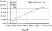
- FIGS. 9-12 show graphs depicting adjusting the span of an exemplary measuring device 10 of the present disclosure.
- adjustment member 14 for adjusting the measuring device 10 readings at a higher pressure by changing the output scale (Span adjustment).
- FIG. 9 depicts a graph showing the output of a measuring device 10 that is configured to be a 4mA to 20mA pressure transducer 10, with 4mA configured to be a zero kPa (psi) pressure reading, and 20mA configured to be the maximum range of the pressure transducer 10 and is configured to correspond to a 689.5 kPa (100 psi) pressure reading.
- the measuring device 10 can be operated at 137.9 kPa (20 psi).
- a user would first increase the applied pressure on the measuring device 10 to within a second parameter range of the process (e.g., e.g., at about 40% or greater pressure that is applied to measuring device 10; etc.), as shown in FIG. 10 (pressure is brought up to 551.6 kPa (80 psi)).
- the power to the transducer 10 can be turned off, and then turned back on.
- a user can remove the adjustment member from housing 14 and wait a pre-determined period of time (e.g., after about 30 seconds of last contact/placement of the magnet member 14 against or proximal to housing 12; after about 10 seconds of last contact/placement of the magnet member 14 against or proximal to housing 12; etc.).
- a pre-determined period of time e.g., after about 30 seconds of last contact/placement of the magnet member 14 against or proximal to housing 12; after about 10 seconds of last contact/placement of the magnet member 14 against or proximal to housing 12; etc.
- the measuring device 10 then responds (after waiting the pre-determined period of time) by sending a first signal (e.g., a high current) and then a second signal (e.g., a low current), and thereafter exits the adjustment mode. It is noted that measuring device 10 may just send one signal, or may send a plurality of signals to signify exiting the adjustment mode.
- a first signal e.g., a high current
- a second signal e.g., a low current
- measuring device 10 may just send one signal, or may send a plurality of signals to signify exiting the adjustment mode.
- adjustment features e.g., adjusting offset and/or span
- exemplary measuring device 10 via adjustment member 14 it also very advantageous in offering user or field calibration for any well-sealed measuring device 10, such as submersible transducers 10, hermetically sealed devices 10, or even all-welded construction devices 10 or the like.
- the timing and range of various parts or sections of these adjustment methods/processes are variable.
- the 30 second window or time-frame after power-up may be changed to 10 seconds, or any other suitable duration.
- the pressure ranges (or other input variable on similar devices 10) to distinguish between an Offset or Span adjustment can be varied or defined for custom applications.
- the knock code itself may be any suitable sequence or timing/duty cycle (or even the timing for detecting morse-code for example).
- the annunciation signal may be embodied by some other signal(s) or sequence(s).
- the magnet tap/placement may even be electromagnetic (allowing faster exercise, or more complex input sequencing/security coding, or remote adjustment).
- the output signal does not need to be analog - it may be digital.
- the magnetic input method for external input may not be limited to Offset & Span adjustment (and secure access).
- it may be used for manifold purposes - as a device reset, trigger input (for datalogging or a timer, for example).
- the exemplary measuring devices 10 with adjustment member 14 are able to adjust both zero and span.
- the knock code feature prevents accidental or unauthorized adjustment and allows the feature to be implemented in such a way as to comply with the IEC-61508 standard for functional safety.
- the annunciation feature (triggered when the knock code is accepted, and when calibration adjustment completes) allows a user to know with certainty that the calibration adjustment has been committed/completed/entered with respect to device 10.
Landscapes
- Physics & Mathematics (AREA)
- General Physics & Mathematics (AREA)
- Chemical & Material Sciences (AREA)
- Analytical Chemistry (AREA)
- Engineering & Computer Science (AREA)
- Technology Law (AREA)
- Measuring Fluid Pressure (AREA)
Claims (16)
- Verfahren zum Einstellen eines Messsystems umfassend:Durchführen eines Prozesses;Einbauen einer Messvorrichtung (10) in Bezug auf den Prozess zum Messen eines dem Prozess zugeordneten Parameters;Anlegen Strom an die Messvorrichtung (10);Positionieren eines Einstellelements (14) gegen oder in der Nähe eines Zielbereichs der Messvorrichtung (10) und innerhalb einer vorbestimmten Zeitspanne nach dem Anlegen von Energie an die Messvorrichtung (10), um die Messvorrichtung (10) in einen Einstellmodus zu versetzen, der eine nachfolgende Einstellung von einem oder mehreren Merkmalen der Messvorrichtung (10) über nachfolgendes Positionieren des Einstellelements (14) gegen oder in der Nähe des Zielbereichs ermöglicht;Positionieren dann des Einstellelements (14) gegen oder in der Nähe des Zielbereichs, während sich die Messvorrichtung in dem Einstellmodus befindet, um ein oder mehrere Merkmale der Messvorrichtung (10) einzustellen.
- Verfahren nach Anspruch 1, wobei der Prozess unter Druck durchgeführt wird; und
wobei die Messvorrichtung (10) eine abgedichtete Druckmessvorrichtung ist. - Verfahren nach Anspruch 1, wobei die Messvorrichtung (10) aus der Gruppe bestehend aus (i) einer Druckmessvorrichtung, (ii) einer Temperaturmessvorrichtung, (iii) einem Druckwandler, (iv) einem Druckgeber und (v) einer abgedichteten Signalformungsvorrichtung ausgewählt wird.
- Verfahren nach Anspruch 1, wobei das Einstellelement (14) ein Magnetelement ist.
- Verfahren nach Anspruch 1, wobei die Messvorrichtung (10) ein Erfassungselement enthält; und
wobei das Erfassungselement eine magnetisch empfindliche logische Eingabevorrichtung ist. - Verfahren nach Anspruch 1, wobei die Einstellung des einen oder der mehreren Merkmale der Messvorrichtung mindestens eines der folgenden Merkmale umfasst: (i) Einstellen eines digitalen oder analogen Ausgangs der Messvorrichtung und (ii) Einstellen eines Offsets oder einer Spanne der Messvorrichtung.
- Verfahren nach Anspruch 1, wobei die Einstellung des einen oder der mehreren Merkmale der Messvorrichtung erfolgt, ohne dass einen Aufnahmebehälter oder ein Gehäuse der Messvorrichtung gebrochen wird.
- Verfahren nach Anspruch 1, wobei das Positionieren des Einstellelements gegen oder in der Nähe des Zielbereichs einen vorbestimmten sequentiellen Code oder eine Versetzungsgeschwindigkeit des Einstellelements gegen oder in der Nähe des Zielbereichs erfordert, um die Messvorrichtung (10) in den Einstellmodus zu versetzen.
- Verfahren nach Anspruch 8, wobei der vorbestimmte sequenzielle Code oder die Versetzungsgeschwindigkeit zwei oder mehr Schläge oder Versetzungen des Einstellelements gegen oder in der Nähe des Zielbereichs umfasst, um die Messvorrichtung (10) in den Einstellmodus zu versetzen.
- Verfahren nach Anspruch 1, wobei die Messvorrichtung vor dem Eintritt in den Einstellmodus ein erstes und ein zweites Signal sendet.
- Verfahren nach Anspruch 1, wobei der Einstellmodus zwischen dem Betreiben oder dem Bedienen durch Einstellen eines ersten Merkmals der Messvorrichtung (10) und dem Betreiben oder dem Bedienen durch Einstellen eines zweiten Merkmals der Messvorrichtung in Abhängigkeit von dem Zahlen- oder Prozentwert des Parameters des Prozesses umschaltet, der auf die Messvorrichtung verwendet wird.
- Verfahren nach Anspruch 11, wobei das Verfahren unter Druck betrieben wird;wobei das Einstellen des ersten Merkmals das Einstellen eines Offsets der Messvorrichtung (10) umfasst; undwobei das Einstellen des zweiten Merkmals das Einstellen einer Spanne der Messvorrichtung (10) umfasst.
- Verfahren nach Anspruch 12, wobei der Einstellmodus zwischen dem Einstellen des ersten und des zweiten Merkmals in Abhängigkeit von dem auf die Messvorrichtung (10) verwendeten Druck umschaltet.
- Verfahren nach Anspruch 1, wobei jedes nachfolgende Positionieren des Einstellelements gegen oder in der Nähe des Zielbereichs, während sich die Messvorrichtung (10) in dem Einstellmodus befindet, ein oder mehrere Merkmale der Messvorrichtung inkremental einstellt.
- Verfahren nach Anspruch 14, wobei, nachdem eine Vielzahl positiver inkrementaler Einstellungen des einen oder der mehreren Merkmale eine obere Einstellgrenze erreicht hat, sendet das nächste nachfolgende Positionieren des Einstellelements gegen oder in der Nähe des Zielbereichs die nächste inkrementale Einstellung zu einer Untereinstellgrenze und dann die nächste nachfolgende Einstellung sich aus der Untereinstellgrenze positiv erhöht.
- Verfahren nach Anspruch 1, wobei:die Messvorrichtung (10) eine abgedichtete Signalformungsvorrichtung ist;die Messvorrichtung (10) mindestens ein erstes Signal sendet, bevor sie in den Einstellmodus übergeht;wenn die Messvorrichtung (10) in einem ersten Parameterbereich des Prozesses betrieben wird, kann ein erstes Merkmal der Messvorrichtung eingestellt werden, indem das Einstellelement (14) dann gegen oder in der Nähe des Zielbereichs positioniert wird;wenn die Messvorrichtung (10) in einem zweiten Parameterbereich des Prozesses betrieben wird, kann ein zweites Merkmal der Messvorrichtung eingestellt werden, indem das Einstellelement (14) dann gegen oder in der Nähe des Zielbereichs positioniert wird;jedes nachfolgende Positionieren des Einstellelements (14) gegen oder in der Nähe des Zielbereichs, während sich die Messvorrichtung (10) in dem Einstellmodus befindet, ein oder mehrere Merkmale der Messvorrichtung inkremental einstellt; undnachdem sich die Messvorrichtung (10) in dem Einstellmodus befindet und nach einer Zeitspanne von Untätigkeit des Positionierens des Einstellelements (14) gegen oder in der Nähe des Zielbereichs, tritt die Messvorrichtung (10) in einen Nicht-Einstellmodus ein.
Applications Claiming Priority (2)
| Application Number | Priority Date | Filing Date | Title |
|---|---|---|---|
| US16/422,165 US11280644B2 (en) | 2019-05-24 | 2019-05-24 | Adjustment member for measuring devices |
| PCT/US2020/033700 WO2020242846A1 (en) | 2019-05-24 | 2020-05-20 | Adjustment member for measuring devices |
Publications (3)
| Publication Number | Publication Date |
|---|---|
| EP3977060A1 EP3977060A1 (de) | 2022-04-06 |
| EP3977060A4 EP3977060A4 (de) | 2023-06-21 |
| EP3977060B1 true EP3977060B1 (de) | 2025-01-08 |
Family
ID=73456733
Family Applications (1)
| Application Number | Title | Priority Date | Filing Date |
|---|---|---|---|
| EP20814918.7A Active EP3977060B1 (de) | 2019-05-24 | 2020-05-20 | Einstellelement für messvorrichtungen |
Country Status (6)
| Country | Link |
|---|---|
| US (1) | US11280644B2 (de) |
| EP (1) | EP3977060B1 (de) |
| JP (1) | JP7261322B2 (de) |
| CN (1) | CN114207385B (de) |
| CA (1) | CA3141493C (de) |
| WO (1) | WO2020242846A1 (de) |
Family Cites Families (24)
| Publication number | Priority date | Publication date | Assignee | Title |
|---|---|---|---|---|
| GB887564A (en) * | 1957-11-21 | 1962-01-17 | Watton Engineering Co Ltd | Improvements in measuring and gauging devices |
| DE2758856C2 (de) * | 1977-12-30 | 1986-09-25 | Conducta Gesellschaft für Meß- und Regeltechnik mbH & Co, 7016 Gerlingen | Meßwertumformer, insbesondere für direkt messende Betriebsanalysengeräte |
| US4476706A (en) * | 1982-01-18 | 1984-10-16 | Delphian Partners | Remote calibration system |
| US4638656A (en) * | 1984-10-17 | 1987-01-27 | The Foxboro Company | Apparatus and method for calibrating span of pressure measuring instruments |
| JPH0230036U (de) * | 1988-04-07 | 1990-02-26 | ||
| US4926674A (en) * | 1988-11-03 | 1990-05-22 | Innovex Inc. | Self-zeroing pressure signal generator |
| US5332965A (en) * | 1992-06-22 | 1994-07-26 | Durakool Incorporated | Contactless linear angular position sensor having an adjustable flux concentrator for sensitivity adjustment and temperature compensation |
| JP3309583B2 (ja) * | 1994-09-02 | 2002-07-29 | 株式会社日立製作所 | プロセス状態検出器 |
| EP0795463A4 (de) * | 1995-10-17 | 2000-01-12 | Seiko Epson Corp | Messvorrichtung, zusatzantriebssystem mit solcher messvorrichtung und nullpunkteinstellvorrichtung für einen drehmomentsensor für das zusatzantriebssystem |
| JP2000065668A (ja) * | 1998-08-24 | 2000-03-03 | Toshiba Corp | 圧力及び差圧伝送器の自動校正装置 |
| DE10016636A1 (de) * | 2000-04-04 | 2001-10-18 | Siemens Ag | Stellungsregler, insbesondere für ein durch einen Antrieb betätigbares Ventil |
| JP3854500B2 (ja) * | 2001-12-07 | 2006-12-06 | 矢崎総業株式会社 | 炭酸ガス検知器の校正方法 |
| DE10207228A1 (de) | 2002-02-21 | 2003-09-04 | Bosch Gmbh Robert | Verfahren zur Kalibrierung eines Sensors und Schaltungsanordnung zum Betreiben eines Sensors |
| US6910381B2 (en) * | 2002-05-31 | 2005-06-28 | Mykrolis Corporation | System and method of operation of an embedded system for a digital capacitance diaphragm gauge |
| KR200312926Y1 (ko) * | 2003-01-16 | 2003-05-14 | 이유성 | 디지털 압력계 |
| DE102007034060B4 (de) * | 2007-07-20 | 2012-11-08 | Siemens Ag | Stelleinrichtung für ein Auf/Zu-Ventil |
| US7503222B1 (en) * | 2008-03-12 | 2009-03-17 | Ashcroft, Inc. | Span adjustment for suspended movement measuring devices |
| US8335659B2 (en) * | 2010-07-15 | 2012-12-18 | Tyco Electronics Corporation | Linear position sensor system |
| US8322365B2 (en) * | 2010-08-17 | 2012-12-04 | Codman & Shurtleff, Inc. | Implantable adjustable valve |
| EP2581766B1 (de) * | 2011-10-14 | 2023-11-29 | Omron Co., Ltd. | Fotoelektrischer Sensor |
| DE102013202090A1 (de) * | 2013-02-08 | 2014-08-14 | Wika Alexander Wiegand Se & Co. Kg | Druckmessgerät |
| JP2014178132A (ja) * | 2013-03-13 | 2014-09-25 | Nippon Dempa Kogyo Co Ltd | 外力検出装置 |
| PL2957872T3 (pl) * | 2014-06-18 | 2018-08-31 | Caterpillar Global Mining Europe Gmbh | Urządzenie wykrywające do cyfrowego czujnika położenia liniowego |
| CN105466466B (zh) * | 2016-01-04 | 2017-09-12 | 中国兵器工业集团第二一四研究所苏州研发中心 | 一种自动量程的mems电容式传感器 |
-
2019
- 2019-05-24 US US16/422,165 patent/US11280644B2/en active Active
-
2020
- 2020-05-20 CN CN202080051348.7A patent/CN114207385B/zh active Active
- 2020-05-20 CA CA3141493A patent/CA3141493C/en active Active
- 2020-05-20 EP EP20814918.7A patent/EP3977060B1/de active Active
- 2020-05-20 JP JP2021569349A patent/JP7261322B2/ja active Active
- 2020-05-20 WO PCT/US2020/033700 patent/WO2020242846A1/en not_active Ceased
Also Published As
| Publication number | Publication date |
|---|---|
| WO2020242846A1 (en) | 2020-12-03 |
| JP2022532803A (ja) | 2022-07-19 |
| US20200370930A1 (en) | 2020-11-26 |
| JP7261322B2 (ja) | 2023-04-19 |
| US11280644B2 (en) | 2022-03-22 |
| CA3141493A1 (en) | 2020-12-03 |
| CA3141493C (en) | 2024-03-26 |
| CN114207385B (zh) | 2024-03-29 |
| EP3977060A1 (de) | 2022-04-06 |
| EP3977060A4 (de) | 2023-06-21 |
| CN114207385A (zh) | 2022-03-18 |
| BR112021023361A2 (pt) | 2022-03-03 |
Similar Documents
| Publication | Publication Date | Title |
|---|---|---|
| EP1864088B1 (de) | Winkelpositionserfassung mittels mehrerer konfigurierter magnetischer drehsensoren | |
| EP3674668B1 (de) | Multiturn-absolutcodierer, codierungsverfahren und roboter | |
| US20040113813A1 (en) | Wireless transmitting pressure measurement device | |
| US7849750B2 (en) | Sensing apparatus of bourdon pressure gauge | |
| RU2008142769A (ru) | Устройство обеспечения безопасности для мониторинга целостности закрытых объектов | |
| US11169000B2 (en) | Multi-turn measurement system | |
| WO2008088421A2 (en) | Automated mechanical integrity verification | |
| Chesmond | Control system technology | |
| Bolton | Mechatronics: a multidisciplinary approach | |
| CA3141493C (en) | Adjustment member for measuring devices | |
| EP0471865A1 (de) | Volumetrischer Verdrängungsdurchflussmesser | |
| US6949924B2 (en) | Electromechanical rotation sensing device | |
| EP1845352A1 (de) | Verfahren zur drehwinkel- und drehmomenterfassung | |
| US20090212767A1 (en) | Remote transmitter for analogue gauges | |
| EP3351946A1 (de) | Zangenmessgerät | |
| BR112021023361B1 (pt) | Método para ajustar um sistema de medição e método para ajustar um sistema de medição de pressão | |
| WO2016150644A1 (en) | A drive unit for controlling a control valve element, a method for operating a drive unit of a control valve element and a control valve unit | |
| KR100676715B1 (ko) | 전자식 부르동튜브 압력계 | |
| JP2016027457A (ja) | 電子機器 | |
| EP2489204B1 (de) | Hörsystem mit analogem Bedienungselement | |
| Nyce | Understanding Position Sensors | |
| CN219935177U (zh) | 新型暗装式微差压变送器 | |
| CN118809263B (zh) | 一种基于电磁感应的自供电智能刀柄 | |
| RU2174236C1 (ru) | Способ допускового контроля магнитоэлектрического измерителя тока и устройство для его осуществления | |
| KR200319697Y1 (ko) | 점화상태 감시 시스템 |
Legal Events
| Date | Code | Title | Description |
|---|---|---|---|
| STAA | Information on the status of an ep patent application or granted ep patent |
Free format text: STATUS: THE INTERNATIONAL PUBLICATION HAS BEEN MADE |
|
| PUAI | Public reference made under article 153(3) epc to a published international application that has entered the european phase |
Free format text: ORIGINAL CODE: 0009012 |
|
| STAA | Information on the status of an ep patent application or granted ep patent |
Free format text: STATUS: REQUEST FOR EXAMINATION WAS MADE |
|
| 17P | Request for examination filed |
Effective date: 20211222 |
|
| AK | Designated contracting states |
Kind code of ref document: A1 Designated state(s): AL AT BE BG CH CY CZ DE DK EE ES FI FR GB GR HR HU IE IS IT LI LT LU LV MC MK MT NL NO PL PT RO RS SE SI SK SM TR |
|
| DAV | Request for validation of the european patent (deleted) | ||
| DAX | Request for extension of the european patent (deleted) | ||
| REG | Reference to a national code |
Ref country code: DE Ref legal event code: R079 Free format text: PREVIOUS MAIN CLASS: G01D0018000000 Ipc: G01D0003020000 Ref country code: DE Ref legal event code: R079 Ref document number: 602020044586 Country of ref document: DE Free format text: PREVIOUS MAIN CLASS: G01D0018000000 Ipc: G01D0003020000 |
|
| A4 | Supplementary search report drawn up and despatched |
Effective date: 20230524 |
|
| RIC1 | Information provided on ipc code assigned before grant |
Ipc: G01D 3/02 20060101AFI20230517BHEP |
|
| P01 | Opt-out of the competence of the unified patent court (upc) registered |
Effective date: 20230524 |
|
| GRAP | Despatch of communication of intention to grant a patent |
Free format text: ORIGINAL CODE: EPIDOSNIGR1 |
|
| STAA | Information on the status of an ep patent application or granted ep patent |
Free format text: STATUS: GRANT OF PATENT IS INTENDED |
|
| RIC1 | Information provided on ipc code assigned before grant |
Ipc: G01D 3/02 20060101AFI20240712BHEP |
|
| INTG | Intention to grant announced |
Effective date: 20240806 |
|
| GRAS | Grant fee paid |
Free format text: ORIGINAL CODE: EPIDOSNIGR3 |
|
| GRAA | (expected) grant |
Free format text: ORIGINAL CODE: 0009210 |
|
| STAA | Information on the status of an ep patent application or granted ep patent |
Free format text: STATUS: THE PATENT HAS BEEN GRANTED |
|
| AK | Designated contracting states |
Kind code of ref document: B1 Designated state(s): AL AT BE BG CH CY CZ DE DK EE ES FI FR GB GR HR HU IE IS IT LI LT LU LV MC MK MT NL NO PL PT RO RS SE SI SK SM TR |
|
| REG | Reference to a national code |
Ref country code: GB Ref legal event code: FG4D |
|
| REG | Reference to a national code |
Ref country code: CH Ref legal event code: EP |
|
| REG | Reference to a national code |
Ref country code: DE Ref legal event code: R096 Ref document number: 602020044586 Country of ref document: DE |
|
| REG | Reference to a national code |
Ref country code: IE Ref legal event code: FG4D |
|
| REG | Reference to a national code |
Ref country code: LT Ref legal event code: MG9D |
|
| REG | Reference to a national code |
Ref country code: NL Ref legal event code: MP Effective date: 20250108 |
|
| REG | Reference to a national code |
Ref country code: AT Ref legal event code: MK05 Ref document number: 1758588 Country of ref document: AT Kind code of ref document: T Effective date: 20250108 |
|
| PG25 | Lapsed in a contracting state [announced via postgrant information from national office to epo] |
Ref country code: NL Free format text: LAPSE BECAUSE OF FAILURE TO SUBMIT A TRANSLATION OF THE DESCRIPTION OR TO PAY THE FEE WITHIN THE PRESCRIBED TIME-LIMIT Effective date: 20250108 |
|
| PG25 | Lapsed in a contracting state [announced via postgrant information from national office to epo] |
Ref country code: RS Free format text: LAPSE BECAUSE OF FAILURE TO SUBMIT A TRANSLATION OF THE DESCRIPTION OR TO PAY THE FEE WITHIN THE PRESCRIBED TIME-LIMIT Effective date: 20250408 |
|
| PG25 | Lapsed in a contracting state [announced via postgrant information from national office to epo] |
Ref country code: FI Free format text: LAPSE BECAUSE OF FAILURE TO SUBMIT A TRANSLATION OF THE DESCRIPTION OR TO PAY THE FEE WITHIN THE PRESCRIBED TIME-LIMIT Effective date: 20250108 |
|
| PG25 | Lapsed in a contracting state [announced via postgrant information from national office to epo] |
Ref country code: PL Free format text: LAPSE BECAUSE OF FAILURE TO SUBMIT A TRANSLATION OF THE DESCRIPTION OR TO PAY THE FEE WITHIN THE PRESCRIBED TIME-LIMIT Effective date: 20250108 |
|
| PGFP | Annual fee paid to national office [announced via postgrant information from national office to epo] |
Ref country code: DE Payment date: 20250529 Year of fee payment: 6 |
|
| PG25 | Lapsed in a contracting state [announced via postgrant information from national office to epo] |
Ref country code: ES Free format text: LAPSE BECAUSE OF FAILURE TO SUBMIT A TRANSLATION OF THE DESCRIPTION OR TO PAY THE FEE WITHIN THE PRESCRIBED TIME-LIMIT Effective date: 20250108 |
|
| PGFP | Annual fee paid to national office [announced via postgrant information from national office to epo] |
Ref country code: GB Payment date: 20250527 Year of fee payment: 6 |
|
| PG25 | Lapsed in a contracting state [announced via postgrant information from national office to epo] |
Ref country code: IS Free format text: LAPSE BECAUSE OF FAILURE TO SUBMIT A TRANSLATION OF THE DESCRIPTION OR TO PAY THE FEE WITHIN THE PRESCRIBED TIME-LIMIT Effective date: 20250508 Ref country code: NO Free format text: LAPSE BECAUSE OF FAILURE TO SUBMIT A TRANSLATION OF THE DESCRIPTION OR TO PAY THE FEE WITHIN THE PRESCRIBED TIME-LIMIT Effective date: 20250408 |
|
| PG25 | Lapsed in a contracting state [announced via postgrant information from national office to epo] |
Ref country code: HR Free format text: LAPSE BECAUSE OF FAILURE TO SUBMIT A TRANSLATION OF THE DESCRIPTION OR TO PAY THE FEE WITHIN THE PRESCRIBED TIME-LIMIT Effective date: 20250108 |
|
| PG25 | Lapsed in a contracting state [announced via postgrant information from national office to epo] |
Ref country code: PT Free format text: LAPSE BECAUSE OF FAILURE TO SUBMIT A TRANSLATION OF THE DESCRIPTION OR TO PAY THE FEE WITHIN THE PRESCRIBED TIME-LIMIT Effective date: 20250508 Ref country code: LV Free format text: LAPSE BECAUSE OF FAILURE TO SUBMIT A TRANSLATION OF THE DESCRIPTION OR TO PAY THE FEE WITHIN THE PRESCRIBED TIME-LIMIT Effective date: 20250108 |
|
| PGFP | Annual fee paid to national office [announced via postgrant information from national office to epo] |
Ref country code: FR Payment date: 20250526 Year of fee payment: 6 |
|
| PG25 | Lapsed in a contracting state [announced via postgrant information from national office to epo] |
Ref country code: GR Free format text: LAPSE BECAUSE OF FAILURE TO SUBMIT A TRANSLATION OF THE DESCRIPTION OR TO PAY THE FEE WITHIN THE PRESCRIBED TIME-LIMIT Effective date: 20250409 Ref country code: BG Free format text: LAPSE BECAUSE OF FAILURE TO SUBMIT A TRANSLATION OF THE DESCRIPTION OR TO PAY THE FEE WITHIN THE PRESCRIBED TIME-LIMIT Effective date: 20250108 |
|
| PG25 | Lapsed in a contracting state [announced via postgrant information from national office to epo] |
Ref country code: AT Free format text: LAPSE BECAUSE OF FAILURE TO SUBMIT A TRANSLATION OF THE DESCRIPTION OR TO PAY THE FEE WITHIN THE PRESCRIBED TIME-LIMIT Effective date: 20250108 |
|
| PG25 | Lapsed in a contracting state [announced via postgrant information from national office to epo] |
Ref country code: SE Free format text: LAPSE BECAUSE OF FAILURE TO SUBMIT A TRANSLATION OF THE DESCRIPTION OR TO PAY THE FEE WITHIN THE PRESCRIBED TIME-LIMIT Effective date: 20250108 |
|
| PG25 | Lapsed in a contracting state [announced via postgrant information from national office to epo] |
Ref country code: SM Free format text: LAPSE BECAUSE OF FAILURE TO SUBMIT A TRANSLATION OF THE DESCRIPTION OR TO PAY THE FEE WITHIN THE PRESCRIBED TIME-LIMIT Effective date: 20250108 |
|
| REG | Reference to a national code |
Ref country code: DE Ref legal event code: R097 Ref document number: 602020044586 Country of ref document: DE |
|
| PG25 | Lapsed in a contracting state [announced via postgrant information from national office to epo] |
Ref country code: DK Free format text: LAPSE BECAUSE OF FAILURE TO SUBMIT A TRANSLATION OF THE DESCRIPTION OR TO PAY THE FEE WITHIN THE PRESCRIBED TIME-LIMIT Effective date: 20250108 |
|
| PG25 | Lapsed in a contracting state [announced via postgrant information from national office to epo] |
Ref country code: CZ Free format text: LAPSE BECAUSE OF FAILURE TO SUBMIT A TRANSLATION OF THE DESCRIPTION OR TO PAY THE FEE WITHIN THE PRESCRIBED TIME-LIMIT Effective date: 20250108 Ref country code: EE Free format text: LAPSE BECAUSE OF FAILURE TO SUBMIT A TRANSLATION OF THE DESCRIPTION OR TO PAY THE FEE WITHIN THE PRESCRIBED TIME-LIMIT Effective date: 20250108 |
|
| PG25 | Lapsed in a contracting state [announced via postgrant information from national office to epo] |
Ref country code: RO Free format text: LAPSE BECAUSE OF FAILURE TO SUBMIT A TRANSLATION OF THE DESCRIPTION OR TO PAY THE FEE WITHIN THE PRESCRIBED TIME-LIMIT Effective date: 20250108 |
|
| PG25 | Lapsed in a contracting state [announced via postgrant information from national office to epo] |
Ref country code: SK Free format text: LAPSE BECAUSE OF FAILURE TO SUBMIT A TRANSLATION OF THE DESCRIPTION OR TO PAY THE FEE WITHIN THE PRESCRIBED TIME-LIMIT Effective date: 20250108 |
|
| PLBE | No opposition filed within time limit |
Free format text: ORIGINAL CODE: 0009261 |
|
| STAA | Information on the status of an ep patent application or granted ep patent |
Free format text: STATUS: NO OPPOSITION FILED WITHIN TIME LIMIT |
|
| REG | Reference to a national code |
Ref country code: CH Ref legal event code: L10 Free format text: ST27 STATUS EVENT CODE: U-0-0-L10-L00 (AS PROVIDED BY THE NATIONAL OFFICE) Effective date: 20251119 |
|
| 26N | No opposition filed |
Effective date: 20251009 |
|
| REG | Reference to a national code |
Ref country code: CH Ref legal event code: H13 Free format text: ST27 STATUS EVENT CODE: U-0-0-H10-H13 (AS PROVIDED BY THE NATIONAL OFFICE) Effective date: 20251223 |
|
| PG25 | Lapsed in a contracting state [announced via postgrant information from national office to epo] |
Ref country code: LU Free format text: LAPSE BECAUSE OF NON-PAYMENT OF DUE FEES Effective date: 20250520 |
|
| PG25 | Lapsed in a contracting state [announced via postgrant information from national office to epo] |
Ref country code: CH Free format text: LAPSE BECAUSE OF NON-PAYMENT OF DUE FEES Effective date: 20250531 |
|
| PG25 | Lapsed in a contracting state [announced via postgrant information from national office to epo] |
Ref country code: IT Free format text: LAPSE BECAUSE OF FAILURE TO SUBMIT A TRANSLATION OF THE DESCRIPTION OR TO PAY THE FEE WITHIN THE PRESCRIBED TIME-LIMIT Effective date: 20250108 |
|
| REG | Reference to a national code |
Ref country code: BE Ref legal event code: MM Effective date: 20250531 |
|
| PG25 | Lapsed in a contracting state [announced via postgrant information from national office to epo] |
Ref country code: MC Free format text: LAPSE BECAUSE OF FAILURE TO SUBMIT A TRANSLATION OF THE DESCRIPTION OR TO PAY THE FEE WITHIN THE PRESCRIBED TIME-LIMIT Effective date: 20250108 |
|
| PG25 | Lapsed in a contracting state [announced via postgrant information from national office to epo] |
Ref country code: IE Free format text: LAPSE BECAUSE OF NON-PAYMENT OF DUE FEES Effective date: 20250520 |
|
| PG25 | Lapsed in a contracting state [announced via postgrant information from national office to epo] |
Ref country code: BE Free format text: LAPSE BECAUSE OF NON-PAYMENT OF DUE FEES Effective date: 20250531 |