EP3976408B1 - Module de refroidissement pour véhicule automobile électrique à turbomachine tangentielle - Google Patents
Module de refroidissement pour véhicule automobile électrique à turbomachine tangentielle Download PDFInfo
- Publication number
- EP3976408B1 EP3976408B1 EP20729960.3A EP20729960A EP3976408B1 EP 3976408 B1 EP3976408 B1 EP 3976408B1 EP 20729960 A EP20729960 A EP 20729960A EP 3976408 B1 EP3976408 B1 EP 3976408B1
- Authority
- EP
- European Patent Office
- Prior art keywords
- turbomachine
- cooling module
- axis
- rotation
- cooling
- Prior art date
- Legal status (The legal status is an assumption and is not a legal conclusion. Google has not performed a legal analysis and makes no representation as to the accuracy of the status listed.)
- Active
Links
Images



Classifications
-
- B—PERFORMING OPERATIONS; TRANSPORTING
- B60—VEHICLES IN GENERAL
- B60K—ARRANGEMENT OR MOUNTING OF PROPULSION UNITS OR OF TRANSMISSIONS IN VEHICLES; ARRANGEMENT OR MOUNTING OF PLURAL DIVERSE PRIME-MOVERS IN VEHICLES; AUXILIARY DRIVES FOR VEHICLES; INSTRUMENTATION OR DASHBOARDS FOR VEHICLES; ARRANGEMENTS IN CONNECTION WITH COOLING, AIR INTAKE, GAS EXHAUST OR FUEL SUPPLY OF PROPULSION UNITS IN VEHICLES
- B60K11/00—Arrangement in connection with cooling of propulsion units
- B60K11/08—Air inlets for cooling; Shutters or blinds therefor
-
- B—PERFORMING OPERATIONS; TRANSPORTING
- B60—VEHICLES IN GENERAL
- B60K—ARRANGEMENT OR MOUNTING OF PROPULSION UNITS OR OF TRANSMISSIONS IN VEHICLES; ARRANGEMENT OR MOUNTING OF PLURAL DIVERSE PRIME-MOVERS IN VEHICLES; AUXILIARY DRIVES FOR VEHICLES; INSTRUMENTATION OR DASHBOARDS FOR VEHICLES; ARRANGEMENTS IN CONNECTION WITH COOLING, AIR INTAKE, GAS EXHAUST OR FUEL SUPPLY OF PROPULSION UNITS IN VEHICLES
- B60K11/00—Arrangement in connection with cooling of propulsion units
- B60K11/06—Arrangement in connection with cooling of propulsion units with air cooling
-
- B—PERFORMING OPERATIONS; TRANSPORTING
- B60—VEHICLES IN GENERAL
- B60K—ARRANGEMENT OR MOUNTING OF PROPULSION UNITS OR OF TRANSMISSIONS IN VEHICLES; ARRANGEMENT OR MOUNTING OF PLURAL DIVERSE PRIME-MOVERS IN VEHICLES; AUXILIARY DRIVES FOR VEHICLES; INSTRUMENTATION OR DASHBOARDS FOR VEHICLES; ARRANGEMENTS IN CONNECTION WITH COOLING, AIR INTAKE, GAS EXHAUST OR FUEL SUPPLY OF PROPULSION UNITS IN VEHICLES
- B60K11/00—Arrangement in connection with cooling of propulsion units
- B60K11/08—Air inlets for cooling; Shutters or blinds therefor
- B60K11/085—Air inlets for cooling; Shutters or blinds therefor with adjustable shutters or blinds
-
- F—MECHANICAL ENGINEERING; LIGHTING; HEATING; WEAPONS; BLASTING
- F01—MACHINES OR ENGINES IN GENERAL; ENGINE PLANTS IN GENERAL; STEAM ENGINES
- F01P—COOLING OF MACHINES OR ENGINES IN GENERAL; COOLING OF INTERNAL-COMBUSTION ENGINES
- F01P11/00—Component parts, details, or accessories not provided for in, or of interest apart from, groups F01P1/00 - F01P9/00
- F01P11/10—Guiding or ducting cooling-air, to, or from, liquid-to-air heat exchangers
-
- F—MECHANICAL ENGINEERING; LIGHTING; HEATING; WEAPONS; BLASTING
- F01—MACHINES OR ENGINES IN GENERAL; ENGINE PLANTS IN GENERAL; STEAM ENGINES
- F01P—COOLING OF MACHINES OR ENGINES IN GENERAL; COOLING OF INTERNAL-COMBUSTION ENGINES
- F01P5/00—Pumping cooling-air or liquid coolants
- F01P5/02—Pumping cooling-air; Arrangements of cooling-air pumps, e.g. fans or blowers
- F01P5/06—Guiding or ducting air to, or from, ducted fans
Definitions
- the invention relates to the automotive field, and more particularly to the field of air circulation for cooling the engine and its equipment.
- a motor vehicle heat exchanger generally comprises tubes, in which a heat transfer fluid is intended to circulate, in particular a liquid such as water, and heat exchange elements connected to these tubes, often referred to as "fins" or “spacers".
- the fins increase the exchange surface area between the tubes and the ambient air.
- a ventilation device in order to further increase the heat exchange between the heat transfer fluid and the ambient air, it is common for a ventilation device to be used in addition, to generate or increase an air flow directed towards the tubes and fins.
- the airflow generated by the blades of such a fan is turbulent, in particular due to the circular geometry of the propeller, and generally only reaches part of the surface of the heat exchanger (circular area of the exchanger facing the fan propeller).
- the heat exchange therefore does not take place homogeneously over the entire surface of the tubes and fins.
- the blades when the fan is not required to be switched on (typically when the heat exchange with non-accelerated ambient air is sufficient to cool the heat transfer fluid circulating in the exchanger), the blades partially obstruct the flow of ambient air towards the tubes and fins, which hinders the air circulation towards the exchanger and thus limits the heat exchange with the heat transfer fluid.
- Such a fan is also relatively bulky, particularly due to the dimensions of the propeller required to achieve effective engine cooling, which makes its integration into a motor vehicle time-consuming and difficult.
- a cooling module for a motor vehicle is known from the document US 4,519,343 A .
- the aim of the invention is to at least partially remedy these drawbacks.
- the heat exchanger(s) has/have dimensions suitable for being cooled only by means of one or more lower cooling bays.
- the tangential turbomachines make it possible to create an air flow through all the heat exchangers with a much better efficiency than if a propeller fan were implemented.
- the arrangement of the two turbomachines makes it possible to reduce or even avoid any impact between two air jets leaving the turbomachines, which ensures good aeraulic and acoustic performance for the cooling module.
- the axis of rotation of the first tangential turbomachine and the axis of rotation of the second tangential turbomachine are mounted parallel to each other.
- the axis of rotation of the first turbomachine is disposed facing an end edge of the working surface and the axis of rotation of the second turbomachine is disposed facing the inside of the working surface.
- the working surface is delimited by a first direction, called length, and a second direction, called height, orthogonal to the length, the axis of rotation of the second turbomachine being arranged in an area between one fifth and four fifths of said height.
- the axis of rotation of the second turbomachine is arranged in an area between one third and two thirds of said height.
- the invention also relates to a motor vehicle with an electric motor, comprising a body, a bumper and a as described previously, the body defining at least one cooling bay arranged under the bumper, the cooling module being arranged opposite the at least one cooling bay.
- each turbomachine operates by suction, that is to say that it sucks in the ambient air to bring it into contact with the various heat exchangers, as will be detailed.
- each turbomachine operates by blowing, blowing the air towards the various heat exchangers.
- FIG. 1 schematically illustrates the front part of a motor vehicle 10 with an electric motor 12.
- the vehicle 10 comprises in particular a body 14 and a bumper 16 carried by a chassis (not shown) of the motor vehicle 10.
- the body 14 defines a cooling bay 18, that is to say an opening through the body 14.
- the cooling bay 18 is here unique.
- This cooling bay 18 is located in the lower part of the front face 14a of the body 14. In the example illustrated, the cooling bay 18 is located under the bumper 16.
- a grid 20 can be arranged in the cooling bay 18 to prevent projectiles from passing through the cooling bay 18.
- a cooling module 22 is arranged opposite the cooling bay 18. The grid 20 makes it possible in particular to protect this cooling module 22.
- the cooling module 22 comprises a ventilation device 24 associated with at least one heat exchanger.
- the ventilation device 1 comprises at least one tangential fan, also called a tangential turbomachine hereinafter, which draws in an air flow F to the heat exchanger or heat exchangers.
- the cooling module comprises two turbomachines 28-1, 28-2, detailed hereinafter.
- the cooling module 22 essentially comprises a housing or fairing 24 forming an internal air channel.
- the fairing 24 makes it possible to house at least one tangential turbomachine.
- a rear portion of the fairing forms in particular here the volute of a tangential turbomachine 28.
- the turbomachines 28-1, 28-2 make it possible to cool one or more heat exchangers 30 1 -30 3 .
- Each tangential turbomachine comprises a rotor or turbine 32-1, 32-2 (or tangential propeller).
- the turbine has a substantially cylindrical shape.
- the turbine advantageously comprises several stages of blades (or vanes).
- the turbine is rotatably mounted around an axis of rotation A 32-1 , A 32-2 .
- the cooling module 22 comprises a first turbomachine 28-1 and a second turbomachine 28-2, conforming to the turbomachine 28 described previously.
- all the heat exchangers delimit a surface S, called the working surface, a section of which is substantially rectangular in a plane (Y, Z).
- the Y direction corresponds to a horizontal direction while the Z direction corresponds to a vertical direction, when the module is installed in the motor vehicle.
- the surface S is delimited by two opposite end edges 38, 39 extending in the direction Y, called length, and by two other opposite end edges 40, 41, in the direction Z.
- the surface S corresponds to the rectangle defined by the exchanger 30, or if several exchangers are present, by the largest heat exchanger.
- the height of the surface S is the sum of the heights of the vertically juxtaposed (superimposed) exchangers
- the length of the surface S is the sum of the lengths of the horizontally juxtaposed exchangers.
- the first and second turbomachines 28-1 and 28-2 are mounted parallel to each other, that is to say that the axis of rotation A 32-1 of the turbine 32-1 of the first turbomachine 28-1 extends parallel to the axis of rotation A 32-2 of the turbine 32-2 of the second turbomachine 28-2.
- the rotation axes A 32-1 , A 32-2 are parallel to the Y direction, i.e. mounted horizontally.
- the invention is not limited to this configuration and the rotation axes A 32-1 , A 32-2 can be mounted vertically, i.e. parallel to the Z axis.
- the volute of the first turbomachine 28-1 comprises a portion 44-1 for guiding air around the turbomachine 32-1 to an air outlet from the module, referenced 46-1.
- the air guide portion 44-1 advantageously comprises a wall in the form of a truncated spiral.
- volute of the second turbomachine 28-2 comprises a portion 44-2 for guiding air around the turbomachine 32-2 to an air outlet from the module, referenced 46-2.
- the guide portion 44-2 advantageously comprises a wall in the form of a truncated spiral.
- the two outputs 46-1, 46-2 are arranged opposite each other.
- the air outlet 46-1 of the first turbomachine 28-1 is arranged opposite the guide portion 44-2 of the second turbomachine 28-2, which significantly reduces the acoustic waves generated by the cooling module, compared to the configuration where the two outlets face each other of the Figure 2 .
- This configuration ensures that the air distribution of an air flow F1 from the first turbomachine 28-1 via the associated outlet 46-1 is substantially the same and in particular in the same direction as the distribution of an air flow F2 from the second turbomachine 28-2 via the associated outlet 46-2.
- an axis parallel to the Z direction and passing through the middle of the lengths of the set of heat exchangers is an axis of symmetry of the set of two turbomachines 28-1, 28-2.
- the portion 44-1, 44-2 of the volute fairing 24 2 is arranged above the respective outlet 46-1, 46-2, and the air flows F1 and F2 are substantially vertical and downward.
- the axis of rotation A 32-1 of the first turbomachine 28-1 is arranged facing the end edge 40 of the surface S and the axis rotation A 32-2 of the second turbomachine 28-2 is arranged opposite the interior of the surface S.
- the rotation axis A 32-2 of the second turbomachine 28-2 is arranged in the middle of the height of the surface S.
- the rotation axis A 32-2 of the second turbomachine 28-2 is arranged in the upper third of the height of the surface S.
- the invention is not limited to these geometries, and, depending on the configuration of the heat exchangers and/or the cooling power required for each exchanger, it is possible to position the turbomachines so as to dedicate them to respective exchangers.
- the module 22 is provided with air guide means 50-1, 50-2 associated with each turbomachine 28-1, 28-2.
- the open position is particularly advantageous when the vehicle is traveling at high speed, in which case it is possible to shut down the turbomachines 28-1, 28-2.
Landscapes
- Engineering & Computer Science (AREA)
- Chemical & Material Sciences (AREA)
- Combustion & Propulsion (AREA)
- Mechanical Engineering (AREA)
- Transportation (AREA)
- General Engineering & Computer Science (AREA)
- Cooling, Air Intake And Gas Exhaust, And Fuel Tank Arrangements In Propulsion Units (AREA)
- Motor Or Generator Cooling System (AREA)
- Structures Of Non-Positive Displacement Pumps (AREA)
Description
- L'invention se rapporte au domaine de l'automobile, et plus particulièrement au domaine de la circulation d'air pour le refroidissement du moteur et de ses équipements.
- Les véhicules à moteur, qu'ils soient à combustion ou électriques, ont besoin d'évacuer les calories que génère leur fonctionnement et sont pour cela équipés d'échangeurs de chaleur. Un échangeur de chaleur de véhicule automobile comprend généralement des tubes, dans lesquels un fluide caloporteur est destiné à circuler, notamment un liquide tel que l'eau, et des éléments d'échange de chaleur reliés à ces tubes, souvent désignés par le terme « ailettes » ou « intercalaires ». Les ailettes permettent d'augmenter la surface d'échange entre les tubes et l'air ambiant.
- Toutefois, afin d'augmenter encore l'échange de chaleur entre le fluide caloporteur et l'air ambiant, il est fréquent qu'un dispositif de ventilation soit utilisé en sus, pour générer ou accroitre un flux d'air dirigé vers les tubes et les ailettes.
- De façon connue, un tel dispositif de ventilation comprend un ventilateur à hélice.
- Le flux d'air généré par les pales d'un tel ventilateur est turbulent, notamment en raison de la géométrie circulaire de l'hélice, et n'atteint en général qu'une partie seulement de la surface de l'échangeur de chaleur (zone circulaire de l'échangeur faisant face à l'hélice du ventilateur). L'échange de chaleur ne se fait donc pas de façon homogène sur toute la surface des tubes et des ailettes.
- En outre, lorsque la mise en marche du ventilateur ne s'avère pas nécessaire (typiquement lorsque l'échange de chaleur avec de l'air ambiant non accéléré suffit à refroidir le fluide caloporteur circulant dans l'échangeur), les pales obstruent en partie l'écoulement de l'air ambiant vers les tubes et les ailettes, ce qui gêne la circulation d'air vers l'échangeur et limite ainsi l'échange de chaleur avec le fluide caloporteur.
- Un tel ventilateur est en outre relativement encombrant, à cause notamment des dimensions nécessaires de l'hélice pour obtenir un refroidissement moteur effectif, ce qui rend long et délicat son intégration dans un véhicule automobile.
- Cette intégration est d'autant plus compliquée dans un véhicule électrique, dont la face avant laisse peu de place pour y loger les éléments de refroidissement du véhicule.
- Un module de refroidissement pour véhicule automobile est connu du document
US 4 519 343 A . - Le but de l'invention est de remédier au moins partiellement à ces inconvénients.
- A cet effet, l'invention a pour objet un module de refroidissement pour véhicule automobile selon la revendication 1.
- Ainsi, avantageusement, le ou les échangeurs thermiques présente/nt des dimensions adaptées pour n'être refroidi/s qu'au moyen d'une ou plusieurs baies de refroidissement inférieures. En outre, les turbomachines tangentielles permettent de créer un flux d'air à travers tous les échangeurs thermiques avec un bien meilleur rendement que si un ventilateur à hélice était mis en œuvre.
- De surcroît, l'agencement des deux turbomachines permet de réduire voire d'éviter tout impact entre deux jets d'air sortant des turbomachines, ce qui assure au module de refroidissement une bonne performance aéraulique et acoustique .
- Selon un autre aspect, l'axe de rotation de la première turbomachine tangentielle et l'axe de rotation de la deuxième turbomachine tangentielle sont montés parallèlement l'un à l'autre.
- Selon un autre aspect, l'axe de rotation de la première turbomachine est disposé face à un bord d'extrémité de la surface de travail et l'axe de rotation de la deuxième turbomachine est disposé face à l'intérieur de la surface de travail.
- Selon un autre aspect, la surface de travail est délimitée par une première direction, dite longueur, et une deuxième direction, dite hauteur, orthogonale à la longueur, l'axe de rotation de la deuxième turbomachine étant disposé dans une zone comprise entre un cinquième et quatre cinquième de ladite hauteur.
- Selon un autre aspect, l'axe de rotation de la deuxième turbomachine est disposé dans une zone comprise entre un tiers et deux tiers de ladite hauteur.
- L'invention a également pour objet un véhicule automobile à moteur électrique, comprenant une carrosserie, un pare-chocs et un tel que décrit précédemment, la carrosserie définissant au moins une baie de refroidissement disposée sous le pare-chocs, le module de refroidissement étant disposé en regard de la au moins une baie de refroidissement.
- D'autres caractéristiques, détails et avantages de l'invention apparaîtront encore à la lecture de la description qui va suivre. Celle-ci est purement illustrative et doit être lue en regard des dessins annexés sur lesquels :
-
Fig. 1
[Fig. 1 ] représente schématiquement la partie avant d'un véhicule automobile à moteur électrique, vu de côté. -
Fig. 2
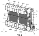
[Fig. 2 ] est une vue en perspective d'un module de refroidissement qui ne fait pas partie de l'invention, des volets de guidage étant omis. -
Fig. 3
[Fig. 3 ] est une vue en perspective d'un module de refroidissement selon un autre mode de réalisation, des volets de guidage étant omis. -
Fig. 4
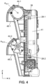
[Fig. 4 ] est une vue de côté du module de lafigure 3 . -
Fig. 5
[Fig. 5 ] est une vue en perspective du module de lafigure 3 , des volets de guidage étant illustrés. -
Fig. 6
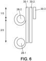
[Fig. 6 ] est une vue schématique de côté d'une variante de réalisation du module de lafigure 3 . - Dans la suite de la description, les éléments identiques ou de fonction identique portent le même signe de référence. À fin de concision de la présente description, ces éléments ne sont pas décrits en détails dans chaque mode de réalisation. Au contraire, seules les différences entre les variantes de réalisation sont décrites en détails.
- On note que, dans les exemples illustrés, qui sont préférés, chaque turbomachine fonctionne en aspiration, c'est-à-dire qu'elle aspire l'air ambiant pour le conduire au contact des différents échangeurs thermiques, comme il va être détaillés. Alternativement, cependant, chaque turbomachine fonctionne par soufflage, soufflant l'air vers les différents échangeurs thermiques.
- La
figure 1 illustre de manière schématique la partie avant d'un véhicule automobile 10 à moteur électrique 12. Le véhicule 10 comporte notamment une carrosserie 14 et un pare-chocs 16 portés par un châssis (non représenté) du véhicule automobile 10. La carrosserie 14 définit une baie de refroidissement 18, c'est-à-dire une ouverture à travers la carrosserie 14. La baie de refroidissement 18 est ici unique. Cette baie de refroidissement 18 se trouve en partie basse de la face avant 14a de la carrosserie 14. Dans l'exemple illustré, la baie de refroidissement 18 est située sous le pare-chocs 16. Une grille 20 peut être disposée dans la baie de refroidissement 18 pour éviter que des projectiles puissent traverser la baie de refroidissement 18. Un module de refroidissement 22 est disposé en vis-à-vis de la baie de refroidissement 18. La grille 20 permet notamment de protéger ce module de refroidissement 22. - Le module de refroidissement 22 comprend un dispositif de ventilation 24 associé à au moins un échangeur thermique.
- Comme il ressort des figures, le dispositif de ventilation 1 comprend au moins un ventilateur tangentiel, aussi nommé turbomachine tangentielle ci-après, qui aspire un flux d'air F à destination de l'échangeur de chaleur ou des échangeurs de chaleur. Sur les modes de réalisation illustrés, le module de refroidissement comprend deux turbomachines 28-1, 28-2, détaillées ci-après.
- Tel qu'illustré, le module de refroidissement 22 comporte essentiellement un boîtier ou carénage 24 formant un canal interne d'air. Le carénage 24 permet de loger au moins une turbomachine tangentielle. Une partie arrière du carénage forme notamment ici la volute d'une turbomachine tangentielle 28.
- Comme il ressort des figures, les turbomachines 28-1, 28-2 permettent de refroidir un ou plusieurs échangeurs de chaleurs 301-303.
- Chaque turbomachine tangentielle comprend un rotor ou turbine 32-1, 32-2 (ou hélice tangentielle). La turbine a une forme sensiblement cylindrique. La turbine comporte avantageusement plusieurs étages de pales (ou aubes). La turbine est montée rotative autour d'un axe de rotation A32-1, A32-2.
- Les modes de réalisation des sont maintenant décrits.
- Comme il ressort de ces figures, le module de refroidissement 22 comprend une première turbomachine 28-1 et une deuxième turbomachine 28-2, conformes à la turbomachine 28 décrite précédemment.
- Sur les
figures 2 à 6 , l'ensemble des échangeurs thermiques délimitent une surface S, appelée surface de travail, dont une section est sensiblement rectangulaire dans un plan (Y, Z). - De préférence, la direction Y correspond à une direction horizontale tandis que la direction Z correspond à une direction verticale, quand le module est installé dans le véhicule automobile.
- La surface S est délimitée par deux bords d'extrémité opposés 38, 39 s'étendant selon la direction Y, dite longueur, et par deux autres bords d'extrémité opposés 40, 41, selon la direction Z.
- Sur la
figure 5 , la surface S correspond au rectangle défini par l'échangeur 30, ou si plusieurs échangeurs sont présents, par le plus grand échangeur thermique. Néanmoins, il est également possible de juxtaposer plusieurs échangeurs verticalement et/ou horizontalement, auquel cas la hauteur de la surface S est la somme des hauteurs des échangeurs juxtaposés verticalement (superposés), et la longueur de la surface S est la somme des longueurs des échangeurs juxtaposés horizontalement. - Les première et deuxième turbomachines 28-1 et 28-2 sont montées parallèlement l'une à l'autre, c'est-à-dire que l'axe de rotation A32-1 de la turbine 32-1 de la première turbomachine 28-1 s'étend parallèlement à l'axe de rotation A32-2 de la turbine 32-2 de la deuxième turbomachine 28-2.
- Sur les
figures 2 à 6 , les axes de rotation A32-1, A32-2 sont parallèles à la direction Y, c'est-à-dire montés horizontalement. Néanmoins, bien entendu, l'invention n'est pas limitée à cette configuration et les axes de rotation A32-1, A32-2 peuvent être montés verticalement, c'est-à-dire parallèlement à l'axe Z. - Comme également visible sur les
figures 2 à 6 , la volute de la première turbomachine 28-1 comprend une portion de guidage 44-1 d'air autour de la turbomachine 32-1 jusqu'à une sortie de l'air hors du module, référencée 46-1. De manière connue, la portion de guidage d'air 44-1 comprend avantageusement une paroi en forme de spirale tronquée. - De manière analogue, la volute de la deuxième turbomachine 28-2 comprend une portion de guidage 44-2 d'air autour de la turbomachine 32-2 jusqu'à une sortie de l'air hors du module, référencée 46-2. La portion de guidage 44-2 comprend avantageusement une paroi en forme de spirale tronquée.
- Selon le mode de réalisation de la
figure 2 , qui ne fait pas partie de l'invention, les deux sorties 46-1, 46-2 sont disposées en regard l'une de l'autre. - Selon le mode de réalisation des
figures 3 à 6 , la sortie d'air 46-1 de la première turbomachine 28-1 est disposée en regard de la portion de guidage 44-2 de la deuxième turbomachine 28-2, ce qui réduit nettement les ondes acoustiques générées par le module de refroidissement, par rapport à la configuration où les deux sorties se font face de lafigure 2 . - Cette configuration assure que la répartition d'air d'un flux d'air F1 issu de la première turbomachine 28-1 via la sortie associée 46-1 est sensiblement la même et en particulier dans le même sens que la répartition d'un flux d'air F2 issu de la deuxième turbomachine 28-2 via la sortie associée 46-2.
- On note qu'un axe parallèle à la direction Z et passant par le milieu des longueurs de l'ensemble des échangeurs thermiques est un axe de symétrie de l'ensemble des deux turbomachines 28-1, 28-2.
- Comme visible sur les
figures 3 à 5 , la partie 44-1, 44-2 du carénage de volute 242 est disposée au-dessus de la sortie respective 46-1, 46-2, et les flux d'air F1 et F2 sont sensiblement verticaux et vers le bas. - Ainsi, quand le véhicule se trouve dans un environnement humide voire mouillé, comme en cas de pluie ou de passage à gué, la turbomachine 28-1, 28-2 est protégée, puisque l'eau ne peut pas être stockée dans la volute mais au contraire est évacuée par la sortie 46-1, 46-2. De ce fait, toute submersion du module de refroidissement est évitée.
- Comme il ressort également des figures, l'axe de rotation A32-1 de la première turbomachine 28-1 est disposé face au bord d'extrémité 40 de la surface S et l'axe de rotation A32-2 de la deuxième turbomachine 28-2 est disposé en regard de l'intérieur de la surface S.
- Sur les
figures 3 et4 , l'axe de rotation A32-2 de la deuxième turbomachine 28-2 est disposé au milieu de la hauteur de la surface S. - Sur la
figure 6 , l'axe de rotation A32-2 de la deuxième turbomachine 28-2 est disposé au tiers supérieur de la hauteur de la surface S. - Néanmoins, l'invention n'est pas limitée à ces géométries, et, selon la configuration des échangeurs thermiques et/ou la puissance de refroidissement requise pour chaque échangeur, il est possible de positionner les turbomachines de sorte à les dédier à des échangeurs respectifs.
- Avantageusement, l'axe de rotation A32-2 de la deuxième turbomachine 28-2 est disposé dans une zone comprise entre un cinquième et quatre cinquième de ladite hauteur, de préférence entre un tiers et deux tiers de ladite hauteur.
- Comme illustré sur la
figure 5 , le module 22 est muni de moyen de guidage d'air 50-1, 50-2 associé à chaque turbomachine 28-1, 28-2. - Chaque moyen de guidage d'air 50-1, 50-2 comprend un ensemble de volets 52 montés pivotants entre une position de fermeture du module de refroidissement (comme visible sur la
figure 4 ) et au moins une position d'ouverture du module de refroidissement (non illustrée). - La position d'ouverture est particulièrement avantageuse quand le véhicule roule à grande vitesse, auquel cas il est possible de mettre les turbomachines 28-1, 28-2 à l'arrêt.
- Le nombre de volets 52 associés à la première turbomachine 28-1 peut être identique ou au contraire différent du nombre de volets 52 associés à la deuxième turbomachine 28-2, selon la position respective des turbomachines notamment.
Claims (6)
- Module de refroidissement (22) pour véhicule automobile (10), comprenant :- au moins un échangeur thermique (301-303) délimitant une surface, dite surface de travail,- au moins une première turbomachine tangentielle (28-1) et une deuxième turbomachine tangentielle (28-2), chacune desdites turbomachines (28-1, 28-2) étant apte à créer un flux d'air au contact de ladite surface de travail,chacune desdites turbomachines comprenant un rotor en rotation autour d'un axe et une volute de logement du rotor, comportant une portion de guidage d'air (44-1, 44-2) et une sortie d'air (46-1, 46-2) hors de la turbomachine. lesdites turbomachines (28-1, 28-2) étant agencées de sorte que la sortie d'air de la première turbomachine (28-1) est disposée en regard de la portion de guidage de la deuxième turbomachine (28-2),caractérisé en ce quele module de refroidissement (22) comprend des volets de guidage d'air (52) montés pivotants entre une position de fermeture du module de refroidissement (22) et au moins une position d'ouverture du module de refroidissement (22), la portion de guidage d'air (44-1, 44-2) d'une turbomachine étant disposée au-dessus de sa sortie d'air (46-1, 46-2) respective, de façon à ce que les flux d'air (F1, F2) sont sensiblement verticaux et vers le bas.
- Module de refroidissement selon la revendication précédente, dans lequel l'axe de rotation (A32-1) de la première turbomachine tangentielle (28-1) et l'axe de rotation (A32-2) de la deuxième turbomachine tangentielle (28-2) sont montés parallèlement l'un à l'autre.
- Module de refroidissement selon l'une des revendications précédentes, dans lequel l'axe de rotation (A32-1) de la première turbomachine (28-1) est disposé face à un bord d'extrémité (40) de la surface de travail (S) et l'axe de rotation (A32-2) de la deuxième turbomachine (28-2) est disposé face à l'intérieur de la surface de travail (S).
- Module de refroidissement selon la revendication précédente, dans lequel la surface de travail (S) est délimitée par une première direction, dite longueur (Y), et une deuxième direction, dite hauteur (Z), orthogonale à la longueur, l'axe de rotation (A32-2) de la deuxième turbomachine (28-2) étant disposé dans une zone comprise entre un cinquième et quatre cinquième de ladite hauteur.
- Module de refroidissement selon la revendication précédente, dans lequel l'axe de rotation (A32-2) de la deuxième turbomachine (28-2) est disposé dans une zone comprise entre un tiers et deux tiers de ladite hauteur.
- Véhicule automobile, comprenant une carrosserie (14), un pare-chocs (16) et un module de refroidissement (22) selon l'une quelconque des revendications précédentes, la carrosserie (14) définissant au moins une baie de refroidissement (18) disposée sous le pare-chocs, le module de refroidissement (22) étant disposé en regard de la au moins une baie de refroidissement (18).
Applications Claiming Priority (2)
| Application Number | Priority Date | Filing Date | Title |
|---|---|---|---|
| FR1905466A FR3096308A1 (fr) | 2019-05-24 | 2019-05-24 | Module de refroidissement pour véhicule automobile électrique à turbomachine tangentielle |
| PCT/EP2020/063763 WO2020239485A1 (fr) | 2019-05-24 | 2020-05-18 | Module de refroidissement pour véhicule automobile électrique à turbomachine tangentielle |
Publications (2)
| Publication Number | Publication Date |
|---|---|
| EP3976408A1 EP3976408A1 (fr) | 2022-04-06 |
| EP3976408B1 true EP3976408B1 (fr) | 2025-05-14 |
Family
ID=68072664
Family Applications (1)
| Application Number | Title | Priority Date | Filing Date |
|---|---|---|---|
| EP20729960.3A Active EP3976408B1 (fr) | 2019-05-24 | 2020-05-18 | Module de refroidissement pour véhicule automobile électrique à turbomachine tangentielle |
Country Status (5)
| Country | Link |
|---|---|
| US (1) | US11780321B2 (fr) |
| EP (1) | EP3976408B1 (fr) |
| CN (1) | CN114126908A (fr) |
| FR (1) | FR3096308A1 (fr) |
| WO (1) | WO2020239485A1 (fr) |
Families Citing this family (1)
| Publication number | Priority date | Publication date | Assignee | Title |
|---|---|---|---|---|
| FR3105367A1 (fr) * | 2019-12-20 | 2021-06-25 | Valeo Systemes Thermiques | Module de dispositif de ventilation pour module de refroidissement de véhicule automobile, dispositif de ventilation comportant un tel module et module de refroidissement pour véhicule automobile comprenant un tel dispositif de ventilation |
Family Cites Families (16)
| Publication number | Priority date | Publication date | Assignee | Title |
|---|---|---|---|---|
| US4519343A (en) * | 1982-11-08 | 1985-05-28 | Aisin Seiki Kabushiki Kaisha | Engine cooling system |
| JPS6189926A (ja) * | 1984-10-11 | 1986-05-08 | Toyota Motor Corp | 空冷式インタ−ク−ラ構造 |
| JP3937624B2 (ja) * | 1998-03-13 | 2007-06-27 | 株式会社デンソー | 車両用冷却装置 |
| US6401801B1 (en) * | 1999-12-10 | 2002-06-11 | Caterpillar Inc. | Twin fan cooling system |
| US7231894B2 (en) * | 2002-01-17 | 2007-06-19 | E.A. Technical Services Limited | Rotary positive displacement machine |
| JP2006298175A (ja) * | 2005-04-21 | 2006-11-02 | Nissan Motor Co Ltd | 車両用冷却装置 |
| WO2008055216A2 (fr) * | 2006-10-31 | 2008-05-08 | Enviro-Cool, Inc. | Système de gestion de l'air pour camions poids lourds avec régulation thermique sous le capot |
| US7703282B1 (en) * | 2007-12-10 | 2010-04-27 | Iea, Inc. | Heat exchanger with horizontal flowing charge air cooler |
| US20130063071A1 (en) * | 2011-09-09 | 2013-03-14 | Donnell Lee Walters | Forced Air Turbine Electric Automobile (FATE) |
| FR2981887B1 (fr) * | 2011-11-02 | 2015-04-17 | Renault Sas | Guide d'air structurel et modulaire a fonction de face avant technique de moteur de vehicule automobile et vehicule ainsi equipe. |
| KR101500383B1 (ko) * | 2013-10-14 | 2015-03-09 | 현대자동차 주식회사 | 자동차의 에어 덕트 및 냉각 장치 |
| JP6180281B2 (ja) * | 2013-11-01 | 2017-08-16 | 株式会社ケーヒン・サーマル・テクノロジー | 蓄熱機能付き熱交換器およびその製造方法 |
| CN106524296A (zh) * | 2015-09-11 | 2017-03-22 | 珠海格力电器股份有限公司 | 分体落地式空调器 |
| FR3062879A1 (fr) * | 2017-02-16 | 2018-08-17 | Valeo Systemes Thermiques | Module de refroidissement par circulation d'air |
| DE102017007768A1 (de) * | 2017-08-16 | 2018-01-25 | Daimler Ag | Kühlvorrichtung für ein Kraftfahrzeug, insbesondere einen Kraftwagen |
| FR3085891B1 (fr) * | 2018-09-17 | 2022-09-02 | Valeo Systemes Thermiques | Module d’echange thermique pour vehicule automobile |
-
2019
- 2019-05-24 FR FR1905466A patent/FR3096308A1/fr not_active Ceased
-
2020
- 2020-05-18 CN CN202080050596.XA patent/CN114126908A/zh active Pending
- 2020-05-18 US US17/613,288 patent/US11780321B2/en active Active
- 2020-05-18 EP EP20729960.3A patent/EP3976408B1/fr active Active
- 2020-05-18 WO PCT/EP2020/063763 patent/WO2020239485A1/fr not_active Ceased
Also Published As
| Publication number | Publication date |
|---|---|
| US11780321B2 (en) | 2023-10-10 |
| FR3096308A1 (fr) | 2020-11-27 |
| US20220227221A1 (en) | 2022-07-21 |
| EP3976408A1 (fr) | 2022-04-06 |
| WO2020239485A1 (fr) | 2020-12-03 |
| CN114126908A (zh) | 2022-03-01 |
Similar Documents
| Publication | Publication Date | Title |
|---|---|---|
| FR3100584A1 (fr) | Dispositif de ventilation pour module de refroidissement de véhicule automobile | |
| FR3093760A1 (fr) | Module de refroidissement pour véhicule automobile électrique à turbomachine tangentielle | |
| WO2020188191A1 (fr) | Module de refroidissement pour véhicule automobile électrique à turbomachine tangentielle | |
| EP3976408B1 (fr) | Module de refroidissement pour véhicule automobile électrique à turbomachine tangentielle | |
| FR3115732A1 (fr) | Module de refroidissement pour véhicule automobile électrique ou hybride à turbomachine tangentielle avec échangeur thermique supplémentaire | |
| EP4077012A1 (fr) | Module de dispositif de ventilation pour module de refroidissement de véhicule automobile, dispositif de ventilation comportant un tel module et module de refroidissement pour véhicule automobile comprenant un tel dispositif de ventilation | |
| WO2021048494A1 (fr) | Procédé de fabrication d'un dispositif de ventilation pour module de refroidissement de véhicule automobile à turbomachine tangentielle | |
| WO2020239486A1 (fr) | Module de refroidissement pour véhicule automobile électrique à turbomachine tangentielle | |
| FR3093763A1 (fr) | Module de refroidissement à zone sacrificielle pour véhicule automobile électrique | |
| EP4204669B1 (fr) | Module de refroidissement pour véhicule automobile électrique à turbomachine tangentielle | |
| FR3105371A1 (fr) | Module de refroidissement pour véhicule automobile à turbomachine tangentielle | |
| EP3938632B1 (fr) | Module de refroidissement pour véhicule automobile électrique à turbomachine tangentielle | |
| WO2022106147A1 (fr) | Module de refroidissement pour véhicule automobile électrique ou hybride à turbomachine tangentielle avec échangeur de chaleur supplémentaire | |
| FR3100488A1 (fr) | Module de refroidissement pour véhicule automobile à deux turbomachines tangentielles et au moins un échangeur thermique | |
| EP4028654B1 (fr) | Module de refroidissement pour véhicule automobile à turbomachine tangentielle | |
| FR3141100A1 (fr) | Module de refroidissement pour véhicule automobile électrique ou hybride | |
| FR3093757A1 (fr) | Module de refroidissement pour véhicule automobile électrique à turbomachine tangentielle | |
| FR3115735A1 (fr) | Module de refroidissement pour véhicule automobile électrique ou hybride à turbomachine tangentielle | |
| EP3938232A1 (fr) | Module de refroidissement pour véhicule automobile | |
| FR3105373A1 (fr) | Module de refroidissement pour véhicule automobile à turbomachine tangentielle | |
| FR3100484A1 (fr) | Module de refroidissement pour véhicule automobile à turbomachine tangentielle | |
| FR3105110A1 (fr) | Module de refroidissement pour véhicule automobile à turbomachine tangentielle | |
| WO2021123556A1 (fr) | Dispositif de ventilation pour module de refroidissement de véhicule automobile | |
| WO2021123552A1 (fr) | Dispositif de ventilation pour module de refroidissement de véhicule automobile et module de refroidissement pour véhicule automobile comprenant un tel dispositif de ventilation | |
| FR3093762A1 (fr) | Module de refroidissement pour véhicule automobile électrique à turbomachine tangentielle |
Legal Events
| Date | Code | Title | Description |
|---|---|---|---|
| STAA | Information on the status of an ep patent application or granted ep patent |
Free format text: STATUS: UNKNOWN |
|
| STAA | Information on the status of an ep patent application or granted ep patent |
Free format text: STATUS: THE INTERNATIONAL PUBLICATION HAS BEEN MADE |
|
| PUAI | Public reference made under article 153(3) epc to a published international application that has entered the european phase |
Free format text: ORIGINAL CODE: 0009012 |
|
| STAA | Information on the status of an ep patent application or granted ep patent |
Free format text: STATUS: REQUEST FOR EXAMINATION WAS MADE |
|
| 17P | Request for examination filed |
Effective date: 20211125 |
|
| AK | Designated contracting states |
Kind code of ref document: A1 Designated state(s): AL AT BE BG CH CY CZ DE DK EE ES FI FR GB GR HR HU IE IS IT LI LT LU LV MC MK MT NL NO PL PT RO RS SE SI SK SM TR |
|
| DAV | Request for validation of the european patent (deleted) | ||
| DAX | Request for extension of the european patent (deleted) | ||
| P01 | Opt-out of the competence of the unified patent court (upc) registered |
Effective date: 20230528 |
|
| STAA | Information on the status of an ep patent application or granted ep patent |
Free format text: STATUS: EXAMINATION IS IN PROGRESS |
|
| 17Q | First examination report despatched |
Effective date: 20240510 |
|
| GRAP | Despatch of communication of intention to grant a patent |
Free format text: ORIGINAL CODE: EPIDOSNIGR1 |
|
| STAA | Information on the status of an ep patent application or granted ep patent |
Free format text: STATUS: GRANT OF PATENT IS INTENDED |
|
| INTG | Intention to grant announced |
Effective date: 20241217 |
|
| GRAS | Grant fee paid |
Free format text: ORIGINAL CODE: EPIDOSNIGR3 |
|
| GRAA | (expected) grant |
Free format text: ORIGINAL CODE: 0009210 |
|
| STAA | Information on the status of an ep patent application or granted ep patent |
Free format text: STATUS: THE PATENT HAS BEEN GRANTED |
|
| AK | Designated contracting states |
Kind code of ref document: B1 Designated state(s): AL AT BE BG CH CY CZ DE DK EE ES FI FR GB GR HR HU IE IS IT LI LT LU LV MC MK MT NL NO PL PT RO RS SE SI SK SM TR |
|
| REG | Reference to a national code |
Ref country code: GB Ref legal event code: FG4D Free format text: NOT ENGLISH |
|
| REG | Reference to a national code |
Ref country code: CH Ref legal event code: EP |
|
| REG | Reference to a national code |
Ref country code: DE Ref legal event code: R096 Ref document number: 602020051248 Country of ref document: DE |
|
| REG | Reference to a national code |
Ref country code: IE Ref legal event code: FG4D Free format text: LANGUAGE OF EP DOCUMENT: FRENCH |
|
| PGFP | Annual fee paid to national office [announced via postgrant information from national office to epo] |
Ref country code: DE Payment date: 20250617 Year of fee payment: 6 |
|
| PGFP | Annual fee paid to national office [announced via postgrant information from national office to epo] |
Ref country code: FR Payment date: 20250530 Year of fee payment: 6 |
|
| REG | Reference to a national code |
Ref country code: NL Ref legal event code: MP Effective date: 20250514 |
|
| PG25 | Lapsed in a contracting state [announced via postgrant information from national office to epo] |
Ref country code: PT Free format text: LAPSE BECAUSE OF FAILURE TO SUBMIT A TRANSLATION OF THE DESCRIPTION OR TO PAY THE FEE WITHIN THE PRESCRIBED TIME-LIMIT Effective date: 20250915 Ref country code: ES Free format text: LAPSE BECAUSE OF FAILURE TO SUBMIT A TRANSLATION OF THE DESCRIPTION OR TO PAY THE FEE WITHIN THE PRESCRIBED TIME-LIMIT Effective date: 20250514 Ref country code: FI Free format text: LAPSE BECAUSE OF FAILURE TO SUBMIT A TRANSLATION OF THE DESCRIPTION OR TO PAY THE FEE WITHIN THE PRESCRIBED TIME-LIMIT Effective date: 20250514 |
|
| REG | Reference to a national code |
Ref country code: LT Ref legal event code: MG9D |
|
| PG25 | Lapsed in a contracting state [announced via postgrant information from national office to epo] |
Ref country code: GR Free format text: LAPSE BECAUSE OF FAILURE TO SUBMIT A TRANSLATION OF THE DESCRIPTION OR TO PAY THE FEE WITHIN THE PRESCRIBED TIME-LIMIT Effective date: 20250815 Ref country code: NO Free format text: LAPSE BECAUSE OF FAILURE TO SUBMIT A TRANSLATION OF THE DESCRIPTION OR TO PAY THE FEE WITHIN THE PRESCRIBED TIME-LIMIT Effective date: 20250814 |
|
| PG25 | Lapsed in a contracting state [announced via postgrant information from national office to epo] |
Ref country code: NL Free format text: LAPSE BECAUSE OF FAILURE TO SUBMIT A TRANSLATION OF THE DESCRIPTION OR TO PAY THE FEE WITHIN THE PRESCRIBED TIME-LIMIT Effective date: 20250514 Ref country code: PL Free format text: LAPSE BECAUSE OF FAILURE TO SUBMIT A TRANSLATION OF THE DESCRIPTION OR TO PAY THE FEE WITHIN THE PRESCRIBED TIME-LIMIT Effective date: 20250514 |
|
| REG | Reference to a national code |
Ref country code: AT Ref legal event code: MK05 Ref document number: 1794518 Country of ref document: AT Kind code of ref document: T Effective date: 20250514 |
|
| PG25 | Lapsed in a contracting state [announced via postgrant information from national office to epo] |
Ref country code: BG Free format text: LAPSE BECAUSE OF FAILURE TO SUBMIT A TRANSLATION OF THE DESCRIPTION OR TO PAY THE FEE WITHIN THE PRESCRIBED TIME-LIMIT Effective date: 20250514 |
|
| PG25 | Lapsed in a contracting state [announced via postgrant information from national office to epo] |
Ref country code: HR Free format text: LAPSE BECAUSE OF FAILURE TO SUBMIT A TRANSLATION OF THE DESCRIPTION OR TO PAY THE FEE WITHIN THE PRESCRIBED TIME-LIMIT Effective date: 20250514 |
|
| PG25 | Lapsed in a contracting state [announced via postgrant information from national office to epo] |
Ref country code: AT Free format text: LAPSE BECAUSE OF FAILURE TO SUBMIT A TRANSLATION OF THE DESCRIPTION OR TO PAY THE FEE WITHIN THE PRESCRIBED TIME-LIMIT Effective date: 20250514 |
|
| PG25 | Lapsed in a contracting state [announced via postgrant information from national office to epo] |
Ref country code: RS Free format text: LAPSE BECAUSE OF FAILURE TO SUBMIT A TRANSLATION OF THE DESCRIPTION OR TO PAY THE FEE WITHIN THE PRESCRIBED TIME-LIMIT Effective date: 20250814 |
|
| PG25 | Lapsed in a contracting state [announced via postgrant information from national office to epo] |
Ref country code: IS Free format text: LAPSE BECAUSE OF FAILURE TO SUBMIT A TRANSLATION OF THE DESCRIPTION OR TO PAY THE FEE WITHIN THE PRESCRIBED TIME-LIMIT Effective date: 20250914 |
|
| PG25 | Lapsed in a contracting state [announced via postgrant information from national office to epo] |
Ref country code: LV Free format text: LAPSE BECAUSE OF FAILURE TO SUBMIT A TRANSLATION OF THE DESCRIPTION OR TO PAY THE FEE WITHIN THE PRESCRIBED TIME-LIMIT Effective date: 20250514 |
|
| REG | Reference to a national code |
Ref country code: CH Ref legal event code: H13 Free format text: ST27 STATUS EVENT CODE: U-0-0-H10-H13 (AS PROVIDED BY THE NATIONAL OFFICE) Effective date: 20251223 |
|
| PG25 | Lapsed in a contracting state [announced via postgrant information from national office to epo] |
Ref country code: DK Free format text: LAPSE BECAUSE OF FAILURE TO SUBMIT A TRANSLATION OF THE DESCRIPTION OR TO PAY THE FEE WITHIN THE PRESCRIBED TIME-LIMIT Effective date: 20250514 Ref country code: SM Free format text: LAPSE BECAUSE OF FAILURE TO SUBMIT A TRANSLATION OF THE DESCRIPTION OR TO PAY THE FEE WITHIN THE PRESCRIBED TIME-LIMIT Effective date: 20250514 |
|
| PG25 | Lapsed in a contracting state [announced via postgrant information from national office to epo] |
Ref country code: LU Free format text: LAPSE BECAUSE OF NON-PAYMENT OF DUE FEES Effective date: 20250518 |
|
| PG25 | Lapsed in a contracting state [announced via postgrant information from national office to epo] |
Ref country code: CH Free format text: LAPSE BECAUSE OF NON-PAYMENT OF DUE FEES Effective date: 20250531 |
|
| PG25 | Lapsed in a contracting state [announced via postgrant information from national office to epo] |
Ref country code: CZ Free format text: LAPSE BECAUSE OF FAILURE TO SUBMIT A TRANSLATION OF THE DESCRIPTION OR TO PAY THE FEE WITHIN THE PRESCRIBED TIME-LIMIT Effective date: 20250514 |
|
| PG25 | Lapsed in a contracting state [announced via postgrant information from national office to epo] |
Ref country code: EE Free format text: LAPSE BECAUSE OF FAILURE TO SUBMIT A TRANSLATION OF THE DESCRIPTION OR TO PAY THE FEE WITHIN THE PRESCRIBED TIME-LIMIT Effective date: 20250514 |
|
| PG25 | Lapsed in a contracting state [announced via postgrant information from national office to epo] |
Ref country code: SK Free format text: LAPSE BECAUSE OF FAILURE TO SUBMIT A TRANSLATION OF THE DESCRIPTION OR TO PAY THE FEE WITHIN THE PRESCRIBED TIME-LIMIT Effective date: 20250514 Ref country code: RO Free format text: LAPSE BECAUSE OF FAILURE TO SUBMIT A TRANSLATION OF THE DESCRIPTION OR TO PAY THE FEE WITHIN THE PRESCRIBED TIME-LIMIT Effective date: 20250514 |
|
| PG25 | Lapsed in a contracting state [announced via postgrant information from national office to epo] |
Ref country code: IT Free format text: LAPSE BECAUSE OF FAILURE TO SUBMIT A TRANSLATION OF THE DESCRIPTION OR TO PAY THE FEE WITHIN THE PRESCRIBED TIME-LIMIT Effective date: 20250514 |
|
| REG | Reference to a national code |
Ref country code: BE Ref legal event code: MM Effective date: 20250531 |
|
| REG | Reference to a national code |
Ref country code: DE Ref legal event code: R097 Ref document number: 602020051248 Country of ref document: DE |
|
| REG | Reference to a national code |
Ref country code: CH Ref legal event code: W10 Free format text: ST27 STATUS EVENT CODE: U-0-0-W10-W00 (AS PROVIDED BY THE NATIONAL OFFICE) Effective date: 20260218 |
|
| PG25 | Lapsed in a contracting state [announced via postgrant information from national office to epo] |
Ref country code: MC Free format text: LAPSE BECAUSE OF FAILURE TO SUBMIT A TRANSLATION OF THE DESCRIPTION OR TO PAY THE FEE WITHIN THE PRESCRIBED TIME-LIMIT Effective date: 20250514 |
|
| RAP2 | Party data changed (patent owner data changed or rights of a patent transferred) |
Owner name: VALEO ELECTRIFICATION |
|
| PLBE | No opposition filed within time limit |
Free format text: ORIGINAL CODE: 0009261 |
|
| STAA | Information on the status of an ep patent application or granted ep patent |
Free format text: STATUS: NO OPPOSITION FILED WITHIN TIME LIMIT |
|
| REG | Reference to a national code |
Ref country code: CH Ref legal event code: L10 Free format text: ST27 STATUS EVENT CODE: U-0-0-L10-L00 (AS PROVIDED BY THE NATIONAL OFFICE) Effective date: 20260325 |
|
| PG25 | Lapsed in a contracting state [announced via postgrant information from national office to epo] |
Ref country code: IE Free format text: LAPSE BECAUSE OF NON-PAYMENT OF DUE FEES Effective date: 20250518 |
|
| PG25 | Lapsed in a contracting state [announced via postgrant information from national office to epo] |
Ref country code: BE Free format text: LAPSE BECAUSE OF NON-PAYMENT OF DUE FEES Effective date: 20250531 |
|
| 26N | No opposition filed |
Effective date: 20260217 |